JP2015169089A - 圧縮機 - Google Patents
圧縮機 Download PDFInfo
- Publication number
- JP2015169089A JP2015169089A JP2014042902A JP2014042902A JP2015169089A JP 2015169089 A JP2015169089 A JP 2015169089A JP 2014042902 A JP2014042902 A JP 2014042902A JP 2014042902 A JP2014042902 A JP 2014042902A JP 2015169089 A JP2015169089 A JP 2015169089A
- Authority
- JP
- Japan
- Prior art keywords
- bolt
- discharge
- discharge valve
- compression mechanism
- compressor
- Prior art date
- Legal status (The legal status is an assumption and is not a legal conclusion. Google has not performed a legal analysis and makes no representation as to the accuracy of the status listed.)
- Pending
Links
Images





Classifications
-
- F—MECHANICAL ENGINEERING; LIGHTING; HEATING; WEAPONS; BLASTING
- F04—POSITIVE - DISPLACEMENT MACHINES FOR LIQUIDS; PUMPS FOR LIQUIDS OR ELASTIC FLUIDS
- F04B—POSITIVE-DISPLACEMENT MACHINES FOR LIQUIDS; PUMPS
- F04B39/00—Component parts, details, or accessories, of pumps or pumping systems specially adapted for elastic fluids, not otherwise provided for in, or of interest apart from, groups F04B25/00 - F04B37/00
- F04B39/0027—Pulsation and noise damping means
- F04B39/0033—Pulsation and noise damping means with encapsulations
- F04B39/0038—Pulsation and noise damping means with encapsulations of inlet or outlet channels
-
- F—MECHANICAL ENGINEERING; LIGHTING; HEATING; WEAPONS; BLASTING
- F04—POSITIVE - DISPLACEMENT MACHINES FOR LIQUIDS; PUMPS FOR LIQUIDS OR ELASTIC FLUIDS
- F04B—POSITIVE-DISPLACEMENT MACHINES FOR LIQUIDS; PUMPS
- F04B39/00—Component parts, details, or accessories, of pumps or pumping systems specially adapted for elastic fluids, not otherwise provided for in, or of interest apart from, groups F04B25/00 - F04B37/00
- F04B39/10—Adaptations or arrangements of distribution members
-
- F—MECHANICAL ENGINEERING; LIGHTING; HEATING; WEAPONS; BLASTING
- F04—POSITIVE - DISPLACEMENT MACHINES FOR LIQUIDS; PUMPS FOR LIQUIDS OR ELASTIC FLUIDS
- F04C—ROTARY-PISTON, OR OSCILLATING-PISTON, POSITIVE-DISPLACEMENT MACHINES FOR LIQUIDS; ROTARY-PISTON, OR OSCILLATING-PISTON, POSITIVE-DISPLACEMENT PUMPS
- F04C18/00—Rotary-piston pumps specially adapted for elastic fluids
- F04C18/30—Rotary-piston pumps specially adapted for elastic fluids having the characteristics covered by two or more of groups F04C18/02, F04C18/08, F04C18/22, F04C18/24, F04C18/48, or having the characteristics covered by one of these groups together with some other type of movement between co-operating members
- F04C18/34—Rotary-piston pumps specially adapted for elastic fluids having the characteristics covered by two or more of groups F04C18/02, F04C18/08, F04C18/22, F04C18/24, F04C18/48, or having the characteristics covered by one of these groups together with some other type of movement between co-operating members having the movement defined in group F04C18/08 or F04C18/22 and relative reciprocation between the co-operating members
- F04C18/356—Rotary-piston pumps specially adapted for elastic fluids having the characteristics covered by two or more of groups F04C18/02, F04C18/08, F04C18/22, F04C18/24, F04C18/48, or having the characteristics covered by one of these groups together with some other type of movement between co-operating members having the movement defined in group F04C18/08 or F04C18/22 and relative reciprocation between the co-operating members with vanes reciprocating with respect to the outer member
- F04C18/3562—Rotary-piston pumps specially adapted for elastic fluids having the characteristics covered by two or more of groups F04C18/02, F04C18/08, F04C18/22, F04C18/24, F04C18/48, or having the characteristics covered by one of these groups together with some other type of movement between co-operating members having the movement defined in group F04C18/08 or F04C18/22 and relative reciprocation between the co-operating members with vanes reciprocating with respect to the outer member the inner and outer member being in contact along one line or continuous surfaces substantially parallel to the axis of rotation
- F04C18/3564—Rotary-piston pumps specially adapted for elastic fluids having the characteristics covered by two or more of groups F04C18/02, F04C18/08, F04C18/22, F04C18/24, F04C18/48, or having the characteristics covered by one of these groups together with some other type of movement between co-operating members having the movement defined in group F04C18/08 or F04C18/22 and relative reciprocation between the co-operating members with vanes reciprocating with respect to the outer member the inner and outer member being in contact along one line or continuous surfaces substantially parallel to the axis of rotation the surfaces of the inner and outer member, forming the working space, being surfaces of revolution
-
- F—MECHANICAL ENGINEERING; LIGHTING; HEATING; WEAPONS; BLASTING
- F04—POSITIVE - DISPLACEMENT MACHINES FOR LIQUIDS; PUMPS FOR LIQUIDS OR ELASTIC FLUIDS
- F04C—ROTARY-PISTON, OR OSCILLATING-PISTON, POSITIVE-DISPLACEMENT MACHINES FOR LIQUIDS; ROTARY-PISTON, OR OSCILLATING-PISTON, POSITIVE-DISPLACEMENT PUMPS
- F04C29/00—Component parts, details or accessories of pumps or pumping installations, not provided for in groups F04C18/00 - F04C28/00
- F04C29/06—Silencing
- F04C29/068—Silencing the silencing means being arranged inside the pump housing
-
- F—MECHANICAL ENGINEERING; LIGHTING; HEATING; WEAPONS; BLASTING
- F04—POSITIVE - DISPLACEMENT MACHINES FOR LIQUIDS; PUMPS FOR LIQUIDS OR ELASTIC FLUIDS
- F04C—ROTARY-PISTON, OR OSCILLATING-PISTON, POSITIVE-DISPLACEMENT MACHINES FOR LIQUIDS; ROTARY-PISTON, OR OSCILLATING-PISTON, POSITIVE-DISPLACEMENT PUMPS
- F04C29/00—Component parts, details or accessories of pumps or pumping installations, not provided for in groups F04C18/00 - F04C28/00
- F04C29/12—Arrangements for admission or discharge of the working fluid, e.g. constructional features of the inlet or outlet
-
- F—MECHANICAL ENGINEERING; LIGHTING; HEATING; WEAPONS; BLASTING
- F04—POSITIVE - DISPLACEMENT MACHINES FOR LIQUIDS; PUMPS FOR LIQUIDS OR ELASTIC FLUIDS
- F04C—ROTARY-PISTON, OR OSCILLATING-PISTON, POSITIVE-DISPLACEMENT MACHINES FOR LIQUIDS; ROTARY-PISTON, OR OSCILLATING-PISTON, POSITIVE-DISPLACEMENT PUMPS
- F04C2240/00—Components
- F04C2240/40—Electric motor
-
- F—MECHANICAL ENGINEERING; LIGHTING; HEATING; WEAPONS; BLASTING
- F04—POSITIVE - DISPLACEMENT MACHINES FOR LIQUIDS; PUMPS FOR LIQUIDS OR ELASTIC FLUIDS
- F04C—ROTARY-PISTON, OR OSCILLATING-PISTON, POSITIVE-DISPLACEMENT MACHINES FOR LIQUIDS; ROTARY-PISTON, OR OSCILLATING-PISTON, POSITIVE-DISPLACEMENT PUMPS
- F04C2240/00—Components
- F04C2240/50—Bearings
-
- F—MECHANICAL ENGINEERING; LIGHTING; HEATING; WEAPONS; BLASTING
- F04—POSITIVE - DISPLACEMENT MACHINES FOR LIQUIDS; PUMPS FOR LIQUIDS OR ELASTIC FLUIDS
- F04C—ROTARY-PISTON, OR OSCILLATING-PISTON, POSITIVE-DISPLACEMENT MACHINES FOR LIQUIDS; ROTARY-PISTON, OR OSCILLATING-PISTON, POSITIVE-DISPLACEMENT PUMPS
- F04C2240/00—Components
- F04C2240/80—Other components
- F04C2240/805—Fastening means, e.g. bolts
Landscapes
- Engineering & Computer Science (AREA)
- Mechanical Engineering (AREA)
- General Engineering & Computer Science (AREA)
- Applications Or Details Of Rotary Compressors (AREA)
- Compressor (AREA)
Abstract
【解決手段】 本発明は、吐出弁押え16及び吐出弁15を圧縮機構部2へ締結固定するボルト17と、圧縮機構部2に固定され吐出ポート14の圧縮機構部2の外部側に消音空間を形成する吐出マフラー18と、を備え、ボルト17の締結が緩む方向へ回転しないように吐出マフラー18によりボルト17の頭部17aを押さえたものである。
【選択図】 図3
Description
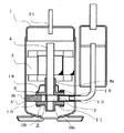
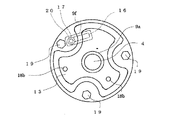
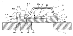
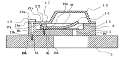
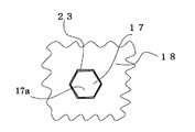
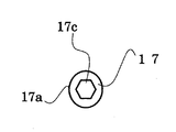
以下、この発明の実施の形態1を図1〜図4により説明する。図1はこの発明の実施の形態1における圧縮機を示す縦断面図である。図2は実施の形態1における圧縮機の圧縮機構部の模式的な平面図である。図3はこの発明の実施の形態1における圧縮機の吐出マフラー部分を上から見た平面図であり、シリンダ5の外形の記載を省略している。図4は実施の形態1における圧縮機の吐出ポート部分の縦断面図であり、下軸受10の記載を省略している。
次に、この発明の実施の形態2を図13により説明する。図13はこの発明の実施の形態2における圧縮機の吐出ポート部分の図4に相当する縦断面図である。なお、実施の形態1と同様部分については同一符号を付し、説明を省略する。また圧縮機の基本的な構成は図1及び図2と同様である。上記実施の形態1の図1〜図12の各例ではボルト17で吐出弁15及び吐出弁押え16を圧縮機構部2に締結固定するものを示したが、図13に示すように、ボルト17の代わりに、両側の端部26a,26bと足部26cを有するリベット26により、通し穴9eを通して吐出弁押え16と吐出弁15を上軸受9に締結固定し、リベット26の一方の端部である吐出弁押え16側の端部26aの上面を吐出マフラー18の吐出マフラー突起部20により上からリベット26の他方の端部である端部26b側へ押さえるようにしてもよい。このようにしても冷媒の液圧縮等の過剰な吐出方向への力が吐出弁15及び吐出弁押え16を介してリベット26の端部26aに加わっても端部26aが吐出ポート14の圧縮機構部2の外部側に消音空間を形成する吐出マフラー18に押さえられて端部26aが補強されるので、リベット26の破損が防止されるものが得られる。
モータ部3により駆動されて冷媒を圧縮する圧縮機構部2と、圧縮機構部2に設けられ圧縮された冷媒を圧縮機構部2の外部側へ吐出させる吐出ポート14と、吐出ポート14を開閉する吐出弁15と、吐出弁15を圧縮機構部2との間に挟み込むように吐出弁15に重ねて配置した吐出弁押え16と、吐出弁押え16及び吐出弁15を圧縮機構部2へ締結固定するボルト17と、圧縮機構部2に固定され吐出ポート14を覆うように設けられた吐出マフラー18と、を備え、ボルト17の締結が緩む方向へ回転しないように吐出マフラー18によりボルト17の頭部17aを押さえたので、冷媒の液圧縮等の過剰な圧縮が起こりボルト17に大きな負荷がかかった際にもボルト17が緩み難く、ボルト17の折損を防ぎ、高い信頼性を有する圧縮機を得ることができる。
Claims (7)
- モータ部により駆動されて冷媒を圧縮する圧縮機構部と、前記圧縮機構部に設けられ圧縮された冷媒を前記圧縮機構部の外部側へ吐出させる吐出ポートと、前記吐出ポートを開閉する吐出弁と、前記吐出弁を前記圧縮機構部との間に挟み込むように前記吐出弁に重ねて配置した吐出弁押えと、前記吐出弁押え及び前記吐出弁を前記圧縮機構部へ締結固定するボルトと、前記圧縮機構部に固定され前記吐出ポートを覆うように設けられた吐出マフラーと、を備え、前記ボルトの締結が緩む方向へ回転しないように前記吐出マフラーにより前記ボルトの頭部を押さえたことを特徴とする圧縮機。
- 前記吐出マフラーは、前記ボルトの前記頭部を前記ボルトのネジ部側へ押さえて前記ボルトの締結が緩む方向へ回転しないようにしたことを特徴とする請求項1に記載の圧縮機。
- 前記吐出マフラーは、前記ボルトの前記頭部を側方から押さえる係止片を備えて前記ボルトの締結が緩む方向へ回転しないようにしたことを特徴とする請求1に記載の圧縮機。
- 前記吐出マフラーは、前記ボルトの前記頭部を入り込ませて前記頭部を側方から押さえる系止穴を備えて前記ボルトの締結が緩む方向へ回転しないようにしたことを特徴とする請求1に記載の圧縮機。
- 前記吐出マフラーは、前記ボルトの前記頭部に形成された締結部に嵌合して前記頭部を押さえる係止部を備えて前記ボルトの締結が緩む方向へ回転しないようにしたことを特徴とする請求1に記載の圧縮機。
- モータ部により駆動されて冷媒を圧縮する圧縮機構部と、前記圧縮機構部に設けられ圧縮された冷媒を前記圧縮機構部の外部側へ吐出させる吐出ポートと、前記吐出ポートを開閉する吐出弁と、前記吐出弁を前記圧縮機構部との間に挟み込むように前記吐出弁に重ねて配置した吐出弁押えと、前記吐出弁押え及び前記吐出弁を前記圧縮機構部へ締結固定するリベットと、前記圧縮機構部に固定され前記吐出ポートを覆うように設けられた吐出マフラーと、を備え、前記吐出マフラーにより前記リベットの一方の端部を前記リベットの他方の端部側へ押さえたことを特徴とする圧縮機。
- 前記圧縮機構部はシリンダと、前記シリンダ内で回転して冷媒を圧縮するローリングピストンと、前記ローリングピストに接触するベーンと、回転軸を軸止する軸受部と前記シリンダの端面を閉塞する端板部を有する軸受と、を備えたロータリー方式であることを特徴とする請求項1から請求項6のいずれか1項に記載の圧縮機
Priority Applications (4)
| Application Number | Priority Date | Filing Date | Title |
|---|---|---|---|
| JP2014042902A JP2015169089A (ja) | 2014-03-05 | 2014-03-05 | 圧縮機 |
| CZ2015-138A CZ307718B6 (cs) | 2014-03-05 | 2015-02-26 | Kompresor |
| CN201520128005.2U CN204572466U (zh) | 2014-03-05 | 2015-03-05 | 压缩机 |
| CN201510098285.1A CN104895789B (zh) | 2014-03-05 | 2015-03-05 | 压缩机 |
Applications Claiming Priority (1)
| Application Number | Priority Date | Filing Date | Title |
|---|---|---|---|
| JP2014042902A JP2015169089A (ja) | 2014-03-05 | 2014-03-05 | 圧縮機 |
Publications (2)
| Publication Number | Publication Date |
|---|---|
| JP2015169089A true JP2015169089A (ja) | 2015-09-28 |
| JP2015169089A5 JP2015169089A5 (ja) | 2017-01-19 |
Family
ID=53865110
Family Applications (1)
| Application Number | Title | Priority Date | Filing Date |
|---|---|---|---|
| JP2014042902A Pending JP2015169089A (ja) | 2014-03-05 | 2014-03-05 | 圧縮機 |
Country Status (3)
| Country | Link |
|---|---|
| JP (1) | JP2015169089A (ja) |
| CN (2) | CN204572466U (ja) |
| CZ (1) | CZ307718B6 (ja) |
Cited By (1)
| Publication number | Priority date | Publication date | Assignee | Title |
|---|---|---|---|---|
| WO2018139354A1 (ja) | 2017-01-30 | 2018-08-02 | ダイキン工業株式会社 | 圧縮機 |
Families Citing this family (3)
| Publication number | Priority date | Publication date | Assignee | Title |
|---|---|---|---|---|
| JP2015169089A (ja) * | 2014-03-05 | 2015-09-28 | 三菱電機株式会社 | 圧縮機 |
| CN105351196A (zh) * | 2014-08-21 | 2016-02-24 | 洛阳中方实业有限公司 | 一种微型制冷压缩机 |
| JP7631150B2 (ja) * | 2021-08-31 | 2025-02-18 | 株式会社東芝 | 圧縮機、および空気調和機 |
Citations (5)
| Publication number | Priority date | Publication date | Assignee | Title |
|---|---|---|---|---|
| JPS57145794U (ja) * | 1981-03-10 | 1982-09-13 | ||
| JPS59169469U (ja) * | 1983-04-28 | 1984-11-13 | 三菱重工業株式会社 | リ−ド弁装置 |
| JPS62204011U (ja) * | 1986-06-17 | 1987-12-26 | ||
| JPH0218911U (ja) * | 1988-07-25 | 1990-02-08 | ||
| JPH10339270A (ja) * | 1997-06-05 | 1998-12-22 | Daewoo Electron Co Ltd | 圧縮機の弁結合体 |
Family Cites Families (15)
| Publication number | Priority date | Publication date | Assignee | Title |
|---|---|---|---|---|
| GB371688A (en) * | 1931-07-03 | 1932-04-28 | Paul Dugelay | Improvements in or relating to valve mechanism for high speed compressors |
| AT243420B (de) * | 1963-05-08 | 1965-11-10 | Enfo Grundlagen Forschungs Ag | Mehrringventil |
| JPS5759094A (en) * | 1980-09-26 | 1982-04-09 | Hitachi Ltd | Rotary compressor |
| JPS615373U (ja) * | 1984-06-15 | 1986-01-13 | 三洋電機株式会社 | 圧縮機の弁装置 |
| CS273498B1 (en) * | 1988-12-27 | 1991-03-12 | Tejkal Stanislav | Device for delivery valve's stroke definition |
| JPH0697035B2 (ja) * | 1989-02-21 | 1994-11-30 | 株式会社豊田自動織機製作所 | 往復式圧縮機 |
| US5709514A (en) * | 1996-05-30 | 1998-01-20 | Acadia Elastomers, Inc. | Liveload assembly |
| JPH109136A (ja) * | 1996-06-24 | 1998-01-13 | Toyota Autom Loom Works Ltd | 圧縮機 |
| US6079966A (en) * | 1997-11-18 | 2000-06-27 | Zexel Usa Corporation | Compressor housing |
| KR20020006311A (ko) * | 2000-07-12 | 2002-01-19 | 구자홍 | 로터리 압축기의 토출 밸브 장치 |
| KR20020054727A (ko) * | 2000-12-28 | 2002-07-08 | 구자홍 | 로터리 압축기의 토출밸브 진동 흡수장치 |
| JP4251239B2 (ja) * | 2007-07-25 | 2009-04-08 | ダイキン工業株式会社 | 密閉式圧縮機 |
| JP6020148B2 (ja) * | 2012-03-20 | 2016-11-02 | 株式会社豊田自動織機 | 電動圧縮機 |
| JP2014194211A (ja) * | 2013-03-01 | 2014-10-09 | Aisan Ind Co Ltd | 電動バキュームポンプ |
| JP2015169089A (ja) * | 2014-03-05 | 2015-09-28 | 三菱電機株式会社 | 圧縮機 |
-
2014
- 2014-03-05 JP JP2014042902A patent/JP2015169089A/ja active Pending
-
2015
- 2015-02-26 CZ CZ2015-138A patent/CZ307718B6/cs not_active IP Right Cessation
- 2015-03-05 CN CN201520128005.2U patent/CN204572466U/zh not_active Expired - Lifetime
- 2015-03-05 CN CN201510098285.1A patent/CN104895789B/zh not_active Expired - Fee Related
Patent Citations (5)
| Publication number | Priority date | Publication date | Assignee | Title |
|---|---|---|---|---|
| JPS57145794U (ja) * | 1981-03-10 | 1982-09-13 | ||
| JPS59169469U (ja) * | 1983-04-28 | 1984-11-13 | 三菱重工業株式会社 | リ−ド弁装置 |
| JPS62204011U (ja) * | 1986-06-17 | 1987-12-26 | ||
| JPH0218911U (ja) * | 1988-07-25 | 1990-02-08 | ||
| JPH10339270A (ja) * | 1997-06-05 | 1998-12-22 | Daewoo Electron Co Ltd | 圧縮機の弁結合体 |
Cited By (2)
| Publication number | Priority date | Publication date | Assignee | Title |
|---|---|---|---|---|
| WO2018139354A1 (ja) | 2017-01-30 | 2018-08-02 | ダイキン工業株式会社 | 圧縮機 |
| US11971037B2 (en) | 2017-01-30 | 2024-04-30 | Daikin Industries, Ltd. | Drive shaft of compressor having oil groove portion and oil sump |
Also Published As
| Publication number | Publication date |
|---|---|
| CZ2015138A3 (cs) | 2015-11-04 |
| CZ307718B6 (cs) | 2019-03-20 |
| CN104895789B (zh) | 2017-04-12 |
| CN104895789A (zh) | 2015-09-09 |
| CN204572466U (zh) | 2015-08-19 |
Similar Documents
| Publication | Publication Date | Title |
|---|---|---|
| CN105705790B (zh) | 压缩机 | |
| CN206221211U (zh) | 吸排气阀组件及具有其的往复式压缩机 | |
| CN204572466U (zh) | 压缩机 | |
| JP6727300B2 (ja) | ロータリー圧縮機 | |
| CN104884808B (zh) | 螺杆压缩机 | |
| JP4638762B2 (ja) | スクロール圧縮機 | |
| CN101326370A (zh) | 旋转式压缩机 | |
| JP2009047018A (ja) | 圧縮機 | |
| JP6926745B2 (ja) | 圧縮機 | |
| WO2016052318A1 (ja) | 往復動式圧縮機 | |
| KR100608862B1 (ko) | 스크롤 압축기의 체크밸브장치 | |
| JP2019132254A (ja) | 回転式圧縮機、および冷凍サイクル装置 | |
| JP7418190B2 (ja) | ロータリ圧縮機 | |
| CN102562537A (zh) | 一种压缩机 | |
| JP2009047017A (ja) | 圧縮機 | |
| JP4595942B2 (ja) | 圧縮機 | |
| JP2014129796A (ja) | 圧縮機 | |
| CN204312358U (zh) | 用于旋转式压缩机的压缩机构及具有其的旋转式压缩机 | |
| CN1782432A (zh) | 旋转式双压缸压缩机的下消音器结构 | |
| CN104481882A (zh) | 用于旋转式压缩机的压缩机构及具有其的旋转式压缩机 | |
| CN100412377C (zh) | 旋转式压缩机 | |
| JP5195224B2 (ja) | 密閉型圧縮機 | |
| CN202545251U (zh) | 压缩单元和压缩机 | |
| JP2010031690A (ja) | ロータリ圧縮機 | |
| CN1782420B (zh) | 涡卷式压缩机的止回阀装置 |
Legal Events
| Date | Code | Title | Description |
|---|---|---|---|
| A521 | Request for written amendment filed |
Free format text: JAPANESE INTERMEDIATE CODE: A523 Effective date: 20161206 |
|
| A621 | Written request for application examination |
Free format text: JAPANESE INTERMEDIATE CODE: A621 Effective date: 20161206 |
|
| A977 | Report on retrieval |
Free format text: JAPANESE INTERMEDIATE CODE: A971007 Effective date: 20170914 |
|
| A131 | Notification of reasons for refusal |
Free format text: JAPANESE INTERMEDIATE CODE: A131 Effective date: 20170926 |
|
| A02 | Decision of refusal |
Free format text: JAPANESE INTERMEDIATE CODE: A02 Effective date: 20180403 |