JP2015172902A - Paper sheet transport device - Google Patents
Paper sheet transport device Download PDFInfo
- Publication number
- JP2015172902A JP2015172902A JP2014049181A JP2014049181A JP2015172902A JP 2015172902 A JP2015172902 A JP 2015172902A JP 2014049181 A JP2014049181 A JP 2014049181A JP 2014049181 A JP2014049181 A JP 2014049181A JP 2015172902 A JP2015172902 A JP 2015172902A
- Authority
- JP
- Japan
- Prior art keywords
- conveyance
- guide
- storage
- transport
- installation surface
- Prior art date
- Legal status (The legal status is an assumption and is not a legal conclusion. Google has not performed a legal analysis and makes no representation as to the accuracy of the status listed.)
- Pending
Links
Images




Abstract
Description
本発明は、紙葉搬送装置に関し、より詳細には、搬送路を通じて搬送された紙幣等の紙葉を、紙葉収納装置に送出して収納させる装置に関するものである。 The present invention relates to a paper sheet transport device, and more particularly to a device for sending and storing paper sheets such as banknotes transported through a transport path to a paper sheet storage device.
複数の遊技機を並設した遊技機列を備える遊技島では、遊技機の間に設けられた遊技媒体貸出機から投入される紙幣の回収作業を容易化するため、遊技機の背面側に搬送装置を設けるようにしている。搬送装置は、遊技媒体貸出機の背面を通過するように構成された搬送路を備えたもので、搬送路の下流端部が遊技島の端部に設置された紙幣収納装置に接続されている(例えば、特許文献1参照)。ここで搬送路は、例えば搬送チェーンの駆動によって紙幣を下流に搬送させるものである。遊技島に設けられる搬送装置では、紙幣を横長起立姿勢で搬送するように構成されているのが一般的である。また、上記搬送装置においては、上記搬送路と、紙幣収納装置を設置する収納設置面とが直角となるのが一般的である。 On a gaming island with a row of gaming machines with a plurality of gaming machines arranged side by side, it is transported to the back side of the gaming machines to facilitate the collection of banknotes inserted from gaming medium lending machines provided between the gaming machines. A device is provided. The transport device includes a transport path configured to pass through the back of the game medium lending machine, and a downstream end portion of the transport path is connected to a banknote storage device installed at an end portion of the game island. (For example, refer to Patent Document 1). Here, the conveyance path is for conveying bills downstream, for example, by driving a conveyance chain. Generally, the transport device provided on the amusement island is configured to transport bills in a horizontally long standing posture. Moreover, in the said conveying apparatus, it is common that the said conveyance path and the storage installation surface which installs a banknote storage apparatus become a right angle.
ところが、上述した搬送装置においては、搬送路と収納設置面とが直角であったために、次のような問題があった。 However, the above-described transport apparatus has the following problems because the transport path and the storage installation surface are at right angles.
近年、遊技機を設置した店舗では、他の店舗との差別化を図るために、遊技機を直線上に設置するだけでなく、カーブさせて設置させることがある。このような場合、搬送路と収納設置面とが直角なものとならないため、上述した搬送装置を適用する際に、紙幣収納装置の紙幣入口を有する面が搬送路に対して直交するようスペーサを介在させて紙幣収納装置を収納設置面に配設したり、搬送路の途中に搬送方向を変更する可変搬送路を配設したりする必要があり、部品点数の増大による製造コストの増大化を招来していた。 In recent years, in a store where a gaming machine is installed, in order to differentiate from other stores, the gaming machine may be installed not only on a straight line but also on a curve. In such a case, since the conveyance path and the storage installation surface are not perpendicular to each other, when the above-described conveyance device is applied, the spacer is arranged so that the surface having the banknote entrance of the banknote storage device is orthogonal to the conveyance path. It is necessary to arrange the bill storage device on the storage installation surface by interposing it, or to arrange a variable conveyance path that changes the conveyance direction in the middle of the conveyance path, and increase the manufacturing cost by increasing the number of parts I was invited.
本発明は、上記実情に鑑みて、製造コストを増大させることなく設置自由度の向上を図ることができる紙幣搬送装置を提供することを目的とする。 An object of this invention is to provide the banknote conveying apparatus which can aim at the improvement of installation freedom, without increasing manufacturing cost in view of the said situation.
上記目的を達成するため、本発明に係る紙葉搬送装置は、自身に形成された搬送開口が収納設置面に形成された収納開口に連通する態様で該収納設置面に取り付けられた接続部材と、前記接続部材に配設され、かつ搬送路を通じて搬送された紙葉が前記搬送開口及び前記収納開口を通過するよう案内するガイド機構とを備え、前記収納設置面に配設された紙葉収納装置に紙葉を送出して収納させる紙葉搬送装置であって、前記接続部材は、鉛直方向に沿って延在し、かつ自身の中心を軸心としてその軸心回りに回転することで前記搬送路の内部に配設された搬送走行体を走行させる搬送軸に軸受部材を介して該搬送軸回りに変位可能となる態様で配設されることで、前記収納設置面に対する前記搬送路の延在角度を可変としたことを特徴とする。 In order to achieve the above object, the paper sheet transport device according to the present invention includes a connection member attached to the storage installation surface in a mode in which the transport opening formed in the communication port communicates with the storage opening formed in the storage installation surface. And a guide mechanism for guiding the paper sheet, which is disposed on the connection member and transported through the transport path, to pass through the transport opening and the storage opening, and stores the paper sheet on the storage installation surface. A paper sheet conveying apparatus for sending and storing a paper sheet in the apparatus, wherein the connection member extends along a vertical direction and rotates about its own axis as an axis to rotate the axis. By being arranged in a mode that can be displaced around the conveyance axis via a bearing member on the conveyance axis that travels the conveyance traveling body arranged inside the conveyance path, the conveyance path with respect to the storage installation surface Characterized by variable extension angle .
また本発明は、上記紙葉搬送装置において、前記ガイド機構は、自身に形成された突片が前記搬送路を構成する搬送ガイドに形成されたスリットに進入した形態で該搬送ガイドに係合し、かつ該搬送ガイドとともに形成する円弧状搬送部分の延在長さを可変とした送出ガイドを備えたことを特徴とする。 Further, the present invention is the paper sheet transport apparatus, wherein the guide mechanism engages with the transport guide in a form in which a protrusion formed on the guide mechanism enters a slit formed in the transport guide constituting the transport path. And a delivery guide having a variable extension length of an arcuate conveyance portion formed with the conveyance guide.
本発明によれば、接続部材が搬送軸に軸受部材を介して該搬送軸回りに変位可能となる態様で配設されることで収納設置面に対する搬送路の延在角度を可変としたので、従来のようにスペーサ等の部品を必要とせずに部品点数の増大化を抑制でき、これにより、製造コストを増大させることなく設置自由度の向上を図ることができるという効果を奏する。 According to the present invention, since the connection member is arranged in a manner that can be displaced around the conveyance axis via the bearing member on the conveyance axis, the extension angle of the conveyance path with respect to the storage installation surface is made variable. As in the prior art, an increase in the number of parts can be suppressed without requiring parts such as spacers, and this provides an effect that the degree of freedom in installation can be improved without increasing the manufacturing cost.
以下、添付図面を参照しながら本発明に係る紙葉搬送装置の好適な実施の形態について詳細に説明する。 DESCRIPTION OF EMBODIMENTS Hereinafter, a preferred embodiment of a paper sheet transport device according to the present invention will be described in detail with reference to the accompanying drawings.
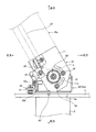
図1は、本発明の実施の形態である紙葉搬送装置の要部を示した平面図である。ここで例示する紙葉搬送装置は、遊技島において複数の紙幣投入処理機から投入された紙幣を、遊技島の端部における収納設置面1に配設された紙幣収納装置(紙葉収納装置)2に一括して収納すべく搬送する装置(以下、「紙幣搬送装置」という)として用いられるものである。収納設置面1には収納開口1aが形成されている。かかる紙幣搬送装置は、支持部材10と接続部材30とを備えて構成されている。
FIG. 1 is a plan view showing a main part of a paper sheet conveying apparatus according to an embodiment of the present invention. The paper sheet conveying apparatus illustrated here is a banknote storage apparatus (paper sheet storage apparatus) in which banknotes inserted from a plurality of banknote insertion processing machines on amusement islands are arranged on the
支持部材10は、搬送路10aの一部を構成するもので、例えば板金を屈曲加工等して形成されたものである。ここで搬送路10aは、1つの遊技島における遊技機列の相互間に確保されたスペースに配設されるものであり、図1の例では搬送路10aの延在角度は、収納設置面1に対して直交している。
The
上記支持部材10は、図2に示すように、上面11及び下面12にて軸受部材(図示せず)を介して搬送軸20を支持するものである。搬送軸20は、鉛直方向に沿って延在するものであり、モータ等の駆動機構21により駆動力が伝達されることで自身の中心を軸心としてその軸心回りに回転可能なものである。この搬送軸20の中央部分には、スプロケット22が配設されている。スプロケット22は、詳細は明示しないが、無端状に張設された搬送走行体23の一部と噛み合い、該搬送走行体23を走行させるものである。搬送走行体23は、搬送路10aの内部に配設されており、搬送軸20の回転により走行することで搬送路10aの内部に設定された図示せぬ搬送ガイド面との間で紙幣を挟んだ状態にして紙幣の搬送を行うものである。
As shown in FIG. 2, the
また、上記支持部材10の上面11には、搬送軸20を中心として円弧状に延在する複数(図示の例では2つ)の長孔11aが形成されている。また、支持部材10の下面12にも、図には明示しないが、上面11に形成された長孔11aの対応箇所に同形状の長孔が形成されている。
In addition, a plurality of (two in the illustrated example)
接続部材30は、図3にも示すように、第1接続板金30aと第2接続板金30bとを備えて構成されている。
As shown in FIG. 3, the
第1接続板金30aは、上面31及び下面32が右側面33を介して連結されて形成されており、上面31及び下面32の互いに対応する箇所には、多角形状(図示の例では8角形状)の貫通孔31a,32aが形成されている。また、上面31の前端部分には上方に向けて延在する上延部31bが形成されており、下面32の前端部分には下方に向けて延在する下延部32bが形成されている。
The first
第2接続板金30bは、上下方向に沿って延在する長尺状のものであり、その前端部分の中央領域に左方に向けて突出する舌片状の取付片34が設けられている。この第2接続板金30bは、その上端部分及び下端部分が第1接続板金30aの上面31及び下面32の左端部に取り付けられている。このように第2接続板金30bが第1接続板金30aに取り付けられることで、接続部材30には、前方側において矩形状の搬送開口35が形成されている。
The second
このような接続部材30は、第1接続板金30aの上面31が支持部材10の上面11の下方側に位置し、第1接続板金30aの下面32が支持部材10の下面12の上方側に位置した状態で、各貫通孔31a,32aにベアリング等の軸受部材36を介して上記搬送軸20を貫通させている。
In such a
そして、接続部材30は、第1接続板金30aの上面31及び下面32に形成されたネジ孔31c,32cに支持部材10の長孔11aを貫通する雄ネジ40が進入して互いに螺合することで該支持部材10に係合されている。これにより、接続部材30は、搬送軸20回りに変位可能であるとともに、支持部材10に対して長孔11aの延在長さの分だけ相対的に変位可能な態様で配設されている。
And the
上記接続部材30には、図4及び図5に示すようなガイド機構50が配設されている。ガイド機構50は、送出ガイド50aと誘導ガイド50bとを備えて構成されている。
The
送出ガイド50aは、例えば樹脂材等により形成されるもので、図6にも示すように、上面51と下面52との間の中央部53が湾曲状を成している。この送出ガイド50aは、中央部53より左方に向けて突出する舌片状の固定片54が第2接続板金30bの取付片34の前方側に位置した状態でビス等により取り付けられて固定されている。また、送出ガイド50aの前端部分は、搬送開口35を通過して前方側に突出している。
The
送出ガイド50aの中央部53の内壁面には、複数(例えば4つ)の突片53aが上下に所定間隔毎に形成されている。これら突片53aは、上記搬送路10aを構成し、かつ支持部材10に支持される搬送ガイド24に形成されたスリット24aに進入しており、これにより送出ガイド50aは、搬送ガイド24に係合している。このような送出ガイド50aは、搬送ガイド24とともに円弧状搬送部分60を形成している。
On the inner wall surface of the
誘導ガイド50bは、例えば樹脂材等により形成されるもので、送出ガイド50aと対となるものである。この誘導ガイド50bは、上面55の左端部分に形成された取付部55aと、下面56の左端部分に形成された取付部56aとが第2接続板金30bを介して第1接続板金30aに取り付けられることで配設されている。
The
このような誘導ガイド50bは、前端部分が送出ガイド50aの前端部分とともに矩形状の搬出口60aを形成している。また、誘導ガイド50bは、誘導片57が上下の2箇所に形成されている。誘導片57は、後方に向けて延在した後に右方に向けて湾曲した形状を成しており、搬送路10aを通過して搬送ガイド24まで至った紙幣を円弧状搬送部分60に誘導するものである。
In such a
このようなガイド機構50を有する接続部材30は、第1接続板金30aの上延部31b及び下延部32bが収納設置面1に締結部材を介して締結されることで、搬送開口35が収納開口1aに連通する態様で収納設置面1に取り付けられている。そのため、送出ガイド50aと誘導ガイド50bとにより形成される搬出口60aも収納開口1aに連通している。
The
以上のような構成を有する紙幣搬送装置においては、駆動機構21により駆動力が伝達されることにより搬送軸20が回転すると、搬送走行体23が走行し、これにより搬送路10aを紙幣が横長起立姿勢で搬送される。搬送路10aを搬送された紙幣は、その後に誘導ガイド50bの誘導片57により円弧状搬送部分60に至って誘導ガイド50bと送出ガイド50aとの間を通過し、そして、搬出口60aから送出されることで、搬送開口35及び収納開口1aを通過して紙幣収納装置2に収納される。
In the banknote transport apparatus having the above configuration, when the
そして、上記紙幣搬送装置では、接続部材30が搬送軸20回りに変位可能であるとともに、支持部材10に対して長孔11aの延在長さの分だけ相対的に変位可能な態様で配設されているので、次のように搬送路10aを変位させることができる。
And in the said banknote conveying apparatus, while the
すなわち、図7に示すように、支持部材10を含む搬送路10aを搬送軸20を中心として時計回りに所定角度だけ変位させることができる。より詳細には、支持部材10の長孔11aを貫通した状態で接続部材30のネジ孔31c,32cに螺合する雄ネジ40を回転させて該ネジ孔31c,32cとの噛み合いを緩め、接続部材30は収納設置面1に取り付けられているから、支持部材10を搬送路10aとともに所定角度だけ変位させ、その後に雄ネジ40をネジ孔31c,32cに螺合させればよい。これにより収納設置面1に対する搬送路10aの延在角度を変更させることができる。
That is, as shown in FIG. 7, the
この場合において、ガイド機構50においては、図8及び図9に示すように、送出ガイド50aの突片53aが搬送ガイド24のスリット24aに進入した状態で互いの位置が相対的に変位し、送出ガイド50aと搬送ガイド24とで形成する円弧状搬送部分60の延在長さを長大化させることができる。つまり、送出ガイド50aは、搬送ガイド24と形成する円弧状搬送部分60の延在長さを可変とするものである。
In this case, in the
このように設置された紙幣搬送装置においても、駆動機構21により駆動力が伝達されることにより搬送軸20が回転すると、搬送走行体23が走行し、これにより搬送路10aを紙幣が横長起立姿勢で搬送される。搬送路10aを搬送された紙幣は、その後に誘導ガイド50bの誘導片57により円弧状搬送部分60に至って誘導ガイド50bと送出ガイド50aとの間を通過し、そして、搬出口60aから送出されることで、搬送開口35及び収納開口1aを通過して紙幣収納装置2に収納される。
Also in the banknote transport apparatus installed in this way, when the
また、本発明の実施の形態である紙幣搬送装置においては、上記送出ガイド50aの代わりに図10に示すような第2送出ガイド50a′を用いてガイド機構50′を構成するようにしてもよい。
Moreover, in the banknote conveyance apparatus which is embodiment of this invention, you may make it comprise guide mechanism 50 'using the
第2送出ガイド50a′は、上記送出ガイド50aと同様に、例えば樹脂材等により形成されるもので、上面51′と下面52′との間の中央部53′が湾曲状を成している。この第2送出ガイド50a′は、上記送出ガイド50aに対して中央部53′の延在方向及び長さが異なるものである。
Similarly to the
そして、第2送出ガイド50a′の中央部53′の内壁面には、複数(例えば4つ)の突片53a′が上下に所定間隔毎に形成されている。これら突片53a′は、搬送ガイド24に形成されたスリット24aに進入しており、これにより第2送出ガイド50a′は、搬送ガイド24に係合している。このような第2送出ガイド50a′は、搬送ガイド24とともに円弧状搬送部分60′を形成している。
A plurality (for example, four) of projecting
このような第2送出ガイド50a′を用いた紙幣搬送装置では、図11に示すように、図1の状態に対して支持部材10を含む搬送路10aを搬送軸20を中心として反時計回りに所定角度だけ変位させることができる。より詳細には、支持部材10の長孔11aを貫通した状態で接続部材30のネジ孔31c,32cに螺合する雄ネジ40を回転させて該ネジ孔31c,32cとの噛み合いを緩め、接続部材30は収納設置面1に取り付けられているから、支持部材10を搬送路10aとともに所定角度だけ変位させ、その後に雄ネジ40をネジ孔31c,32cに螺合させればよい。これにより収納設置面1に対する搬送路10aの延在角度を変更させることができる。
In the banknote transport apparatus using the
この場合において、ガイド機構50′においては、図12及び図13に示すように、第2送出ガイド50a′の突片53a′が搬送ガイド24のスリット24aに進入した状態で互いの位置が相対的に変位し、第2送出ガイド50a′と搬送ガイド24とで形成する円弧状搬送部分60′の延在長さを可変させることができる。
In this case, in the guide mechanism 50 ', the relative positions of the
このように設置された紙幣搬送装置においても、駆動機構21により駆動力が伝達されることにより搬送軸20が回転すると、搬送走行体23が走行し、これにより搬送路10aを紙幣が横長起立姿勢で搬送される。搬送路10aを搬送された紙幣は、その後に誘導ガイド50bの誘導片57により円弧状搬送部分60′に至って誘導ガイド50bと送出ガイド50aとの間を通過し、そして、搬出口60a′から送出されることで、搬送開口35及び収納開口1aを通過して紙幣収納装置2に収納される。
Also in the banknote transport apparatus installed in this way, when the
以上説明したように、本実施の形態である紙幣搬送装置によれば、接続部材30が搬送軸20回りに変位可能となる態様で配設されることで収納設置面1に対する搬送路10aの延在角度を可変としたので、従来のようにスペーサ等の部品を必要とせずに部品点数の増大化を抑制でき、これにより、製造コストを増大させることなく設置自由度の向上を図ることができる。
As described above, according to the banknote transport apparatus according to the present embodiment, the
上記紙幣搬送装置によれば、ガイド機構50(50′)を構成する送出ガイド50aが、突片53a(53a′)が搬送ガイド24に形成されたスリット24aに進入した形態で該搬送ガイド24に係合し、かつ該搬送ガイド24とともに形成する円弧状搬送部分60(60′)の延在長さを可変としたので、これによっても設置自由度の向上を図ることができる。
According to the banknote transport apparatus, the
以上、本発明の好適な実施の形態について説明したが、本発明はこれに限定されるものではなく、種々の変更を行うことができる。 The preferred embodiment of the present invention has been described above, but the present invention is not limited to this, and various modifications can be made.
上述した実施の形態では、接続部材30が第1接続板金30aと第2接続板金30bとにより構成されていたが、本発明においては、接続部材は、搬送開口が形成され、かつ収納設置面に取り付けられるものであれば、その形態等については特に限定されるものではない。
In the above-described embodiment, the
1 収納設置面
1a 収納開口
2 紙幣収納装置(紙葉収納装置)
10 支持部材
10a 搬送路
11 上面
11a 長孔
12 下面
20 搬送軸
21 駆動機構
22 スプロケット
23 搬送走行体
24 搬送ガイド
24a スリット
30 接続部材
30a 第1接続板金
30b 第2接続板金
31 上面
32 下面
33 右側面
35 搬送開口
36 軸受部材
40 雄ネジ
50 ガイド機構
50a 送出ガイド
50b 誘導ガイド
53a 突片
57 誘導片
60 円弧状搬送部分
60a 搬出口
DESCRIPTION OF
DESCRIPTION OF
Claims (2)
前記接続部材に配設され、かつ搬送路を通じて搬送された紙葉が前記搬送開口及び前記収納開口を通過するよう案内するガイド機構と
を備え、
前記収納設置面に配設された紙葉収納装置に紙葉を送出して収納させる紙葉搬送装置であって、
前記接続部材は、鉛直方向に沿って延在し、かつ自身の中心を軸心としてその軸心回りに回転することで前記搬送路の内部に配設された搬送走行体を走行させる搬送軸に軸受部材を介して該搬送軸回りに変位可能となる態様で配設されることで、前記収納設置面に対する前記搬送路の延在角度を可変としたことを特徴とする紙葉搬送装置。 A connection member attached to the storage installation surface in a mode in which the conveyance opening formed in itself communicates with the storage opening formed in the storage installation surface;
A guide mechanism that is disposed on the connection member and guides a paper sheet conveyed through a conveyance path so as to pass through the conveyance opening and the storage opening;
A paper sheet transporting device for sending and storing paper sheets to a paper sheet storage device disposed on the storage installation surface,
The connection member extends along a vertical direction, and rotates around the axis centered on the center of the connection member so as to travel a transport traveling body disposed inside the transport path. A paper sheet conveying apparatus characterized in that the extending angle of the conveying path with respect to the storage and installation surface is variable by being arranged in a manner that can be displaced around the conveying axis via a bearing member.
Priority Applications (1)
| Application Number | Priority Date | Filing Date | Title |
|---|---|---|---|
| JP2014049181A JP2015172902A (en) | 2014-03-12 | 2014-03-12 | Paper sheet transport device |
Applications Claiming Priority (1)
| Application Number | Priority Date | Filing Date | Title |
|---|---|---|---|
| JP2014049181A JP2015172902A (en) | 2014-03-12 | 2014-03-12 | Paper sheet transport device |
Publications (1)
| Publication Number | Publication Date |
|---|---|
| JP2015172902A true JP2015172902A (en) | 2015-10-01 |
Family
ID=54260174
Family Applications (1)
| Application Number | Title | Priority Date | Filing Date |
|---|---|---|---|
| JP2014049181A Pending JP2015172902A (en) | 2014-03-12 | 2014-03-12 | Paper sheet transport device |
Country Status (1)
| Country | Link |
|---|---|
| JP (1) | JP2015172902A (en) |
Citations (4)
| Publication number | Priority date | Publication date | Assignee | Title |
|---|---|---|---|---|
| JPH01288540A (en) * | 1988-05-14 | 1989-11-20 | Kiyoto Uchida | Transporting device for thin plate body |
| US5503383A (en) * | 1994-06-27 | 1996-04-02 | Kabushiki Kaisha Ace Denken | Ground mechanism for a paper strip conveying mechanism |
| JP2003221144A (en) * | 2002-01-29 | 2003-08-05 | Sanyo Electric Co Ltd | Thin section conveying device and its utilization device |
| JP2004081249A (en) * | 2002-08-22 | 2004-03-18 | Sayama Precision Ind Co | Paper sheet conveyor device |
-
2014
- 2014-03-12 JP JP2014049181A patent/JP2015172902A/en active Pending
Patent Citations (4)
| Publication number | Priority date | Publication date | Assignee | Title |
|---|---|---|---|---|
| JPH01288540A (en) * | 1988-05-14 | 1989-11-20 | Kiyoto Uchida | Transporting device for thin plate body |
| US5503383A (en) * | 1994-06-27 | 1996-04-02 | Kabushiki Kaisha Ace Denken | Ground mechanism for a paper strip conveying mechanism |
| JP2003221144A (en) * | 2002-01-29 | 2003-08-05 | Sanyo Electric Co Ltd | Thin section conveying device and its utilization device |
| JP2004081249A (en) * | 2002-08-22 | 2004-03-18 | Sayama Precision Ind Co | Paper sheet conveyor device |
Similar Documents
| Publication | Publication Date | Title |
|---|---|---|
| JP2025019335A (en) | Island Facilities | |
| US8453829B1 (en) | High performance washing inducing transfer unit using wire connected roller | |
| JP4349101B2 (en) | Substrate transfer device | |
| JP5777066B2 (en) | Banknote transfer device | |
| JP2014177683A (en) | Substrate conveyance tray and deposition apparatus | |
| JP2020505291A5 (en) | ||
| JPWO2018003325A1 (en) | Front and back reversing device, sheet processing machine and front and back reversing method | |
| JP6482756B2 (en) | Paper sheet transport device | |
| JP2014210638A (en) | Card conveying device | |
| JP5838128B2 (en) | Transport device | |
| JP2017178588A (en) | Conveying apparatus | |
| JP5612414B2 (en) | Banknote posture change device | |
| JP4233410B2 (en) | Banknote transfer device | |
| JP5641171B2 (en) | Medals transport path | |
| KR20090053982A (en) | Display Board Transfer Guide Device | |
| KR200425595Y1 (en) | Banknote Transfer Device | |
| JP3996013B2 (en) | Bill delivery device | |
| CN215416738U (en) | Automatic ticket vending machine and material conveying mechanism | |
| JP2002326736A (en) | Bill transporter | |
| JP6221640B2 (en) | Paper sheet storage device | |
| JP2005343682A (en) | Paper sheet conveyance device | |
| JP4705617B2 (en) | Paper piece conveyor | |
| JP4197348B2 (en) | Game ball lifting device | |
| JP2004081249A (en) | Paper sheet conveyor device | |
| JP6594756B2 (en) | Coin feeding mechanism and coin processing device |
Legal Events
| Date | Code | Title | Description |
|---|---|---|---|
| A621 | Written request for application examination |
Free format text: JAPANESE INTERMEDIATE CODE: A621 Effective date: 20160323 |
|
| A977 | Report on retrieval |
Free format text: JAPANESE INTERMEDIATE CODE: A971007 Effective date: 20170206 |
|
| A131 | Notification of reasons for refusal |
Free format text: JAPANESE INTERMEDIATE CODE: A131 Effective date: 20170214 |
|
| A02 | Decision of refusal |
Free format text: JAPANESE INTERMEDIATE CODE: A02 Effective date: 20170919 |