JP2015190863A - Pressure detector - Google Patents
Pressure detector Download PDFInfo
- Publication number
- JP2015190863A JP2015190863A JP2014068451A JP2014068451A JP2015190863A JP 2015190863 A JP2015190863 A JP 2015190863A JP 2014068451 A JP2014068451 A JP 2014068451A JP 2014068451 A JP2014068451 A JP 2014068451A JP 2015190863 A JP2015190863 A JP 2015190863A
- Authority
- JP
- Japan
- Prior art keywords
- piezoelectric sheet
- sheet
- piezoelectric
- adhesive layer
- pressure detector
- Prior art date
- Legal status (The legal status is an assumption and is not a legal conclusion. Google has not performed a legal analysis and makes no representation as to the accuracy of the status listed.)
- Pending
Links
- 238000001514 detection method Methods 0.000 claims abstract description 125
- 239000012790 adhesive layer Substances 0.000 claims abstract description 86
- 239000000853 adhesive Substances 0.000 claims description 13
- 230000001070 adhesive effect Effects 0.000 claims description 13
- 239000000758 substrate Substances 0.000 abstract description 37
- 239000011521 glass Substances 0.000 abstract description 23
- 238000003825 pressing Methods 0.000 abstract description 23
- 230000035945 sensitivity Effects 0.000 abstract description 17
- 230000035882 stress Effects 0.000 description 57
- 239000011347 resin Substances 0.000 description 30
- 229920005989 resin Polymers 0.000 description 30
- 239000010408 film Substances 0.000 description 28
- 239000000463 material Substances 0.000 description 23
- 230000000694 effects Effects 0.000 description 21
- 238000004088 simulation Methods 0.000 description 11
- 238000007740 vapor deposition Methods 0.000 description 7
- 229910052751 metal Inorganic materials 0.000 description 6
- 239000002184 metal Substances 0.000 description 6
- 238000007650 screen-printing Methods 0.000 description 6
- 239000002033 PVDF binder Substances 0.000 description 5
- BQCADISMDOOEFD-UHFFFAOYSA-N Silver Chemical compound [Ag] BQCADISMDOOEFD-UHFFFAOYSA-N 0.000 description 5
- 238000004364 calculation method Methods 0.000 description 5
- 238000000034 method Methods 0.000 description 5
- 229920002981 polyvinylidene fluoride Polymers 0.000 description 5
- RYGMFSIKBFXOCR-UHFFFAOYSA-N Copper Chemical compound [Cu] RYGMFSIKBFXOCR-UHFFFAOYSA-N 0.000 description 4
- 239000004020 conductor Substances 0.000 description 4
- 229910052802 copper Inorganic materials 0.000 description 4
- 239000010949 copper Substances 0.000 description 4
- 239000010410 layer Substances 0.000 description 4
- 229910052709 silver Inorganic materials 0.000 description 4
- 239000004332 silver Substances 0.000 description 4
- OKTJSMMVPCPJKN-UHFFFAOYSA-N Carbon Chemical compound [C] OKTJSMMVPCPJKN-UHFFFAOYSA-N 0.000 description 3
- 101150107050 PSA2 gene Proteins 0.000 description 3
- 101150045091 PSA3 gene Proteins 0.000 description 3
- 229920001609 Poly(3,4-ethylenedioxythiophene) Polymers 0.000 description 3
- 229910052451 lead zirconate titanate Inorganic materials 0.000 description 3
- 230000003287 optical effect Effects 0.000 description 3
- 230000010287 polarization Effects 0.000 description 3
- IUVCFHHAEHNCFT-INIZCTEOSA-N 2-[(1s)-1-[4-amino-3-(3-fluoro-4-propan-2-yloxyphenyl)pyrazolo[3,4-d]pyrimidin-1-yl]ethyl]-6-fluoro-3-(3-fluorophenyl)chromen-4-one Chemical compound C1=C(F)C(OC(C)C)=CC=C1C(C1=C(N)N=CN=C11)=NN1[C@@H](C)C1=C(C=2C=C(F)C=CC=2)C(=O)C2=CC(F)=CC=C2O1 IUVCFHHAEHNCFT-INIZCTEOSA-N 0.000 description 2
- PXHVJJICTQNCMI-UHFFFAOYSA-N Nickel Chemical compound [Ni] PXHVJJICTQNCMI-UHFFFAOYSA-N 0.000 description 2
- 239000004820 Pressure-sensitive adhesive Substances 0.000 description 2
- XLOMVQKBTHCTTD-UHFFFAOYSA-N Zinc monoxide Chemical compound [Zn]=O XLOMVQKBTHCTTD-UHFFFAOYSA-N 0.000 description 2
- 239000002041 carbon nanotube Substances 0.000 description 2
- 229910021393 carbon nanotube Inorganic materials 0.000 description 2
- 229920001940 conductive polymer Polymers 0.000 description 2
- AMGQUBHHOARCQH-UHFFFAOYSA-N indium;oxotin Chemical compound [In].[Sn]=O AMGQUBHHOARCQH-UHFFFAOYSA-N 0.000 description 2
- 230000007257 malfunction Effects 0.000 description 2
- 238000012986 modification Methods 0.000 description 2
- 230000004048 modification Effects 0.000 description 2
- 230000002265 prevention Effects 0.000 description 2
- 230000001681 protective effect Effects 0.000 description 2
- BNEMLSQAJOPTGK-UHFFFAOYSA-N zinc;dioxido(oxo)tin Chemical compound [Zn+2].[O-][Sn]([O-])=O BNEMLSQAJOPTGK-UHFFFAOYSA-N 0.000 description 2
- 229920000178 Acrylic resin Polymers 0.000 description 1
- 239000004925 Acrylic resin Substances 0.000 description 1
- 229930182556 Polyacetal Natural products 0.000 description 1
- 239000002042 Silver nanowire Substances 0.000 description 1
- 238000003848 UV Light-Curing Methods 0.000 description 1
- NIXOWILDQLNWCW-UHFFFAOYSA-N acrylic acid group Chemical group C(C=C)(=O)O NIXOWILDQLNWCW-UHFFFAOYSA-N 0.000 description 1
- 239000003522 acrylic cement Substances 0.000 description 1
- 230000003373 anti-fouling effect Effects 0.000 description 1
- 229910000410 antimony oxide Inorganic materials 0.000 description 1
- 238000005452 bending Methods 0.000 description 1
- 239000011230 binding agent Substances 0.000 description 1
- CXKCTMHTOKXKQT-UHFFFAOYSA-N cadmium oxide Inorganic materials [Cd]=O CXKCTMHTOKXKQT-UHFFFAOYSA-N 0.000 description 1
- CFEAAQFZALKQPA-UHFFFAOYSA-N cadmium(2+);oxygen(2-) Chemical compound [O-2].[Cd+2] CFEAAQFZALKQPA-UHFFFAOYSA-N 0.000 description 1
- 229910052799 carbon Inorganic materials 0.000 description 1
- 229920001577 copolymer Polymers 0.000 description 1
- 238000004132 cross linking Methods 0.000 description 1
- 238000001723 curing Methods 0.000 description 1
- 239000007772 electrode material Substances 0.000 description 1
- 229920006332 epoxy adhesive Polymers 0.000 description 1
- 229920000840 ethylene tetrafluoroethylene copolymer Polymers 0.000 description 1
- PCHJSUWPFVWCPO-UHFFFAOYSA-N gold Chemical compound [Au] PCHJSUWPFVWCPO-UHFFFAOYSA-N 0.000 description 1
- 229910052737 gold Inorganic materials 0.000 description 1
- 239000010931 gold Substances 0.000 description 1
- 238000013007 heat curing Methods 0.000 description 1
- 229910003437 indium oxide Inorganic materials 0.000 description 1
- PJXISJQVUVHSOJ-UHFFFAOYSA-N indium(iii) oxide Chemical compound [O-2].[O-2].[O-2].[In+3].[In+3] PJXISJQVUVHSOJ-UHFFFAOYSA-N 0.000 description 1
- HFGPZNIAWCZYJU-UHFFFAOYSA-N lead zirconate titanate Chemical compound [O-2].[O-2].[O-2].[O-2].[O-2].[Ti+4].[Zr+4].[Pb+2] HFGPZNIAWCZYJU-UHFFFAOYSA-N 0.000 description 1
- 229910044991 metal oxide Inorganic materials 0.000 description 1
- 150000004706 metal oxides Chemical class 0.000 description 1
- 239000002923 metal particle Substances 0.000 description 1
- 239000002121 nanofiber Substances 0.000 description 1
- 229910052759 nickel Inorganic materials 0.000 description 1
- VTRUBDSFZJNXHI-UHFFFAOYSA-N oxoantimony Chemical compound [Sb]=O VTRUBDSFZJNXHI-UHFFFAOYSA-N 0.000 description 1
- 229920002492 poly(sulfone) Polymers 0.000 description 1
- 229920005668 polycarbonate resin Polymers 0.000 description 1
- 239000004431 polycarbonate resin Substances 0.000 description 1
- -1 polyethylene terephthalate Polymers 0.000 description 1
- 229920000139 polyethylene terephthalate Polymers 0.000 description 1
- 239000005020 polyethylene terephthalate Substances 0.000 description 1
- 229920000642 polymer Polymers 0.000 description 1
- 229920006324 polyoxymethylene Polymers 0.000 description 1
- 229920001296 polysiloxane Polymers 0.000 description 1
- 230000005616 pyroelectricity Effects 0.000 description 1
- 239000013464 silicone adhesive Substances 0.000 description 1
- 229920003002 synthetic resin Polymers 0.000 description 1
- 239000000057 synthetic resin Substances 0.000 description 1
- 230000008646 thermal stress Effects 0.000 description 1
- 239000010409 thin film Substances 0.000 description 1
- XOLBLPGZBRYERU-UHFFFAOYSA-N tin dioxide Chemical compound O=[Sn]=O XOLBLPGZBRYERU-UHFFFAOYSA-N 0.000 description 1
- 229910001887 tin oxide Inorganic materials 0.000 description 1
- 239000011787 zinc oxide Substances 0.000 description 1
Images




Classifications
-
- G—PHYSICS
- G01—MEASURING; TESTING
- G01L—MEASURING FORCE, STRESS, TORQUE, WORK, MECHANICAL POWER, MECHANICAL EFFICIENCY, OR FLUID PRESSURE
- G01L1/00—Measuring force or stress, in general
- G01L1/16—Measuring force or stress, in general using properties of piezoelectric devices
Landscapes
- Physics & Mathematics (AREA)
- General Physics & Mathematics (AREA)
- Force Measurement Appropriate To Specific Purposes (AREA)
- Position Input By Displaying (AREA)
- Push-Button Switches (AREA)
Abstract
Description
本発明は、圧力検出装置、特に、2枚の圧電シートを貼り合わせたバイモルフを用いた圧力検出装置に関する。 The present invention relates to a pressure detection device, and more particularly to a pressure detection device using a bimorph obtained by bonding two piezoelectric sheets.
タッチパネルへの押圧量を検出するための装置として、圧電シートを用いた圧力センサが知られている(例えば、特許文献1を参照)。特許文献1に示すタッチ入力装置では、感圧センサが、可撓性を有するタッチパネルの平面上に互いに密着するように重ねられている。
A pressure sensor using a piezoelectric sheet is known as a device for detecting the amount of pressure on the touch panel (see, for example, Patent Document 1). In the touch input device shown in
圧電シートに用いられる圧電材料として、チタン酸ジルコン酸鉛(PZT)やポリフッ化ビニリデン(PVDF)とその重合体がある。しかし、それら代表的な圧電材料は、焦電性を有するので、正確な押圧力の検出が難しかった。
そこで、本願の発明者は、この問題を改善するために、2枚の圧電シートを互いに分極方向を逆に貼り合せた、いわゆるバイモルフ構造を採用することに着目した。バイモルフ構造は、主に、上下2枚の圧電素子からなる長方形又は円形状のバイモルフを有している。圧電素子の両側には、検出電極が設けられている。バイモルフ構造は、さらに、バイモルフの下面の周囲に取り付けられた枠状の支持部材を有する。バイモルフ構造は、さらに、バイモルフの上面に、圧電素子の強度向上(傷防止、割れ防止)のために、保護材としてのガラス又は他の部材を有することがある。
As a piezoelectric material used for the piezoelectric sheet, there are lead zirconate titanate (PZT), polyvinylidene fluoride (PVDF), and a polymer thereof. However, since these typical piezoelectric materials have pyroelectricity, it is difficult to accurately detect the pressing force.
Therefore, the inventor of the present application has focused on adopting a so-called bimorph structure in which two piezoelectric sheets are bonded to each other with the polarization directions reversed to improve this problem. The bimorph structure mainly has a rectangular or circular bimorph composed of two upper and lower piezoelectric elements. Detection electrodes are provided on both sides of the piezoelectric element. The bimorph structure further includes a frame-like support member attached around the lower surface of the bimorph. The bimorph structure may further have a glass or other member as a protective material on the top surface of the bimorph in order to improve the strength of the piezoelectric element (scratch prevention, crack prevention).
以下、バイモルフ構造による押圧力検出のメカニズムを説明する。中央部に作用する押圧力で上下2枚の圧電素子が撓むと、上下2枚の圧電素子に押圧力に比例した応力σuと応力σlがそれぞれの圧電素子に発生する。
ガラスが設けられていないバイモルフ構造では、応力σuは圧縮応力であるため負の値となり、応力σlは引張応力であるため正の値となる。その場合、検出電極間に現れる電位差は、応力σuと応力σlの差に比例する。
一方、ガラスを取り付けたバイモルフ構造では、応力σuと応力σlはどちらも引張応力となる。この場合、応力σuより応力σlの方が大きくなるため、その差に応じた電位差が現れる。
Hereinafter, a mechanism for detecting the pressing force by the bimorph structure will be described. When the upper and lower two piezoelectric elements are bent by the pressing force acting on the central portion, stress σ u and stress σ l proportional to the pressing force are generated in the respective upper and lower piezoelectric elements.
In a bimorph structure without glass, the stress σ u is a negative value because it is a compressive stress, and the stress σ l is a positive value because it is a tensile stress. In that case, the potential difference appearing between the detection electrodes is proportional to the difference between the stress σ u and the stress σ l .
On the other hand, in the bimorph structure to which glass is attached, both the stress σ u and the stress σ l are tensile stresses. In this case, since the stress σ l is larger than the stress σ u , a potential difference corresponding to the difference appears.
本願の発明者は、上述のように、ガラスを設けたバイモルフ構造では、引張応力σuと引張応力σlとの差が小さいことに起因して検出電極間の電位差が小さくなる(つまり、検出感度が低い)問題に着目し、これを解決するための手段を発明した。 As described above, the inventor of the present application reduces the potential difference between the detection electrodes due to the small difference between the tensile stress σ u and the tensile stress σ l in the bimorph structure provided with glass (that is, detection) Focusing on the problem of low sensitivity, we invented a means to solve this problem.
本発明の課題は、バイモルフと、押圧面としてのガラス又は他の部材とを有する圧力検出装置において、検出感度を高めることにある。 An object of the present invention is to increase detection sensitivity in a pressure detection device having a bimorph and glass or another member as a pressing surface.
以下に、課題を解決するための手段として複数の態様を説明する。これら態様は、必要に応じて任意に組み合せることができる。 Hereinafter, a plurality of modes will be described as means for solving the problems. These aspects can be arbitrarily combined as necessary.
本発明の一見地に係る圧力検出装置は、外部から加えられた圧力によって発生する2枚の圧電シート間の電位差に基づいて圧力を検出するための圧力検出装置である。圧力検出装置は、シート部材と、第1圧電シートと、第2圧電シートと、第1検出電極と、第2検出電極と、弾性体と、を備えている。
シート部材は、圧力が作用する第1面と、縁部が支持される第2面とを有する。
第1圧電シートは、シート部材の第2面の中央部に配置されている。
第2圧電シートは、第1圧電シートのシート部材と反対側において、第1圧電シートに対向して配置されている。
第1検出電極は、第1圧電シートの第2圧電シートと反対側に配置されている。
第2検出電極は、第2圧電シートの第1圧電シートの反対側に配置されている。
弾性体は、第1圧電シートと第2圧電シートとの間に配置されている。弾性体は、弾性係数が10MPa未満である。
A pressure detection device according to an aspect of the present invention is a pressure detection device for detecting pressure based on a potential difference between two piezoelectric sheets generated by pressure applied from the outside. The pressure detection device includes a sheet member, a first piezoelectric sheet, a second piezoelectric sheet, a first detection electrode, a second detection electrode, and an elastic body.
The sheet member has a first surface on which pressure acts and a second surface on which the edge is supported.
The first piezoelectric sheet is disposed at the center of the second surface of the sheet member.
The second piezoelectric sheet is disposed opposite the first piezoelectric sheet on the side opposite to the sheet member of the first piezoelectric sheet.
The first detection electrode is disposed on the opposite side of the first piezoelectric sheet from the second piezoelectric sheet.
The second detection electrode is disposed on the opposite side of the second piezoelectric sheet from the first piezoelectric sheet.
The elastic body is disposed between the first piezoelectric sheet and the second piezoelectric sheet. The elastic body has an elastic modulus of less than 10 MPa.
この装置では、シート部材の第1面の中央部が押されると、シート部材は縁部が他の部材に支持されながらたわむ。その結果、第1圧電シート及び第2圧電シートもたわむ。このときに、第1圧電シートと第2圧電シートとの間に配置された弾性体の弾性係数が10MPa未満であるので、第2圧電シートの引張応力が第1圧電シートの引張応力より小さくなる。これにより、第1検出電極で発生する電荷量が第2検出電極で発生する電荷量より大きくなり、第1検出電極及び第2検出電極の間の電位差が充分に大きくなる。この結果、圧力検出装置の押圧検出感度が高くなる。 In this apparatus, when the central portion of the first surface of the sheet member is pressed, the sheet member bends while the edge portion is supported by another member. As a result, the first piezoelectric sheet and the second piezoelectric sheet are also bent. At this time, since the elastic coefficient of the elastic body disposed between the first piezoelectric sheet and the second piezoelectric sheet is less than 10 MPa, the tensile stress of the second piezoelectric sheet is smaller than the tensile stress of the first piezoelectric sheet. . As a result, the amount of charge generated at the first detection electrode becomes larger than the amount of charge generated at the second detection electrode, and the potential difference between the first detection electrode and the second detection electrode becomes sufficiently large. As a result, the pressure detection sensitivity of the pressure detection device is increased.
弾性体の弾性係数は1MPa以下であってもよい。
この装置では、弾性体の弾性係数は1MPa以下なので、第1検出電極及び第2検出電極の間の電位差が充分に大きくなる。
The elastic coefficient of the elastic body may be 1 MPa or less.
In this apparatus, since the elastic coefficient of the elastic body is 1 MPa or less, the potential difference between the first detection electrode and the second detection electrode becomes sufficiently large.
弾性体の厚みは、5μm以上であってもよい。
この装置では、充分に広い厚み範囲であるので、第1検出電極及び第2検出電極の間の電位差が充分に大きくなる。
The thickness of the elastic body may be 5 μm or more.
In this apparatus, since the thickness range is sufficiently wide, the potential difference between the first detection electrode and the second detection electrode is sufficiently large.
弾性体の厚みは、25〜100μmであってもよい。
この装置では、弾性体の厚みを大きく設定しているので、第1検出電極及び第2検出電極の間の電位差がさらに大きくなる。
The thickness of the elastic body may be 25 to 100 μm.
In this apparatus, since the thickness of the elastic body is set large, the potential difference between the first detection electrode and the second detection electrode is further increased.
弾性体は、第1圧電シートと第2圧電シートを接着する接着剤であってもよい。
この装置では、接着剤の種類選択によって、上記の効果を得られる。
The elastic body may be an adhesive that bonds the first piezoelectric sheet and the second piezoelectric sheet.
In this apparatus, the above effects can be obtained by selecting the type of adhesive.
圧力検出装置は、第2シート部材をさらに備えていてもよい。第2シート部材は、第2圧電シートのシート部材と反対側に配置され、弾性係数が10GPa以上である。
この装置では、第2シート部材として弾性係数が高い部材を適用することで、第1検出電極及び第2検出電極の間の電位差がさらに大きくなる。この結果、圧力検出装置の押圧検出感度がさらに高くなる。
The pressure detection device may further include a second sheet member. The second sheet member is disposed on the side opposite to the sheet member of the second piezoelectric sheet and has an elastic coefficient of 10 GPa or more.
In this apparatus, the potential difference between the first detection electrode and the second detection electrode is further increased by applying a member having a high elastic coefficient as the second sheet member. As a result, the pressure detection sensitivity of the pressure detection device is further increased.
圧力検出装置は、接着層をさらに備えていてもよい。接着層は、シート部材と第1圧電シート及び第2圧電シートとの間に配置されている。接着層は、弾性体の弾性係数の10倍以上の弾性係数を有する。
この装置では、接着層の弾性係数を大きく設定することで、第1検出電極及び第2検出電極の間の電位差がさらに大きくなる。この結果、圧力検出装置の押圧検出感度がさらに高くなる。
The pressure detection device may further include an adhesive layer. The adhesive layer is disposed between the sheet member and the first and second piezoelectric sheets. The adhesive layer has an elastic coefficient that is 10 times or more the elastic coefficient of the elastic body.
In this apparatus, the potential difference between the first detection electrode and the second detection electrode is further increased by setting the elastic coefficient of the adhesive layer large. As a result, the pressure detection sensitivity of the pressure detection device is further increased.
本発明に係る圧力検出装置では、第1圧電シートと第2圧電シートとの間に配置された弾性体の弾性係数が10MPa未満であるので、第2圧電シートの引張応力が第1圧電シートの引張応力より小さくなる。これにより、第1検出電極及び第2検出電極の間の電位差が大きくなる。この結果、圧力検出装置の押圧検出感度が高くなる。 In the pressure detection device according to the present invention, since the elastic coefficient of the elastic body disposed between the first piezoelectric sheet and the second piezoelectric sheet is less than 10 MPa, the tensile stress of the second piezoelectric sheet is less than that of the first piezoelectric sheet. It becomes smaller than the tensile stress. This increases the potential difference between the first detection electrode and the second detection electrode. As a result, the pressure detection sensitivity of the pressure detection device is increased.
1.第1実施形態
(1)圧力検出器の概要
図1及び図2を用いて、本発明の一実施形態としての圧力検出器100を説明する。図1は、電子機器の斜視図である。図2は、図1におけるII−II断面の断面図である。
圧力検出器100は、指又はペンによって押された場合の押圧力(荷重)の大きさを測定するための装置である。なお、以下の説明では、使用時にユーザから見て手前側(図2の上側)を圧力検出器100の「入力面側」といい、ユーザから見て奥側(図2の下側)を圧力検出器100の「奥側」という。
1. First Embodiment (1) Outline of Pressure Detector A
The
図1に示すように、電子機器110は、主に、筐体6と、圧力検出器100とを備えている。筐体6は、矩形枠状であり、合成樹脂製である。圧力検出器100は、筐体6内に収容されている。
As shown in FIG. 1, the
さらに詳細には、筐体6は、入力面側に向かって矩形状に開口する凹部6aを有している。凹部6aは、段差を有するように形成されており、この段差部分が支持部6bとなっている。支持部6bは、凹部6aの形状に対応しており、つまり矩形枠状に形成されている。支持部6bは、後述する支持基板1の背面1bの縁部に対応しており、支持基板1に作用する圧力を支持するための構造である。凹部6aにおいて、支持部6bよりも入力面側の第1領域には後述の支持基板1が収納され、背面側の第2領域には圧力検出器100が収納されている。
凹部6aにおいて、第1領域の側面は支持基板1とわずかな隙間を空けて接し、第2領域の側面は圧力検出器100にわずかな隙間を空けて接している。また、筐体6の底面と圧力検出器100との間には、空間部7が設けられている。
More specifically, the
In the
圧力検出器100は、主に、支持基板1と、圧電シート3と、検出電極4と備えている。圧力検出器100の基本動作として、支持基板1が押されると圧力検出器100がたわみ、圧電シート3には引張応力が加わるとともに、電荷が発生する。そして、2枚の検出電極4がその電荷を検出することで、圧力検出器100に加えられた押圧力を検出できる。
より詳細には、圧力検出器100は、入力面側から背面側に向かって、支持基板1、接着層2、第1検出電極4a、第1圧電シート3a、中間接着層8、第2圧電シート3b、第2検出電極4bを有している。以下、各構成を説明する。なお、図2等の断面図は、説明の便宜のために、各層の位置及び厚みを適宜調整している。
The
More specifically, the
(2)支持基板
支持基板1(シート部材の一例)は、シート状の部材であり、筐体6の支持部6bに配置される。圧力検出器100の入力面1a(第1面)を有している。支持基板1は、入力面1aと反対側に背面1b(第2面)を有している。支持基板1の背面1bの縁部は支持部6bに支持されるように固定されている。
支持基板1は、保護板として、透明性、耐傷性、及び防汚性等を具備していることが好ましい。支持基板1の材料としては、例えば、ポリエチレンテレフタレートやアクリル系樹脂等の汎用樹脂、ポリアセタール系樹脂やポリカーボネート系樹脂等の汎用エンジニアリング樹脂、ポリスルホン系樹脂やポリフェニレサルファイド系樹脂等のスーパーエンジニアリング樹脂、ガラスがある。
なお、支持基板1の厚みは、例えば0.4mm〜1.0mmである。
支持基板1は、後述する他の部材に比べて剛性が高い。
(2) Support substrate The support substrate 1 (an example of a sheet member) is a sheet-like member, and is disposed on the
The
In addition, the thickness of the
The
(3)圧電シート
圧電シート3は、接着層2を介して、支持基板1の背面1bに固定されている。なお、圧電シート3は、支持基板1の背面1bの中央部に配置されている。
接着層2は例えば透明光学接着剤が用いられる。そのような例としては、感圧接着剤(Pressure sensitive Adhesive、以後「PSA」という)がある。接着層2のAの厚みは、5μm〜300μmである。
接着層2の弾性係数は、限定されるものではないが、10MPa程度であり、好ましくは10MPa以上、1GPa程度である。なお、接着層2の材料は、例えば、アクリル系やシリコーン系、エポキシ系接着剤である。接着層2は、上記接着剤を接着後にUV硬化又は熱硬化によって硬化されることが好ましい。
(3) Piezoelectric Sheet The
For example, a transparent optical adhesive is used for the
The elastic modulus of the
圧電シート3は、押圧力が加えられたわみが発生すると、両面に加えられた押圧力に応じた電位差を発生するシートである。圧電シート3は、第1圧電シート3aと第2圧電シート3bとから構成されている。両シートは同じ形状であり、互いに対向している。第1圧電シート3aは支持基板1の背面1b側に配置され、第2圧電シート3bは第1圧電シート3aの背面側(第1圧電シート3aの支持基板1と反対側)に配置されている。第1圧電シート3aと第2圧電シート3bは、PSAからなる中間接着層8を介して互いに接着されている。中間接着層8については後述する。
The
(4)検出電極
検出電極4は、第1検出電極4aと、第2検出電極4bとからなる。第1検出電極4aは支持基板1(具体的には、接着層2)と第1圧電シート3aの間(つまり、第1圧電シート3aの第2圧電シート3bと反対側)に配置され、第2検出電極4bは第1圧電シート3aの背面側(つまり、第2圧電シート3bの第1圧電シート3aと反対側)に配置される。
なお、第1検出電極4a及び第2検出電極4bは、導電性を有する材料により構成される。導電性を有する材料としては、インジウム−スズ酸化物(Indium−Tin−Oxide、ITO)、スズ−亜鉛酸化物(Tin−Zinc−Oxide、TZO)などのような透明導電酸化物、ポリエチレンジオキシチオフェン(Polyethylenedioxythiophene、PEDOT)などの導電性高分子、などを用いることができる。この実施形態では、検出電極4は、例えば、蒸着やスクリーン印刷などを用いて圧電シート3の面に直接形成されている。
なお、検出電極4の厚みは、例えば1nm〜30,000nmとすることができる。
(4) Detection electrode The
Note that the
In addition, the thickness of the
また、導電性を有する材料として、銅、銀などの導電性の金属を用いてもよい。この場合、上記の検出電極は、蒸着により圧電シートに形成してもよく、銅ペースト、銀ペーストなどの金属ペーストを用いて形成してもよい。なお、金属からなる検出電極は、透光性を向上させるために、メッシュ構造であってもよい。
なお、検出電極は、蒸着やスクリーン印刷などを用いて樹脂フィルムなどの表面に形成したものを、支持基板や圧電シートに接着剤で固着してもよい(例えば、第3実施形態)。
Alternatively, a conductive metal such as copper or silver may be used as the conductive material. In this case, the detection electrode may be formed on the piezoelectric sheet by vapor deposition, or may be formed using a metal paste such as a copper paste or a silver paste. Note that the detection electrode made of metal may have a mesh structure in order to improve translucency.
The detection electrode formed on the surface of a resin film or the like using vapor deposition or screen printing may be fixed to a support substrate or a piezoelectric sheet with an adhesive (for example, the third embodiment).
さらに、導電性を有する材料として、バインダー中に、カーボンナノチューブ、金属粒子、金属ナノファイバーなどの導電材料が分散したものを用いてもよい。 Furthermore, as a material having conductivity, a material in which a conductive material such as carbon nanotube, metal particle, or metal nanofiber is dispersed in a binder may be used.
(5)検出器
検出器(図示せず)は、検出電極が検出した電圧信号から押圧量を検出する装置である。検出器はオペアンプを用いたチャージアンプなどから構成される。
(5) Detector A detector (not shown) is a device that detects the pressing amount from the voltage signal detected by the detection electrode. The detector includes a charge amplifier using an operational amplifier.
(6)押圧手段
なお、圧力検出器100に押圧を加える押圧手段としては、押圧を加えることができるものであれば、特に限定されない。押圧手段としては、例えば指やスタイラスベンなどを挙げることができる。
(6) Pressing means Note that the pressing means for applying pressure to the
(7)圧電シートの詳細説明
第1圧電シート3a及び第2圧電シート3bの材料は、強誘電体材料をシート状に成形したのちに厚み方向に分極させたシートを用いることができる。強誘電体材料としては、PVDFや、PVDFとTrFEやETFEなどの共重合体、PZTがある。第1圧電シート3aと第2圧電シート3bは互いに分極方向が上下逆になるように積層される。
第1圧電シート3a及び第2圧電シート3bの材料の組み合わせは特に限定されない。ただし、両シートは同じ特性を有する材料が用いられることが好ましい。温度変化による熱応力と焦電効果によって生じる圧電シートからの出力をキャンセルできるからである。
(7) Detailed Description of Piezoelectric Sheet As the material of the first
A combination of materials of the first
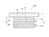
図3を用いて、圧電シートにおける焦電効果に起因する出力をキャンセルするメカニズムを説明する。図3は、圧力検出器の断面図である。 A mechanism for canceling the output due to the pyroelectric effect in the piezoelectric sheet will be described with reference to FIG. FIG. 3 is a cross-sectional view of the pressure detector.
第1圧電シート3aと第2圧電シート3bが強誘電体から構成される場合、第1圧電シート3aと第2圧電シート3bは、無押庄状態での分極方向が互いに逆方向になるよう構成されていることが好ましい。上記のように構成されていると、圧力検出器100内で温度変化が生じて、圧電シート3内に焦電効果が発生した場合に、図3に示すように、第1圧電シート3aの入力面側と第2圧電シート3bの背面側で正負同じ電荷が生じる。
第1圧電シート3aと第2圧電シート3bは、厚みが十分薄く(例えば、5μm〜50μm)、かつ、同じ特性を有する材料から構成すると、第1圧電シート3aの背面側の面と第2圧電シート3bの入力面側の面との間で、電位同士がほぼ等しくなり、その結果、第1圧電シート3aの入力面側の面と第2圧電シート3bの背面側の面との間で、電位同士が等しくなることが導き出される。
When the 1st
When the first
したがって、上記のように構成すると、圧電シート3が焦電効果の影響を受けた場合、焦電効果に起因して発生する第1圧電シート3aの入力面側の面の電位と第2圧電シート3bの背面側の面の電位はほぼ等しくなる。すると、圧力検出器100において、第1圧電シート3aと第2圧電シート3bが焦電効果の影響を受けた場合に、検出電極4によって検出される圧電シート3として焦電効果に起因する電位差は、ほぼ「0」となる。したがって、第1圧電シート3aと第2圧電シート3bに焦電効果が発生しても、圧電シート3全体としては焦電効果に起因する電位差がほとんど検出されない。すなわち、圧電シート3(第1圧電シート3aと第2圧電シート3b)が、強誘電体から構成される場合、圧電シート3と検出電極4が上記のように構成されることにより、温度変化に伴う誤動作(特に、焦電効果に起因した誤動作)がほとんど生じない。
Therefore, when configured as described above, when the
(8)中間接着層
前述したように、第1圧電シート3a及び第2圧電シート3bの間には、中間接着層8が配置されている。中間接着層8には、例えばPSAが用いられる。
(8) Intermediate adhesive layer As described above, the intermediate
中間接着層8は、従来に比べて軟らかい材料からなり、弾性係数が10MPa未満である。中間接着層8の弾性係数は、好ましくは、1MPa以下である。さらに具体的には、中間接着層8の弾性係数は、0.05MPa〜1MPaの範囲が好ましく、より好ましくは0.1MPa〜0.3MPaの範囲である。以上より、この実施形態では、中間接着層8は、第1圧電シート3a及び第2圧電シート3bの間で、比較的弾性係数が低い弾性体として機能している。
中間接着層8は、上記の弾性係数を実現すればよく、材料の種類は特に限定されない。ただし、中間接着層8は、例えば、アクリル系粘着剤やシリコーン系粘着剤からなる。いずれの粘着剤も、分子量を小さく架橋密度が小さいため、弾性係数が小さいからである。
The intermediate
The intermediate
中間接着層8の厚みは、5μm以上である。より好ましくは、中間接着層8の厚みは、25〜100μmの範囲である。
The thickness of the intermediate
図4を用いて、圧力検出器100に押圧を加えた場合の電荷発生メカニズムを説明する。図4は、圧力検出器の断面図である。
図4に示すように、圧力検出器100に押圧を加えたとき、支持基板1は圧電シート3や検出電極4に比べて高い剛性を有しているため、圧電シート3(第1圧電シート3aと第2圧電シート3b)には引張応力が生じる。このとき、第1圧電シート3aには引張応力σuが生じ、第2圧電シート3bには引張応力σlが生じる。その結果、第1圧電シート3aと第2圧電シート3bの入力面側の面と背面側の面には、上記引張応力に応じた電荷がそれぞれ発生する。そして、発生した電荷によって、第1圧電シート3a及び第2圧電シート3bのそれぞれの入力面側と背面側の面との間には電位差が発生する。第1圧電シート3aの間で発生する電位差V1’は、第1圧電シート3a入力面側の電位と背面側の電位との差であり、電位差V1’は引張応力σuの大きさに比例している。第2圧電シート3bの間で発生する電位差V2’は、第2圧電シート3bの入力面側の電位と背面側の電位との差であり、電位差V2’は引張応力σlの大きさに比例している。
The charge generation mechanism when pressure is applied to the
As shown in FIG. 4, when the
この実施形態では、引張応力σlが引張応力σuより小さくなっており、それにより電位差V2の絶対値が電位差V1の絶対値より小さくなっている。したがって、圧力検出器100の検出感度が高くなっている。このような効果が得られたのは、上記の特性を有する中間接着層8を新たに設けたからである。
In this embodiment, the tensile stress σ l is smaller than the tensile stress σ u , so that the absolute value of the potential difference V 2 is smaller than the absolute value of the potential difference V 1 . Therefore, the detection sensitivity of the
上記の構成に加え、中間接着層8の厚みが5μmを超えている場合は、前記の効果がさらに高くなる。なお、中間接着層8の厚みは25μm程度あることが好ましい。
上記の構成に加え、接着層2の弾性係数が中間接着層8の弾性係数の10倍以上である場合は、前記の効果がさらに高くなる。具体的には、接着層2の弾性係数は10MPa以上であり、1GPa程度あることが好ましい。この場合、接着層2の弾性係数が、中間接着層の弾性係数の10倍以上であることが好ましい。
In addition to the above configuration, when the thickness of the intermediate
In addition to the above configuration, when the elastic modulus of the
前記第1実施形態では、第1圧電シート3a及び第2圧電シート3bの間に配置されていたのは中間接着層8だけであった。しかし、上記の特性を満たす弾性体であれば接着層のみの構成には限定されない。例えば、弾性体はコアシート及び両面の接着剤から構成されていてもよい。また、弾性体の一部に光学的特性を実現するシートが用いられてもよい。
In the first embodiment, only the intermediate
以下に第1実施形態の原理と効果を示すためにおこなったシミュレーション結果を説明する。シミュレーションは、上記実施形態と同様の構造であり、ガラス(支持基板1に相当)にバイモルフ(圧電シート3に相当)を貼合わせ、四辺を土台(電子機器110の筐体6に相当)に両面テープで固定した圧力検出器(圧力検出器100に相当)を想定した。この圧力検出器において、ガラスの中央部に1Nの力を加えるという条件を採用した。圧電シートは、フィルム状のPVDFの共重合体を想定した。ガラスサイズは、例えば、120mm×60mmであり、厚みは例えば0.55mmである。シミュレーションには、FEMシミュレーションソフトを用いた。
The simulation results performed to show the principle and effect of the first embodiment will be described below. The simulation has the same structure as that of the above embodiment, and a bimorph (corresponding to the piezoelectric sheet 3) is pasted on glass (corresponding to the support substrate 1), and the four sides are both surfaces on the base (corresponding to the
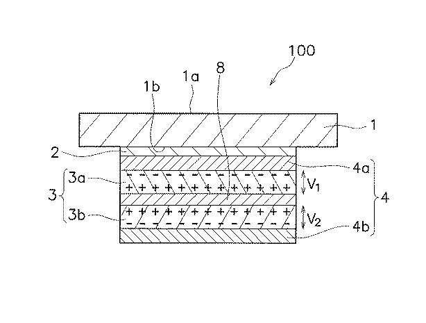
表1において、2枚の圧電シート(第1圧電シート3a及び第2圧電シート3bに相当)を弾性体(中間接着層8に相当)によって接着してなるバイモルフを、接着剤(接着層2に相当)でガラスに貼り合せた場合のシミュレーション結果である。X方向とY方向はそれぞれ上面図の長辺方向と短辺方向であり、上側の第1圧電シート(PIEZO U)と下側の第2圧電シート(PIEZO L)からなる圧電シートに加わる応力をXとY方向について算出した。
In Table 1, a bimorph formed by bonding two piezoelectric sheets (corresponding to the first
シミュレーションNo.A3、A4、A5、A6、A7、A10、A11、A12、A13、A14が本実施形態の最低限の条件を満たした実施例であり、シミュレーションNo.A1、A2、A8、A9が本実施形態の最低限の条件を満たしていない参考例である。なお、A1〜A7はガラスと圧電シートとの間の弾性体の弾性係数を低くした場合(10MPa)であり、A8〜A14はと、ガラスと圧電シートとの間の弾性体の弾性係数を高くした場合(1GPa)である。 Simulation No. A3, A4, A5, A6, A7, A10, A11, A12, A13, and A14 are examples that satisfy the minimum conditions of this embodiment. A1, A2, A8, and A9 are reference examples that do not satisfy the minimum conditions of this embodiment. A1 to A7 are cases where the elastic coefficient of the elastic body between the glass and the piezoelectric sheet is low (10 MPa), and A8 to A14 are high and the elastic coefficient of the elastic body between the glass and the piezoelectric sheet is high. (1 GPa).
参考例A1のように弾性体が存在しない場合、つまり極薄くて非常に硬い接着剤で貼合せている場合は、第2圧電シートで発生する引張応力が第1圧電シートで発生する引張応力より大きくなっており、しかもその差(σux−σlx、σuy−σly)はあまり大きくない。逆に、実施例A4のように、軟らかい弾性体を介している(弾性係数1MPa)場合は、弾性体が存在しない場合と逆に、第2圧電シートで発生する引張応力が第1圧電シートで発生する引張応力より小さくなっており、しかもその差(σux−σlx、σuy−σly)が参考例A1より大きくなっている。
When the elastic body does not exist as in Reference Example A1, that is, when bonded with an extremely thin and very hard adhesive, the tensile stress generated in the second piezoelectric sheet is greater than the tensile stress generated in the first piezoelectric sheet. Further, the difference (σux−σlx, σuy−σly) is not so large. On the contrary, when the elastic body is interposed (
さらに弾性体を軟らかくする又は厚くすると、第2圧電シートで発生する引張応力と第1圧電シートで発生する引張応力の差(σux−σlx、σuy−σly)が大きくなっていく。実施例A4をより弾性係数を小さくした例が実施例A5、A6、A7である。実施例A5と弾性係数は同じであるが厚みを大きくした例が実施例A6である。いずれの場合もより好ましい結果が得られている。
実施例A3と実施例A4は弾性体の弾性係数は同じであるが、実施例A4の厚みが大きくなっている。その結果、実施例A4において発生する引張応力の差は実施例A3に比べて大きくなっている。実施例A5と実施例A6との関係、実施例A10と実施例A11との関係、実施例A12と実施例A13との関係も同様である。
以上のように、圧電シート間に弾性体を形成し、より軟らかく、又はより厚くすることで圧力検出器の押圧検出感度を上げられることが分かる。
When the elastic body is further softened or thickened, the difference (σux−σlx, σuy−σly) between the tensile stress generated in the second piezoelectric sheet and the tensile stress generated in the first piezoelectric sheet increases. Examples in which the elastic modulus of the example A4 is further reduced are examples A5, A6, and A7. Example A6 is an example in which the elastic modulus is the same as Example A5 but the thickness is increased. In either case, more preferable results are obtained.
Example A3 and Example A4 have the same elastic modulus, but the thickness of Example A4 is larger. As a result, the difference in tensile stress generated in Example A4 is larger than that in Example A3. The relationship between Example A5 and Example A6, the relationship between Example A10 and Example A11, and the relationship between Example A12 and Example A13 are the same.
As described above, it is understood that the pressure detection sensitivity of the pressure detector can be increased by forming an elastic body between the piezoelectric sheets and making it softer or thicker.
実施例A3〜A7(ガラスと圧電シートとの間の接着層が軟らかい)と実施例A10〜A14(ガラスと圧電シートとの間の接着層が硬い)とをそれぞれ比較すると、後者の方がより大きな引張応力の差が得られていることが分かる。このことより、ガラスとバイモルフを接着している接着剤を硬くすると、第2圧電シートで発生する引張応力が第1圧電シートで発生する引張応力よりさらに小さくなり、圧力検出器の押圧検出感度を上げられることが分かる。 When Examples A3 to A7 (the adhesive layer between the glass and the piezoelectric sheet is soft) and Examples A10 to A14 (the adhesive layer between the glass and the piezoelectric sheet are hard) are compared, the latter is more It can be seen that a large difference in tensile stress is obtained. From this fact, when the adhesive that bonds the glass and bimorph is hardened, the tensile stress generated in the second piezoelectric sheet becomes smaller than the tensile stress generated in the first piezoelectric sheet, and the pressure detection sensitivity of the pressure detector is increased. You can see that
2.第2実施形態
図5を用いて、第2実施形態の圧力検出器100Aを説明する。
圧力検出器100Aの基本的な構造は、第1実施形態の圧力検出器100と同じである。したがって、ここでは異なる点のみを説明する。
2. Second Embodiment
The basic structure of the
圧力検出器100Aは、第1実施形態の構造に加えて、ディスプレイ装置5(第2シート部材の一例)を有している。ディスプレイ装置5は、接着層9を介して、第2検出電極4bの背面側に固定されている。なお、ディスプレイ装置5はLCDや有機ELから構成されている。ディスプレイ装置5は、圧電シート3に比べて剛性が高い。
このようにして、圧力検出器100Aは、入力面側から背面側に向かって、支持基板1、接着層2、第1検出電極4a、第1圧電シート3a、中間接着層8、第2圧電シート3b、第2検出電極4b、接着層9、ディスプレイ装置5を有している。
The
In this way, the
この実施形態でも、中間接着層8の弾性係数を低くすることで、引張応力σlが引張応力σuより小さくなっており、それにより電位差V1が電位差V2より大きくなっている。したがって、圧力検出器100Bの検出感度が高くなっている。
また、ディスプレイ装置5を圧電シート3の背面側に設けることによって、第1実施形態に比べて、第2圧電シートで発生する引張応力が第1圧電シートで発生する引張応力よりさらに小さくなっており、圧力検出器の押圧検出感度を上げられる。
Also in this embodiment, the tensile stress σ l is smaller than the tensile stress σ u by lowering the elastic modulus of the intermediate
Further, by providing the
また、この条件で弾性体をさらに柔らかく又は厚みを大きくすると、第2圧電シート3bで発生する引張応力がマイナスになる(つまり、圧縮応力が発生する)。この結果、圧力検出器の押圧検出感度をさらに上げられる。
また、ディスプレイ装置5を設けることで、圧力検出器100Aの曲げ剛性も向上している。つまり、押圧を加えてもたわみの少ない圧力検出器となる。
なお、ディスプレイ装置の代わりにガラスのような硬い材料を別に設けても同じ効果がある。ただし、いずれの場合も圧力検出器の最下面に貼られる部材の弾性係数は10GPa以上であることが好ましい。
Also, if the elastic body is further softened or thickened under these conditions, the tensile stress generated in the second
Further, by providing the
Note that the same effect can be obtained by providing a separate hard material such as glass instead of the display device. However, in any case, it is preferable that the elastic coefficient of the member attached to the lowermost surface of the pressure detector is 10 GPa or more.
以下に第2実施形態の原理と効果を示すためにおこなったシミュレーション結果を説明する。 The simulation results performed to show the principle and effect of the second embodiment will be described below.
シミュレーションNo.B3〜B7が本実施形態の最低限の条件を満たした実施例であり、シミュレーションNo.B1〜B2が本実施形態の最低限の条件を満たしていない参考例である。
実施例B3〜B7と、弾性体の弾性係数及び厚みの条件が同じである第1実施形態の実施例A3〜A7とを比較すると、実施例B3〜B7の方が、実施例A3〜A7に比べて、発生する引張応力同士の差はそれぞれ大きくなっている。以上より、剛性が高いシートを圧電シートの背面側に固定すると、圧力検出器の検出感度をさらに高められることが分かる。
Simulation No. B3 to B7 are examples that satisfy the minimum conditions of this embodiment. B1 to B2 are reference examples that do not satisfy the minimum conditions of this embodiment.
When Examples B3 to B7 are compared with Examples A3 to A7 of the first embodiment in which the elastic modulus and thickness conditions of the elastic body are the same, Examples B3 to B7 are different from Examples A3 to A7. In comparison, the difference between the generated tensile stresses is larger. From the above, it can be seen that the detection sensitivity of the pressure detector can be further enhanced by fixing a highly rigid sheet to the back side of the piezoelectric sheet.
3.第3実施形態
図6を用いて、第3実施形態としての圧力検出器100Bを説明する。図6は、圧力検出器の断面図である。
圧力検出器100Bは、第1実施形態と基本構造が同じである。したがって、ここでは、異なる点のみを説明する。
3. Third Embodiment
The
この実施形態では、検出電極は、蒸着やスクリーン印刷などを用いて樹脂フィルムの表面に形成されている。具体的には、第1検出電極4aは、樹脂フィルム11の背面に形成されている。樹脂フィルム11は、接着層12を介して圧電シート3に固定されている。また、樹脂フィルム11は、接着層2を介して支持基板1に固定されている。第2検出電極4bは、樹脂フィルム13の入力側面に形成されている。樹脂フィルム13は、接着層14を介して圧電シート3の背面に固定されている。
In this embodiment, the detection electrode is formed on the surface of the resin film using vapor deposition or screen printing. Specifically, the
このようにして、圧力検出器100Bは、入力面側から背面側に向かって、支持基板1、接着層2、樹脂フィルム11(第1検出電極4aを含む)、接着層12、第1圧電シート3a、中間接着層8、第2圧電シート3b、接着層14、樹脂フィルム13(第2検出電極4bを含む)を有している。
この実施形態でも、中間接着層8の弾性係数を低くすることで、引張応力σlが引張応力σuより小さくなっており、それにより電位差V1が電位差V2より大きくなっている。したがって、圧力検出器100Bの検出感度が高くなっている。
さらに、中間接着層8の厚みを増加することで、さらに上記の効果を高めることができる。
In this manner, the
Also in this embodiment, the tensile stress σ l is smaller than the tensile stress σ u by lowering the elastic modulus of the intermediate
Furthermore, the above effect can be further enhanced by increasing the thickness of the intermediate
さらに、中間接着層8以外の接着層である接着層2、接着層12、及び接着層14の弾性係数が中間接着層8の弾性係数の10倍以上である場合は、前記の効果がさらに高くなる。具体的には、これら接着層の弾性係数は10MPa以上であり、1GPa程度あることが好ましい。
Furthermore, when the elastic modulus of the
以下に第3実施形態の原理と効果を示すために行ったシミュレーション結果を説明する。 The simulation results performed to show the principle and effect of the third embodiment will be described below.
シミュレーションNo.C3〜C7及びC10〜C14が本実施形態の最低限の条件を満たした実施例であり、シミュレーションNo.C1〜C2及びC8〜C9が本実施形態の最低限の条件を満たしていない参考例である。 Simulation No. C3 to C7 and C10 to C14 are examples in which the minimum conditions of this embodiment are satisfied. C1-C2 and C8-C9 are reference examples that do not satisfy the minimum conditions of this embodiment.
実施例C3〜C7(ガラスと圧電シートとの間の接着層、及び各樹脂フィルムと圧電シートとの間の接着層が軟らかい)と実施例C10〜C14(ガラスと圧電シートとの間の接着層、及び各樹脂フィルムと圧電シートとの間の接着層が硬い)とをそれぞれ比較すると、後者の方がより大きな引張応力の差が得られていることが分かる。このことより、弾性体以外の接着剤の弾性係数を高くすると、第2圧電シートで発生する引張応力と第1圧電シートで発生する引張応力との差がさらに大きく、それにより圧力検出器の押圧検出感度を上げられることが分かる。 Examples C3 to C7 (adhesive layer between glass and piezoelectric sheet, and adhesive layer between each resin film and piezoelectric sheet are soft) and Examples C10 to C14 (adhesive layer between glass and piezoelectric sheet) And the adhesive layer between each resin film and the piezoelectric sheet are harder), it can be seen that a greater difference in tensile stress is obtained in the latter. Accordingly, when the elastic modulus of the adhesive other than the elastic body is increased, the difference between the tensile stress generated in the second piezoelectric sheet and the tensile stress generated in the first piezoelectric sheet is further increased, thereby pressing the pressure detector. It can be seen that the detection sensitivity can be increased.
次に、表4を用いて、実際に試作した圧力検出器の出力を測定した結果を以下に示す。圧力検出器の層構成は第3実施形態と同じである。バイモルフ(圧電シート3に相当)の圧電シート(第1圧電シート3a、第2圧電シート3bに相当)同士の間に軟らかい接着層であるPSAmid(中間接着層8に相当)を設けた。また、バイモルフ(圧電シート3に相当)をITOフィルム(樹脂フィルム11、樹脂フィルム13に相当)で両側から挟んでさらに、ガラス(支持基板1に相当)にPSA1(接着層2に相当)を介して貼り付けた構造の圧力検出器(圧力検出器100bに相当)を試作した。ITOフィルムは、PSA2(接着層12に相当)及びPSA3(接着層14に相当)を介してバイモルフに貼り付けられた。そして、押圧を加えて出てくる電力を電荷として、チャージアンプ(図示せず)で検出した。
Next, using Table 4, the result of measuring the output of the actually manufactured pressure detector is shown below. The layer structure of the pressure detector is the same as in the third embodiment. PSAmid (corresponding to the intermediate adhesive layer 8), which is a soft adhesive layer, was provided between the bimorph (corresponding to the piezoelectric sheet 3) piezoelectric sheets (corresponding to the first
実施例としてのセンサ2では、PSA1,PSA2及びPSA3に薄くて硬いものを採用したが、PSAmid(中間接着層8に相当)に軟らかい通常のPSAを採用した。PSAmidにおける通常のPSAの弾性係数は、約0.1MPaであった。センサ1とは逆の符号の電荷が検出され、その量はセンサ1の三倍の1.55nCであり、効果が見られた。
In the
4.第4実施形態
第1〜第3実施形態では、圧力検出器のバイモルフは支持基板1に固定されていたが、本発明はそれら実施形態に限定されない。圧力検出器のバイモルフはタッチパネルの背面に固定されてもよい。その場合、押圧力だけでなく、押圧の位置も検出できる。
タッチパネルとしては、静電容量方式、抵抗膜方式、光学方式が挙げられる。以下に、静電容量方式の場合について説明する。
4). Fourth Embodiment In the first to third embodiments, the bimorph of the pressure detector is fixed to the
Examples of the touch panel include a capacitance method, a resistance film method, and an optical method. The case of the electrostatic capacity method will be described below.
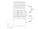
以下、図7及び図8を用いて、タッチパネル110Cを説明する。図7は、タッチパネルの断面図である。図8は、電極の展開図である。
タッチパネル110Cに含まれる圧力検出器100Cの基本的な構造は、第1〜第3実施形態と同様である。したがって、共通部分の説明を省略する。ただし、圧力検出器100Cは、第2実施形態のようにディスプレイ装置5を最背面側に有している。また、圧力検出器100は、第3実施形態のように第1検出電極4a及び第2検出電極4bがそれぞれ樹脂フィルム11及び樹脂フィルム13に形成されている。
Hereinafter, the
The basic structure of the pressure detector 100C included in the
図7及び図8に示すように、タッチパネル110Cは、圧力検出器100Cに加えて、タッチセンサ51を有している。タッチセンサ51は、主に、上部電極53と、下部電極55とを有している。
As shown in FIGS. 7 and 8, the
上部電極53は、樹脂フィルム11の入力側面に複数形成されている。複数の上部電極53は、Y軸方向に所定間隔を隔てて並ぶように互いに平行に配置されている。本実施形態では、上部電極53は、ストライプ状(一定幅を有する直線状)に形成されている。なお、上部電極53は、例えば波状やジグザグ状に形成されてもよい。いずれにしても、上部電極53のそれぞれは、全体として、X軸方向に沿って延在するように形成されている。
A plurality of
また、上部電極53は、透明性に優れた材料を用いて構成されていることが好ましい。このような要求を満足する材料としては、例えば酸化スズ、酸化インジウム、酸化アンチモン、酸化亜鉛、酸化カドミウム、及びITO(Indium Tin Oxide)等の金属酸化物、銀ナノワイヤ一、カーボンナノチューブ、導電性ポリマ一等が例示される。上部電極53はこれらの材料を用いて構成された透明導電膜であり、その厚みは、例えば5nm〜5000nmとすることができる。本実施形態では、ITO薄膜により上部電極53が構成されている。この場合、上部電極53は、蒸着やスクリーン印刷などを用いて樹脂フィルム11の入力側面に形成されて、支持基板1に接着層2で固着されている。なお、上部電極は、蒸着やスクリーン印刷などを用いて支持基板1の背面に直接形成されてもよい。なお、上部電極53の厚みは、例えば、lnm〜20μmである。
Moreover, it is preferable that the
下部電極55は、本実施形態では、上部電極53の背面側に複数形成されている。複数の下部電極55は、X軸方向に所定間隔を隔てて並ぶように互いに平行に配置されている。本実施形態では、下部電極55は、ストライプ状(一定幅を有する直線状)に形成されている。なお、下部電極55は、例えば波状やジグザグ状に形成されてもよい。いずれにしても、下部電極55のそれぞれは、全体として、Y軸方向に沿って延在するように形成されている。これにより、上部電極53と下部電極55とは、平面視で互いに交差(本例では直交)するように配置されている。下部電極55は、上部電極53と同様、透明性に優れた材料を用いて構成されていることが好ましい。下部電極55を構成する材料や厚みに関しては、上部電極53と同様である。また、下部電極55の形成方法に関しても、上部電極53と同様である。
この実施形態では、下部電極55は、蒸着やスクリーン印刷などを用いて樹脂フィルム13の表面に形成されて、第1圧電シート3aに接着層12を介して固着されている。
なお、上部電極53及び下部電極55は、検出電極と同様に、銀、銅などの導電性の金属からなるメッシュ構造であってもよい。
In the present embodiment, a plurality of
In this embodiment, the
The
複数の上部電極53は、それぞれ引き回し配線を介して、検出回路(図示せず)に接続されている。また、複数の下部電極55も、それぞれ引き回し配線を介して、検出回路に接続されている。なお、引き回し配線は、金、銀、銅、及びニッケル等の金属、又はカーボン等の導電ベーストを用いて構成される。
Each of the plurality of
この実施形態では、下部電極55は、圧力検出器100Cの第1検出電極4aと兼用されている。そのため、両電極を絶縁するための別の層が不要になり、したがって、装置が軽量化及び薄型化される。また、電極材料が低減される。
In this embodiment, the
タッチパネル110Cには、CPU等の演算処理装置を含む制御部(図示せず)が備えられており、この制御部が位置検出演算及び押圧力検出演算を行うように構成されている。具体的には、タッチパネル110C(入力面1a)に対してユーザの指等がタッチされると上部電極53とユーザの指等との問の静電容量や下部電極55とユーザの指等との間の静電容量が変化する。制御部は、検出器から得られた静電容量の変化に基づいて、入力面1aにおけるX−Y座標系での押圧位置を決定することができる。また、タッチパネル110Cに対してユーザの指等がタッチされると、上述したように圧電シート3間における電位差は、加えられた押圧力の大きさに応じて変化する。制御部は、圧電シート3の電位差変化を検出することにより、入力面1aと直交する方向(Z方向)に加えられた押圧力の大きさを決定できる。
The
なお、圧力検出器とタッチパネルを組み合わせ使う場合に、電極の共通化は必ずしもしなくてよい。
また、上記の装置の層構成は一実施形態であって、本発明はこれに限定されない。
In addition, when using a pressure detector and a touch panel in combination, it is not always necessary to share the electrodes.
Further, the layer configuration of the above-described device is one embodiment, and the present invention is not limited to this.
5.実施形態の共通事項
上記第1〜第5実施形態は、下記の構成及び機能を共通に有している。
圧力検出装置(例えば、圧力検出器100、100A、100B、100C)は、外部から加えられた圧力によって発生する2枚の圧電シート間の電位差に基づいて圧力を検出するための圧力検出装置である。圧力検出装置は、シート部材と、第1圧電シートと、第2圧電シートと、第1検出電極と、第2検出電極と、弾性体と、を備えている。
シート部材(例えば、支持基板1、タッチパネル)は、圧力が作用する第1面(例えば、入力面1a)と、縁部が支持される第2面(例えば、背面1b)を有する。
第1圧電シート(例えば、第1圧電シート3a)は、シート部材の第2面の中央部に配置されている。
第2圧電シート(例えば、第2圧電シート3b)は、第1圧電シートのシート部材と反対側において、第1圧電シートに対向して配置されている。
第1検出電極(例えば、第1検出電極4a)は、第1圧電シートの第2圧電シートと反対側に配置されている。
第2検出電極(例えば、第2検出電極4b)は、第2圧電シートの第1圧電シートの反対側に配置されている。
弾性体(例えば、中間接着層8)は、第1圧電シートと第2圧電シートとの間に配置されている。弾性体は、弾性係数が10MPa未満である。
5. Common Items of Embodiments The first to fifth embodiments have the following configurations and functions in common.
The pressure detection devices (for example,
The sheet member (for example,
The first piezoelectric sheet (for example, the first
The second piezoelectric sheet (for example, the second
The first detection electrode (for example, the
The second detection electrode (for example, the
The elastic body (for example, the intermediate adhesive layer 8) is disposed between the first piezoelectric sheet and the second piezoelectric sheet. The elastic body has an elastic modulus of less than 10 MPa.
この装置では、シート部材の第1面の中央部が押されると、シート部材は縁部が支持部に支持されながらたわむ(図4参照)。その結果、第1圧電シート及び第2圧電シートもたわむ。このときに、第1圧電シートと第2圧電シートとの間に配置された弾性体の弾性係数が10MPa未満であるので、第2圧電シートの引張応力(例えば、σl)が第1圧電シートの引張応力(例えば、σu)より小さくなる。これにより、第1検出電極で発生する電荷量が第2検出電極で発生する電荷量より大きくなり、第1検出電極及び第2検出電極の間の電位差が充分に大きくなる。この結果、圧力検出装置の押圧検出感度が高くなる。 In this apparatus, when the central portion of the first surface of the sheet member is pressed, the sheet member bends while the edge portion is supported by the support portion (see FIG. 4). As a result, the first piezoelectric sheet and the second piezoelectric sheet are also bent. At this time, since the elastic coefficient of the elastic body disposed between the first piezoelectric sheet and the second piezoelectric sheet is less than 10 MPa, the tensile stress (for example, σ l ) of the second piezoelectric sheet is the first piezoelectric sheet. Less than the tensile stress (for example, σ u ). As a result, the amount of charge generated at the first detection electrode becomes larger than the amount of charge generated at the second detection electrode, and the potential difference between the first detection electrode and the second detection electrode becomes sufficiently large. As a result, the pressure detection sensitivity of the pressure detection device is increased.
6.他の実施形態
以上、本発明の複数の一実施形態について説明したが、本発明は上記実施形態に限定されるものではなく、発明の要旨を逸脱しない範囲で種々の変更が可能である。特に、本明細書に書かれた複数の実施形態及び変形例は必要に応じて任意に組み合せ可能である。
6). Other Embodiments Although a plurality of embodiments of the present invention have been described above, the present invention is not limited to the above-described embodiments, and various modifications can be made without departing from the scope of the invention. In particular, a plurality of embodiments and modifications described in this specification can be arbitrarily combined as necessary.
本発明は、圧力検出装置、特に、2枚の圧電シートを貼り合わせたバイモルフを用いた圧力検出装置に広く適用できる。 The present invention can be widely applied to a pressure detection device, particularly a pressure detection device using a bimorph obtained by bonding two piezoelectric sheets.
1 :支持基板
1a :入力面
2 :接着層
3 :圧電シート
3a :第1圧電シート
3b :第2圧電シート
4 :検出電極
4a :第1検出電極
4b :第2検出電極
5 :ディスプレイ装置
6 :筐体
6a :凹部
6b :支持部
7 :空間
8 :中間接着層
9 :接着層
11 :樹脂フィルム
12 :接着層
13 :樹脂フィルム
14 :接着層
100 :圧力検出器
100A :圧力検出器
100B :圧力検出器
110 :電子機器
110C :タッチパネル
σu :引張応力
σl :引張応力
V1 :電位差
V2 :電位差
1:
Claims (7)
前記圧力が作用する第1面と、縁部が支持される第2面とを有するシート部材と、
前記シート部材の第2面の中央部に配置された第1圧電シートと、
前記第1圧電シートの前記シート部材と反対側において、前記第1圧電シートに対向して配置された第2圧電シートと、
前記第1圧電シートの前記第2圧電シートと反対側に配置された第1検出電極と、
前記第2圧電シートの前記第1圧電シートの反対側に配置された第2検出電極と、
前記第1圧電シートと前記第2圧電シートとの間に配置された、弾性係数が10MPa未満の弾性体と、
を備えた圧力検出装置。 A pressure detection device for detecting the pressure based on a potential difference between two piezoelectric sheets generated by pressure applied from the outside,
A sheet member having a first surface on which the pressure acts and a second surface on which an edge is supported;
A first piezoelectric sheet disposed in the center of the second surface of the sheet member;
A second piezoelectric sheet disposed opposite to the first piezoelectric sheet on a side opposite to the sheet member of the first piezoelectric sheet;
A first detection electrode disposed on the opposite side of the first piezoelectric sheet from the second piezoelectric sheet;
A second detection electrode disposed on the opposite side of the first piezoelectric sheet to the second piezoelectric sheet;
An elastic body having an elastic coefficient of less than 10 MPa, disposed between the first piezoelectric sheet and the second piezoelectric sheet;
A pressure detection device.
Priority Applications (3)
| Application Number | Priority Date | Filing Date | Title |
|---|---|---|---|
| JP2014068451A JP2015190863A (en) | 2014-03-28 | 2014-03-28 | Pressure detector |
| PCT/JP2015/054212 WO2015146367A1 (en) | 2014-03-28 | 2015-02-17 | Pressure detection apparatus |
| TW104109292A TW201543015A (en) | 2014-03-28 | 2015-03-24 | Pressure detection apparatus |
Applications Claiming Priority (1)
| Application Number | Priority Date | Filing Date | Title |
|---|---|---|---|
| JP2014068451A JP2015190863A (en) | 2014-03-28 | 2014-03-28 | Pressure detector |
Publications (1)
| Publication Number | Publication Date |
|---|---|
| JP2015190863A true JP2015190863A (en) | 2015-11-02 |
Family
ID=54194903
Family Applications (1)
| Application Number | Title | Priority Date | Filing Date |
|---|---|---|---|
| JP2014068451A Pending JP2015190863A (en) | 2014-03-28 | 2014-03-28 | Pressure detector |
Country Status (3)
| Country | Link |
|---|---|
| JP (1) | JP2015190863A (en) |
| TW (1) | TW201543015A (en) |
| WO (1) | WO2015146367A1 (en) |
Cited By (10)
| Publication number | Priority date | Publication date | Assignee | Title |
|---|---|---|---|---|
| KR20160032263A (en) * | 2013-12-18 | 2016-03-23 | 니폰샤신인사츠가부시키가이샤 | Pressure detector and touch panel provided with pressure detector |
| WO2017170616A1 (en) * | 2016-03-28 | 2017-10-05 | ダイキン工業株式会社 | Bimorph-type piezoelectric film |
| JP2019128315A (en) * | 2018-01-26 | 2019-08-01 | シャープ株式会社 | Pressure detector and display device |
| JP2019138741A (en) * | 2018-02-08 | 2019-08-22 | 国立研究開発法人産業技術総合研究所 | Pressure sensor |
| WO2020129346A1 (en) * | 2018-12-20 | 2020-06-25 | 株式会社村田製作所 | Pressure sensor and pressure detection device |
| WO2020255920A1 (en) * | 2019-06-19 | 2020-12-24 | 三井化学株式会社 | Tactile sensor formed on polyimide thin film having high total light transmittance, and switching device using same |
| JP2022114656A (en) * | 2021-01-27 | 2022-08-08 | サクサ株式会社 | Pressure sensor and position detection device |
| JP2022129762A (en) * | 2021-02-25 | 2022-09-06 | サクサ株式会社 | Piezoelectric sensor and position detection device |
| JPWO2023153427A1 (en) * | 2022-02-10 | 2023-08-17 | ||
| JPWO2023153426A1 (en) * | 2022-02-10 | 2023-08-17 |
Families Citing this family (9)
| Publication number | Priority date | Publication date | Assignee | Title |
|---|---|---|---|---|
| JP6652882B2 (en) * | 2016-04-28 | 2020-02-26 | Nissha株式会社 | Pressure detector |
| KR102564349B1 (en) | 2016-09-30 | 2023-08-04 | 엘지디스플레이 주식회사 | Organic light emitting display apparatus |
| CN106903037A (en) * | 2017-01-23 | 2017-06-30 | 中国科学院苏州生物医学工程技术研究所 | Ultrasonic transducer, ultrasonic array probe and ultrasonic image-forming system |
| WO2019111775A1 (en) * | 2017-12-07 | 2019-06-13 | ソニー株式会社 | Display panel and display device |
| TWI752272B (en) * | 2018-10-15 | 2022-01-11 | 鴻勁精密股份有限公司 | Pressure detection unit and operating equipment for its application |
| WO2020179376A1 (en) * | 2019-03-06 | 2020-09-10 | 日東電工株式会社 | Sensor device |
| CN113299188B (en) * | 2021-05-08 | 2022-04-26 | 武汉华星光电技术有限公司 | Display panel and manufacturing method thereof |
| WO2023153430A1 (en) * | 2022-02-10 | 2023-08-17 | 株式会社村田製作所 | Sensor |
| TWI907852B (en) * | 2023-04-25 | 2025-12-11 | 仁寶電腦工業股份有限公司 | Electronic device |
Family Cites Families (6)
| Publication number | Priority date | Publication date | Assignee | Title |
|---|---|---|---|---|
| JPH0663725B2 (en) * | 1985-12-27 | 1994-08-22 | ダイキン工業株式会社 | Piezoelectric sensor |
| JPH08236830A (en) * | 1995-03-01 | 1996-09-13 | Seiko Epson Corp | Electric-strain conversion device and piezoelectric sensor and piezoelectric actuator using the same |
| JP2001094392A (en) * | 1999-09-20 | 2001-04-06 | Toshiba Corp | Surface acoustic wave device and method of manufacturing the same |
| JP4236203B2 (en) * | 2005-11-15 | 2009-03-11 | 日本電信電話株式会社 | Acoustic element |
| JP5721126B2 (en) * | 2010-03-05 | 2015-05-20 | 国立研究開発法人産業技術総合研究所 | Piezoelectric sensor |
| JP5886029B2 (en) * | 2011-12-22 | 2016-03-16 | Kddi株式会社 | Telephone |
-
2014
- 2014-03-28 JP JP2014068451A patent/JP2015190863A/en active Pending
-
2015
- 2015-02-17 WO PCT/JP2015/054212 patent/WO2015146367A1/en not_active Ceased
- 2015-03-24 TW TW104109292A patent/TW201543015A/en unknown
Cited By (21)
| Publication number | Priority date | Publication date | Assignee | Title |
|---|---|---|---|---|
| KR20160032263A (en) * | 2013-12-18 | 2016-03-23 | 니폰샤신인사츠가부시키가이샤 | Pressure detector and touch panel provided with pressure detector |
| KR101673884B1 (en) | 2013-12-18 | 2016-11-08 | 니폰샤신인사츠가부시키가이샤 | Pressure detector and touch panel provided with pressure detector |
| WO2017170616A1 (en) * | 2016-03-28 | 2017-10-05 | ダイキン工業株式会社 | Bimorph-type piezoelectric film |
| JPWO2017170616A1 (en) * | 2016-03-28 | 2018-10-18 | ダイキン工業株式会社 | Bimorph type piezoelectric film |
| JP2019128315A (en) * | 2018-01-26 | 2019-08-01 | シャープ株式会社 | Pressure detector and display device |
| JP2019138741A (en) * | 2018-02-08 | 2019-08-22 | 国立研究開発法人産業技術総合研究所 | Pressure sensor |
| JP7128506B2 (en) | 2018-02-08 | 2022-08-31 | 国立研究開発法人産業技術総合研究所 | pressure sensor |
| WO2020129346A1 (en) * | 2018-12-20 | 2020-06-25 | 株式会社村田製作所 | Pressure sensor and pressure detection device |
| JP7064054B2 (en) | 2019-06-19 | 2022-05-09 | 三井化学株式会社 | A tactile sensor formed on a polyimide thin film with high total light transmittance and a switching device using it. |
| KR20210154233A (en) * | 2019-06-19 | 2021-12-20 | 미쓰이 가가쿠 가부시키가이샤 | A tactile sensor formed on a polyimide thin film having high total light transmittance and a switching device using the same |
| JPWO2020255920A1 (en) * | 2019-06-19 | 2020-12-24 | ||
| WO2020255920A1 (en) * | 2019-06-19 | 2020-12-24 | 三井化学株式会社 | Tactile sensor formed on polyimide thin film having high total light transmittance, and switching device using same |
| KR102551416B1 (en) | 2019-06-19 | 2023-07-04 | 미쓰이 가가쿠 가부시키가이샤 | A tactile sensor formed on a polyimide thin film having high total light transmittance and a switching device using the same |
| JP2022114656A (en) * | 2021-01-27 | 2022-08-08 | サクサ株式会社 | Pressure sensor and position detection device |
| JP7665990B2 (en) | 2021-01-27 | 2025-04-22 | サクサ株式会社 | Pressure sensor and position detection device |
| JP2022129762A (en) * | 2021-02-25 | 2022-09-06 | サクサ株式会社 | Piezoelectric sensor and position detection device |
| JP7666015B2 (en) | 2021-02-25 | 2025-04-22 | サクサ株式会社 | Piezoelectric sensor and position detection device |
| JPWO2023153427A1 (en) * | 2022-02-10 | 2023-08-17 | ||
| JPWO2023153426A1 (en) * | 2022-02-10 | 2023-08-17 | ||
| JP7609309B2 (en) | 2022-02-10 | 2025-01-07 | 株式会社村田製作所 | Electronics |
| US12339179B2 (en) | 2022-02-10 | 2025-06-24 | Murata Manufacturing Co., Ltd. | Electronic device |
Also Published As
| Publication number | Publication date |
|---|---|
| WO2015146367A1 (en) | 2015-10-01 |
| TW201543015A (en) | 2015-11-16 |
Similar Documents
| Publication | Publication Date | Title |
|---|---|---|
| WO2015146367A1 (en) | Pressure detection apparatus | |
| KR101673884B1 (en) | Pressure detector and touch panel provided with pressure detector | |
| JP5722954B2 (en) | Touch panel with pressure detection function | |
| CN106990862B (en) | Touch sensitive device, display device including the same, and method of manufacturing the display device | |
| US9665200B2 (en) | Temperature compensating transparent force sensor | |
| WO2015133251A1 (en) | Pressure sensitive sensor and touch panel | |
| JP6795097B2 (en) | Press sensor and electronic device | |
| CN105612481B (en) | Touch panel, touch input device and electronic device | |
| JP6104721B2 (en) | Piezoelectric sensor and pressure detection device | |
| CN105493010A (en) | Sensor device, display device, and input device | |
| JPWO2015041198A1 (en) | Press detection sensor | |
| CN106557246A (en) | A kind of three-dimensional input module | |
| WO2016059934A1 (en) | Pressure-detecting device | |
| JP6652882B2 (en) | Pressure detector | |
| CN109992099A (en) | Electronic equipment, touch display module and pressure-sensitive haptic feedback module | |
| TWI673636B (en) | Touch sensitive display and its touch module | |
| JP6418335B2 (en) | Touch panel, touch input device | |
| TW201812558A (en) | Force sensing architectures | |
| CN108170265B (en) | Touch-sensitive element and display device including the same | |
| WO2016103887A1 (en) | Pressure sensor | |
| TW202130195A (en) | Thin film component integreated piezoelectric element and the electronic device thereof | |
| TWM604089U (en) | Thin film component integrated with piezoelectric element and electronic device thereof |