JP2015192525A - Dc-dc converter and battery system - Google Patents
Dc-dc converter and battery system Download PDFInfo
- Publication number
- JP2015192525A JP2015192525A JP2014067997A JP2014067997A JP2015192525A JP 2015192525 A JP2015192525 A JP 2015192525A JP 2014067997 A JP2014067997 A JP 2014067997A JP 2014067997 A JP2014067997 A JP 2014067997A JP 2015192525 A JP2015192525 A JP 2015192525A
- Authority
- JP
- Japan
- Prior art keywords
- voltage value
- voltage
- diode
- switch element
- battery
- Prior art date
- Legal status (The legal status is an assumption and is not a legal conclusion. Google has not performed a legal analysis and makes no representation as to the accuracy of the status listed.)
- Granted
Links
Images
Classifications
-
- B—PERFORMING OPERATIONS; TRANSPORTING
- B60—VEHICLES IN GENERAL
- B60L—PROPULSION OF ELECTRICALLY-PROPELLED VEHICLES; SUPPLYING ELECTRIC POWER FOR AUXILIARY EQUIPMENT OF ELECTRICALLY-PROPELLED VEHICLES; ELECTRODYNAMIC BRAKE SYSTEMS FOR VEHICLES IN GENERAL; MAGNETIC SUSPENSION OR LEVITATION FOR VEHICLES; MONITORING OPERATING VARIABLES OF ELECTRICALLY-PROPELLED VEHICLES; ELECTRIC SAFETY DEVICES FOR ELECTRICALLY-PROPELLED VEHICLES
- B60L15/00—Methods, circuits, or devices for controlling the traction-motor speed of electrically-propelled vehicles
- B60L15/007—Physical arrangements or structures of drive train converters specially adapted for the propulsion motors of electric vehicles
-
- B—PERFORMING OPERATIONS; TRANSPORTING
- B60—VEHICLES IN GENERAL
- B60L—PROPULSION OF ELECTRICALLY-PROPELLED VEHICLES; SUPPLYING ELECTRIC POWER FOR AUXILIARY EQUIPMENT OF ELECTRICALLY-PROPELLED VEHICLES; ELECTRODYNAMIC BRAKE SYSTEMS FOR VEHICLES IN GENERAL; MAGNETIC SUSPENSION OR LEVITATION FOR VEHICLES; MONITORING OPERATING VARIABLES OF ELECTRICALLY-PROPELLED VEHICLES; ELECTRIC SAFETY DEVICES FOR ELECTRICALLY-PROPELLED VEHICLES
- B60L50/00—Electric propulsion with power supplied within the vehicle
- B60L50/50—Electric propulsion with power supplied within the vehicle using propulsion power supplied by batteries or fuel cells
- B60L50/51—Electric propulsion with power supplied within the vehicle using propulsion power supplied by batteries or fuel cells characterised by AC-motors
-
- B—PERFORMING OPERATIONS; TRANSPORTING
- B60—VEHICLES IN GENERAL
- B60L—PROPULSION OF ELECTRICALLY-PROPELLED VEHICLES; SUPPLYING ELECTRIC POWER FOR AUXILIARY EQUIPMENT OF ELECTRICALLY-PROPELLED VEHICLES; ELECTRODYNAMIC BRAKE SYSTEMS FOR VEHICLES IN GENERAL; MAGNETIC SUSPENSION OR LEVITATION FOR VEHICLES; MONITORING OPERATING VARIABLES OF ELECTRICALLY-PROPELLED VEHICLES; ELECTRIC SAFETY DEVICES FOR ELECTRICALLY-PROPELLED VEHICLES
- B60L58/00—Methods or circuit arrangements for monitoring or controlling batteries or fuel cells, specially adapted for electric vehicles
- B60L58/10—Methods or circuit arrangements for monitoring or controlling batteries or fuel cells, specially adapted for electric vehicles for monitoring or controlling batteries
- B60L58/12—Methods or circuit arrangements for monitoring or controlling batteries or fuel cells, specially adapted for electric vehicles for monitoring or controlling batteries responding to state of charge [SoC]
-
- B—PERFORMING OPERATIONS; TRANSPORTING
- B60—VEHICLES IN GENERAL
- B60L—PROPULSION OF ELECTRICALLY-PROPELLED VEHICLES; SUPPLYING ELECTRIC POWER FOR AUXILIARY EQUIPMENT OF ELECTRICALLY-PROPELLED VEHICLES; ELECTRODYNAMIC BRAKE SYSTEMS FOR VEHICLES IN GENERAL; MAGNETIC SUSPENSION OR LEVITATION FOR VEHICLES; MONITORING OPERATING VARIABLES OF ELECTRICALLY-PROPELLED VEHICLES; ELECTRIC SAFETY DEVICES FOR ELECTRICALLY-PROPELLED VEHICLES
- B60L58/00—Methods or circuit arrangements for monitoring or controlling batteries or fuel cells, specially adapted for electric vehicles
- B60L58/10—Methods or circuit arrangements for monitoring or controlling batteries or fuel cells, specially adapted for electric vehicles for monitoring or controlling batteries
- B60L58/18—Methods or circuit arrangements for monitoring or controlling batteries or fuel cells, specially adapted for electric vehicles for monitoring or controlling batteries of two or more battery modules
- B60L58/20—Methods or circuit arrangements for monitoring or controlling batteries or fuel cells, specially adapted for electric vehicles for monitoring or controlling batteries of two or more battery modules having different nominal voltages
-
- B—PERFORMING OPERATIONS; TRANSPORTING
- B60—VEHICLES IN GENERAL
- B60L—PROPULSION OF ELECTRICALLY-PROPELLED VEHICLES; SUPPLYING ELECTRIC POWER FOR AUXILIARY EQUIPMENT OF ELECTRICALLY-PROPELLED VEHICLES; ELECTRODYNAMIC BRAKE SYSTEMS FOR VEHICLES IN GENERAL; MAGNETIC SUSPENSION OR LEVITATION FOR VEHICLES; MONITORING OPERATING VARIABLES OF ELECTRICALLY-PROPELLED VEHICLES; ELECTRIC SAFETY DEVICES FOR ELECTRICALLY-PROPELLED VEHICLES
- B60L58/00—Methods or circuit arrangements for monitoring or controlling batteries or fuel cells, specially adapted for electric vehicles
- B60L58/10—Methods or circuit arrangements for monitoring or controlling batteries or fuel cells, specially adapted for electric vehicles for monitoring or controlling batteries
- B60L58/18—Methods or circuit arrangements for monitoring or controlling batteries or fuel cells, specially adapted for electric vehicles for monitoring or controlling batteries of two or more battery modules
- B60L58/22—Balancing the charge of battery modules
-
- B—PERFORMING OPERATIONS; TRANSPORTING
- B60—VEHICLES IN GENERAL
- B60L—PROPULSION OF ELECTRICALLY-PROPELLED VEHICLES; SUPPLYING ELECTRIC POWER FOR AUXILIARY EQUIPMENT OF ELECTRICALLY-PROPELLED VEHICLES; ELECTRODYNAMIC BRAKE SYSTEMS FOR VEHICLES IN GENERAL; MAGNETIC SUSPENSION OR LEVITATION FOR VEHICLES; MONITORING OPERATING VARIABLES OF ELECTRICALLY-PROPELLED VEHICLES; ELECTRIC SAFETY DEVICES FOR ELECTRICALLY-PROPELLED VEHICLES
- B60L7/00—Electrodynamic brake systems for vehicles in general
- B60L7/10—Dynamic electric regenerative braking
- B60L7/14—Dynamic electric regenerative braking for vehicles propelled by AC motors
-
- H—ELECTRICITY
- H02—GENERATION; CONVERSION OR DISTRIBUTION OF ELECTRIC POWER
- H02M—APPARATUS FOR CONVERSION BETWEEN AC AND AC, BETWEEN AC AND DC, OR BETWEEN DC AND DC, AND FOR USE WITH MAINS OR SIMILAR POWER SUPPLY SYSTEMS; CONVERSION OF DC OR AC INPUT POWER INTO SURGE OUTPUT POWER; CONTROL OR REGULATION THEREOF
- H02M3/00—Conversion of DC power input into DC power output
- H02M3/22—Conversion of DC power input into DC power output with intermediate conversion into AC
- H02M3/24—Conversion of DC power input into DC power output with intermediate conversion into AC by static converters
- H02M3/28—Conversion of DC power input into DC power output with intermediate conversion into AC by static converters using discharge tubes with control electrode or semiconductor devices with control electrode to produce the intermediate AC
- H02M3/325—Conversion of DC power input into DC power output with intermediate conversion into AC by static converters using discharge tubes with control electrode or semiconductor devices with control electrode to produce the intermediate AC using devices of a triode or a transistor type requiring continuous application of a control signal
- H02M3/335—Conversion of DC power input into DC power output with intermediate conversion into AC by static converters using discharge tubes with control electrode or semiconductor devices with control electrode to produce the intermediate AC using devices of a triode or a transistor type requiring continuous application of a control signal using semiconductor devices only
- H02M3/33569—Conversion of DC power input into DC power output with intermediate conversion into AC by static converters using discharge tubes with control electrode or semiconductor devices with control electrode to produce the intermediate AC using devices of a triode or a transistor type requiring continuous application of a control signal using semiconductor devices only having several active switching elements
-
- H—ELECTRICITY
- H02—GENERATION; CONVERSION OR DISTRIBUTION OF ELECTRIC POWER
- H02M—APPARATUS FOR CONVERSION BETWEEN AC AND AC, BETWEEN AC AND DC, OR BETWEEN DC AND DC, AND FOR USE WITH MAINS OR SIMILAR POWER SUPPLY SYSTEMS; CONVERSION OF DC OR AC INPUT POWER INTO SURGE OUTPUT POWER; CONTROL OR REGULATION THEREOF
- H02M3/00—Conversion of DC power input into DC power output
- H02M3/22—Conversion of DC power input into DC power output with intermediate conversion into AC
- H02M3/24—Conversion of DC power input into DC power output with intermediate conversion into AC by static converters
- H02M3/28—Conversion of DC power input into DC power output with intermediate conversion into AC by static converters using discharge tubes with control electrode or semiconductor devices with control electrode to produce the intermediate AC
- H02M3/325—Conversion of DC power input into DC power output with intermediate conversion into AC by static converters using discharge tubes with control electrode or semiconductor devices with control electrode to produce the intermediate AC using devices of a triode or a transistor type requiring continuous application of a control signal
- H02M3/335—Conversion of DC power input into DC power output with intermediate conversion into AC by static converters using discharge tubes with control electrode or semiconductor devices with control electrode to produce the intermediate AC using devices of a triode or a transistor type requiring continuous application of a control signal using semiconductor devices only
- H02M3/33569—Conversion of DC power input into DC power output with intermediate conversion into AC by static converters using discharge tubes with control electrode or semiconductor devices with control electrode to produce the intermediate AC using devices of a triode or a transistor type requiring continuous application of a control signal using semiconductor devices only having several active switching elements
- H02M3/33576—Conversion of DC power input into DC power output with intermediate conversion into AC by static converters using discharge tubes with control electrode or semiconductor devices with control electrode to produce the intermediate AC using devices of a triode or a transistor type requiring continuous application of a control signal using semiconductor devices only having several active switching elements having at least one active switching element at the secondary side of an isolation transformer
- H02M3/33584—Bidirectional converters
-
- H—ELECTRICITY
- H02—GENERATION; CONVERSION OR DISTRIBUTION OF ELECTRIC POWER
- H02P—CONTROL OR REGULATION OF ELECTRIC MOTORS, ELECTRIC GENERATORS OR DYNAMO-ELECTRIC CONVERTERS; CONTROLLING TRANSFORMERS, REACTORS OR CHOKE COILS
- H02P27/00—Arrangements or methods for the control of AC motors characterised by the kind of supply voltage
- H02P27/04—Arrangements or methods for the control of AC motors characterised by the kind of supply voltage using variable-frequency supply voltage, e.g. inverter or converter supply voltage
- H02P27/06—Arrangements or methods for the control of AC motors characterised by the kind of supply voltage using variable-frequency supply voltage, e.g. inverter or converter supply voltage using DC to AC converters or inverters
-
- B—PERFORMING OPERATIONS; TRANSPORTING
- B60—VEHICLES IN GENERAL
- B60L—PROPULSION OF ELECTRICALLY-PROPELLED VEHICLES; SUPPLYING ELECTRIC POWER FOR AUXILIARY EQUIPMENT OF ELECTRICALLY-PROPELLED VEHICLES; ELECTRODYNAMIC BRAKE SYSTEMS FOR VEHICLES IN GENERAL; MAGNETIC SUSPENSION OR LEVITATION FOR VEHICLES; MONITORING OPERATING VARIABLES OF ELECTRICALLY-PROPELLED VEHICLES; ELECTRIC SAFETY DEVICES FOR ELECTRICALLY-PROPELLED VEHICLES
- B60L2210/00—Converter types
- B60L2210/10—DC to DC converters
- B60L2210/12—Buck converters
-
- B—PERFORMING OPERATIONS; TRANSPORTING
- B60—VEHICLES IN GENERAL
- B60L—PROPULSION OF ELECTRICALLY-PROPELLED VEHICLES; SUPPLYING ELECTRIC POWER FOR AUXILIARY EQUIPMENT OF ELECTRICALLY-PROPELLED VEHICLES; ELECTRODYNAMIC BRAKE SYSTEMS FOR VEHICLES IN GENERAL; MAGNETIC SUSPENSION OR LEVITATION FOR VEHICLES; MONITORING OPERATING VARIABLES OF ELECTRICALLY-PROPELLED VEHICLES; ELECTRIC SAFETY DEVICES FOR ELECTRICALLY-PROPELLED VEHICLES
- B60L2210/00—Converter types
- B60L2210/10—DC to DC converters
- B60L2210/14—Boost converters
-
- B—PERFORMING OPERATIONS; TRANSPORTING
- B60—VEHICLES IN GENERAL
- B60L—PROPULSION OF ELECTRICALLY-PROPELLED VEHICLES; SUPPLYING ELECTRIC POWER FOR AUXILIARY EQUIPMENT OF ELECTRICALLY-PROPELLED VEHICLES; ELECTRODYNAMIC BRAKE SYSTEMS FOR VEHICLES IN GENERAL; MAGNETIC SUSPENSION OR LEVITATION FOR VEHICLES; MONITORING OPERATING VARIABLES OF ELECTRICALLY-PROPELLED VEHICLES; ELECTRIC SAFETY DEVICES FOR ELECTRICALLY-PROPELLED VEHICLES
- B60L2240/00—Control parameters of input or output; Target parameters
- B60L2240/40—Drive Train control parameters
- B60L2240/54—Drive Train control parameters related to batteries
- B60L2240/547—Voltage
-
- B—PERFORMING OPERATIONS; TRANSPORTING
- B60—VEHICLES IN GENERAL
- B60L—PROPULSION OF ELECTRICALLY-PROPELLED VEHICLES; SUPPLYING ELECTRIC POWER FOR AUXILIARY EQUIPMENT OF ELECTRICALLY-PROPELLED VEHICLES; ELECTRODYNAMIC BRAKE SYSTEMS FOR VEHICLES IN GENERAL; MAGNETIC SUSPENSION OR LEVITATION FOR VEHICLES; MONITORING OPERATING VARIABLES OF ELECTRICALLY-PROPELLED VEHICLES; ELECTRIC SAFETY DEVICES FOR ELECTRICALLY-PROPELLED VEHICLES
- B60L2240/00—Control parameters of input or output; Target parameters
- B60L2240/40—Drive Train control parameters
- B60L2240/54—Drive Train control parameters related to batteries
- B60L2240/549—Current
-
- Y—GENERAL TAGGING OF NEW TECHNOLOGICAL DEVELOPMENTS; GENERAL TAGGING OF CROSS-SECTIONAL TECHNOLOGIES SPANNING OVER SEVERAL SECTIONS OF THE IPC; TECHNICAL SUBJECTS COVERED BY FORMER USPC CROSS-REFERENCE ART COLLECTIONS [XRACs] AND DIGESTS
- Y02—TECHNOLOGIES OR APPLICATIONS FOR MITIGATION OR ADAPTATION AGAINST CLIMATE CHANGE
- Y02T—CLIMATE CHANGE MITIGATION TECHNOLOGIES RELATED TO TRANSPORTATION
- Y02T10/00—Road transport of goods or passengers
- Y02T10/60—Other road transportation technologies with climate change mitigation effect
- Y02T10/64—Electric machine technologies in electromobility
-
- Y—GENERAL TAGGING OF NEW TECHNOLOGICAL DEVELOPMENTS; GENERAL TAGGING OF CROSS-SECTIONAL TECHNOLOGIES SPANNING OVER SEVERAL SECTIONS OF THE IPC; TECHNICAL SUBJECTS COVERED BY FORMER USPC CROSS-REFERENCE ART COLLECTIONS [XRACs] AND DIGESTS
- Y02—TECHNOLOGIES OR APPLICATIONS FOR MITIGATION OR ADAPTATION AGAINST CLIMATE CHANGE
- Y02T—CLIMATE CHANGE MITIGATION TECHNOLOGIES RELATED TO TRANSPORTATION
- Y02T10/00—Road transport of goods or passengers
- Y02T10/60—Other road transportation technologies with climate change mitigation effect
- Y02T10/70—Energy storage systems for electromobility, e.g. batteries
-
- Y—GENERAL TAGGING OF NEW TECHNOLOGICAL DEVELOPMENTS; GENERAL TAGGING OF CROSS-SECTIONAL TECHNOLOGIES SPANNING OVER SEVERAL SECTIONS OF THE IPC; TECHNICAL SUBJECTS COVERED BY FORMER USPC CROSS-REFERENCE ART COLLECTIONS [XRACs] AND DIGESTS
- Y02—TECHNOLOGIES OR APPLICATIONS FOR MITIGATION OR ADAPTATION AGAINST CLIMATE CHANGE
- Y02T—CLIMATE CHANGE MITIGATION TECHNOLOGIES RELATED TO TRANSPORTATION
- Y02T10/00—Road transport of goods or passengers
- Y02T10/60—Other road transportation technologies with climate change mitigation effect
- Y02T10/72—Electric energy management in electromobility
Landscapes
- Engineering & Computer Science (AREA)
- Power Engineering (AREA)
- Transportation (AREA)
- Mechanical Engineering (AREA)
- Life Sciences & Earth Sciences (AREA)
- Sustainable Development (AREA)
- Sustainable Energy (AREA)
- Dc-Dc Converters (AREA)
- Charge And Discharge Circuits For Batteries Or The Like (AREA)
- Electric Propulsion And Braking For Vehicles (AREA)
- Secondary Cells (AREA)
Abstract
Description
本発明は、昇圧動作および降圧動作を行うDC/DCコンバータと、このDC/DCコンバータを備えたバッテリシステムに関する。 The present invention relates to a DC / DC converter that performs a step-up operation and a step-down operation, and a battery system including the DC / DC converter.
特許文献1に記載のDC/DCコンバータでは、高圧バッテリの出力電圧値を所定の電圧値に降圧し、降圧後の電力を用いて低圧バッテリを充電している。ここで、高圧バッテリの放電によって、高圧バッテリの電圧値が最低電圧値まで低下したときにも、低圧バッテリを充電するためには、降圧後の電圧値を低圧バッテリの電圧値以上としなければならない。この点を考慮して、DC/DCコンバータに含まれるトランスの変圧比(コイルの巻線比)が設定される。 In the DC / DC converter described in Patent Document 1, the output voltage value of the high voltage battery is stepped down to a predetermined voltage value, and the low voltage battery is charged using the power after the step down. Here, even when the voltage value of the high voltage battery drops to the minimum voltage value due to the discharge of the high voltage battery, in order to charge the low voltage battery, the voltage value after step-down must be equal to or higher than the voltage value of the low voltage battery. . Considering this point, the transformer ratio (coil winding ratio) of the transformer included in the DC / DC converter is set.
特許文献1に記載のDC/DCコンバータでは、降圧動作だけを行っている。しかし、DC/DCコンバータに含まれる1つのトランスを用いることにより、降圧動作だけでなく、昇圧動作を行うことも可能である。この場合、1つのトランスを用いているだけであるため、降圧時の変圧比は、昇圧時の変圧比と等しくなる。上述したように、降圧動作を考慮してトランスの変圧比を設定してしまうと、この変圧比よりも大きな変圧比において、昇圧動作を行うことができない。 In the DC / DC converter described in Patent Document 1, only the step-down operation is performed. However, not only the step-down operation but also the step-up operation can be performed by using one transformer included in the DC / DC converter. In this case, since only one transformer is used, the transformation ratio at the time of step-down becomes equal to the transformation ratio at the time of step-up. As described above, if the transformer transformation ratio is set in consideration of the step-down operation, the step-up operation cannot be performed at a transformation ratio larger than this transformation ratio.
本発明のDC/DCコンバータは、高圧バッテリの電圧値を降圧するとともに、低圧バッテリの電圧値を昇圧することができる双方向型のDC/DCコンバータである。低圧バッテリとは、高圧バッテリよりも低い電圧値を示すバッテリである。DC/DCコンバータはトランスを有しており、トランスは、高圧バッテリに接続される高圧側コイルと、低圧バッテリに接続される低圧側コイルとを備える。 The DC / DC converter of the present invention is a bidirectional DC / DC converter capable of stepping down the voltage value of the high voltage battery and boosting the voltage value of the low voltage battery. A low voltage battery is a battery which shows a voltage value lower than a high voltage battery. The DC / DC converter includes a transformer, and the transformer includes a high voltage side coil connected to the high voltage battery and a low voltage side coil connected to the low voltage battery.
DC/DCコンバータにおける高圧側の回路は、高圧側コイルと直列に接続された第1スイッチ素子と、第1スイッチ素子と並列に接続された第1コンデンサとを有する。第1スイッチ素子には、第1ダイオードが逆並列に接続される。また、高圧側の回路は、高圧側コイルと並列に接続され、互いに直列に接続された第2スイッチ素子および第2コンデンサを有する。第2スイッチ素子には、第2ダイオードが逆並列に接続される。 The high voltage side circuit in the DC / DC converter includes a first switch element connected in series with the high voltage side coil, and a first capacitor connected in parallel with the first switch element. A first diode is connected in antiparallel to the first switch element. The high-voltage circuit includes a second switch element and a second capacitor that are connected in parallel to the high-voltage coil and connected in series to each other. A second diode is connected in antiparallel to the second switch element.
DC/DCコンバータにおける低圧側の回路は、低圧側コイルの一端にアノードが接続された第3ダイオードと、一端が第3ダイオードのカソードに接続され、他端が低圧バッテリの正極端子に接続されたリアクトルとを有する。また、低圧側の回路は、互いに直列に接続された第3スイッチ素子および第4ダイオードを有する。第3スイッチ素子の一端は、低圧側コイルおよび第3ダイオードの間の接続点に接続されている。第4ダイオードのカソードは、第3スイッチ素子の他端に接続され、第4ダイオードのアノードは、第3ダイオードおよびリアクトルの間の接続点に接続されている。第3スイッチ素子には、第5ダイオードが逆並列に接続される。 The circuit on the low voltage side in the DC / DC converter has a third diode having an anode connected to one end of the low voltage coil, one end connected to the cathode of the third diode, and the other end connected to the positive terminal of the low voltage battery. And a reactor. The circuit on the low voltage side includes a third switch element and a fourth diode connected in series with each other. One end of the third switch element is connected to a connection point between the low voltage side coil and the third diode. The cathode of the fourth diode is connected to the other end of the third switch element, and the anode of the fourth diode is connected to a connection point between the third diode and the reactor. A fifth diode is connected in antiparallel to the third switch element.
さらに、低圧側の回路は、第3コンデンサおよび第4スイッチ素子を有する。第3コンデンサは、低圧側コイルおよび低圧バッテリと並列に接続されている。ここで、第3コンデンサの一端は、第3スイッチ素子および第4ダイオードの間の接続点に接続されている。第4スイッチ素子は、低圧側コイルおよび低圧バッテリと並列に接続されている。ここで、第4スイッチ素子の一端は、第3ダイオードおよびリアクトルの間の接続点に接続されているとともに、第4ダイオードのアノードに接続されている。第4スイッチ素子には、第6ダイオードが逆並列に接続されている。 Further, the low-voltage side circuit includes a third capacitor and a fourth switch element. The third capacitor is connected in parallel with the low voltage side coil and the low voltage battery. Here, one end of the third capacitor is connected to a connection point between the third switch element and the fourth diode. The fourth switch element is connected in parallel with the low voltage side coil and the low voltage battery. Here, one end of the fourth switch element is connected to a connection point between the third diode and the reactor, and is connected to an anode of the fourth diode. A sixth diode is connected in antiparallel to the fourth switch element.
本発明のDC/DCコンバータでは、1つのトランスを用いることにより、高圧バッテリの電圧値を降圧したり、低圧バッテリの電圧値を昇圧したりすることができる。ここで、降圧時には、トランスの変圧比(降圧比)によって、高圧バッテリの電圧値を降圧することができる。一方、昇圧時には、リアクトルを用いた昇圧と、トランスを用いた昇圧とを行うことができる。2つの昇圧を行うことにより、トランスの変圧比(昇圧比)よりも大きな変圧比において、低圧バッテリの電圧値を昇圧することができる。 In the DC / DC converter of the present invention, the voltage value of the high voltage battery can be lowered or the voltage value of the low voltage battery can be raised by using one transformer. Here, at the time of step-down, the voltage value of the high-voltage battery can be stepped down by the transformer transformation ratio (step-down ratio). On the other hand, at the time of boosting, boosting using a reactor and boosting using a transformer can be performed. By performing the two boosting operations, the voltage value of the low-voltage battery can be boosted at a transformation ratio larger than the transformer transformation ratio (boost ratio).
DC/DCコンバータの降圧動作について具体的に説明する。第1スイッチ素子をオンにすることにより、高圧バッテリから高圧側コイルに励磁電流を流すことができ、トランスの変圧比(降圧比)によって、高圧バッテリの電圧値を降圧することができる。ここで、第2スイッチ素子は、降圧時にトランスに蓄積された磁気エネルギをリセットするために用いられる。また、第3スイッチ素子は、低圧側の回路に流れる電流を整流するために用いられる。 The step-down operation of the DC / DC converter will be specifically described. By turning on the first switch element, an exciting current can flow from the high voltage battery to the high voltage side coil, and the voltage value of the high voltage battery can be lowered by the transformer transformation ratio (step down ratio). Here, the second switch element is used for resetting the magnetic energy accumulated in the transformer at the time of step-down. The third switch element is used to rectify the current flowing through the low-voltage circuit.
降圧動作が行われた後の電力は、低圧バッテリや、低圧バッテリに接続された負荷に供給することができる。降圧後の電力を負荷に供給すれば、負荷を動作させることができる。降圧後の電力を低圧バッテリに供給すれば、低圧バッテリを充電することができる。ここで、高圧バッテリの電圧値が最低電圧値まで低下しても、低圧バッテリを充電することができるように、トランスの変圧比を設定できる。 The electric power after the step-down operation is performed can be supplied to a low-voltage battery or a load connected to the low-voltage battery. The load can be operated by supplying the electric power after the step-down to the load. By supplying the low-voltage power to the low-voltage battery, the low-voltage battery can be charged. Here, even if the voltage value of a high voltage battery falls to the minimum voltage value, the transformer transformation ratio can be set so that the low voltage battery can be charged.
次に、DC/DCコンバータの昇圧動作について具体的に説明する。まず、リアクトルを用いた昇圧では、第4スイッチ素子をオンにすることにより、低圧バッテリの放電電流がリアクトルに流れ、リアクトルに磁気エネルギが蓄積される。第4スイッチ素子をオフにすると、リアクトルに蓄積された磁気エネルギが放出され、第4ダイオードを介して、第3コンデンサに充電電流が流れる。これにより、第3コンデンサの電圧値は、低圧バッテリの電圧値よりも高くなる。 Next, the step-up operation of the DC / DC converter will be specifically described. First, in boosting using a reactor, by turning on the fourth switch element, the discharge current of the low-voltage battery flows into the reactor, and magnetic energy is accumulated in the reactor. When the fourth switch element is turned off, the magnetic energy stored in the reactor is released, and a charging current flows to the third capacitor via the fourth diode. Thereby, the voltage value of a 3rd capacitor becomes higher than the voltage value of a low voltage battery.
次に、第3スイッチ素子をオンにすると、第3コンデンサおよびトランスのインダクタンスによってLC回路が構成され、低圧側コイルに励磁電流を流すことができる。これにより、低圧側コイルの電圧値を上昇させるとともに、高圧側コイルの電圧値を上昇させることができる。ここで、トランスの変圧比(昇圧比)によって、高圧側コイルの電圧値は、第3コンデンサの電圧値よりも高くなる。 Next, when the third switch element is turned on, an LC circuit is configured by the inductance of the third capacitor and the transformer, and an exciting current can flow through the low-voltage side coil. Thereby, while raising the voltage value of a low voltage side coil, the voltage value of a high voltage side coil can be raised. Here, the voltage value of the high voltage side coil becomes higher than the voltage value of the third capacitor due to the transformer transformation ratio (step-up ratio).
第1スイッチ素子、第2スイッチ素子、第3スイッチ素子および第4スイッチ素子の少なくとも1つのスイッチ素子としては、MOSFET(metal-oxide-semiconductor field-effect transistor)を用いることができる。このとき、MOSFETとしてのスイッチ素子に逆並列に接続されたダイオードは、MOSFETに含まれる寄生ダイオードとなる。 A MOSFET (metal-oxide-semiconductor field-effect transistor) can be used as at least one of the first switch element, the second switch element, the third switch element, and the fourth switch element. At this time, the diode connected in antiparallel to the switch element as the MOSFET becomes a parasitic diode included in the MOSFET.
本発明のDC/DCコンバータは、高圧バッテリを負荷に接続するバッテリシステムで用いることができる。高圧バッテリは、正極ラインおよび負極ラインを介して負荷と接続される。正極ラインおよび負極ラインのそれぞれにはリレーが設けられており、正極ラインおよび負極ラインには平滑コンデンサが接続されている。 The DC / DC converter of the present invention can be used in a battery system in which a high voltage battery is connected to a load. The high voltage battery is connected to a load via a positive electrode line and a negative electrode line. Each of the positive line and the negative line is provided with a relay, and a smoothing capacitor is connected to the positive line and the negative line.
ここで、DC/DCコンバータによって昇圧された後の電力を用いて、平滑コンデンサを充電することができる。具体的には、リレーをオフからオンに切り替える前に、平滑コンデンサを充電することができる。これにより、リレーをオンにする前に、平滑コンデンサの電圧値を高圧バッテリの電圧値にしたり、平滑コンデンサの電圧値を高圧バッテリの電圧値に近づけたりすることができる。平滑コンデンサを充電した後にリレーをオンにすれば、高圧バッテリから平滑コンデンサに突入電流が流れることを抑制できる。 Here, the smoothing capacitor can be charged using the electric power after being boosted by the DC / DC converter. Specifically, the smoothing capacitor can be charged before switching the relay from off to on. Thereby, before the relay is turned on, the voltage value of the smoothing capacitor can be made the voltage value of the high voltage battery, or the voltage value of the smoothing capacitor can be brought close to the voltage value of the high voltage battery. If the relay is turned on after charging the smoothing capacitor, the inrush current can be suppressed from flowing from the high voltage battery to the smoothing capacitor.
本発明のDC/DCコンバータでは、上述したように、トランスの変圧比よりも大きな変圧比において、昇圧動作を行うことができる。上述したように、高圧バッテリの最低電圧値を考慮してトランスの変圧比(降圧比)が設定されているとき、高圧バッテリの電圧値が最低電圧値よりも高くなっても、この電圧値まで昇圧動作を行うことができる。 In the DC / DC converter of the present invention, as described above, the boosting operation can be performed at a transformation ratio larger than the transformation ratio of the transformer. As described above, when the transformer transformation ratio (step-down ratio) is set in consideration of the minimum voltage value of the high voltage battery, even if the voltage value of the high voltage battery is higher than the minimum voltage value, Boost operation can be performed.
以下、本発明の実施例について説明する。 Examples of the present invention will be described below.
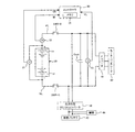
本発明の実施例1であるバッテリシステムについて説明する。図1は、本実施例であるバッテリシステムの構成を示す図である。本実施例のバッテリシステムは、車両に搭載されている。この車両としては、電気自動車やハイブリッド自動車がある。電気自動車は、車両を走行させる動力源として、後述するメインバッテリだけを備えている。ハイブリッド自動車は、車両を走行させる動力源として、後述するメインバッテリの他に、エンジン又は燃料電池を備えている。 A battery system that is Embodiment 1 of the present invention will be described. FIG. 1 is a diagram illustrating a configuration of a battery system according to the present embodiment. The battery system of this embodiment is mounted on a vehicle. Such vehicles include electric vehicles and hybrid vehicles. The electric vehicle includes only a main battery described later as a power source for running the vehicle. The hybrid vehicle includes an engine or a fuel cell as a power source for running the vehicle, in addition to a main battery described later.
メインバッテリ(本発明の高圧バッテリに相当する)10は、直列に接続された複数の単電池11を有する。単電池11としては、ニッケル水素電池やリチウムイオン電池などの二次電池が用いられる。また、二次電池の代わりに、電気二重層キャパシタを用いることもできる。メインバッテリ10には、並列に接続された複数の単電池11が含まれていてもよい。
A main battery (corresponding to a high voltage battery of the present invention) 10 has a plurality of single cells 11 connected in series. As the cell 11, a secondary battery such as a nickel metal hydride battery or a lithium ion battery is used. In addition, an electric double layer capacitor can be used instead of the secondary battery. The
電圧センサ21は、メインバッテリ10の電圧値VBを検出し、検出結果(電圧値VB)をコントローラ30に出力する。電流センサ22は、メインバッテリ10の電流値IBを検出し、検出結果(電流値IB)をコントローラ30に出力する。コントローラ30は、メモリ31を有しており、メモリ31には各種の情報が記憶されている。
The voltage sensor 21 detects the voltage value VB of the
メインバッテリ10の正極端子には正極ラインPLが接続され、メインバッテリ10の負極端子には負極ラインNLが接続されている。メインバッテリ10は、正極ラインPLおよび負極ラインNLを介して、インバータ41と接続されている。正極ラインPLには、システムメインリレーSMR−Bが設けられており、負極ラインNLには、システムメインリレーSMR−Gが設けられている。システムメインリレーSMR−B,SMR−Gは、コントローラ30からの制御信号を受けることにより、オンおよびオフの間で切り替わる。
A positive line PL is connected to the positive terminal of the
正極ラインPLおよび負極ラインNLには、コンデンサ(平滑コンデンサ)Coutが接続されている。具体的には、コンデンサCoutの一端は、システムメインリレーSMR−Bおよびインバータ41を接続する正極ラインPLに接続されている。また、コンデンサCoutの他端は、システムメインリレーSMR−Gおよびインバータ41を接続する負極ラインNLに接続されている。電圧センサ23は、コンデンサCoutの電圧値VLを検出し、検出結果(電圧値VL)をコントローラ30に出力する。
A capacitor (smoothing capacitor) Cout is connected to the positive electrode line PL and the negative electrode line NL. Specifically, one end of the capacitor Cout is connected to the positive line PL that connects the system main relay SMR-B and the
インバータ41は、メインバッテリ10から出力された直流電力を交流電力に変換し、交流電力をモータ・ジェネレータ(本発明の負荷に相当する)42に出力する。モータ・ジェネレータ42は、インバータ41から出力された交流電力を受けて、車両の走行に用いられる運動エネルギを生成する。モータ・ジェネレータ42は、車輪と接続されており、モータ・ジェネレータ42が生成した運動エネルギを車輪に伝達することにより、車両を走行させることができる。
The
モータ・ジェネレータ42は、車両の制動時に発生する運動エネルギを電気エネルギ(交流電力)に変換する。インバータ41は、モータ・ジェネレータ42が生成した交流電力を直流電力に変換し、直流電力をメインバッテリ10に出力する。これにより、回生電力をメインバッテリ10に蓄えることができる。
The motor /
正極ラインPLおよび負極ラインNLには、双方向型のDC/DCコンバータ50が接続されている。具体的には、DC/DCコンバータ50は、システムメインリレーSMR−Bおよびインバータ41を接続する正極ラインPLと、システムメインリレーSMR−Gおよびインバータ41を接続する負極ラインNLとに接続されている。
A bidirectional DC /
システムメインリレーSMR−B,SMR−Gがオンであるとき、DC/DCコンバータ50は、メインバッテリ10の電圧値VBを降圧し、降圧後の電力を補機バッテリ(本発明の低圧バッテリに相当する)43や補機44に出力する。メインバッテリ10からの電力を補機バッテリ43に供給することにより、補機バッテリ43を充電することができる。
When the system main relays SMR-B and SMR-G are on, the DC /
また、メインバッテリ10からの電力を補機44に供給することにより、補機44を動作させることができる。補機44には、補機バッテリ43からの電力を供給することもできる。補機バッテリ43は、コントローラ30やシステムメインリレーSMR−B,SMR−Gを動作させるための電源となる。
In addition, the
補機バッテリ43としては、鉛蓄電池やニッケル水素電池などの二次電池が用いられる。補機バッテリ43の電圧値VAは、補機バッテリ43の充放電に応じて変化し、電圧値VBは、メインバッテリ10の充放電に応じて変化する。ここで、電圧値VA,VBが変化しても、電圧値VAは電圧値VBよりも低くなる。
As the
また、電圧値VAが基準電圧値に維持されるように、補機バッテリ43の充電が制御される。具体的には、補機バッテリ43の放電によって電圧値VAが基準電圧値よりも低下したときには、電圧値VAが基準電圧値に到達するように、補機バッテリ43の充電が行われる。補機バッテリ43の出力電力は補機44に供給されるため、補機44の動作電圧を確保するためには、電圧値VAを基準電圧値に維持する必要がある。
Further, charging of the
システムメインリレーSMR−B,SMR−Gをオフからオンに切り替える前において、DC/DCコンバータ50は、補機バッテリ43の電圧値VAを昇圧し、昇圧後の電力をコンデンサCoutに出力する。これにより、コンデンサCoutを充電することができる。
Before switching system main relays SMR-B and SMR-G from OFF to ON, DC /
上述したように、DC/DCコンバータ50は、降圧動作および昇圧動作を行うことができる。このDC/DCコンバータ50の動作は、コントローラ30によって制御される。後述するように、DC/DCコンバータ50は、降圧動作を行うアクティブクランプフォワードコンバータに対して、昇圧動作の機能を追加したものである。
As described above, the DC /
図1に示すバッテリシステムにおいて、システムメインリレーSMR−B,SMR−Gをオフからオンに切り替えると、メインバッテリ10からコンデンサCoutに突入電流が流れてしまう。そこで、本実施例では、システムメインリレーSMR−B,SMR−Gをオフからオンに切り替える前に、補機バッテリ43から出力された電力を用いて、コンデンサCoutを充電するようにしている。
In the battery system shown in FIG. 1, when the system main relays SMR-B and SMR-G are switched from OFF to ON, an inrush current flows from the
具体的には、コンデンサCoutの充電によって、電圧値VLを電圧値VBと等しくしたり、電圧値VLを電圧値VBに近づけたりしている。このようにコンデンサCoutを充電しておけば、システムメインリレーSMR−B,SMR−Gをオフからオンに切り替えたときに、メインバッテリ10からコンデンサCoutに突入電流が流れることを抑制できる。
Specifically, by charging the capacitor Cout, the voltage value VL is made equal to the voltage value VB, or the voltage value VL is brought close to the voltage value VB. If the capacitor Cout is charged in this way, it is possible to prevent an inrush current from flowing from the
なお、コンデンサCoutを充電するだけでなく、補機バッテリ43から出力された電力を用いて、メインバッテリ10を充電することもできる。ここで、システムメインリレーSMR−B,SMR−Gがオンであるときに、メインバッテリ10の充電が行われる。
Not only the capacitor Cout but also the
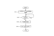
図2は、メインバッテリ10およびインバータ41を接続して、図1に示すバッテリシステムを起動状態(Ready-On)にするための処理を示す。ここで、図2に示す処理は、コントローラ30によって実行され、車両のイグニッションスイッチがオフからオンに切り替わったときに開始される。図2に示す処理を開始するとき、システムメインリレーSMR−B,SMR−Gはオフである。
FIG. 2 shows a process for connecting the
ステップS101において、コントローラ30は、DC/DCコンバータ50の昇圧動作を開始する。DC/DCコンバータ50が補機バッテリ43の電圧値VAを昇圧することにより、昇圧後の電力によってコンデンサCoutが充電され、電圧値VLが上昇する。ステップS101の処理を開始する前では、コンデンサCoutが放電されており、電圧値VLが0[V]となっている。
In step S101, the
ステップS102において、コントローラ30は、電圧センサ23によって検出された電圧値VLが、電圧センサ21によって検出された電圧値VB以上であるか否かを判別する。電圧値VLが電圧値VBよりも低いとき、DC/DCコンバータ50の昇圧動作が継続される。電圧値VLが電圧値VB以上であるとき、コントローラ30は、ステップS103において、DC/DCコンバータ50の昇圧動作を終了する。ステップS104において、コントローラ30は、システムメインリレーSMR−B,SMR−Gをオフからオンに切り替える。これにより、図1に示すバッテリシステムは起動状態となる。
In step S <b> 102, the
本実施例では、DC/DCコンバータ50の昇圧動作によって、電圧値VLが電圧値VB以上となるまでコンデンサCoutを充電しているが、これに限るものではない。具体的には、電圧値VLが電圧値VBよりも低い電圧値以上となるまで、コンデンサCoutを充電することもできる。
In the present embodiment, the capacitor Cout is charged until the voltage value VL becomes equal to or higher than the voltage value VB by the boosting operation of the DC /
なお、メインバッテリ10およびインバータ41の接続を遮断して、図1に示すバッテリシステムを停止状態(Ready-Off)にするとき、コントローラ30は、システムメインリレーSMR−B,SMR−Gをオンからオフに切り替える。このとき、コントローラ30は、コンデンサCoutを放電させて電圧値VLを0[V]にする。
When the connection between the
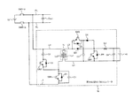
次に、DC/DCコンバータ50の回路構成について、図3を用いて説明する。図3では、DC/DCコンバータ50の回路構成に加えて、バッテリシステムの一部の構成も示している。
Next, the circuit configuration of the DC /
トランスTrの高圧側コイルLs2は、電力ラインL1,L2を介して、正極ラインPLおよび負極ラインNLに接続されている。ここで、高圧側コイルLs2の一端に接続された電力ラインL1は、正極ラインPLに接続され、高圧側コイルLs2の他端に接続された電力ラインL2は、負極ラインNLに接続されている。 The high-voltage coil Ls2 of the transformer Tr is connected to the positive electrode line PL and the negative electrode line NL via power lines L1 and L2. Here, the power line L1 connected to one end of the high voltage side coil Ls2 is connected to the positive electrode line PL, and the power line L2 connected to the other end of the high voltage side coil Ls2 is connected to the negative electrode line NL.
電力ラインL2には、第1スイッチ素子(トランジスタ)SW1が設けられており、第1スイッチ素子SW1は、高圧側コイルLs2と直列に接続されている。具体的には、第1スイッチ素子SW1のコレクタは、高圧側コイルLs2の他端と接続され、第1スイッチ素子SW1のエミッタは、負極ラインNLに接続されている。 The power line L2 is provided with a first switch element (transistor) SW1, and the first switch element SW1 is connected in series with the high-voltage side coil Ls2. Specifically, the collector of the first switch element SW1 is connected to the other end of the high-voltage side coil Ls2, and the emitter of the first switch element SW1 is connected to the negative electrode line NL.
第1スイッチ素子SW1には、第1ダイオードD1が逆並列に接続されている。本実施例および本発明において、逆並列の接続とは、スイッチ素子の通電方向と、ダイオードの通電方向とが逆方向となるように、スイッチ素子およびダイオードが並列に接続されていることである。 A first diode D1 is connected in antiparallel to the first switch element SW1. In the present embodiment and the present invention, the antiparallel connection means that the switch element and the diode are connected in parallel so that the energization direction of the switch element and the energization direction of the diode are opposite to each other.
具体的には、第1ダイオードD1のカソードが第1スイッチ素子SW1のコレクタに接続され、第1ダイオードD1のアノードが第1スイッチ素子SW1のエミッタに接続されている。ここで、第1スイッチ素子SW1がMOSFET(metal-oxide-semiconductor field-effect transistor)であるとき、第1ダイオードD1は、MOSFETに含まれる寄生ダイオードになる。また、第1スイッチ素子SW1には、第1コンデンサC1が並列に接続されている。 Specifically, the cathode of the first diode D1 is connected to the collector of the first switch element SW1, and the anode of the first diode D1 is connected to the emitter of the first switch element SW1. Here, when the first switch element SW1 is a MOSFET (metal-oxide-semiconductor field-effect transistor), the first diode D1 becomes a parasitic diode included in the MOSFET. A first capacitor C1 is connected in parallel to the first switch element SW1.
高圧側コイルLs2には、第2コンデンサC2および第2スイッチ素子(トランジスタ)SW2が並列に接続されており、第2コンデンサC2および第2スイッチ素子SW2は、直列に接続されている。ここで、第2コンデンサC2の一端は、電力ラインL1に接続されており、第2コンデンサC2の他端は、第2スイッチ素子SW2のコレクタに接続されている。第2スイッチ素子SW2のエミッタは、高圧側コイルLs2および第1スイッチ素子SW1の間の接続点に接続されている。 A second capacitor C2 and a second switch element (transistor) SW2 are connected in parallel to the high voltage side coil Ls2, and the second capacitor C2 and the second switch element SW2 are connected in series. Here, one end of the second capacitor C2 is connected to the power line L1, and the other end of the second capacitor C2 is connected to the collector of the second switch element SW2. The emitter of the second switch element SW2 is connected to a connection point between the high voltage side coil Ls2 and the first switch element SW1.
第2スイッチ素子SW2には、第2ダイオードD2が逆並列に接続されている。具体的には、第2ダイオードD2のカソードが第2スイッチ素子SW2のコレクタに接続され、第2ダイオードD2のアノードが第2スイッチ素子SW2のエミッタに接続されている。ここで、第2スイッチ素子SW2がMOSFETであるとき、第2ダイオードD2は、MOSFETに含まれる寄生ダイオードになる。 A second diode D2 is connected in antiparallel to the second switch element SW2. Specifically, the cathode of the second diode D2 is connected to the collector of the second switch element SW2, and the anode of the second diode D2 is connected to the emitter of the second switch element SW2. Here, when the second switch element SW2 is a MOSFET, the second diode D2 becomes a parasitic diode included in the MOSFET.
トランスTrの低圧側コイルLs1は、電力ラインL3,L4を介して、補機バッテリ43と接続されている。ここで、電力ラインL3は、低圧側コイルLs1の一端と、補機バッテリ43の正極端子とに接続されている。電力ラインL4は、低圧側コイルLs1の他端と、補機バッテリ43の負極端子とに接続されている。
The low voltage side coil Ls1 of the transformer Tr is connected to the
電力ラインL3には、第3ダイオードD3およびリアクトルLdが設けられている。ここで、第3ダイオードD3のアノードが低圧側コイルLs1の一端に接続され、第3ダイオードD3のカソードがリアクトルLdの一端に接続されている。リアクトルLdの他端は、補機バッテリ43の正極端子に接続されている。
The power line L3 is provided with a third diode D3 and a reactor Ld. Here, the anode of the third diode D3 is connected to one end of the low voltage side coil Ls1, and the cathode of the third diode D3 is connected to one end of the reactor Ld. The other end of the reactor Ld is connected to the positive terminal of the
第3ダイオードD3には、第3スイッチ素子(トランジスタ)SW3および第4ダイオードD4が並列に接続されており、第3スイッチ素子SW3および第4ダイオードD4は、直列に接続されている。ここで、第3スイッチ素子SW3のエミッタは、低圧側コイルLs1および第3ダイオードD3の間の接続点に接続されている。第3スイッチ素子SW3のコレクタには、第4ダイオードD4のカソードが接続されている。第4ダイオードD4のアノードは、第3ダイオードD3およびリアクトルLdの間の接続点に接続されている。 A third switch element (transistor) SW3 and a fourth diode D4 are connected in parallel to the third diode D3, and the third switch element SW3 and the fourth diode D4 are connected in series. Here, the emitter of the third switch element SW3 is connected to a connection point between the low voltage side coil Ls1 and the third diode D3. The cathode of the fourth diode D4 is connected to the collector of the third switch element SW3. The anode of the fourth diode D4 is connected to the connection point between the third diode D3 and the reactor Ld.
第3スイッチ素子SW3には、第5ダイオードD5が逆並列に接続されている。具体的には、第5ダイオードD5のカソードが第3スイッチ素子SW3のコレクタに接続され、第5ダイオードD5のアノードが第3スイッチ素子SW3のエミッタに接続されている。ここで、第3スイッチ素子SW3がMOSFETであるとき、第5ダイオードD5は、MOSFETに含まれる寄生ダイオードになる。 A fifth diode D5 is connected in antiparallel to the third switch element SW3. Specifically, the cathode of the fifth diode D5 is connected to the collector of the third switch element SW3, and the anode of the fifth diode D5 is connected to the emitter of the third switch element SW3. Here, when the third switch element SW3 is a MOSFET, the fifth diode D5 becomes a parasitic diode included in the MOSFET.
第3コンデンサC3の一端は、第3スイッチ素子SW3および第4ダイオードD4の間の接続点に接続されている。第3コンデンサC3の他端は、電力ラインL4に接続されている。ここで、第3コンデンサC3は、低圧側コイルLs1や補機バッテリ43に対して並列に接続されている。
One end of the third capacitor C3 is connected to a connection point between the third switch element SW3 and the fourth diode D4. The other end of the third capacitor C3 is connected to the power line L4. Here, the third capacitor C3 is connected in parallel to the low voltage side coil Ls1 and the
第4スイッチ素子(トランジスタ)SW4のコレクタは、第3ダイオードD3およびリアクトルLdの間の接続点に接続されているとともに、第4ダイオードD4のアノードに接続されている。第4スイッチ素子SW4のエミッタは、電力ラインL4に接続されている。第4スイッチ素子SW4には、第6ダイオードD6が逆並列に接続されている。具体的には、第6ダイオードD6のカソードが第4スイッチ素子SW4のコレクタに接続され、第6ダイオードD6のアノードが第4スイッチ素子SW4のエミッタに接続されている。ここで、第4スイッチ素子SW4がMOSFETであるとき、第6ダイオードD6は、MOSFETに含まれる寄生ダイオードになる。 The collector of the fourth switch element (transistor) SW4 is connected to the connection point between the third diode D3 and the reactor Ld, and is connected to the anode of the fourth diode D4. The emitter of the fourth switch element SW4 is connected to the power line L4. A sixth diode D6 is connected in antiparallel to the fourth switch element SW4. Specifically, the cathode of the sixth diode D6 is connected to the collector of the fourth switch element SW4, and the anode of the sixth diode D6 is connected to the emitter of the fourth switch element SW4. Here, when the fourth switch element SW4 is a MOSFET, the sixth diode D6 becomes a parasitic diode included in the MOSFET.
第4コンデンサC4は、補機バッテリ43に並列に接続されている。具体的には、第4コンデンサC4の一端は、リアクトルLdと補機バッテリ43の正極端子との間の接続点に接続されている。第4コンデンサC4の他端は、電力ラインL4に接続されている。
The fourth capacitor C4 is connected to the
上述したDC/DCコンバータ50は、アクティブクランプフォワードコンバータの回路構成を含んでおり、この回路構成によって降圧動作を行うことができる。また、DC/DCコンバータ50では、アクティブクランプフォワードコンバータの回路構成に対して、スイッチ素子SW3,SW4、ダイオードD4,D5および第3コンデンサC3を追加している。これにより、後述するように、DC/DCコンバータ50の昇圧動作を行うことができる。
The DC /
トランスTrにおいて、高圧側コイルLs2および低圧側コイルLs1の間の巻線比は、以下に説明するように設定される。 In the transformer Tr, the winding ratio between the high voltage side coil Ls2 and the low voltage side coil Ls1 is set as described below.
メインバッテリ10の電圧値VBは、メインバッテリ10の充放電によって変化し、下限電圧値VB_minに到達することがある。下限電圧値VB_minとは、メインバッテリ10の充放電を制御するときに許容される電圧値VBの下限値である。電圧値VBが下限電圧値VB_minに到達したときにも、DC/DCコンバータ50の降圧動作を行った後の電圧値は、補機バッテリ43の電圧値VA以上とする必要がある。また、DC/DCコンバータ50の降圧後における電力を補機44に供給するときには、補機44の動作電圧を確保するために、降圧動作後の電圧値を電圧値VA以上とする必要がある。
The voltage value VB of the
上述したように、電圧値VAは基準電圧値に維持されるため、DC/DCコンバータ50の降圧動作が行われた後の電圧値は、基準電圧値VA以上とする必要がある。このため、下限電圧値VB_minおよび基準電圧値VAに基づいて、低圧側コイルLs1および高圧側コイルLs2の間の巻線比(トランスTrの変圧比)が設定される。具体的には、低圧側コイルLs1の巻数をN1とし、高圧側コイルLs2の巻数をN2としたとき、巻線比(N2/N1)は、電圧値VB_minおよび基準電圧値VAの比(VB_min/VA)以下の値とすることができる。
As described above, since the voltage value VA is maintained at the reference voltage value, the voltage value after the step-down operation of the DC /
このように巻線比(N2/N1)を設定すると、トランスTrを用いた昇圧だけでは、下限電圧値VB_minよりも高い電圧値まで、電圧値VAを昇圧することができないことがある。このため、電圧値VBが下限電圧値VB_minよりも高いときには、補機バッテリ43を放電してコンデンサCoutを充電しても、電圧値VLを電圧値VBまで上昇させることができないことがある。電圧値VLが電圧値VBよりも低すぎると、上述したように、システムメインリレーSMR−B,SMR−Gをオンにしたときに、メインバッテリ10からコンデンサCoutに突入電流が流れてしまう。
When the winding ratio (N2 / N1) is set in this way, the voltage value VA may not be boosted to a voltage value higher than the lower limit voltage value VB_min only by boosting using the transformer Tr. For this reason, when voltage value VB is higher than lower limit voltage value VB_min, voltage value VL may not be raised to voltage value VB even if
そこで、本実施例では、リアクトルLdを用いて補機バッテリ43の電圧値VAを昇圧するとともに、この昇圧後の電圧値を、トランスTrを用いて更に昇圧している。これにより、DC/DCコンバータ50は、補機バッテリ43の電圧値VAを、下限電圧値VB_minよりも高い電圧値まで昇圧することができる。そして、補機バッテリ43の放電電力を用いてコンデンサCoutを充電するときには、電圧値VBが下限電圧値VB_minよりも高くても、コンデンサCoutの電圧値VLを電圧値VBまで上昇させることができる。
Therefore, in this embodiment, the voltage value VA of the
以下、DC/DCコンバータ50の昇圧動作について説明する。
Hereinafter, the boosting operation of the DC /
まず、昇圧動作を開始する前には、前回の昇圧動作によってトランスTrに蓄積された磁気エネルギをリセットさせる。ここで、コントローラ30は、スイッチ素子SW1〜SW4をオフにする。このとき、トランスTrの高圧側コイルLs2から第2ダイオードD2を介して第2コンデンサC2に電流が流れる。これにより、第2コンデンサC2の負電圧が上昇する。一方、補機バッテリ43の放電電流が、リアクトルLdおよび第4ダイオードD4を介して第3コンデンサC3に流れることにより、第3コンデンサC3の電圧値が上昇する。
First, before starting the boosting operation, the magnetic energy accumulated in the transformer Tr by the previous boosting operation is reset. Here, the
次に、コントローラ30は、スイッチ素子SW2,SW4をオフからオンに切り替える。ここで、トランスTrに磁気エネルギが蓄積されている間は、第2スイッチ素子SW2をオンにしても、第2コンデンサC2の負電圧が上昇し続ける。一方、第4スイッチ素子SW4をオンにすることにより、補機バッテリ43の放電電流がスイッチ素子SW4を流れ、リアクトルLdに磁気エネルギが蓄積される。
Next, the
トランスTrに蓄積された磁気エネルギが無くなると、第2コンデンサC2に蓄積された負の電荷が放電される。ここで、第2コンデンサC2の放電電流は、第2スイッチ素子SW2を介して、トランスTrの高圧側コイルLs2に流れる。 When the magnetic energy accumulated in the transformer Tr disappears, the negative charge accumulated in the second capacitor C2 is discharged. Here, the discharge current of the second capacitor C2 flows to the high-voltage side coil Ls2 of the transformer Tr via the second switch element SW2.
次に、コントローラ30は、第4スイッチ素子SW4をオンからオフに切り替える。これにより、リアクトルLdに蓄積された磁気エネルギが放出され、リアクトルLdから第4ダイオードD4を介して、第3コンデンサC3に電流が流れる。そして、第3コンデンサC3が充電され、第3コンデンサC3の電圧値が上昇する。第3コンデンサC3の電圧値は、補機バッテリ43の電圧値VAよりも高くなる。
Next, the
次に、コントローラ30は、第3スイッチ素子SW3をオフからオンに切り替える。第3スイッチ素子SW3がオンになると、第3コンデンサC3およびトランスTrの励磁インダクタンスによってLC回路が構成される。これにより、トランスTrの低圧側コイルLs1に励磁電流が流れ、低圧側コイルLs1の電圧値が上昇する。低圧側コイルLs1の電圧値が上昇すると、低圧側コイルLs1および高圧側コイルLs2の間の巻線比(昇圧比)に応じて、高圧側コイルLs2の電圧値が上昇する。このように、トランスTrによって、第3コンデンサC3の電圧が昇圧される。
Next, the
高圧側コイルLs2の電圧値が、低圧側コイルLs1の電圧値に対して、低圧側コイルLs1および高圧側コイルLs2の間の巻線比に応じた電圧値に到達すると、第3コンデンサC3および低圧側コイルLs1の漏れインダクタンスによってLC回路が構成される。これに伴い、高圧側コイルLs2からコンデンサCoutに電流が流れ、コンデンサCoutが充電される。そして、コンデンサCoutの電圧値VLが上昇する。ここで、コンデンサCoutの充電電流は、高圧側コイルLs2、コンデンサCoutおよび第1ダイオードD1を流れる。 When the voltage value of the high voltage side coil Ls2 reaches the voltage value corresponding to the winding ratio between the low voltage side coil Ls1 and the high voltage side coil Ls2 with respect to the voltage value of the low voltage side coil Ls1, the third capacitor C3 and the low voltage The LC circuit is configured by the leakage inductance of the side coil Ls1. Along with this, a current flows from the high voltage side coil Ls2 to the capacitor Cout, and the capacitor Cout is charged. Then, the voltage value VL of the capacitor Cout increases. Here, the charging current of the capacitor Cout flows through the high voltage side coil Ls2, the capacitor Cout, and the first diode D1.
コンデンサCoutを充電している間、第3コンデンサC3の放電によって第3コンデンサC3の電圧値が低下する。これに伴い、高圧側コイルLs2の電圧値が低下し、コンデンサCoutの充電が停止する。図2に示す処理を行うとき、コントローラ30は、スイッチ素子SW3,SW4のオンおよびオフを制御することにより、コンデンサCoutの電圧値VLを電圧値VBに到達させることができる。
While the capacitor Cout is being charged, the voltage value of the third capacitor C3 decreases due to the discharge of the third capacitor C3. Along with this, the voltage value of the high voltage side coil Ls2 decreases, and charging of the capacitor Cout stops. When the processing shown in FIG. 2 is performed, the
次に、DC/DCコンバータ50の降圧動作について説明する。この降圧動作は、アクティブクランプフォワードコンバータの降圧動作と同様であり、以下、簡単に説明する。降圧動作を開始するとき、スイッチ素子SW1〜SW4はオフである。
Next, the step-down operation of the DC /
コントローラ30は、第1スイッチ素子SW1をオンにする。これにより、メインバッテリ10からトランスTrの高圧側コイルLs2に励磁電流が流れる。そして、トランスTrに発生する起電力によって、第3ダイオードD3に電流が流れる。トランスTrでは、高圧側コイルLs2および低圧側コイルLs1の間の巻線比(降圧比)に応じて、メインバッテリ10の電圧値VBが降圧される。
The
また、第3ダイオードD3に電流が流れるとき、ダイオードD3,D6によって整流され、第4コンデンサC4によって平滑化された直流電力が補機バッテリ43に供給される。なお、補機バッテリ43を充電するとき、リアクトルLdに電流が流れる。ここで、リアクトルLdに蓄積された磁気エネルギは、第6ダイオードD6を含む電流経路において、放出することができる。
Further, when current flows through the third diode D3, the DC power rectified by the diodes D3 and D6 and smoothed by the fourth capacitor C4 is supplied to the
次に、コントローラ30は、第1スイッチ素子SW1をオンからオフに切り替える。これにより、トランスTrの高圧側コイルLs2から第1コンデンサC1に電流が流れ、第1コンデンサC1が充電される。第1コンデンサC1が充電されているときも、第3ダイオードD3に電流が流れている。第1コンデンサC1の電圧値が所定電圧値に到達すると、高圧側コイルLs2から第2ダイオードD2を介して第2コンデンサC2に電流が流れ、第2コンデンサC2が充電される。ここで、高圧側コイルLs2には、第2コンデンサC2の電圧が逆方向に印加されるため、高圧側コイルLs2に流れる励磁電流が減少する。
Next, the
コントローラ30は、第2ダイオードD2が導通状態の間に、第2スイッチ素子SW2をオフからオンに切り替える。これにより、第2コンデンサC2に蓄積された電荷が高圧側コイルLs2に放出され、高圧側コイルLs2に流れる励磁電流がさらに減少する。これに伴い、トランスTrに蓄積された磁気エネルギがリセットされる。コントローラ30が第2スイッチ素子SW2をオンからオフに切り替えることにより、第1コンデンサC1に蓄積された電荷を放出させることができる。第1コンデンサC1の放電電流は、高圧側コイルLs2に流れる。これにより、第1コンデンサC1の放電が終了する。
The
上述したように、コントローラ30はスイッチ素子SW1,SW2のオンおよびオフを制御することにより、メインバッテリ10からトランスTrを介して補機バッテリ43に一定の直流電圧を出力することができる。
As described above, the
本実施例によれば、下限電圧値VB_minを考慮して、トランスTrの変圧比(降圧比)を設定しているため、電圧値VBが変化しても、DC/DCコンバータ50から補機バッテリ43に出力される電圧値を、電圧値VA以上にすることができる。
According to the present embodiment, since the transformation ratio (step-down ratio) of the transformer Tr is set in consideration of the lower limit voltage value VB_min, the auxiliary battery is connected from the DC /
一方、昇圧動作を行うときには、リアクトルLdを用いて補機バッテリ43の電圧値VAを昇圧した後に、トランスTrによって更に昇圧している。これにより、トランスTrの変圧比(昇圧比)よりも大きな昇圧比において、補機バッテリ43の電圧値VBを昇圧することができる。したがって、電圧値VBが変化しても、DC/DCコンバータ50からコンデンサCoutに出力される電圧値を電圧値VB以上にすることができる。
On the other hand, when the boosting operation is performed, the voltage value VA of the
10:メインバッテリ、11:単電池、21:電圧センサ、22:電流センサ、
23:電圧センサ、30:コントローラ、31:メモリ、41:インバータ、
42:モータ・ジェネレータ、43:補機バッテリ、44:補機、
50:DC/DCコンバータ
10: main battery, 11: single cell, 21: voltage sensor, 22: current sensor,
23: Voltage sensor, 30: Controller, 31: Memory, 41: Inverter,
42: Motor generator 43: Auxiliary battery 44: Auxiliary machine
50: DC / DC converter
Claims (2)
前記高圧バッテリに接続される高圧側コイルと、前記低圧バッテリに接続される低圧側コイルとを備えたトランスと、
前記高圧側コイルと直列に接続された第1スイッチ素子と、
前記第1スイッチ素子と逆並列に接続された第1ダイオードと、
前記第1スイッチ素子と並列に接続された第1コンデンサと、
前記高圧側コイルと並列に接続され、互いに直列に接続された第2スイッチ素子および第2コンデンサと、
前記第2スイッチ素子と逆並列に接続された第2ダイオードと、
前記低圧側コイルの一端にアノードが接続された第3ダイオードと、
一端が前記第3ダイオードのカソードに接続され、他端が前記低圧バッテリの正極端子に接続されたリアクトルと、
前記低圧側コイルおよび前記第3ダイオードの間の接続点に一端が接続された第3スイッチ素子と、
カソードが前記第3スイッチ素子の他端に接続され、アノードが前記第3ダイオードおよび前記リアクトルの間の接続点に接続された第4ダイオードと、
前記第3スイッチ素子と逆並列に接続された第5ダイオードと、
前記第3スイッチ素子および前記第4ダイオードの間の接続点に一端が接続され、前記低圧側コイルおよび前記低圧バッテリと並列に接続された第3コンデンサと、
前記第3ダイオードおよび前記リアクトルの間の接続点および前記第4ダイオードのアノードに一端が接続され、前記低圧側コイルおよび前記低圧バッテリと並列に接続された第4スイッチ素子と、
前記第4スイッチ素子と逆並列に接続された第6ダイオードと、
を有することを特徴とするDC/DCコンバータ。 A DC / DC converter for stepping down the voltage value of the high voltage battery and boosting the voltage value of the low voltage battery indicating a voltage value lower than the high voltage battery,
A transformer comprising a high voltage side coil connected to the high voltage battery, and a low voltage side coil connected to the low voltage battery;
A first switch element connected in series with the high-voltage side coil;
A first diode connected in antiparallel with the first switch element;
A first capacitor connected in parallel with the first switch element;
A second switch element and a second capacitor connected in parallel with the high-voltage side coil and connected in series with each other;
A second diode connected in anti-parallel with the second switch element;
A third diode having an anode connected to one end of the low-voltage side coil;
A reactor having one end connected to the cathode of the third diode and the other end connected to the positive terminal of the low-voltage battery;
A third switch element having one end connected to a connection point between the low-voltage coil and the third diode;
A fourth diode having a cathode connected to the other end of the third switch element and an anode connected to a connection point between the third diode and the reactor;
A fifth diode connected in antiparallel with the third switch element;
A third capacitor having one end connected to a connection point between the third switch element and the fourth diode, and connected in parallel with the low-voltage coil and the low-voltage battery;
A fourth switching element having one end connected to a connection point between the third diode and the reactor and an anode of the fourth diode, and connected in parallel to the low-voltage coil and the low-voltage battery;
A sixth diode connected in antiparallel with the fourth switch element;
A DC / DC converter characterized by comprising:
正極ラインおよび負極ラインを介して前記高圧バッテリと接続される負荷と、
前記正極ラインおよび前記負極ラインのそれぞれに設けられたリレーと、
前記正極ラインおよび前記負極ラインに接続された平滑コンデンサと、
前記DC/DCコンバータおよび前記リレーを制御するコントローラと、を有し、
前記コントローラは、前記リレーをオフからオンに切り替える前に、前記DC/DCコンバータによって前記低圧バッテリの電圧値を昇圧し、昇圧後の電力を用いて前記平滑コンデンサを充電することを特徴とする蓄電システム。
A DC / DC converter according to claim 1;
A load connected to the high-voltage battery via a positive electrode line and a negative electrode line;
A relay provided in each of the positive line and the negative line;
A smoothing capacitor connected to the positive line and the negative line;
A controller for controlling the DC / DC converter and the relay,
The controller boosts the voltage value of the low-voltage battery by the DC / DC converter and charges the smoothing capacitor using the boosted power before switching the relay from OFF to ON. system.
Priority Applications (5)
| Application Number | Priority Date | Filing Date | Title |
|---|---|---|---|
| JP2014067997A JP6228059B2 (en) | 2014-03-28 | 2014-03-28 | DC / DC converter and battery system |
| EP15721822.3A EP3123604B1 (en) | 2014-03-28 | 2015-03-13 | Dc/dc converter and electrical storage system |
| CN201580016229.7A CN106134058B (en) | 2014-03-28 | 2015-03-13 | DC/DC converters and accumulating system |
| PCT/IB2015/000325 WO2015145232A1 (en) | 2014-03-28 | 2015-03-13 | Dc/dc converter and electrical storage system |
| US15/129,123 US9954454B2 (en) | 2014-03-28 | 2015-03-13 | DC/DC converter and electrical storage system |
Applications Claiming Priority (1)
| Application Number | Priority Date | Filing Date | Title |
|---|---|---|---|
| JP2014067997A JP6228059B2 (en) | 2014-03-28 | 2014-03-28 | DC / DC converter and battery system |
Publications (2)
| Publication Number | Publication Date |
|---|---|
| JP2015192525A true JP2015192525A (en) | 2015-11-02 |
| JP6228059B2 JP6228059B2 (en) | 2017-11-08 |
Family
ID=53175544
Family Applications (1)
| Application Number | Title | Priority Date | Filing Date |
|---|---|---|---|
| JP2014067997A Active JP6228059B2 (en) | 2014-03-28 | 2014-03-28 | DC / DC converter and battery system |
Country Status (5)
| Country | Link |
|---|---|
| US (1) | US9954454B2 (en) |
| EP (1) | EP3123604B1 (en) |
| JP (1) | JP6228059B2 (en) |
| CN (1) | CN106134058B (en) |
| WO (1) | WO2015145232A1 (en) |
Cited By (6)
| Publication number | Priority date | Publication date | Assignee | Title |
|---|---|---|---|---|
| WO2019026149A1 (en) * | 2017-07-31 | 2019-02-07 | 日産自動車株式会社 | Power supply system and control method therefor |
| WO2019026150A1 (en) * | 2017-07-31 | 2019-02-07 | 日産自動車株式会社 | POWER SUPPLY SYSTEM AND ITS CONTROL METHOD |
| CN113165523A (en) * | 2020-08-10 | 2021-07-23 | 深圳欣锐科技股份有限公司 | Charging circuit, device and electric automobile |
| JP2022514412A (en) * | 2018-12-21 | 2022-02-10 | ロベルト・ボッシュ・ゲゼルシャフト・ミト・ベシュレンクテル・ハフツング | DC voltage converter for transmitting power from the primary side to the secondary side of the DC voltage converter, or vice versa. |
| JPWO2024004140A1 (en) * | 2022-06-30 | 2024-01-04 | ||
| WO2026018376A1 (en) * | 2024-07-18 | 2026-01-22 | 日産自動車株式会社 | Power supply control device and power supply control method |
Families Citing this family (5)
| Publication number | Priority date | Publication date | Assignee | Title |
|---|---|---|---|---|
| KR20170052095A (en) * | 2015-11-03 | 2017-05-12 | 현대자동차주식회사 | Battery control system and method for detecting fusion of relay |
| KR102699251B1 (en) * | 2016-11-22 | 2024-08-28 | 현대자동차주식회사 | Vehicle, DC-DC Converter for Vehicle, and Controlling Method of DC-DC Converter for Vehicle |
| JP6503413B2 (en) * | 2017-05-31 | 2019-04-17 | 本田技研工業株式会社 | DC / DC converter and electrical equipment |
| KR102394826B1 (en) * | 2018-02-14 | 2022-05-04 | 주식회사 엘지에너지솔루션 | Power supply circuit for energy transfer between battery and smoothing capacitor and battery management system including the same |
| JP7044687B2 (en) * | 2018-11-09 | 2022-03-30 | トヨタ自動車株式会社 | Vehicle power supply |
Citations (8)
| Publication number | Priority date | Publication date | Assignee | Title |
|---|---|---|---|---|
| JPH0472882U (en) * | 1990-11-06 | 1992-06-26 | ||
| JP2003061209A (en) * | 2001-08-10 | 2003-02-28 | Honda Motor Co Ltd | Power supply for vehicle |
| JP2007166887A (en) * | 2005-11-18 | 2007-06-28 | Denso Corp | Control method of DC / DC converter |
| JP2007329996A (en) * | 2006-06-06 | 2007-12-20 | Sharp Corp | Switching power supply device |
| US20080074905A1 (en) * | 2006-09-22 | 2008-03-27 | Kabushiki Kaisha Toyota Jidoshokki | Method for Controlling Bidirectional DC-DC Converter |
| JP2009177940A (en) * | 2008-01-24 | 2009-08-06 | Shindengen Electric Mfg Co Ltd | Bidirectional dc/dc converter |
| JP2012182894A (en) * | 2011-03-01 | 2012-09-20 | Omron Automotive Electronics Co Ltd | Power conversion apparatus and power control method |
| JP2014135825A (en) * | 2013-01-09 | 2014-07-24 | Toyota Motor Corp | Power storage system |
Family Cites Families (7)
| Publication number | Priority date | Publication date | Assignee | Title |
|---|---|---|---|---|
| WO1993024987A1 (en) * | 1992-06-02 | 1993-12-09 | Astec International Limited | Dual active clamp power converter |
| JP4719567B2 (en) * | 2005-12-21 | 2011-07-06 | 日立オートモティブシステムズ株式会社 | Bidirectional DC-DC converter and control method thereof |
| CN100514817C (en) * | 2007-04-29 | 2009-07-15 | 北京新雷能有限责任公司 | Zero voltage switch active clamp positive and negative violent changer |
| US8058743B2 (en) * | 2008-09-30 | 2011-11-15 | GM Global Technology Operations LLC | Automotive electrical system for coupling power converters with a transformer |
| CN102522766B (en) * | 2011-11-04 | 2014-12-24 | 浙江昱能科技有限公司 | Flyback type miniature photovoltaic grid connected inverter with power decoupling circuit and control method thereof |
| JP6022889B2 (en) * | 2012-10-22 | 2016-11-09 | Ntn株式会社 | Vibrating bowl feeder |
| KR101734641B1 (en) * | 2015-04-14 | 2017-05-11 | 현대자동차주식회사 | Charging device of vehicle |
-
2014
- 2014-03-28 JP JP2014067997A patent/JP6228059B2/en active Active
-
2015
- 2015-03-13 EP EP15721822.3A patent/EP3123604B1/en active Active
- 2015-03-13 WO PCT/IB2015/000325 patent/WO2015145232A1/en not_active Ceased
- 2015-03-13 US US15/129,123 patent/US9954454B2/en active Active
- 2015-03-13 CN CN201580016229.7A patent/CN106134058B/en not_active Expired - Fee Related
Patent Citations (8)
| Publication number | Priority date | Publication date | Assignee | Title |
|---|---|---|---|---|
| JPH0472882U (en) * | 1990-11-06 | 1992-06-26 | ||
| JP2003061209A (en) * | 2001-08-10 | 2003-02-28 | Honda Motor Co Ltd | Power supply for vehicle |
| JP2007166887A (en) * | 2005-11-18 | 2007-06-28 | Denso Corp | Control method of DC / DC converter |
| JP2007329996A (en) * | 2006-06-06 | 2007-12-20 | Sharp Corp | Switching power supply device |
| US20080074905A1 (en) * | 2006-09-22 | 2008-03-27 | Kabushiki Kaisha Toyota Jidoshokki | Method for Controlling Bidirectional DC-DC Converter |
| JP2009177940A (en) * | 2008-01-24 | 2009-08-06 | Shindengen Electric Mfg Co Ltd | Bidirectional dc/dc converter |
| JP2012182894A (en) * | 2011-03-01 | 2012-09-20 | Omron Automotive Electronics Co Ltd | Power conversion apparatus and power control method |
| JP2014135825A (en) * | 2013-01-09 | 2014-07-24 | Toyota Motor Corp | Power storage system |
Cited By (14)
| Publication number | Priority date | Publication date | Assignee | Title |
|---|---|---|---|---|
| WO2019026149A1 (en) * | 2017-07-31 | 2019-02-07 | 日産自動車株式会社 | Power supply system and control method therefor |
| WO2019026150A1 (en) * | 2017-07-31 | 2019-02-07 | 日産自動車株式会社 | POWER SUPPLY SYSTEM AND ITS CONTROL METHOD |
| EP3664205A4 (en) * | 2017-07-31 | 2020-08-19 | Nissan Motor Co., Ltd. | POWER SUPPLY SYSTEM AND CONTROL PROCEDURES FOR IT |
| JPWO2019026149A1 (en) * | 2017-07-31 | 2020-08-27 | 日産自動車株式会社 | Power supply system and control method thereof |
| US10998748B2 (en) | 2017-07-31 | 2021-05-04 | Nissan Motor Co., Ltd. | Electric power supply system and control method therefor |
| JP2022514412A (en) * | 2018-12-21 | 2022-02-10 | ロベルト・ボッシュ・ゲゼルシャフト・ミト・ベシュレンクテル・ハフツング | DC voltage converter for transmitting power from the primary side to the secondary side of the DC voltage converter, or vice versa. |
| JP7177940B2 (en) | 2018-12-21 | 2022-11-24 | ロベルト・ボッシュ・ゲゼルシャフト・ミト・ベシュレンクテル・ハフツング | DC voltage converter for bi-directional transmission of power from the primary side of the DC voltage converter to the secondary side and vice versa |
| US11764696B2 (en) | 2018-12-21 | 2023-09-19 | Robert Bosch Gmbh | Direct-current voltage converter for bidirectional electrical power transmission from a primary side to a secondary side of the direct-current voltage converter or vice versa |
| CN113165523A (en) * | 2020-08-10 | 2021-07-23 | 深圳欣锐科技股份有限公司 | Charging circuit, device and electric automobile |
| WO2022032439A1 (en) * | 2020-08-10 | 2022-02-17 | 深圳欣锐科技股份有限公司 | Charging circuit and device, and electric vehicle |
| CN113165523B (en) * | 2020-08-10 | 2022-12-23 | 深圳欣锐科技股份有限公司 | Charging circuit, device and electric automobile |
| JPWO2024004140A1 (en) * | 2022-06-30 | 2024-01-04 | ||
| JP7769893B2 (en) | 2022-06-30 | 2025-11-14 | 株式会社オートネットワーク技術研究所 | In-vehicle shutoff control device |
| WO2026018376A1 (en) * | 2024-07-18 | 2026-01-22 | 日産自動車株式会社 | Power supply control device and power supply control method |
Also Published As
| Publication number | Publication date |
|---|---|
| CN106134058B (en) | 2018-11-02 |
| US9954454B2 (en) | 2018-04-24 |
| CN106134058A (en) | 2016-11-16 |
| EP3123604B1 (en) | 2019-04-24 |
| JP6228059B2 (en) | 2017-11-08 |
| WO2015145232A1 (en) | 2015-10-01 |
| US20170110975A1 (en) | 2017-04-20 |
| EP3123604A1 (en) | 2017-02-01 |
Similar Documents
| Publication | Publication Date | Title |
|---|---|---|
| JP6228059B2 (en) | DC / DC converter and battery system | |
| JP6403024B2 (en) | In-vehicle power supply | |
| KR101284331B1 (en) | Recharge systen for green car and method thereof | |
| CN101712284B (en) | Automotive electrical system for coupling power converters with a transformer | |
| CN107925099A (en) | Power regulation system and its control method | |
| JP2018148637A (en) | Charger and on-vehicle power supply | |
| JP2009254169A (en) | Power supply system | |
| JP6702132B2 (en) | Fuel cell car power supply system | |
| JP6300664B2 (en) | Railway vehicle power circuit | |
| KR102730538B1 (en) | Electric power system for vehicle and method for controlling the same | |
| JP2017022805A (en) | Electric car | |
| JP2014135825A (en) | Power storage system | |
| JP6428524B2 (en) | Vehicle power supply system | |
| WO2011055559A1 (en) | Power supply system | |
| CN112297944A (en) | Vehicle, power battery system of vehicle and control method thereof | |
| JP6962379B2 (en) | Power storage device | |
| JP2014204541A (en) | Control device | |
| JP5810945B2 (en) | Power storage system | |
| JP7718601B2 (en) | Power conversion device and program | |
| JP5925643B2 (en) | In-vehicle power control device | |
| JP5644131B2 (en) | Power supply device and power supply device control method | |
| JP2013102590A (en) | Power supply device for vehicles | |
| JP6319144B2 (en) | Electric car | |
| JP5981278B2 (en) | In-vehicle power control device | |
| JP5522091B2 (en) | Power supply |
Legal Events
| Date | Code | Title | Description |
|---|---|---|---|
| A621 | Written request for application examination |
Free format text: JAPANESE INTERMEDIATE CODE: A621 Effective date: 20160511 |
|
| A977 | Report on retrieval |
Free format text: JAPANESE INTERMEDIATE CODE: A971007 Effective date: 20170223 |
|
| A131 | Notification of reasons for refusal |
Free format text: JAPANESE INTERMEDIATE CODE: A131 Effective date: 20170307 |
|
| A521 | Request for written amendment filed |
Free format text: JAPANESE INTERMEDIATE CODE: A523 Effective date: 20170330 |
|
| A131 | Notification of reasons for refusal |
Free format text: JAPANESE INTERMEDIATE CODE: A131 Effective date: 20170711 |
|
| A521 | Request for written amendment filed |
Free format text: JAPANESE INTERMEDIATE CODE: A523 Effective date: 20170906 |
|
| TRDD | Decision of grant or rejection written | ||
| A01 | Written decision to grant a patent or to grant a registration (utility model) |
Free format text: JAPANESE INTERMEDIATE CODE: A01 Effective date: 20170919 |
|
| A61 | First payment of annual fees (during grant procedure) |
Free format text: JAPANESE INTERMEDIATE CODE: A61 Effective date: 20171012 |
|
| R151 | Written notification of patent or utility model registration |
Ref document number: 6228059 Country of ref document: JP Free format text: JAPANESE INTERMEDIATE CODE: R151 |
|
| R250 | Receipt of annual fees |
Free format text: JAPANESE INTERMEDIATE CODE: R250 |
|
| R250 | Receipt of annual fees |
Free format text: JAPANESE INTERMEDIATE CODE: R250 |
|
| R250 | Receipt of annual fees |
Free format text: JAPANESE INTERMEDIATE CODE: R250 |
|
| R250 | Receipt of annual fees |
Free format text: JAPANESE INTERMEDIATE CODE: R250 |
|
| R250 | Receipt of annual fees |
Free format text: JAPANESE INTERMEDIATE CODE: R250 |
|
| R250 | Receipt of annual fees |
Free format text: JAPANESE INTERMEDIATE CODE: R250 |