JP2015196600A - Material management system and transport robot - Google Patents
Material management system and transport robot Download PDFInfo
- Publication number
- JP2015196600A JP2015196600A JP2014225432A JP2014225432A JP2015196600A JP 2015196600 A JP2015196600 A JP 2015196600A JP 2014225432 A JP2014225432 A JP 2014225432A JP 2014225432 A JP2014225432 A JP 2014225432A JP 2015196600 A JP2015196600 A JP 2015196600A
- Authority
- JP
- Japan
- Prior art keywords
- robot
- transport
- shelf
- request
- time
- Prior art date
- Legal status (The legal status is an assumption and is not a legal conclusion. Google has not performed a legal analysis and makes no representation as to the accuracy of the status listed.)
- Granted
Links
Images






Classifications
-
- G—PHYSICS
- G05—CONTROLLING; REGULATING
- G05D—SYSTEMS FOR CONTROLLING OR REGULATING NON-ELECTRIC VARIABLES
- G05D1/00—Control of position, course, altitude or attitude of land, water, air or space vehicles, e.g. using automatic pilots
- G05D1/60—Intended control result
- G05D1/65—Following a desired speed profile
-
- G—PHYSICS
- G05—CONTROLLING; REGULATING
- G05D—SYSTEMS FOR CONTROLLING OR REGULATING NON-ELECTRIC VARIABLES
- G05D1/00—Control of position, course, altitude or attitude of land, water, air or space vehicles, e.g. using automatic pilots
- G05D1/60—Intended control result
- G05D1/644—Optimisation of travel parameters, e.g. of energy consumption, journey time or distance
- G05D1/6445—Optimisation of travel parameters, e.g. of energy consumption, journey time or distance for optimising payload operation, e.g. camera or spray coverage
-
- G—PHYSICS
- G05—CONTROLLING; REGULATING
- G05D—SYSTEMS FOR CONTROLLING OR REGULATING NON-ELECTRIC VARIABLES
- G05D1/00—Control of position, course, altitude or attitude of land, water, air or space vehicles, e.g. using automatic pilots
- G05D1/60—Intended control result
- G05D1/648—Performing a task within a working area or space, e.g. cleaning
- G05D1/6484—Performing a task within a working area or space, e.g. cleaning by taking into account parameters or characteristics of the working area or space, e.g. size or shape
- G05D1/6485—Performing a task within a working area or space, e.g. cleaning by taking into account parameters or characteristics of the working area or space, e.g. size or shape by taking into account surface type, e.g. carpeting
-
- G—PHYSICS
- G05—CONTROLLING; REGULATING
- G05D—SYSTEMS FOR CONTROLLING OR REGULATING NON-ELECTRIC VARIABLES
- G05D2105/00—Specific applications of the controlled vehicles
- G05D2105/20—Specific applications of the controlled vehicles for transportation
- G05D2105/28—Specific applications of the controlled vehicles for transportation of freight
-
- G—PHYSICS
- G05—CONTROLLING; REGULATING
- G05D—SYSTEMS FOR CONTROLLING OR REGULATING NON-ELECTRIC VARIABLES
- G05D2109/00—Types of controlled vehicles
- G05D2109/10—Land vehicles
Landscapes
- Engineering & Computer Science (AREA)
- Aviation & Aerospace Engineering (AREA)
- Radar, Positioning & Navigation (AREA)
- Remote Sensing (AREA)
- Physics & Mathematics (AREA)
- General Physics & Mathematics (AREA)
- Automation & Control Theory (AREA)
- Warehouses Or Storage Devices (AREA)
- Control Of Position, Course, Altitude, Or Attitude Of Moving Bodies (AREA)
Abstract
Description
本開示は、建物内の物を管理し運搬するサービスを実現するシステム、装置、および制御方法に関する。 The present disclosure relates to a system, an apparatus, and a control method for realizing a service for managing and transporting an object in a building.
近年、建物内における複数の機器がネットワークにつながり、クラウド上の計算リソースを使ってそれらの機器を制御することが可能になってきている。ユーザの生活状態に合わせた細やかな制御を行うことにより、生活の利便性が向上している。しかしながら、物を運ぶ、物をしまうといった物の管理については、ユーザ自身が手を動かす必要がある場合が多く、利便性向上の余地が残る。 In recent years, a plurality of devices in a building are connected to a network, and it has become possible to control these devices using computing resources on the cloud. Convenience of life is improved by performing fine control according to the life state of the user. However, the management of things such as carrying things and putting things away often requires the user to move their hands, leaving room for improvement in convenience.
一方、ここ数年、掃除ロボットなどの自律移動型のロボットが宅内に普及してきている。このような宅内を動き回る家電製品の登場により、今までの家電では実現できない新たな機能をユーザに提供できる可能性が増している。最近では、自律的に移動できることを活かして、ユーザの指示に従って物を取ってくる運搬ロボットの研究発表も行われている。 On the other hand, autonomous mobile robots such as cleaning robots have become popular in the past few years. With the advent of home appliances that move around in the house, there is an increased possibility of providing users with new functions that cannot be realized with conventional home appliances. Recently, research on transport robots that take objects according to user's instructions using the ability to move autonomously has been made.
特許文献1は、物を管理し、運搬するロボットの例を開示している。特許文献1は、可動部を有する棚が、要求された物を吐出口に移動させ、運搬ロボットに渡す機構を開示している。
本開示は、ユーザによる物の管理や物を運ぶ負担を軽減することで、より効率的に物の運搬と保管を実現するシステムを提供する。 The present disclosure provides a system that realizes the transportation and storage of objects more efficiently by reducing the burden of managing the objects and transporting the objects by the user.
本開示の一態様に係る物管理システムは、物を運搬する運搬ロボットと、物を保管する棚ロボットと、を備える。前記運搬ロボットは、ユーザから渡された物を前記棚ロボットまで運搬する要求、および、前記棚ロボットに保管されている物を前記ユーザまで運搬する要求の少なくとも一方を含む運搬要求を、前記ユーザから受け付ける入力インターフェースと、前記入力インターフェースが前記運搬要求を受け付けた後、前記運搬要求に基づく通知を前記棚ロボットに送信する第1通信回路と、前記第1通信回路が前記通知を送信した後、前記運搬ロボットを前記棚ロボットまで移動させる移動機構と、を有する。前記棚ロボットは、前記第1通信回路から送信された前記通知を受信する第2通信回路と、前記第2通信回路が前記通知を受信した後、前記運搬要求に係る物を、前記物の保管位置から前記運搬ロボットとの受け渡し位置まで移動させる、または、前記運搬ロボットから前記運搬要求に係る物を受け取って所定の保管位置に移動させるコンベヤー機構と、を有する。 An object management system according to an aspect of the present disclosure includes a transport robot that transports an object and a shelf robot that stores the object. The transport robot sends a transport request including at least one of a request for transporting an object delivered from a user to the shelf robot and a request for transporting an object stored in the shelf robot to the user from the user. An input interface to receive, a first communication circuit that transmits a notification based on the transport request to the shelf robot after the input interface has received the transport request, and after the first communication circuit transmits the notification, A moving mechanism for moving the transport robot to the shelf robot. The shelf robot is configured to store a second communication circuit that receives the notification transmitted from the first communication circuit, and an object related to the transport request after the second communication circuit receives the notification. A conveyor mechanism that moves from a position to a delivery position with the transport robot, or receives an object related to the transport request from the transport robot and moves it to a predetermined storage position.
上記の態様は、システム、方法、集積回路、コンピュータプログラム、または、記録媒体によって実現されてもよい。あるいは、システム、装置、方法、集積回路、コンピュータプログラムおよび記録媒体の任意な組み合わせによって実現されてもよい。 The above aspect may be realized by a system, a method, an integrated circuit, a computer program, or a recording medium. Alternatively, it may be realized by any combination of a system, an apparatus, a method, an integrated circuit, a computer program, and a recording medium.
本開示によれば、ユーザの指示に従って、運搬ロボットが必要なものを自律的に運搬することができる。これにより、快適で効率的な物の運搬を実現することができる。 According to this indication, according to a user's directions, what a conveyance robot requires can be conveyed autonomously. Thereby, comfortable and efficient conveyance of an object is realizable.
本開示の具体的な実施形態を説明する前に、本開示の実施形態の概要を説明する。 Before describing specific embodiments of the present disclosure, an overview of embodiments of the present disclosure will be described.
本開示は、以下の項目に記載の物管理システムおよび運搬ロボットを含む。 The present disclosure includes the object management system and the transport robot described in the following items.
[項目1]
物を運搬する運搬ロボットと、
物を保管する棚ロボットと、
を備える物管理システムであって、
前記運搬ロボットは、
ユーザから渡された物を前記棚ロボットまで運搬する要求、および、前記棚ロボットに保管されている物を前記ユーザまで運搬する要求の少なくとも一方を含む運搬要求を、前記ユーザから受け付ける入力インターフェースと、
前記入力インターフェースが前記運搬要求を受け付けた後、前記運搬要求に基づく通知を前記棚ロボットに送信する第1通信回路と、
前記第1通信回路が前記通知を送信した後、前記運搬ロボットを前記棚ロボットまで移動させる移動機構と、
を有し、
前記棚ロボットは、
前記第1通信回路から送信された前記通知を受信する第2通信回路と、
前記第2通信回路が前記通知を受信した後、前記運搬要求に係る物を、前記物の保管位置から前記運搬ロボットとの受け渡し位置まで移動させる、または、前記運搬ロボットから前記運搬要求に係る物を受け取って所定の保管位置に移動させるコンベヤー機構と、
を有する、
物管理システム。
[項目2]
前記運搬ロボットは、前記第1通信回路および前記移動機構を制御する第1制御回路をさらに有し、
前記棚ロボットは、前記第2通信回路および前記コンベヤー機構を制御する第2制御回路をさらに有し、
前記運搬要求が、前記棚ロボットに保管されている物を前記ユーザまで運搬する要求を含むとき、
前記1制御回路は、
前記第1通信回路に前記通知を送信させ、
前記運搬ロボットが前記棚ロボットまで移動し、前記運搬要求に係る物が前記棚ロボットから前記運搬ロボットに渡された後、前記運搬ロボットが前記ユーザまで移動するように、前記移動機構を制御し、
前記第2制御回路は、前記第2通信回路が前記通知を受信した後、前記運搬要求に係る前記物を、前記保管位置から前記受け渡し位置まで移動させるように、前記コンベヤー機構を制御する、
項目1に記載の物管理システム。
[項目3]
前記第1制御回路は、前記棚ロボットまでの移動経路および移動時間を算出し、
前記第2制御回路は、前記第2通信回路が前記通知を受信してから前記運搬要求に係る物を前記受け渡し位置に移動させるまでに要する受け渡し時間を算出し、前記受け渡し時間を示す情報を前記第2通信回路に送信させ、
前記第1制御回路は、前記第1通信回路が前記受け渡し時間を示す前記情報を前記第2通信回路から受け取った後、前記移動時間と前記受け渡し時間とを比較し、前記移動時間が前記受け渡し時間よりも短いとき、前記移動時間と前記受け渡し時間との差分に応じた時間だけ、前記棚ロボットへの移動の開始を遅らせるように、前記移動機構を制御する、
項目2に記載の物管理システム。
[項目4]
前記第1制御回路は、前記移動時間を示す情報を前記第1通信回路に送信させ、
前記第2制御回路は、前記第2通信回路が前記移動時間を示す前記情報を受信した後、前記移動時間と前記受け渡し時間とを比較し、前記受け渡し時間が前記移動時間よりも短いとき、前記移動時間と前記受け渡し時間との差分に応じた時間だけ、前記物の移動の開始を遅らせるように、前記コンベヤー機構を制御する、
項目3に記載の物管理システム。
[項目5]
前記棚ロボットは、収納物を加工する機能を有する少なくとも1つの棚を有し、
前記第2制御回路は、前記運搬要求に係る物が、前記棚に収納されているとき、前記物の加工に要する時間を含めて、前記受け渡し時間を算出する、
項目3または4に記載の物管理システム。
[項目6]
前記第1制御回路は、床面の凹凸状態、および前記ユーザ以外の人、動物、または他のロボットの有無を前記床面のエリアごとに記録したマップ情報に基づいて、前記運搬ロボットの前記移動経路および前記移動速度を決定する、項目3から5のいずれかに記載の物管理システム。
[項目7]
前記第1制御回路は、前記入力インターフェースが前記運搬要求を受け付ける前に、前記ユーザの状態を検出するセンサから出力された検出情報と、過去の運搬要求に係る物と要求時のユーザの状態との対応関係を記録した履歴情報とに基づいて、運搬が要求される物を予測し、予測した前記物に関する情報を、前記第1通信回路に送信させ、
前記第2通信回路は、前記第2通信回路が前記物に関する情報を受信したとき、前記物を、前記保管位置から前記受け渡し位置により近い位置に予め移動させておくように、前記コンベヤー機構を制御する、
項目2から6のいずれかに記載の物管理システム。
[項目8]
前記第1制御回路は、前記入力インターフェースが前記運搬要求を受け付けたとき、前記履歴情報に、前記運搬要求に係る物および前記ユーザの状態に関する情報を追加する、項目7に記載の物管理システム。
[項目9]
前記センサは、前記運搬ロボットの外部に設けられ、前記運搬ロボットに、前記検出情報を送信する、項目7または8に記載の物管理システム。
[項目10]
前記運搬ロボットが前記センサを有している、項目7または8に記載の物管理システム。
[項目11]
前記棚ロボットは、運搬業者が物の出し入れを行うことが可能な構造を有する配送用の棚を含む複数の棚を有し、
前記コンベヤー機構は、前記複数の棚に保管されている物のうち、前記運搬要求の頻度が所定の頻度よりも低い物を、前記配送用の棚に移動させ、
前記第2通信回路は、前記物について、前記運搬業者のサーバに、外部倉庫への配送要求を送信する、
項目1から10のいずれかに記載の物管理システム。
[項目12]
前記運搬要求が、前記棚ロボットに保管されている物を前記ユーザまで運搬する要求を含むとき、
前記第2制御回路は、前記物に関連付けられた所定の条件を満たす場合にのみ、前記物を前記運搬ロボットに渡すように前記コンベヤー機構を制御する、
項目2から11のいずれかに記載の物管理システム。
[項目13]
前記所定の条件は、前記ユーザ以外の特定の人の承認を得ていることであり、
前記第2制御回路は、前記人の承認を得るために、前記人が有する情報装置に、前記運搬要求を許可するか否かを問い合わせ、前記問い合わせを行っている間、前記運搬ロボットに待機するように指示する、
項目12に記載の物管理システム。
[項目14]
前記棚ロボットは、
前記運搬ロボットとの間で前記物の受け渡しを行うための受け渡し口と、
物を保管するための複数の棚と、
を有し、
前記コンベヤー機構は、前記複数の棚の1つと前記受け渡し口との間で前記物を移動させる、
項目1から13のいずれかに記載の物管理システム。
[項目15]
物を運搬する運搬ロボットと、物を保管する棚ロボットとを備える物管理システムにおいて用いられる運搬ロボットであって、
前記棚ロボットに保管されている物を前記ユーザまで運搬する要求を含む運搬要求を、前記ユーザから受け付ける入力インターフェースと、
前記入力インターフェースが前記運搬要求を受け付けた後、前記運搬要求に基づく通知を前記棚ロボットに送信し、前記棚ロボットが前記通知を受信してから前記運搬要求に係る物を前記運搬ロボットとの受け渡し位置に移動させるまでに要する受け渡し時間を示す情報を受信する通信回路と、
前記通信回路が前記通知を送信した後、前記運搬ロボットを前記棚ロボットまで移動させる移動機構と、
前記通信回路および前記移動機構を制御する制御回路であって、前記棚ロボットまでの移動経路および移動時間を算出し、前記移動時間と前記受け渡し時間とを比較し、前記移動時間が前記受け渡し時間よりも短いとき、前記移動時間と前記受け渡し時間との差分に応じた時間だけ、前記棚ロボットへの移動の開始を遅らせるように、前記移動機構を制御する制御回路と、
を備える運搬ロボット。
[Item 1]
A transport robot that transports things,
A shelf robot to store things,
An object management system comprising:
The transport robot is
An input interface that accepts from the user a transportation request including at least one of a request to transport an object delivered from a user to the shelf robot and a request to transport an object stored in the shelf robot to the user;
A first communication circuit for transmitting a notification based on the transport request to the shelf robot after the input interface has received the transport request;
A movement mechanism for moving the transport robot to the shelf robot after the first communication circuit transmits the notification;
Have
The shelf robot is
A second communication circuit for receiving the notification transmitted from the first communication circuit;
After the second communication circuit receives the notification, the object related to the transport request is moved from the storage position of the object to the delivery position with the transport robot, or the object related to the transport request from the transport robot. A conveyor mechanism for receiving and moving to a predetermined storage position;
Having
Material management system.
[Item 2]
The transport robot further includes a first control circuit that controls the first communication circuit and the moving mechanism,
The shelf robot further includes a second control circuit for controlling the second communication circuit and the conveyor mechanism,
When the transport request includes a request to transport an object stored in the shelf robot to the user,
The one control circuit includes:
Causing the first communication circuit to transmit the notification;
The transport robot moves to the shelf robot, and after the object related to the transport request is passed from the shelf robot to the transport robot, the transport robot is controlled to move to the user,
The second control circuit controls the conveyor mechanism to move the object related to the transport request from the storage position to the delivery position after the second communication circuit receives the notification.
Item management system according to
[Item 3]
The first control circuit calculates a movement route and a movement time to the shelf robot,
The second control circuit calculates a delivery time required from the time when the second communication circuit receives the notification until the object related to the transport request is moved to the delivery position, and information indicating the delivery time is obtained. To the second communication circuit,
The first control circuit compares the movement time with the delivery time after the first communication circuit receives the information indicating the delivery time from the second communication circuit, and the movement time is the delivery time. The movement mechanism is controlled so as to delay the start of movement to the shelf robot by a time corresponding to the difference between the movement time and the delivery time.
Item management system according to item 2.
[Item 4]
The first control circuit causes the first communication circuit to transmit information indicating the travel time;
After the second communication circuit receives the information indicating the travel time, the second control circuit compares the travel time with the delivery time, and when the delivery time is shorter than the travel time, Controlling the conveyor mechanism to delay the start of movement of the object by a time corresponding to the difference between the movement time and the delivery time;
Item management system according to item 3.
[Item 5]
The shelf robot has at least one shelf having a function of processing stored items,
The second control circuit calculates the delivery time including the time required for processing the object when the object related to the transport request is stored in the shelf.
Item management system according to item 3 or 4.
[Item 6]
The first control circuit performs the movement of the transport robot based on map information in which an uneven state of a floor surface and presence / absence of a person, an animal, or another robot other than the user are recorded for each area of the floor surface. 6. The object management system according to any one of items 3 to 5, wherein a route and the moving speed are determined.
[Item 7]
Before the input interface accepts the transportation request, the first control circuit includes detection information output from a sensor that detects the state of the user, an object related to a past transportation request, and a user state at the time of the request. On the basis of the history information recording the correspondence relationship, and predicting an object that is required to be transported, causing the first communication circuit to transmit information about the predicted object,
The second communication circuit controls the conveyor mechanism so that when the second communication circuit receives information about the object, the object is moved in advance from the storage position to a position closer to the delivery position. To
Item management system in any one of item 2-6.
[Item 8]
8. The object management system according to
[Item 9]
9. The object management system according to
[Item 10]
Item management system of
[Item 11]
The shelf robot has a plurality of shelves including a delivery shelf having a structure that allows a carrier to take in and out of goods,
The conveyor mechanism moves, among the items stored on the plurality of shelves, a product whose frequency of the transportation request is lower than a predetermined frequency to the delivery shelf,
The second communication circuit transmits a delivery request to an external warehouse to the server of the carrier for the object.
Item management system in any one of items 1-10.
[Item 12]
When the transport request includes a request to transport an object stored in the shelf robot to the user,
The second control circuit controls the conveyor mechanism so as to pass the object to the transport robot only when a predetermined condition associated with the object is satisfied.
Item management system in any one of item 2-11.
[Item 13]
The predetermined condition is obtaining approval of a specific person other than the user,
The second control circuit inquires of the information device that the person has whether to permit the transportation request, and waits for the transportation robot while making the inquiry, in order to obtain the person's approval. To instruct
Item management system of item 12.
[Item 14]
The shelf robot is
A delivery port for delivering the object to and from the transport robot;
Multiple shelves to store things,
Have
The conveyor mechanism moves the object between one of the plurality of shelves and the delivery port;
Item management system in any one of item 1-13.
[Item 15]
A transport robot used in an object management system comprising a transport robot for transporting an object and a shelf robot for storing the object,
An input interface that receives from the user a transport request including a request to transport an object stored in the shelf robot to the user;
After the input interface accepts the transportation request, a notification based on the transportation request is transmitted to the shelf robot, and after the shelf robot receives the notification, an object related to the transportation request is delivered to the transportation robot. A communication circuit that receives information indicating a delivery time required to move to a position;
A movement mechanism for moving the transport robot to the shelf robot after the communication circuit transmits the notification;
A control circuit for controlling the communication circuit and the movement mechanism, calculating a movement route and a movement time to the shelf robot, comparing the movement time and the delivery time, and comparing the movement time with the delivery time. A control circuit that controls the moving mechanism so as to delay the start of movement to the shelf robot by a time according to the difference between the moving time and the delivery time,
A transport robot comprising:
以下、図面を参照しながら、本開示のより具体的な実施の形態を説明する。 Hereinafter, more specific embodiments of the present disclosure will be described with reference to the drawings.
(実施の形態)
本実施の形態は、ユーザの指示に応じて運搬ロボットが棚ロボットと連携して物を運搬して管理する物管理システムに関する。
(Embodiment)
The present embodiment relates to an object management system in which a transport robot transports and manages an object in cooperation with a shelf robot in accordance with a user instruction.
図1は、本実施形態の物管理システムの全体構成の一例を模式的に示す図である。図1に示すように、本実施形態の物管理システムは、物を保管する棚ロボット1001と、物を運搬する運搬ロボット1002とを備える。棚ロボット1001は、筐体内部に物を保管する少なくとも1つの領域(「棚」と称する。)と、運搬ロボット1002との間で物の受け渡しを行う受け渡し口1003とを有する。運搬ロボット1002は、ユーザから物の運搬要求を受け付け、棚ロボット1001まで移動し、棚ロボット1001との間で物の受け渡しを行う。運搬ロボット1002は、図1(a)に示すように、ユーザからの要求に応じて、棚ロボット1001に保管されている物をユーザに運搬することができる。一方、図1(b)に示すように、ユーザからの要求に応じて、ユーザから受け取った物を棚ロボット1001に運搬することもできる。
FIG. 1 is a diagram schematically illustrating an example of the overall configuration of the object management system of the present embodiment. As shown in FIG. 1, the object management system of this embodiment includes a
図1(c)は、棚ロボット1001における受け渡し口1003の構成例を示している。この受け渡し口1003は、ベルト機構1010を用いて、運搬ロボット1002との間で物の受け渡しを可能にする。ベルト機構1010は、ベルトと不図示のローラおよびモータを含み、運搬ロボット1002に物を渡したり、運搬ロボット1002から物を受け取ったりすることができる。図1に示す例では、ベルト機構1010は、運搬ロボット1002の胸部に設けられている空洞にベルトを挿入することによって運搬ロボット1002との間で物の受け渡しを行う。
FIG. 1C shows a configuration example of the
棚ロボット1001と運搬ロボット1002との間で物の受け渡しを行う機構は、ベルト機構1010に限定されない。例えば、棚ロボット1001または運搬ロボット1002が、フックまたはマニピュレータ(アーム)を用いて物を受け渡すように構成されていてもよい。また、例えば図1(d)に示すように、一部またはすべての物をトレイ1011に入れて保管してもよい。一定の形状のトレイ1011の単位で受け渡しを行うことにより、簡易な機構でより安全に物の受け渡しを実現することができる。
A mechanism for delivering an object between the
図1(e)は、棚ロボット1001の背面の機構の一例を模式的に示している。この例では、棚ロボット1001は、背面にレール1005と、レール1005の上を移動する物品移動装置1004とを有している。これにより、棚の中に保管された物を、受け渡し口1003に移動させたり、受け渡し口1003から任意の保管場所に物を移動させたり、保管場所内の物の配置を変更したりすることができる。このような棚内部における物品の移動が実現可能であれば、レールではなく、ベルトなどの他の機構を用いてもよい。棚ロボット1001は、背面以外の箇所に物品を移動させる機構を備えていてもよい。本明細書では、上記のような、棚ロボット1001内で物を移動させ、運搬ロボット1002との間で物の受け渡しを行う機構を、「コンベヤー機構」と称する。
FIG. 1E schematically shows an example of a mechanism on the back surface of the
図2は、棚ロボット1001の背面におけるコンベヤー機構の動作をより詳細に説明するための模式斜視図である。ここでは、図1(e)の例と同様の物品移動装置1004を用いた例を説明する。図2に示す例では、棚ロボット1001は、3行4列に配列された12個の領域を有し、そのうちの1つ(2行4列目)が受け渡し口1003である。受け渡し口1003以外の11個の領域は、物を保管するための領域(棚)である。図2(a)〜(c)は、一例として、1行2列目の棚1008に収納されている物(この例では、はさみ)を、2行4列目の受け渡し口1003に移動させる過程を示している。図2(a)は初期状態を、図2(b)は移動中の状態を、図2(c)は移動が完了した状態を示している。このように、物品移動装置1004は、複数の棚1008と受け渡し口1003との間で、物品を任意に移動させることができる。
FIG. 2 is a schematic perspective view for explaining the operation of the conveyor mechanism on the back surface of the
図3は、物がトレイ1011に収納されて保管される場合の動作の例を説明するための模式斜視図である。図3(a)〜(c)は、一例として、2行2列目の棚に収納されたトレイ1011を、2行4列目の受け渡し口1003に移動させる過程を示している。図3(a)は初期状態を、図3(b)は移動中の状態を、図3(c)は移動が完了してトレイ1011を受け渡し口1003に収納しようとしている状態を示している。この例における物品移動装置1004は、収容物をトレイごと移動させる。これにより、物品だけを単独で移動させるよりも簡単な機構で実現可能である。
FIG. 3 is a schematic perspective view for explaining an example of an operation when an object is stored and stored in the
上記の例では、棚ロボット1001が3行4列の12個の領域(11個の棚および1個の受け渡し口)を有しているが、領域の数および配列の仕方は任意である。棚ロボット1001は、物を保管するための少なくとも1つの領域を有していればよい。また、受け渡し口1003は、他の棚と同一の形状である必要はない。受け渡し口1003を設けず、物品移動装置1004などのコンベヤー機構が、運搬ロボット1002に直接物を渡したり、運搬ロボット1002から直接物を受け取ったりするように構成されていてもよい。
In the above example, the
図1に示す運搬ロボット1002は、音声認識機能を備えている。ユーザとの音声によるインタラクションによってユーザ1006から物の運搬に係る要求(本明細書において、「運搬要求」と称する。)を受け付ける。運搬ロボット1002は、運搬要求を受け付けると、要求された物を棚ロボット1001から取ってきたり、物を棚ロボット1001にしまったりする動作を行う。ユーザとのインタラクションは、音声に限らず、ジェスチャ認識またはスマートフォンなどの情報端末と連携する方法によって行ってもよい。より簡易な実装方法として、運搬ロボット1002にディスプレイを設け、そこに物品リストを表示させ、ユーザが所望の物品の表示箇所をタッチすることによって物品を選択するような方法でもよい。本明細書では、このような、ユーザから運搬要求を受け付ける構成要素を、「入力インターフェース」と称する。入力インターフェースは、例えば、音声認識を実現するマイク、ジェスチャ認識を実現するモーションセンサ、スマートフォンなどの情報端末との間の通信インターフェース、または物品リストを表示させるタッチスクリーンを有するディスプレイであり得る。
A
運搬要求は、ユーザから渡された物を棚ロボット1001まで運搬する要求、および、棚ロボット1001に保管されている物をユーザまで運搬する要求の少なくとも一方を含む。したがって、運搬要求は、上記の2種類の要求の両方を含んでいてもよい。その場合、運搬ロボット1002は、ユーザから渡された物を棚ロボット1001に届け、かつ、棚ロボット1001から運搬要求に係る物を受け取ってユーザに届ける。
The transport request includes at least one of a request for transporting an object delivered from the user to the
このように、本システムは、棚ロボット1001と運搬ロボット1002とが連携することにより、ユーザの指示に従って物を持って来たりしまったりする動作を実現する。
Thus, this system implement | achieves the operation | movement which brings an object in accordance with a user's instruction | indication by cooperation with the
図4は、本実施形態の物管理システムの概略的な構成を示すブロック図である。図中の実線の矢印は、電気信号の流れを表している。運搬ロボット1002は、ユーザから運搬要求を受け付ける入力インターフェース1022と、棚ロボット1001と通信する第1通信回路1026と、運搬ロボット1002を移動させる移動機構1028と、第1通信回路1026および移動機構1028を制御する第1制御回路1024とを有している。
FIG. 4 is a block diagram showing a schematic configuration of the object management system of the present embodiment. Solid arrows in the figure represent the flow of electrical signals. The
第1通信回路1026は、棚ロボット1001などの他の機器と無線による通信を行う回路である。第1通信回路1026は、入力インターフェース1022が運搬要求を受け付けた後、運搬要求に基づく通知を棚ロボット1001における第2通信回路1046に送信する。
The
移動機構1028は、例えば車輪およびモータを備え、運搬ロボット1002を移動させるように構成されている。移動機構1028は、第1通信回路1026によって通知が送信された後、運搬ロボット1002を棚ロボット1001まで移動させる。なお、「棚ロボットまで移動させる」とは、棚ロボット1001との間で物の受け渡しが可能になる位置まで移動させることを意味する。したがって、運搬ロボット1002と棚ロボット1001とが離れていても物の受け渡しが可能な場合は、必ずしも棚ロボット1001の近傍まで運搬ロボット1002を移動させなくてもよい。移動機構1028は、本実施形態では、運搬ロボット1002の筐体自体を移動させる機構である。しかし、このような機構に限らず、移動機構1028自体が本体と分離して移動し、物の運搬および授受を行うように構成されていてもよい。
The moving
第1制御回路1024は、運搬ロボット1002の動作を制御するプロセッサである。第1制御回路1024は、例えばCPU(Central Processing Unit)とプログラムを格納したメモリとの組み合わせによって実現され得る。あるいは、後述する各種の動作を実行可能に構成された専用の回路であってもよい。第1制御回路1024は、他の構成要素と電気的に接続され、それらを制御する。
The
棚ロボット1001は、第1通信回路1026と通信する第2通信回路1046と、筐体内で物を移動させるコンベヤー機構1048と、第2通信回路1046およびコンベヤー機構1048を制御する第2制御回路1044とを有している。
The
第2通信回路1046は、運搬ロボット1002などの他の機器と無線による通信を行う回路である。第2通信回路1046は、第1通信回路1026から運搬要求に基づく通知を受信するように構成されている。
The
コンベヤー機構1048は、上述のように、棚ロボット1001内で物を移動させる駆動機構である。コンベヤー機構1048は、運搬ロボット1002との間で運搬要求に係る物の受け渡しを行う。すなわち、運搬要求に係る物を、その物の保管位置から運搬ロボット1002との受け渡し位置まで移動させる、または、運搬ロボット1002から運搬要求に係る物を受け取って所定の保管位置に移動させる。ここで、「保管位置」とは、運搬要求が出される前からその物が保管されている位置を意味する。本実施形態では、「保管位置」は、その物が収納されている棚の位置である。「受け渡し位置」とは、棚ロボット1001と運搬ロボット1002との間で物の受け渡しが行われる位置およびその近傍を意味する。本実施形態では、「受け渡し位置」は、受け渡し口1003の位置である。本実施形態では、コンベヤー機構1048が運搬要求に係る物を受け渡し口1003に移動させることを「吐出する」と表現する。
The
第2制御回路1044は、棚ロボット1001の動作を制御するプロセッサである。第2制御回路1044は、第1制御回路1044と同様、例えばCPU(Central Processing Unit)とプログラムを格納したメモリとの組み合わせによって実現され得る。あるいは、後述する各種の動作を実行可能に構成された専用の回路であってもよい。第2制御回路1044は、他の構成要素と電気的に接続され、それらを制御する。
The
運搬ロボット1002および棚ロボット1001は、図4に示されている構成要素以外の構成要素を含み得る。例えば、各種のプログラムやデータベースを記録する記録媒体(メモリ、磁気ディスク、光ディスクなど)、保管されている物に関する情報を表示するディスプレイ、周辺環境やユーザの状態を検出するカメラやセンサなどの構成要素を含み得る。
The
図5は、本実施形態における運搬ロボット1002のより具体的な構成例を示す図である。この例における運搬ロボット1002は、前述した構成要素に加えて、距離画像センサ1100、スピーカー1120、および記録媒体1025を有する。距離画像センサ1100は、運搬ロボット1002の周辺環境の3次元形状情報を取得する。記録媒体1025は、運搬要求の履歴情報を記録する要求履歴データベース(DB)1103と、宅内のマップ情報を格納する宅内マップデータベース1110とを格納する。
FIG. 5 is a diagram illustrating a more specific configuration example of the
第1制御回路1024は、ユーザ位置推定部1101と、要求受付部1102と、移動制御部1105と、移動時間比較判定部1106と、自己位置推定部1107と、ユーザ行動推定部1108と、移動経路算出部1109とを有する。これらの機能部は、第1制御回路1024内の物理的に分離した回路部分によって実現されていてもよいし、第1制御回路1024が所定のコンピュータプログラムを実行することによって実現されてもよい。
The
ユーザ位置推定部1101は、距離画像センサ1100から得られる周辺環境の3次元形状の情報から、ユーザの位置を推定する。自己位置推定部1107は、同じく周辺環境情報と宅内マップDB1110に格納された宅内のマップ情報とから、運搬ロボット1002自身の位置を推定する。ユーザ位置推定部1101および自己位置推定部1107により、ユーザと運搬ロボット1002との位置関係を把握することができる。
The user
要求受付部1102は、マイクを含む入力インターフェース1022とスピーカー1120とを用いた音声インタラクションによってユーザから受け付けた運搬要求に関する情報を、要求履歴DB1103に格納する。より具体的には、要求受付部1102は、運搬要求を受け付けたときに、その時の状況と要求内容とを関連付けて要求履歴DB1103に格納する。要求受付部1102は、運搬要求を受け付けたとき、第1通信回路1026に、運搬要求に基づく通知を送信させる。
The
移動制御部1105は、車輪(ホイール)およびモータを含む移動機構1028を制御することにより、目的の位置まで運搬ロボット1002を移動させる。移動制御部1105は、例えば公知のモータドライバによって実現され得る。移動経路算出部1109は、宅内マップ情報と目的地とから移動経路を算出(推定)する。移動時間比較判定部1106は、運搬要求が棚ロボット1001に保管されている物をユーザまで運搬する要求を含むとき、移動機構1028による移動開始のタイミングを決定する。より具体的には、運搬要求に係る物を棚ロボット1001が準備して受け渡し位置(この例では受け渡し口1003の位置)まで移動させる時間(「受け渡し時間」または「吐出時間」と称する。)と、運搬ロボット1002が棚ロボット1001まで移動するために必要な時間(「移動時間」と称する。)とを比較する。移動時間比較判定部1106は、移動時間が受け渡し時間よりも短いとき、移動時間と受け渡し時間との差分に応じた時間(典型的には、差分と同じ時間)だけ、棚ロボット1001への移動の開始を遅らせるように、移動制御部1105に指示する。これにより、移動機構1028の移動のタイミングが制御される。このような制御を実現するため、移動時間比較判定部1106は、第1通信回路1026を介して、受け渡し時間を示す情報を棚ロボット1001から取得する。一方、棚ロボット1001でも同様の制御を実行できるように、移動時間比較判定部1106は、移動時間を示す情報を、第1通信回路1026を介して棚ロボット1001に送信する。
The
宅内マップDB1110に格納される宅内マップ情報は、宅内の部屋の間取り、宅内の部屋に置かれている物、および床面の凹凸状態の情報を、2次元の座標値で表される床面のエリアごとに関連付けた情報である。宅内マップ情報は、床の凹凸状態、およびユーザ以外の人、ペットなどの動物、または他のロボットなどの可動物体の有無を床のエリアごとに記録した情報を含んでいてもよい。ここで、各エリアは、床全体を複数の領域に分割したときの1つの領域である。各エリアの形状は、例えば、一辺の長さが数cmから数mの矩形領域であり得る。円滑な移動を実現するため、宅内マップ情報に3次元的な情報を含めることも可能である。宅内マップは、例えばSLAM(Simultaneously Localization And Mapping)などの公知の方法を用いて作成され得る。床面の凹凸状態は、例えば不図示の振動センサを用いて検出され得る。 The in-home map information stored in the in-home map DB 1110 is a floor plan represented by two-dimensional coordinate values of floor plan of the home, information placed in the home room, and uneven surface information of the floor. Information associated with each area. The in-home map information may include information in which the uneven state of the floor and the presence or absence of a movable object such as a person other than the user, an animal such as a pet, or another robot are recorded for each area of the floor. Here, each area is one area when the entire floor is divided into a plurality of areas. The shape of each area can be, for example, a rectangular region having a side length of several centimeters to several meters. In order to achieve smooth movement, it is also possible to include three-dimensional information in the home map information. The home map can be created using a known method such as SLAM (Simultaneous Localization And Mapping). The uneven state of the floor surface can be detected using a vibration sensor (not shown), for example.
なお、マップを用いなくても、視認性が高い空間であれば、距離画像センサ1100または他のセンサによる周辺環境認識によって、自己位置、ユーザ位置、棚ロボット位置を把握することができる。これらのセンサによる検出結果に基づいて最適な経路を設定して移動することも可能である。経路の設定には、例えば、A*法やダイクストラ法といった公知の方法を用いることができる。可動物体や障害物が存在するエリアを除いた宅内の領域について、A*法やダイクストラ法などを適用することにより、安全に運搬可能な最短経路を推定することができる。
Even if a map is not used, the self-position, the user position, and the shelf robot position can be grasped by the surrounding environment recognition by the
ユーザ行動推定部1108は、距離画像センサ1100によって取得されたユーザの姿勢および周辺環境に関する情報から、ユーザの行動を推定する。ユーザの姿勢および周辺環境から推定されるユーザの状態に応じて、要求される物やユーザの移動を予測することができる。例えば、距離画像センサ1100によって取得された距離画像情報から、ユーザが立っているか、座っているか、寝ているか、といったユーザの状態と、その場所が居間であるか、台所であるか、といった周辺環境とを把握することができる。ユーザ行動推定部1108は、過去に同様の条件のときに要求された物が、今回も要求される可能性が高いと推定し、要求され得る物品を予測する。そのような予測を行うことにより、より快適なタイミングでユーザまで移動したり、棚ロボット1001に事前に物を準備させたりすることができる。
The user
ユーザ行動推定部1108は、例えば、入力インターフェース1022が運搬要求を受け付ける前に、距離画像センサ1100から出力された検出情報と、過去の運搬要求に係る物と要求時のユーザの状態との対応関係を記録した履歴情報とに基づいて、運搬が要求される物を予測する。そして、予測した物に関する情報を、第1通信回路1026に送信させる。これにより、棚ロボット1001に事前に要求が予想される物を受け渡し口1003に近づけておくといった制御が可能である。
For example, before the
物管理システムは、2つ以上の棚ロボット1001を備えていてもよい。その場合、効率的な物の配置のため、運搬ロボット1002によって複数の棚ロボット間で物を予め移動させておいてもよい。
The object management system may include two or
要求受付部1102は、運搬要求を受け付ける度に、ユーザ行動推定部1108によって推定されたユーザの状態と、要求内容とを関連付けて要求履歴DB1103に保存する。これにより、要求履歴DB1103には、運搬要求に係る物と要求時のユーザの状態を示す情報が蓄積される。ユーザ行動推定部1108が要求履歴DBに保存されているユーザの状態に近い状態を認識したとき、要求受付部1102は、過去に同じユーザ状態にあった時に行われた要求の内容を棚ロボット1001に通知する。棚ロボット1001は、通知された物品を受け渡し口1003の近くに予め移動させておくことにより、当該物品を受け渡し口1003まで運ぶ時間を短縮することができる。
Each time the
図6は、要求履歴DBのテーブル構成の一例を示す図である。この例における要求履歴DBは、運搬要求を受け付けた日時と、場所と、ユーザの姿勢と、要求された物品名とを記録する。要求履歴DBに記録される情報は、図6に示すものとは異なっていてもよい。例えば、ユーザを識別する情報を追加したり、日時や場所の情報を省略したりしてもよい。運搬ロボット1002が要求を受付けた位置とユーザの位置とを分けて詳細に記録するようにしてもよい。
FIG. 6 is a diagram illustrating an example of a table configuration of the request history DB. The request history DB in this example records the date and time when the transportation request is received, the location, the user's posture, and the requested article name. Information recorded in the request history DB may be different from that shown in FIG. For example, information for identifying a user may be added, or date and time information may be omitted. The position where the
図7は、棚ロボット1001のより詳細な構成を示す図である。棚ロボット1001は、図4に示す構成要素の他、記録媒体1045を備えている。記録媒体1045は、保管物情報データベース(DB)1207を格納する。第2制御回路1044は、駆動制御部1203と、吐出時間算出部1204と、吐出時間比較判定部1205と、保管場所管理部1206とを有する。これらの機能部は、第2制御回路1044内の物理的に分離した回路部分によって実現されていてもよいし、第2制御回路1044が所定のコンピュータプログラムを実行することによって実現されてもよい。
FIG. 7 is a diagram showing a more detailed configuration of the
第2通信回路1201は、運搬ロボット1002から送信されるユーザからの運搬要求に基づく通知を受信する。この際、運搬ロボット1002によって推定された移動時間の情報も併せて受信する。吐出時間算出部1204は、運搬要求に係る物を棚1008から受け渡し口1203まで移動させるために要する時間(吐出時間)を算出する。吐出時間比較判定部1205は、吐出時間と、運搬ロボット1002の移動時間とを比較することによって吐出動作の開始時刻を算出する。保管場所管理部1206は、棚ロボット1001における物の保管場所(例えば、棚番号)と、物品を識別する情報(例えば、物品名または物品コード)と、保管時の注意事項(例えば、「冷蔵保管」)とを関連付けて保管物情報DB1207に記録する。
The second communication circuit 1201 receives a notification based on the transport request from the user transmitted from the
図8は、保管物情報DBのテーブル構成の一例を示す図である。この例における保管物情報DB1206は、棚番号、物品名、および保管時の注意事項の情報を含んでいる。保管物情報DBに記録される情報は、図8に示すものとは異なっていてもよい。例えば、物品の個数や、壊れやすさといった情報を含んでいてもよい。
FIG. 8 is a diagram illustrating an example of a table configuration of the stored item information DB. The stored
次に、運搬ロボット1002および棚ロボット1001の動作を説明する。まず、運搬ロボット1002が、棚ロボット1001に保管されている物をユーザまで運搬する要求を受け付けたときの動作を説明する。このとき、運搬ロボット1002の移動時間と棚ロボット1001の吐出時間との差に基づいて各ロボットの動作開始タイミングが調整される。
Next, operations of the
図9は、この場合の運搬ロボット1002および棚ロボット1001の動作を示すシーケンス図である。ここでは、移動時間の方が吐出時間よりも長いものとする。
FIG. 9 is a sequence diagram showing operations of the
まず、運搬ロボット1002は、ユーザから、棚ロボット1002に保管されている物を取ってくる指示を受け付ける(ステップS1001)。すると、運搬ロボット1002は、現在の位置から棚ロボット1001に到達するまでに要する移動時間を計算する(ステップS1002)。次に、運搬ロボット1002は、ユーザに要求された物品に関する情報を棚ロボット1001に送信するとともに、対象物の吐出に要する時間を問い合わせる。この際、ステップS1002で計算した移動時間を示す情報も送信する。
First, the
棚ロボット1001は、運搬要求の通知を受け取ると、吐出時間を計算する(ステップS1003)。その後、吐出時間を示す情報を運搬ロボットに送信する。運搬ロボット1002は、吐出時間と自らの移動時間とを比較し、時間差を計算する(ステップS1004)。同様に、棚ロボット1001も、移動時間と自らの吐出時間とを比較し、時間差を計算する。
When the
本シーケンス例では、吐出時間の方が移動時間よりも長い。このため、運搬ロボット1002は、これらの時間の差分に応じた時間だけユーザの付近で待機する。運搬ロボット1002がユーザの近くにできる限り長く留まることにより、ユーザの言い間違いや、思い直しにも迅速に対応できる。さらに、ユーザの傍に長く留まることにより、マイクに届く音声のレベルが十分に大きい状態を維持できる。このため、音声認識の精度を上げることができる。
In this sequence example, the discharge time is longer than the movement time. For this reason, the
運搬ロボット1002が待機する一方で、棚ロボット1001は、物を棚1008から受け渡し口1003まで移動する吐出の処理を開始する(ステップS1005)。運搬ロボット1002は、吐出時間から運搬ロボット1002の移動時間を引いた待機時間が経過すると、移動を開始する(ステップS1006)。これにより、棚ロボット1002の吐出が完了し、受け渡し準備が整うのとほぼ同時に、運搬ロボット1002が受け渡し口の前に到着する。運搬ロボット1002が到着すると、物品の受け渡しが行われる(ステップS1007)。運搬ロボット1002は、物品を受け取ると再び移動を開始し、ユーザに物品を届ける(ステップS1008)。
While the
このように、図9に示す例では、棚ロボット1001の稼働時間と運搬ロボット1002の稼働時間とを相互に通信し、それらの時間の差分に相当する時間だけ運搬ロボット1002がユーザの近くに極力長く留まる。これにより、ユーザの要求の変更に迅速に対応することができ、利便性を向上させることができる。
In this way, in the example shown in FIG. 9, the operating time of the
図10は、移動時間よりも吐出時間の方が短い場合のシーケンス図である。図9と共通する事項についての説明は省略する。この例では、移動時間よりも吐出時間の方が短いため、棚ロボット1001が、これらの時間の差分に応じた時間だけ待機する。すなわち、運搬ロボット1002の移動開始のタイミング(S1006)よりも棚ロボット1001の吐出開始のタイミング(S1005)の方が遅い。待機時間を、移動時間と吐出時間との差分に一致させれば、運搬ロボット1002が受け渡し口1003の前に到着するのとほぼ同時に、棚ロボット1002の吐出が完了する。
FIG. 10 is a sequence diagram when the discharge time is shorter than the movement time. Description of matters common to FIG. 9 is omitted. In this example, since the discharge time is shorter than the movement time, the
このように、図10に示す例では、棚ロボット1001の稼働時間と運搬ロボット1002の稼働時間とを相互に通信し、それらの時間の差分に相当する時間だけ棚ロボット1001が吐出処理の開始を遅らせる。これにより、運搬ロボット1002からの要求の通知を可能な限り長く受付けることができるため、利便性を向上させることができる。さらに、棚ロボット1001の待機中にユーザから運搬すべき物の変更またはキャンセルの要求があった場合、無駄な動作を減らすことができる。その結果、物品の移動に伴う破損のリスクや消費電力の無駄を低減することができる。
As described above, in the example shown in FIG. 10, the operation time of the
次に、運搬ロボット1002および棚ロボット1001のより詳細な動作を説明する。
Next, more detailed operations of the
図11は、運搬ロボット1002がユーザの傍に移動し、ユーザの要求を受け付けるまでの処理を示すフローチャートである。以下、各ステップの動作を順に説明する。
FIG. 11 is a flowchart showing processing until the
(S1101) ユーザ位置推定部1101が、距離画像センサ1100から出力された情報に基づいてユーザの位置情報を取得する。ここで、距離画像センサ1100を用いる代わりに、運搬ロボット1002の外部に設けられたセンサまたはカメラを用いることもできる。例えば、壁面に設けられたセンサや、ユーザの有するウエアラブルデバイス、スマートフォンのセンサ、テレビに搭載されたカメラ等からユーザ位置情報を取得することもできる。その場合、運搬ロボット1002は、そのような外部のセンサからユーザ位置情報を受信して用いる。
(S1101) The user
(S1102) 自己位置推定部1107が、宅内マップ情報とセンサから取得される周辺環境情報(例えばポイントクラウド)とから、自己の位置を推定する。自己の位置の推定には、前述のSLAMなどの公知技術を用いることができる。
(S1102) The self-
(S1103) 移動経路算出部1109が、マップとユーザの位置情報とから待機場所を算出し、自己位置と比較する。比較結果による位置情報がほぼ同じ位置にある場合は、その場で待機し、ステップS1105に進む。比較結果による位置情報が異なる場合は、ステップS1104に進む。
(S1103) The movement
(S1104)移動経路算出部1109が待機場所までの移動経路を算出し、移動制御部1105が待機場所まで移動するように移動機構1028に指示する。移動経路の算出には、前述のように、A*法、ダイクストラ法などの経路探索アルゴリズムを用いることができる。
(S1104) The movement
(S1105) 入力インターフェース1022が、ユーザからの運搬要求を待ち受ける。この際、音声認識手段やジェスチャ、スマートフォンなど(リモコン)と連携することにより、ユーザとのインタラクションを行うことができる。要求がない場合は、ステップS1101に戻り、自己位置を調整する。要求がある場合、ステップS1106に進む。
(S1105) The
(S1106) 要求受付部1102が、受け付けた要求が物を持ってくる要求か、物を保管する要求かを判定する。物を保管する要求の場合は、図23に示すA1の処理に移る。物を持ってくる要求の場合は、ステップS1107に進む。
(S1106) The
(S1107) 要求受付部1102が、棚ロボット1001に問い合わせることによって要求された物の所在を確認する。棚ロボット1001は、保管物情報DB1207を参照して、要求された物の有無を確認し、結果を運搬ロボット1002に通知する。このとき、保管物情報DB1207を用いる代わりに、クラウド上の共通ストレージを用いてもよいし、運搬ロボット1002が内部に管理情報のコピーを持つことで処理を簡略化してもよい。所在が確認できない場合は、ステップS1108に進む。
(S1107) The
(S1108) 要求受付部1102は、棚ロボット1001が要求された物を保管していないことを、スピーカー1120を介してユーザに通知する。この通知は、スピーカー1120を用いた音声による通知ではなく、ディスプレイを用いた文字による通知であってもよい。
(S1108) The
ステップS1107において、要求された物の所在が確認できた場合は処理を終了し、図12に示す処理に移る。 If the location of the requested object can be confirmed in step S1107, the process is terminated, and the process proceeds to the process shown in FIG.
図12は、運搬ロボット1002が棚ロボット1001にユーザからの要求を伝え、移動を開始する処理を示すフローチャートである。以下、各ステップの動作を順に説明する。
FIG. 12 is a flowchart illustrating processing in which the
(S1201) 要求受付部1102が、ユーザの要求内容を示す情報を要求履歴DB1103に格納する。ここで格納される情報は、例えば、ID、要求された物の名称、要求を受け付けた位置、ユーザの位置、およびユーザの状態を示す情報であり得る。
(S1201) The
(S1202)移動経路算出部1109が、自己位置情報とマップ上の棚ロボット1001の位置情報とから移動経路を算出する。移動経路の算出には、前述のように、A*法、ダイクストラ法などの経路探索アルゴリズムを用いることができる。
(S1202) The movement
(S1203) 移動時間比較判定部1106が、算出された移動経路に基づいて移動時間を算出する。この際、移動速度が一定であるものとして移動時間を算出してもよいし、状況に応じて異なる移動速度を想定して移動時間を算出してもよい。例えば、経路上の床面の特性に応じて移動速度を変えたり、運搬する物の壊れやすさに応じて移動速度を変えたりしてもよい。
(S1203) The travel time comparison /
(S1204) 第1通信回路1026が要求内容を示す情報と移動時間を示す情報とを棚ロボット1001に通知する。
(S1204) The
(S1205) 第1通信回路1026が棚ロボット1001からの吐出時間の情報を待ち受ける。連絡がない場合は待ち受けを継続し、情報を受信した場合はステップS1206に進む。
(S1205) The
(S1206) 移動時間比較判定部1106が、吐出時間と、自身の移動時間とを比較し、移動時間が吐出時間以上(移動時間≧吐出時間)であるかを判定する。判定結果がYESの場合、ステップS1208の処理に移行し、判定結果がNOの場合、ステップS1207の処理に移行する。
(S1206) The movement time comparison /
(S1207) 運搬ロボット1002は、移動時間と吐出時間との差分(吐出時間−移動時間)に相当する時間だけ移動せずに待機し、ユーザからのさらなる要求を待ち受ける。このとき、ユーザに要求の受付自体は正常に行われたことを通知してもよい。例えば、棚ロボット1001が稼働中であることを示すマークをディスプレイに表示したり、受付完了を示す音をスピーカーから出したりしてもよい。これにより、要求の受付が正常に行われたかについてのユーザの不安をなくすことができる。ステップS1207において、さらなる要求がなかった場合はステップS1208に移行する。要求があった場合は、図11に示すB1に移行し、ステップS1106以降の処理が再度実行される。運搬ロボット1002は、新たな要求を受け付けると、前回の要求を新たな要求で更新する。新たな要求は、キャンセルの要求であってもよい。新たな要求が出された場合、棚ロボット1001は、前回の要求によって開始した動作を停止し、新たな要求を満たすための動作を開始する。
(S1207) The
(S1208) 移動機構1028が棚ロボット1001に向けて移動を開始する。移動は移動経路算出部1109によって算出された経路に従って行われる。移動速度は、床面の状態および運搬する物の特性に応じて変化させてもよい。
(S1208) The moving
図13は、棚ロボット1001が運搬ロボット1002からの指示を受けて物を吐出する処理の流れを示すフローチャートである。以下、各ステップの動作を順に説明する。
FIG. 13 is a flowchart showing a flow of processing in which the
(S1301) 第2通信回路1046が、運搬ロボット1002からの通知(ユーザの運搬要求に係る物および移動時間の情報)を待ち受ける。通知がない場合は、待ち受けを継続し、通知を受信した場合はステップS1302に進む。
(S1301) The
(S1302) 吐出時間算出部1204が、棚ロボット1001内の、ユーザに要求された物品の場所から受け渡し口1003までの移動経路を割り出し、吐出までに要する時間、すなわち吐出時間を算出する。要求された物品の場所は、保管物情報DB1207に格納された情報から特定できる。吐出時間は、要求された物品の場所から受け渡し口1003までの距離と、コンベヤー機構1048の移動速度とから算出できる。移動速度は、要求された物品の特性(落下または傾斜のリスク等)に応じて決定され得る。
(S1302) The discharge
(S1303) 吐出時間比較判定部1205が、吐出時間と運搬ロボット1002の移動時間とを比較し、吐出時間が移動時間以上(移動時間≦吐出時間)であるか否かを判定する。判定結果がYESの場合はステップS1305に移行する。判定結果がNOの場合はステップS1304に移行する。
(S1303) The discharge time comparison /
(S1304) 棚ロボット1001は、移動時間と吐出時間との差分(移動時間−吐出時間)に相当する時間だけ移動せずに待機し、運搬ロボット1002からのさらなる要求を待ち受ける。要求があった場合は、B2に移行し、ステップS1302の処理を再度実行する。要求がなく時間が経過した場合は、ステップS1305に移行する。
(S1304) The
(S1305) 駆動制御部1202およびコンベヤー機構1048が、受け渡し口1003まで対象物を移動させる。
(S1305) The
以上のように、棚ロボット1001の吐出時間が運搬ロボット1002の移動時間よりも短い場合、棚ロボット1001は、移動時間と吐出時間との差分に相当する時間だけ処理の開始を待つ。これにより、ユーザの要求の変更やキャンセルに迅速に対応できるという効果を奏する。さらに、無駄な動作を防ぐことができるため、物品の安全性の確保や電力消費量の低減を図ることができる。
As described above, when the discharge time of the
なお、運搬ロボット1002および棚ロボット1001における待機時間は、移動時間と吐出時間との差分に厳密に一致している必要はない。これらの時間の差分に応じた任意の待機時間を適宜設定することができる。運搬ロボット1002と棚ロボット1001との間の通信は、無線LANなどの通信方式を用いて直接行われてもよいし、インターネット上のクラウドサーバを経由して行われてもよい。そのようなクラウドサーバが、要求履歴DB1103、宅内マップDB1110、および保管物情報DB1207の少なくとも1つを格納していてもよい。
Note that the standby time in the
本実施形態では、運搬ロボット1002および棚ロボット1001の両方が時間比較および待機の判断を行うが、いずれか一方のロボットのみがこれらの処理を行ってもよい。
In this embodiment, both the
図14は、運搬ロボット1002が棚ロボット1001まで移動し、物の受け渡しを行ってユーザまで戻る動作を示すフローチャートである。以下、各ステップを順に説明する。
FIG. 14 is a flowchart illustrating an operation in which the
(S1401) 運搬ロボット1002が棚ロボット1001に向けて移動する。この際、運搬ロボット1002は、移動経路算出部1109によって決定された経路上を移動する。移動中に経路上の状態の変化を検出して経路を変更してもよい。
(S1401) The
(S1402) 棚ロボット1001が、受け渡し口1003の前に運搬ロボット1002が到着したかを判定する。この判定は、例えば、棚ロボット1001が備える不図示のセンサによって行われ得る。当該センサが、運搬ロボット1002が受け渡し口1003の前にいることを検出したとき、到着したと判定する。運搬ロボット1002が到着していない場合、運搬ロボット1002は移動を継続し、棚ロボット1001は検出を継続する。運搬ロボット1002が到着した場合、ステップS1403に進む。
(S1402) The
(S1403) 運搬ロボット1002が、棚ロボット1001の吐出が完了したかを判定する。この判定は、例えば、受け渡し口1003に対象物が存在することを距離画像センサ1100が検出することによって行われ得る。吐出が完了していない場合、運搬ロボット1002は、その場で待機する。吐出が完了している場合、ステップS1404に進む。
(S1403) The
(S1404) コンベヤー機構1048が、対象物を運搬ロボット1002に移動させる。運搬ロボット1002は、自身の受け渡し口(図1に示す例では、運搬ロボット1002の胸部に設けられた空洞)に対象物が置かれたことを、例えば不図示のセンサによって検出する。そのようなセンサは、例えば、赤外線センサ、イメージセンサ、または重量センサであり得る。
(S1404) The
(S1405) 運搬ロボット1002がユーザの傍へ移動する。この際の経路は、棚ロボット1001まで移動したときの経路と同じであってもよいし、異なっていてもよい。棚ロボット1001まで移動したときと比べて、移動物体やユーザの位置が異なる可能性があるため、移動経路を改めて探索するようにすれば、より信頼性の高い動作を実現できる。
(S1405) The
(S1406) 運搬ロボット1002は、ユーザの近傍に到達すると、ユーザに到着を通知する。この通知は、例えば、スピーカーからの声もしくは音、またはディスプレイもしくはインジケータからの光によって行われ得る。
(S1406) When the
このように、本実施形態によれば、ユーザとのインタラクションによる混乱をできる限り抑え、かつ、時間を有効に使った物の運搬を実現することができる。 As described above, according to the present embodiment, it is possible to suppress the confusion caused by the interaction with the user as much as possible, and to realize the transportation of the object using time effectively.
続いて、運搬ロボット1002による移動時間の算出方法の例を説明する。
Then, the example of the calculation method of the movement time by the
図15は、運搬ロボット1002の移動経路および移動経路中の床の種類(畳、フローリング、絨毯など)の一例を示す図である。図16は、床の種類ごとに、路面の揺らぎ、他のロボットの有無、および他の人間または動物の有無を記録したテーブルを示す図である。運搬ロボット1002は、前述の宅内マップとともに、図16に示すような情報を蓄積する。運搬ロボット1002は、このような情報と、周辺環境認識とを組み合わせることにより、移動時間の計算精度を向上させる。移動時間の計算には、床面のパターンの違いと路面の揺らぎのパターン、周辺にペットなどの動物や他の家族などの人間の有無、周辺の他のロボットの有無などによって、移動が妨げられる可能性を考慮する。特に周辺を移動する物体によって発生する、運搬している物の転倒や振動のリスクを考慮する必要がある。
FIG. 15 is a diagram illustrating an example of the movement route of the
図17は、運搬物によって、転倒のリスク、許容される振動、棚ロボット1001内での移動速度および運搬ロボット1002の移動速度が異なることを示す図である。図示される例では、はさみや携帯電話は、転倒のリスクが比較的小さいため、許容される振動が大きい。コップは転倒のリスクが中程度であるため、許容される振動も中程度である。ビールは転倒のリスクが大きいため、許容される振動は小さい。このような情報が、物品ごとにリストとして記録媒体1025に格納されている。
FIG. 17 is a diagram illustrating that the risk of falling, the allowable vibration, the moving speed in the
このように、物の種類によって移動中の転倒リスクおよび許容される振動が異なる。そこで、運搬ロボット1002および棚ロボット1001は、運搬に係る物と、図16に示す路面の揺らぎや移動物体の有無などの周辺環境との関係によって移動速度の計算を変える。
Thus, the fall risk and allowable vibration during movement differ depending on the type of the object. Therefore, the
図18は、運搬ロボット1002における移動経路算出部1109が移動時間を算出する処理の流れを示すフローチャートである。以下、各処理を順に説明する。
FIG. 18 is a flowchart showing a flow of processing in which the movement
(S1501) 対象物の転倒リスク、許容される振動の情報をリストから取得する。 (S1501) Information on the risk of the object toppling over and information on allowable vibrations are acquired from the list.
(S1502) 経路情報とマップ上の床面情報から、経路中の床面のパターンの情報を取得する。 (S1502) Information on the pattern of the floor surface in the route is acquired from the route information and the floor surface information on the map.
(S1503) 床面のパターンと、経路上の人、動物、および他のロボットの有無と、対象物の転倒リスクおよび許容される振動の情報とから、経路上の床面パターンごとの速度を算出し、移動時間を決定する。 (S1503) The speed for each floor pattern on the path is calculated from the pattern of the floor, the presence or absence of people, animals, and other robots on the path, and the information on the risk of tipping over the object and allowable vibration. And determine the travel time.
以下、移動速度を決定するための計算式の一例を説明する。本実施形態では、運搬される物および周辺環境によって決まる減速パラメータKをまず求め、既定の最大速度に減速パラメータKの逆数を乗じることによって移動速度が決定される。すなわち、移動速度は、以下の式によって決定される。
移動速度 = 最大速度 × 1/K
Hereinafter, an example of a calculation formula for determining the moving speed will be described. In the present embodiment, first, a deceleration parameter K determined by an object to be transported and the surrounding environment is obtained, and a moving speed is determined by multiplying a predetermined maximum speed by an inverse number of the deceleration parameter K. That is, the moving speed is determined by the following equation.
Movement speed = Maximum speed x 1 / K
減速パラメータKは、以下の式によって決定される。
減速パラメータ(K)
= 1 + 他のロボットの有無 × 転倒のリスク
+ 他の人間・動物の有無 × 転倒のリスク
+ 床面の揺らぎ × 許容される振動
The deceleration parameter K is determined by the following equation.
Deceleration parameter (K)
= 1 + Presence of other robots × Risk of falling
+ Existence of other humans and animals × Risk of falls
+ Floor fluctuation x Allowable vibration
ここで、転倒のリスク、許容される振動、および路面の揺らぎの各々は、例えば3段階のレベル(大、中、小)で表され、「大」ならば2、「中」ならば1、「小」ならば0が代入される。他のロボットの有無および他の人間・動物の有無は、「有」ならば1、「無」ならば0が代入される。移動時間は、移動距離を移動速度で割ることによって算出される。 Here, each of the risk of falling, allowable vibration, and road surface fluctuation is represented by, for example, three levels (large, medium, and small), 2 for “large”, 1 for “medium”, If “small”, 0 is substituted. The presence / absence of other robots and the presence / absence of other humans / animals are assigned 1 if “present” and 0 if “not”. The travel time is calculated by dividing the travel distance by the travel speed.
このように、運搬物および周辺環境に応じて最大速度からの減速の程度を調整することにより、安全かつ高速にユーザのもとへ物を運搬することができる。さらに、このように算出された移動速度に基づいて、移動時間および有効な待機時間を算出することができる。 In this way, by adjusting the degree of deceleration from the maximum speed according to the transported object and the surrounding environment, the object can be transported to the user safely and at high speed. Further, the travel time and the effective standby time can be calculated based on the travel speed calculated in this way.
なお、移動速度の算出方法は、上記の方法に限定されない。例えば、上記のものとは異なる計算式を用いて減速パラメータを算出することができる。あるいは、移動速度と周辺環境の条件との対応関係を規定したテーブルを参照して移動速度を決定してもよい。 The method for calculating the moving speed is not limited to the above method. For example, the deceleration parameter can be calculated using a calculation formula different from the above. Alternatively, the movement speed may be determined with reference to a table that defines the correspondence between the movement speed and the conditions of the surrounding environment.
図19は、棚ロボット1001における吐出時間算出部1204が吐出時間を算出する処理を示すフローチャートである。以下、各処理を順に説明する。
FIG. 19 is a flowchart illustrating a process in which the discharge
(S1601) 対象物の転倒リスクおよび許容される振動の情報をリストから取得する。このリストの情報は、運搬ロボット1002から取得してもよいし、棚ロボット1001の記録媒体1045に格納されていてもよい。
(S1601) Information on the risk of falling of an object and allowable vibration is acquired from the list. Information on this list may be acquired from the
(S1602) 棚ロボット1001内の経路を決定する。この経路は、例えば、運搬要求に係る物の保管位置から受け渡し口1003までの直線経路であり得る。コンベヤー機構1048が、一度に水平方向または垂直方向にしか移動できないような構造を有する場合、保管位置から受け渡し口1003までの水平距離と垂直距離との和であり得る。棚ロボット1001内の経路の決定方法は、特定の方法に限定されない。
(S1602) The route in the
(S1603) 対象物の転倒リスクおよび許容される振動の情報から、所定の計算式により、移動速度を算出し、吐出時間を算出する。移動速度は、例えば、既定の最大速度に、減速パラメータKの逆数を乗じた値に決定され得る。すなわち、移動速度は、以下の式で決定される。
移動速度 = 最大速度 × 1/K
(S1603) From the information on the risk of the object toppling and the allowable vibration, the moving speed is calculated by a predetermined formula and the discharge time is calculated. The moving speed can be determined, for example, by a value obtained by multiplying a predetermined maximum speed by the inverse of the deceleration parameter K. That is, the moving speed is determined by the following equation.
Movement speed = Maximum speed x 1 / K
この場合の減速パラメータKは、例えば、以下の式によって算出され得る。
減速パラメータ(K)
= 1 + 1 × 転倒のリスク
+ 0.5 × 許容される振動
The deceleration parameter K in this case can be calculated by the following equation, for example.
Deceleration parameter (K)
= 1 + 1 x risk of falling
+ 0.5 × allowable vibration
ここで、「転倒のリスク」および「許容される振動」は、上述したように、例えば、大=2、中=1、小=0などの数値であり得る。ただし、棚ロボット1001内の移動速度の決定方法は、この例に限定されない。
Here, the “risk of falling” and “allowable vibration” may be numerical values such as large = 2, medium = 1, and small = 0 as described above. However, the method for determining the moving speed in the
このように、対象物の転倒リスクおよび許容される振動を考慮して棚ロボット1001における物の移動速度を決定することにより、安全かつ高速に物を移動させることができる。このようにして決定した移動速度に基づいて吐出時間を推定することにより、有効な待機時間を算出することができる。
Thus, by determining the moving speed of the object in the
次に、ユーザの状態に応じて棚ロボット1001内の収納物の配置を好ましい状態に予め整理する動作を説明する。この動作は、ユーザから運搬要求を受け付ける前(例えば、運搬ロボット1002がユーザからの呼びかけに応じてユーザの近傍まで到達したとき)に行われ得る。
Next, an operation for preliminarily arranging the stored items in the
図20は、運搬ロボット1002が取得したユーザの位置と状態とを示す情報に基づいて、棚ロボット1001内の収納物の内部配置を変更する処理を示すフローチャートである。以下、各ステップを順に説明する。
FIG. 20 is a flowchart illustrating a process of changing the internal arrangement of the stored items in the
(S1701) ユーザ位置推定部1101が、距離画像センサ1100から取得した情報に基づいて、ユーザの位置を推定する。
(S1701) The user
(S1702) ユーザ行動推定部1108が、距離画像センサ1100から得られるユーザの状態(姿勢、表情等)を示す情報と、ユーザの位置情報とに基づいて、ユーザの状態を推定する。
(S1702) The user
(S1703) 要求受付部1102が、ユーザの位置情報、時刻、およびユーザの状態を示す情報をもとに、要求履歴DB1103から類似の条件を抽出する。
(S1703) The
(S1704) ユーザ行動推定部1108が、類似の条件があるかどうかを判定する。類似の条件がない場合は処理を終了し、ある場合はステップS1705に進む。
(S1704) The user
(S1705) ユーザ行動推定部1108が、類似の条件の対象物を抽出する。ここで、類似の条件の対象物が複数存在する場合は、それらの全ての対象物を通知の対象にしてもよいし、最も頻度の高い対象物のみを通知の対象にしてもよい。
(S1705) The user
(S1706) 要求受付部1102が、第1通信回路1026を介して、棚ロボット1001に対して、類似条件の対象物を、吐出時間の短い収納場所、すなわち、受け渡し口1003により近い収納場所に移動するように通知する。
(S1706) The
(S1707) 棚ロボット1001が、通知に係る対象物を吐出時間の短い収納場所に移動する。移動先の収納場所は、例えば、物がまだ収納されていない棚のうち、受け渡し口1003に最も近い棚から選択され得る。
(S1707) The
以上の動作により、受け渡し口1003の近くに移動された対象物が、実際にユーザに要求された場合、迅速に受け渡し口1003まで移動させることができる。これにより、全体の動作時間を短縮することができる。
With the above operation, when the object moved near the
本実施形態では、運搬ロボット1002が距離画像センサ1303を内蔵しているものとしたが、そのようなセンサを運搬ロボット1002の外部に設けてもよい。以下、そのような構成例を説明する。
In this embodiment, the
図21は、運搬ロボット1002の外部に設けられたセンサ装置1300(以下、「環境側センサ」と称することがある。)の構成例を示すブロック図である。このような環境側センサ1300は、例えば、壁面もしくは天井に設置され、または棚ロボット1001の一部として組み込まれ得る。環境側センサ1300は、運搬ロボット1002自身が持つセンサ機能を置き換えまたは補完する。
FIG. 21 is a block diagram illustrating a configuration example of a sensor device 1300 (hereinafter, also referred to as “environment side sensor”) provided outside the
図21に示す環境側センサ1300は、距離画像センサ1303と、通信回路1302と、制御回路1301とを備える。制御回路1301は、ユーザ位置推定部1304と、ユーザ状態推定部1305とを有する。ユーザ位置推定部1304は、通信回路1302を介して取得したマップ情報と、距離画像センサ1303から取得した距離画像情報とから、ユーザの位置を推定する。そして、ユーザの位置の情報を、通信回路1302を介して運搬ロボット1002に送信する。ユーザ状態推定部1305は、距離画像センサ1303から取得した距離画像情報から、ユーザの状態を推定する。そして、推定したユーザの状態を示す情報を、通信回路1302を介して運搬ロボット1002に送信する。
An
このような構成によっても、ユーザの状態を推定し、その情報を運搬ロボット1002に伝えることで、ユーザの行動を予測して物の準備を予め行っておくことができる。なお、距離画像センサ1303の代わりに、画像センサまたはレーザーレンジファインダなどの他の種類のセンサを用いてもよい。
Even with such a configuration, it is possible to predict the user's behavior and prepare the object in advance by estimating the user's state and transmitting the information to the
次に、棚ロボット1001が、収納物(主に食品)の加工、または運搬業者(配送業者)などとの連携を行う機能を備えている場合の構成例を説明する。
Next, a configuration example in the case where the
図22は、棚ロボット1001における複数の棚1008の一部が、食品の加工や配送業者との連携を行う機能を備えている場合の構成例を示す図である。この例では、棚ロボット1001は、4行5列の20個の領域を有し、そのうちの19個が棚1008であり、1個が受け渡し口1003である。
FIG. 22 is a diagram illustrating a configuration example in a case where some of the plurality of
この例では、2行1列目は、宅配便受付用の棚であり、2行2列目は、宅配便送付用の棚である。これらの2つの棚は、背面が開閉できるようになっており、配送業者が、宅配便を届けたり、集荷したりすることができる。このような機能を実現するため、棚ロボット1001は、例えば家の壁に埋め込んで設置され得る。このような用途で使用される棚ロボット1001は、比較的大きいサイズ(例えば、水平方向および垂直方向の長さが1m〜数m程度)を有する。このような棚は、宅配便だけでなく、貸倉庫などの外部の倉庫に、ユーザが保有する物を運搬して保管するサービスにも使用され得る。例えば、ユーザが、外部の倉庫に送りたい物を配送用の棚に置いておけば、配送業者が所定のタイミングでそれを棚から取り出し、倉庫に運んで保管する、といったサービスが可能である。棚ロボット1001が、長期間使用されていない収納物を配送用の棚に集めておき、配送業者に自動で配送を依頼するように構成されていてもよい。そのような形態では、コンベヤー機構1048は、複数の棚1008に保管されている物のうち、運搬要求の頻度が所定の頻度よりも低い物を、予め配送用の棚に移動させておく。第2通信回路1046は、その物について、運搬業者のサーバ(コンピュータ)に、外部倉庫への配送要求を送信する。運搬業者は、サーバに届いた配送要求に基づき、ユーザ宅まで集荷に行き、配送要求に係る物を外部倉庫に運搬する。棚間の物品の移動は、ユーザからの要求が少ない時刻に行うようにすれば、効率的である。
In this example, the second row and the first column are shelves for courier reception, and the second row and the second column are shelves for courier delivery. These two shelves can be opened and closed at the back, and a delivery company can deliver a courier and collect goods. In order to realize such a function, the
図22に示す例では、棚ロボット1001は、電子レンジによって収納物を温める機能を有する棚(3行2列目)、および収納物を冷蔵する機能を有する棚(3行3列目)も有する。棚ロボット1001は、このように、飲食物の加熱または冷蔵の機能を有する棚を有していてもよい。本明細書では、加熱または冷蔵を含む処理により、収容物の温度や圧力などの状態を変化させることを「加工」と称する。
In the example illustrated in FIG. 22, the
このような棚ロボット1001では、第2制御回路1044が、収納物の加工に要する時間を移動時間に加えて、上述した受け渡し時間(または吐出時間)を推定する。この際、それぞれの機能によって、物を準備するまでに要する時間が異なる。例えば、電子レンジの加熱の設定時間や、冷蔵庫による冷却時間は、要求された物品によって異なる。このため、棚ロボット1001は、加工内容に応じて加算する時間を決定する。棚が冷蔵庫である場合には、加工時間にドアの開閉時間が追加される。
In such a
次に、運搬ロボット1002が、物を棚ロボット1001まで運搬する動作を説明する。
Next, an operation in which the
図23は、ユーザからの要求に応じて、運搬ロボット1002が物を棚ロボット1001まで運搬し、棚ロボット1001がその物を保管する処理を示すフローチャートである。このフローチャートは、図11に示すA1に続く処理を示している。以下、各処理を順に説明する。
FIG. 23 is a flowchart illustrating a process in which the
(S1801) 運搬ロボット1002における第1制御回路1024が、距離画像センサ1100によって取得される距離情報(3Dデータ)および画像情報に基づいて、運搬要求に係る物を認識する。運搬ロボット1002は、運搬要求に係る物を、ユーザが物を手に持っている状態で認識してもよいし、運搬ロボット1002における収納領域に物が入れられてから認識してもよい。第1制御回路1024は、運搬要求に係る物を、棚ロボット1001における保管物情報DB1007に蓄積された保管物の情報と照合する。
(S1801) The
(S1802) 第1制御回路1024が、照合の結果、50%以上の推定精度で物品名を取得できたか否かを判断する。推定精度が50%以上である場合は、保管のため、ステップS1806の処理に移行する。推定精度が50%未満である場合は、ステップS1803の処理に移行する。なお、ここでは推定精度が50%以上か否かで判定しているが、これは一例である。例えば、推定精度が70%以上か否かで判定してもよい。
(S1802) The
(S1803) 第1制御回路1024が、ユーザに問合せて、対象物の名前を取得する。例えば、音声またはディスプレイへの表示によって対象物の名前をユーザに問い合わせる。ユーザは、音声、文字入力、または表示された候補からの選択などの方法により、対象物の名前を運搬ロボット1002に入力する。
(S1803) The
(S1804) 第1制御回路1024が、入力された物品名が、保管物情報DB1007に登録された物品名に一致するか否かを判定する。登録された物品に一致すると判定した場合はステップS1806に移行する。そうでない場合は、ステップS1805に移行する。
(S1804) The
(S1805) 第1制御回路1024が、運搬要求に係る物品を、保管物情報DB1007に新しい物品として登録するように、棚ロボット1001に指示する。棚ロボット1001における第2制御回路1044は、これを受けて、保管物情報DB1007に当該物品の情報を追加する。
(S1805) The
(S1806) 運搬ロボット1002が、棚ロボット1001まで移動する。
(S 1806) The
(S1807) 棚ロボット1001が、運搬ロボット1002から対象物を受け取る。
(S1807) The
図24は、貴重品を管理するときの機能の例を説明するための図である。図24に示すように、棚ロボット1001が通帳などの貴重品を管理している場合は、その旨を示す情報をフラグとして管理してもよい。具体的には、保管物情報DB1207に、保管物が貴重品か否かを示すフラグを記録するようにしてもよい。特に通帳などの貴重品は、家族の同意が得られた場合にのみ、取り出し可能にしておいた方がよいケースがある。家族の同意までは要求しないまでも、例えば「本当に大丈夫か?」などの問い合わせをする機能を運搬ロボット1002が有していてもよい。
FIG. 24 is a diagram for explaining an example of functions when managing valuables. As shown in FIG. 24, when the
図25は、貴重品を管理する場合の処理の例を示すフローチャートである。以下、各処理を順に説明する。 FIG. 25 is a flowchart illustrating an example of processing when managing valuables. Hereinafter, each process will be described in order.
(S1901) 棚ロボット1001における第2制御回路1044が、ユーザからの運搬要求に係る物が貴重品として登録されているかどうかを確認する。貴重品として登録されていない場合は、ステップS1905に進む。貴重品として登録されている場合は、ステップS1902に進む。
(S1901) The
(S1902) 第2制御回路1044が、運搬ロボット1002に吐出時間を通知する際、連絡待ちとして通知する。この通知を受けた運搬ロボット1002は、移動を開始せず、その場で待機する。
(S1902) When the
(S1903) 第2制御回路1044が、予め指定されたユーザ以外の人(この例では親族)に連絡し、返信を待ち受ける。この連絡は、その人が有する情報装置に、運搬要求を許可するか否かを問い合わせることによって行われる。返信なしの場合は一定時間待機し、時間経過後、処理を中断する。返信ありの場合は、ステップS1904に進む。
(S1903) The
(S1904) 第2制御回路1044が、親族からの返信を確認する。返信内容が許可の場合はステップS1905に進む。返信内容が拒否の場合は、処理を終了する。
(S1904) The
(S1904) 運搬ロボット1002に承認が得られたことを通知し、棚ロボット1001に移動してユーザに物を運搬する処理を継続させる。
(S1904) The
このように、ユーザから貴重品の取り出しが要求された場合、ユーザ以外の人の承認を得るまで、運搬ロボット1001が待機する。これにより、高齢者などが詐欺にあって貴重品を取り出そうとしている場合などに、被害を防ぐことができる。さらには、このようなケースにおいて、家族への問い合わせなどに要する時間だけ運搬ロボット1002がユーザの側に長くいることになるため、ユーザの要求内容の変更や要求のキャンセルなどに迅速に対応することが可能である。
In this way, when the user requests removal of valuables, the
上記の例では、第2制御回路1044は、ユーザ以外の特定の人の承認を得ている場合にのみ、物を運搬ロボット1002に渡すようにコンベヤー機構1048を制御する。このような制御は、他の条件に基づいて行われてもよい。例えば、運搬要求に対して、運搬ロボット1002が、音声またはディスプレイへの表示によって「本当に大丈夫か?」などの問い合わせを行う形態では、ユーザが運搬要求の最終決定を指示した場合にのみ、コンベヤー機構1048を駆動するようにしてもよい。このように、第2制御回路1044は、要求された物に関連付けられた特定の条件を満たす場合にのみ、当該物を運搬ロボット1002に渡すようにコンベヤー機構1048を制御し得る。
In the above example, the
次に、運搬ロボット1002のデザインの例を説明する。
Next, an example of the design of the
図26は、運搬ロボット1002のデザインの例を示す図である。図26(a)、(b)は、運搬対象の物を置くための収納領域を有するデザインの例を示している。図26(c)、(d)は、収納領域をふたで覆うことができるデザインの例を示している。これらの例のように、物を運搬しない時には物を入れる部分をふたで覆うことも可能である。これらの運搬ロボット1002の例では、目の部分を有しており、この中にセンサが搭載され、距離画像センシングが行われ得る。頭部についている取手によって運搬ロボット1002自体を人間が動かすことも可能である。
FIG. 26 is a diagram illustrating an example of the design of the
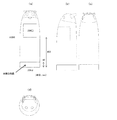
図27は、運搬ロボット1002の寸法の一例を示す図である。図27(a)〜(d)は、それぞれ、正面図、左側面図、背面図、上面図である。図27(b)、(d)における破線は収納領域の位置を示している。この例では、宅内で邪魔にならないように、底面の直径が30cmに設定されている。高さは、ユーザが座っている時に、物の受け渡しがしやすく、インタラクションもしやすくなるように設定されている。収納領域の下部の高さは45cm、全体の高さは85cmに設定されている。筐体の下部には、車輪を内蔵する部分(高さ8cm)が設けられている。収納領域を正面から見たときの形状は、20cm角である。これらの寸法は一例であり、寸法はこの例に限定されない。
FIG. 27 is a diagram illustrating an example of dimensions of the
図28は、運搬ロボット1002のデザインの他の例を示す図である。この例のように、運搬ロボット1002に丸みを帯びさせることで親近感を抱かせるようにしたデザインも可能である。図28の設計例では、運搬ロボット1002を横からみた場合に、運搬物を格納する部分(格納部)の上辺の長さに対する下辺の長さの比率が、図28の例のそれよりも大きい。このような設計により、ユーザが格納部よりも高い位置から格納部内を覗いたときに、中に入っている物を見やすい。格納部よりも高い位置から格納部内に入っているものを取り出すことも容易である。ここで、棚ロボット1001が、棚ロボット1001内に格納されている物品を運搬ロボット1002に受け渡す場合に、物品そのものを受け渡す場合が想定される。一方で、棚ロボット1001内の各棚に物品の入った箱を格納していて、物品の入ったその箱を運搬ロボット1002に渡す場合も想定される。特に物品の入った箱を運搬ロボット1002に受け渡す場合において、図28のように運搬物を格納する部分の上辺の長さに対する下辺の長さの比率が大きいことにより、物品の入った箱を棚ロボット1001から運搬ロボット1002へ受け渡し易くなる。
FIG. 28 is a diagram illustrating another example of the design of the
図29は、物品受け渡し時の運搬ロボット1002の位置決めを専用のセンサを用いて行う場合の構成例を示す図である。この例における棚ロボット1001は、受け渡し口1003の近傍に赤外線を発する発信器1401を備えている。発信器1401が発生した赤外線を運搬ロボット1002に搭載されたセンサがとらえることで、精度の良い位置決めを行いやすい。
FIG. 29 is a diagram illustrating a configuration example in the case of positioning the
本開示のシステムによれば、ユーザの指示に従って、運搬ロボットが棚ロボットに物を運んだり、棚ロボットからユーザに物を運んだりすることができるため、ユーザの宅内生活の利便性が増す。 According to the system of this indication, according to a user's directions, since a conveyance robot can carry a thing to a shelf robot or a thing from a shelf robot to a user, the convenience of a user's home life increases.
1001 棚ロボット
1002 運搬ロボット
1003 受け渡し口
1004 物品移動装置
1005 レール
1006 ユーザ
1008 棚
1010 ベルト機構
1011 トレイ
1022 入力インターフェース
1024 第1制御回路
1025 記録媒体
1026 第1通信回路
1028 移動機構
1044 第2制御回路
1045 記録媒体
1046 第2通信回路
1048 コンベヤー機構
1100 距離画像センサ
1101 ユーザ位置推定部
1102 要求受付部
1103 要求履歴DB
1105 移動制御部
1106 移動時間比較判定部
1107 自己位置推定部
1108 ユーザ行動推定部
1109 移動経路算出部
1110 宅内マップDB
1120 スピーカー
1202 駆動制御部
1204 吐出時間算出部
1205 吐出時間比較判定部
1206 保管場所管理部
1207 保管物情報DB
1300 環境側センサ
1301 制御回路
1302 通信回路
1303 距離画像センサ
1304 ユーザ位置推定部
1305 ユーザ状態推定部
1401 発信器
1001
DESCRIPTION OF
DESCRIPTION OF
DESCRIPTION OF
Claims (15)
物を保管する棚ロボットと、
を備える物管理システムであって、
前記運搬ロボットは、
ユーザから渡された物を前記棚ロボットまで運搬する要求、および、前記棚ロボットに保管されている物を前記ユーザまで運搬する要求の少なくとも一方を含む運搬要求を、前記ユーザから受け付ける入力インターフェースと、
前記入力インターフェースが前記運搬要求を受け付けた後、前記運搬要求に基づく通知を前記棚ロボットに送信する第1通信回路と、
前記第1通信回路が前記通知を送信した後、前記運搬ロボットを前記棚ロボットまで移動させる移動機構と、
を有し、
前記棚ロボットは、
前記第1通信回路から送信された前記通知を受信する第2通信回路と、
前記第2通信回路が前記通知を受信した後、前記運搬要求に係る物を、前記物の保管位置から前記運搬ロボットとの受け渡し位置まで移動させる、または、前記運搬ロボットから前記運搬要求に係る物を受け取って所定の保管位置に移動させるコンベヤー機構と、
を有する、
物管理システム。 A transport robot that transports things,
A shelf robot to store things,
An object management system comprising:
The transport robot is
An input interface that accepts from the user a transportation request including at least one of a request to transport an object delivered from a user to the shelf robot and a request to transport an object stored in the shelf robot to the user;
A first communication circuit for transmitting a notification based on the transport request to the shelf robot after the input interface has received the transport request;
A movement mechanism for moving the transport robot to the shelf robot after the first communication circuit transmits the notification;
Have
The shelf robot is
A second communication circuit for receiving the notification transmitted from the first communication circuit;
After the second communication circuit receives the notification, the object related to the transport request is moved from the storage position of the object to the delivery position with the transport robot, or the object related to the transport request from the transport robot. A conveyor mechanism for receiving and moving to a predetermined storage position;
Having
Material management system.
前記棚ロボットは、前記第2通信回路および前記コンベヤー機構を制御する第2制御回路をさらに有し、
前記運搬要求が、前記棚ロボットに保管されている物を前記ユーザまで運搬する要求を含むとき、
前記1制御回路は、
前記第1通信回路に前記通知を送信させ、
前記運搬ロボットが前記棚ロボットまで移動し、前記運搬要求に係る物が前記棚ロボットから前記運搬ロボットに渡された後、前記運搬ロボットが前記ユーザまで移動するように、前記移動機構を制御し、
前記第2制御回路は、前記第2通信回路が前記通知を受信した後、前記運搬要求に係る前記物を、前記保管位置から前記受け渡し位置まで移動させるように、前記コンベヤー機構を制御する、
請求項1に記載の物管理システム。 The transport robot further includes a first control circuit that controls the first communication circuit and the moving mechanism,
The shelf robot further includes a second control circuit for controlling the second communication circuit and the conveyor mechanism,
When the transport request includes a request to transport an object stored in the shelf robot to the user,
The one control circuit includes:
Causing the first communication circuit to transmit the notification;
The transport robot moves to the shelf robot, and after the object related to the transport request is passed from the shelf robot to the transport robot, the transport robot is controlled to move to the user,
The second control circuit controls the conveyor mechanism to move the object related to the transport request from the storage position to the delivery position after the second communication circuit receives the notification.
The object management system according to claim 1.
前記第2制御回路は、前記第2通信回路が前記通知を受信してから前記運搬要求に係る物を前記受け渡し位置に移動させるまでに要する受け渡し時間を算出し、前記受け渡し時間を示す情報を前記第2通信回路に送信させ、
前記第1制御回路は、前記第1通信回路が前記受け渡し時間を示す前記情報を前記第2通信回路から受け取った後、前記移動時間と前記受け渡し時間とを比較し、前記移動時間が前記受け渡し時間よりも短いとき、前記移動時間と前記受け渡し時間との差分に応じた時間だけ、前記棚ロボットへの移動の開始を遅らせるように、前記移動機構を制御する、
請求項2に記載の物管理システム。 The first control circuit calculates a movement route and a movement time to the shelf robot,
The second control circuit calculates a delivery time required from the time when the second communication circuit receives the notification until the object related to the transport request is moved to the delivery position, and information indicating the delivery time is obtained. To the second communication circuit,
The first control circuit compares the movement time with the delivery time after the first communication circuit receives the information indicating the delivery time from the second communication circuit, and the movement time is the delivery time. The movement mechanism is controlled so as to delay the start of movement to the shelf robot by a time corresponding to the difference between the movement time and the delivery time.
The object management system according to claim 2.
前記第2制御回路は、前記第2通信回路が前記移動時間を示す前記情報を受信した後、前記移動時間と前記受け渡し時間とを比較し、前記受け渡し時間が前記移動時間よりも短いとき、前記移動時間と前記受け渡し時間との差分に応じた時間だけ、前記物の移動の開始を遅らせるように、前記コンベヤー機構を制御する、
請求項3に記載の物管理システム。 The first control circuit causes the first communication circuit to transmit information indicating the travel time;
After the second communication circuit receives the information indicating the travel time, the second control circuit compares the travel time with the delivery time, and when the delivery time is shorter than the travel time, Controlling the conveyor mechanism to delay the start of movement of the object by a time corresponding to the difference between the movement time and the delivery time;
The object management system according to claim 3.
前記第2制御回路は、前記運搬要求に係る物が、前記棚に収納されているとき、前記物の加工に要する時間を含めて、前記受け渡し時間を算出する、
請求項3または4に記載の物管理システム。 The shelf robot has at least one shelf having a function of processing stored items,
The second control circuit calculates the delivery time including the time required for processing the object when the object related to the transport request is stored in the shelf.
The object management system according to claim 3 or 4.
前記第2通信回路は、前記第2通信回路が前記物に関する情報を受信したとき、前記物を、前記保管位置から前記受け渡し位置により近い位置に予め移動させておくように、前記コンベヤー機構を制御する、
請求項2から6のいずれかに記載の物管理システム。 Before the input interface accepts the transportation request, the first control circuit includes detection information output from a sensor that detects the state of the user, an object related to a past transportation request, and a user state at the time of the request. On the basis of the history information recording the correspondence relationship, and predicting an object that is required to be transported, causing the first communication circuit to transmit information about the predicted object,
The second communication circuit controls the conveyor mechanism so that when the second communication circuit receives information about the object, the object is moved in advance from the storage position to a position closer to the delivery position. To
The object management system according to any one of claims 2 to 6.
前記コンベヤー機構は、前記複数の棚に保管されている物のうち、前記運搬要求の頻度が所定の頻度よりも低い物を、前記配送用の棚に移動させ、
前記第2通信回路は、前記物について、前記運搬業者のサーバに、外部倉庫への配送要求を送信する、
請求項1から10のいずれかに記載の物管理システム。 The shelf robot has a plurality of shelves including a delivery shelf having a structure that allows a carrier to take in and out of goods,
The conveyor mechanism moves, among the items stored on the plurality of shelves, a product whose frequency of the transportation request is lower than a predetermined frequency to the delivery shelf,
The second communication circuit transmits a delivery request to an external warehouse to the server of the carrier for the object.
The thing management system in any one of Claim 1 to 10.
前記第2制御回路は、前記物に関連付けられた所定の条件を満たす場合にのみ、前記物を前記運搬ロボットに渡すように前記コンベヤー機構を制御する、
請求項2から11のいずれかに記載の物管理システム。 When the transport request includes a request to transport an object stored in the shelf robot to the user,
The second control circuit controls the conveyor mechanism so as to pass the object to the transport robot only when a predetermined condition associated with the object is satisfied.
The thing management system according to any one of claims 2 to 11.
前記第2制御回路は、前記人の承認を得るために、前記人が有する情報装置に、前記運搬要求を許可するか否かを問い合わせ、前記問い合わせを行っている間、前記運搬ロボットに待機するように指示する、
請求項12に記載の物管理システム。 The predetermined condition is obtaining approval of a specific person other than the user,
The second control circuit inquires of the information device that the person has whether to permit the transportation request, and waits for the transportation robot while making the inquiry, in order to obtain the person's approval. To instruct
The object management system according to claim 12.
前記運搬ロボットとの間で前記物の受け渡しを行うための受け渡し口と、
物を保管するための複数の棚と、
を有し、
前記コンベヤー機構は、前記複数の棚の1つと前記受け渡し口との間で前記物を移動させる、
請求項1から13のいずれかに記載の物管理システム。 The shelf robot is
A delivery port for delivering the object to and from the transport robot;
Multiple shelves to store things,
Have
The conveyor mechanism moves the object between one of the plurality of shelves and the delivery port;
The thing management system in any one of Claim 1 to 13.
前記棚ロボットに保管されている物を前記ユーザまで運搬する要求を含む運搬要求を、前記ユーザから受け付ける入力インターフェースと、
前記入力インターフェースが前記運搬要求を受け付けた後、前記運搬要求に基づく通知を前記棚ロボットに送信し、前記棚ロボットが前記通知を受信してから前記運搬要求に係る物を前記運搬ロボットとの受け渡し位置に移動させるまでに要する受け渡し時間を示す情報を受信する通信回路と、
前記通信回路が前記通知を送信した後、前記運搬ロボットを前記棚ロボットまで移動させる移動機構と、
前記通信回路および前記移動機構を制御する制御回路であって、前記棚ロボットまでの移動経路および移動時間を算出し、前記移動時間と前記受け渡し時間とを比較し、前記移動時間が前記受け渡し時間よりも短いとき、前記移動時間と前記受け渡し時間との差分に応じた時間だけ、前記棚ロボットへの移動の開始を遅らせるように、前記移動機構を制御する制御回路と、
を備える運搬ロボット。
A transport robot used in an object management system comprising a transport robot for transporting an object and a shelf robot for storing the object,
An input interface that receives from the user a transport request including a request to transport an object stored in the shelf robot to the user;
After the input interface accepts the transportation request, a notification based on the transportation request is transmitted to the shelf robot, and after the shelf robot receives the notification, an object related to the transportation request is delivered to the transportation robot. A communication circuit that receives information indicating a delivery time required to move to a position;
A movement mechanism for moving the transport robot to the shelf robot after the communication circuit transmits the notification;
A control circuit for controlling the communication circuit and the movement mechanism, calculating a movement route and a movement time to the shelf robot, comparing the movement time and the delivery time, and comparing the movement time with the delivery time. A control circuit that controls the moving mechanism so as to delay the start of movement to the shelf robot by a time according to the difference between the moving time and the delivery time,
A transport robot comprising:
Priority Applications (2)
| Application Number | Priority Date | Filing Date | Title |
|---|---|---|---|
| US14/660,069 US9643779B2 (en) | 2014-03-31 | 2015-03-17 | Article management system and transport robot |
| US15/472,963 US9926136B2 (en) | 2014-03-31 | 2017-03-29 | Article management system and transport robot |
Applications Claiming Priority (2)
| Application Number | Priority Date | Filing Date | Title |
|---|---|---|---|
| US201461972537P | 2014-03-31 | 2014-03-31 | |
| US61/972,537 | 2014-03-31 |
Publications (2)
| Publication Number | Publication Date |
|---|---|
| JP2015196600A true JP2015196600A (en) | 2015-11-09 |
| JP6416590B2 JP6416590B2 (en) | 2018-10-31 |
Family
ID=54546546
Family Applications (1)
| Application Number | Title | Priority Date | Filing Date |
|---|---|---|---|
| JP2014225432A Expired - Fee Related JP6416590B2 (en) | 2014-03-31 | 2014-11-05 | Material management system and transport robot |
Country Status (1)
| Country | Link |
|---|---|
| JP (1) | JP6416590B2 (en) |
Cited By (25)
| Publication number | Priority date | Publication date | Assignee | Title |
|---|---|---|---|---|
| KR20180014515A (en) * | 2016-08-01 | 2018-02-09 | 삼성전자주식회사 | A robotic cleaner, a refrigerator, a system of delivery of a container and a method of delivering and retrieving of a container of the refrigerator using the robotic cleaner |
| WO2018155063A1 (en) * | 2017-02-22 | 2018-08-30 | パナソニックIpマネジメント株式会社 | Storage management system, storage management method and program |
| WO2018155060A1 (en) * | 2017-02-22 | 2018-08-30 | パナソニックIpマネジメント株式会社 | Storage management system, storage management method and program |
| WO2018155064A1 (en) * | 2017-02-22 | 2018-08-30 | パナソニックIpマネジメント株式会社 | Storage management system, storage management method and program |
| WO2018155062A1 (en) * | 2017-02-22 | 2018-08-30 | パナソニックIpマネジメント株式会社 | Housing management system, housing management method, and program |
| JP2018190379A (en) * | 2017-05-01 | 2018-11-29 | サビオーク インコーポレイテッドSavioke, Inc. | System and method for robotic delivery between moving targets |
| JP2019011971A (en) * | 2017-06-29 | 2019-01-24 | 株式会社東芝 | Estimation system and automobile |
| CN109335669A (en) * | 2018-12-19 | 2019-02-15 | 攀枝花学院 | A control circuit of a handling robot |
| KR20190103105A (en) * | 2019-07-12 | 2019-09-04 | 엘지전자 주식회사 | Robot and method for managing goods using same |
| KR20200031661A (en) * | 2017-11-14 | 2020-03-24 | 하이 로보틱스 씨오., 엘티디. | Transport robot and pickup method based on transport robot |
| WO2020071296A1 (en) * | 2018-10-05 | 2020-04-09 | ソニー株式会社 | Control device, control method, and program |
| JP2020121887A (en) * | 2019-01-14 | 2020-08-13 | 株式会社Mujin | Robot system control device and control method |
| JP2020205053A (en) * | 2019-06-11 | 2020-12-24 | Tradfit株式会社 | Program, method for processing information, and image processor |
| CN112829851A (en) * | 2019-11-25 | 2021-05-25 | 丰田自动车株式会社 | Delivery system, delivery method and procedure |
| WO2021171989A1 (en) * | 2020-02-28 | 2021-09-02 | オムロン株式会社 | Transport system and transport robot |
| JP2022040134A (en) * | 2017-06-29 | 2022-03-10 | 株式会社東芝 | Estimation system and automobile |
| CN114194690A (en) * | 2021-12-29 | 2022-03-18 | 杭州海康机器人技术有限公司 | Material handling method, device, equipment, storage medium and system |
| KR20220047715A (en) * | 2020-10-10 | 2022-04-19 | 하이 로보틱스 씨오., 엘티디. | Warehousing system, material handling method, control terminal, robot, and storage medium |
| WO2022145081A1 (en) * | 2020-12-28 | 2022-07-07 | パナソニックIpマネジメント株式会社 | Transport system, transport method, route information creation system, and route information creation method |
| CN114852573A (en) * | 2022-05-12 | 2022-08-05 | 拉扎斯网络科技(上海)有限公司 | Conveying device, cabinet and conveying equipment |
| JP2022186129A (en) * | 2021-06-04 | 2022-12-15 | トヨタ自動車株式会社 | Mobile body system |
| WO2023063483A1 (en) * | 2021-10-13 | 2023-04-20 | (주)필드로 | Robotic article storage and delivery integrated automation system |
| WO2023124805A1 (en) * | 2021-12-30 | 2023-07-06 | 杭州海康机器人股份有限公司 | Collaborative carrying processing method and apparatus, electronic device, and system |
| CN119175706A (en) * | 2024-09-12 | 2024-12-24 | 杭州海康机器人股份有限公司 | Robot scheduling system, method and storage medium |
| US20250248676A1 (en) * | 2023-03-23 | 2025-08-07 | Siemens Healthineers Ag | Measuring system and method |
Citations (4)
| Publication number | Priority date | Publication date | Assignee | Title |
|---|---|---|---|---|
| JP2004231357A (en) * | 2003-01-30 | 2004-08-19 | Matsushita Electric Ind Co Ltd | Robot system |
| JP2007156577A (en) * | 2005-11-30 | 2007-06-21 | Mitsubishi Heavy Ind Ltd | Method of gaining color information using life support robot |
| JP2007152443A (en) * | 2005-11-30 | 2007-06-21 | Mitsubishi Heavy Ind Ltd | Clearing-away robot |
| JP2011189481A (en) * | 2010-03-16 | 2011-09-29 | Sony Corp | Control apparatus, control method and program |
-
2014
- 2014-11-05 JP JP2014225432A patent/JP6416590B2/en not_active Expired - Fee Related
Patent Citations (4)
| Publication number | Priority date | Publication date | Assignee | Title |
|---|---|---|---|---|
| JP2004231357A (en) * | 2003-01-30 | 2004-08-19 | Matsushita Electric Ind Co Ltd | Robot system |
| JP2007156577A (en) * | 2005-11-30 | 2007-06-21 | Mitsubishi Heavy Ind Ltd | Method of gaining color information using life support robot |
| JP2007152443A (en) * | 2005-11-30 | 2007-06-21 | Mitsubishi Heavy Ind Ltd | Clearing-away robot |
| JP2011189481A (en) * | 2010-03-16 | 2011-09-29 | Sony Corp | Control apparatus, control method and program |
Cited By (45)
| Publication number | Priority date | Publication date | Assignee | Title |
|---|---|---|---|---|
| KR102565501B1 (en) * | 2016-08-01 | 2023-08-11 | 삼성전자주식회사 | A robotic cleaner, a refrigerator, a system of delivery of a container and a method of delivering and retrieving of a container of the refrigerator using the robotic cleaner |
| KR20180014515A (en) * | 2016-08-01 | 2018-02-09 | 삼성전자주식회사 | A robotic cleaner, a refrigerator, a system of delivery of a container and a method of delivering and retrieving of a container of the refrigerator using the robotic cleaner |
| JPWO2018155060A1 (en) * | 2017-02-22 | 2019-11-07 | パナソニックIpマネジメント株式会社 | Storage management system, storage management method and program |
| WO2018155064A1 (en) * | 2017-02-22 | 2018-08-30 | パナソニックIpマネジメント株式会社 | Storage management system, storage management method and program |
| WO2018155062A1 (en) * | 2017-02-22 | 2018-08-30 | パナソニックIpマネジメント株式会社 | Housing management system, housing management method, and program |
| WO2018155060A1 (en) * | 2017-02-22 | 2018-08-30 | パナソニックIpマネジメント株式会社 | Storage management system, storage management method and program |
| WO2018155063A1 (en) * | 2017-02-22 | 2018-08-30 | パナソニックIpマネジメント株式会社 | Storage management system, storage management method and program |
| JP2018190379A (en) * | 2017-05-01 | 2018-11-29 | サビオーク インコーポレイテッドSavioke, Inc. | System and method for robotic delivery between moving targets |
| JP2019011971A (en) * | 2017-06-29 | 2019-01-24 | 株式会社東芝 | Estimation system and automobile |
| US11019322B2 (en) | 2017-06-29 | 2021-05-25 | Kabushiki Kaisha Toshiba | Estimation system and automobile |
| JP7242822B2 (en) | 2017-06-29 | 2023-03-20 | 株式会社東芝 | Estimation system and car |
| JP2022040134A (en) * | 2017-06-29 | 2022-03-10 | 株式会社東芝 | Estimation system and automobile |
| KR20200031661A (en) * | 2017-11-14 | 2020-03-24 | 하이 로보틱스 씨오., 엘티디. | Transport robot and pickup method based on transport robot |
| KR102332706B1 (en) | 2017-11-14 | 2021-12-01 | 하이 로보틱스 씨오., 엘티디. | Transport robots and pickup methods based on transport robots |
| JP7306406B2 (en) | 2018-10-05 | 2023-07-11 | ソニーグループ株式会社 | Control device, control method and program |
| WO2020071296A1 (en) * | 2018-10-05 | 2020-04-09 | ソニー株式会社 | Control device, control method, and program |
| JPWO2020071296A1 (en) * | 2018-10-05 | 2021-09-02 | ソニーグループ株式会社 | Control devices, control methods and programs |
| CN109335669A (en) * | 2018-12-19 | 2019-02-15 | 攀枝花学院 | A control circuit of a handling robot |
| JP7818761B2 (en) | 2019-01-14 | 2026-02-24 | 株式会社Mujin | Control device and control method for robot system |
| JP2020121887A (en) * | 2019-01-14 | 2020-08-13 | 株式会社Mujin | Robot system control device and control method |
| US11905116B2 (en) | 2019-01-14 | 2024-02-20 | Mujin, Inc. | Controller and control method for robot system |
| JP2020205053A (en) * | 2019-06-11 | 2020-12-24 | Tradfit株式会社 | Program, method for processing information, and image processor |
| KR20190103105A (en) * | 2019-07-12 | 2019-09-04 | 엘지전자 주식회사 | Robot and method for managing goods using same |
| WO2021010502A1 (en) * | 2019-07-12 | 2021-01-21 | 엘지전자 주식회사 | Robot and method for managing article by using same |
| KR102841765B1 (en) * | 2019-07-12 | 2025-08-05 | 엘지전자 주식회사 | Robot and method for managing goods using same |
| CN112829851A (en) * | 2019-11-25 | 2021-05-25 | 丰田自动车株式会社 | Delivery system, delivery method and procedure |
| JP2021133488A (en) * | 2020-02-28 | 2021-09-13 | オムロン株式会社 | Carrier system and carrier robot |
| US12378076B2 (en) | 2020-02-28 | 2025-08-05 | Omron Corporation | Transport system and transport robot |
| JP7380330B2 (en) | 2020-02-28 | 2023-11-15 | オムロン株式会社 | Transport system and transport robot |
| CN114901436A (en) * | 2020-02-28 | 2022-08-12 | 欧姆龙株式会社 | Transfer system and transfer robot |
| WO2021171989A1 (en) * | 2020-02-28 | 2021-09-02 | オムロン株式会社 | Transport system and transport robot |
| KR102392008B1 (en) | 2020-10-10 | 2022-04-29 | 하이 로보틱스 씨오., 엘티디. | Warehousing system, material handling method, control terminal, robot, and storage medium |
| KR20220047715A (en) * | 2020-10-10 | 2022-04-19 | 하이 로보틱스 씨오., 엘티디. | Warehousing system, material handling method, control terminal, robot, and storage medium |
| JP7752362B2 (en) | 2020-12-28 | 2025-10-10 | パナソニックIpマネジメント株式会社 | Transport system, transport method, route information creation system and route information creation method |
| JPWO2022145081A1 (en) * | 2020-12-28 | 2022-07-07 | ||
| WO2022145081A1 (en) * | 2020-12-28 | 2022-07-07 | パナソニックIpマネジメント株式会社 | Transport system, transport method, route information creation system, and route information creation method |
| JP2022186129A (en) * | 2021-06-04 | 2022-12-15 | トヨタ自動車株式会社 | Mobile body system |
| JP7647346B2 (en) | 2021-06-04 | 2025-03-18 | トヨタ自動車株式会社 | Mobile Systems |
| WO2023063483A1 (en) * | 2021-10-13 | 2023-04-20 | (주)필드로 | Robotic article storage and delivery integrated automation system |
| CN114194690A (en) * | 2021-12-29 | 2022-03-18 | 杭州海康机器人技术有限公司 | Material handling method, device, equipment, storage medium and system |
| CN114194690B (en) * | 2021-12-29 | 2023-12-29 | 杭州海康机器人股份有限公司 | Material handling method, apparatus, device, storage medium and system |
| WO2023124805A1 (en) * | 2021-12-30 | 2023-07-06 | 杭州海康机器人股份有限公司 | Collaborative carrying processing method and apparatus, electronic device, and system |
| CN114852573A (en) * | 2022-05-12 | 2022-08-05 | 拉扎斯网络科技(上海)有限公司 | Conveying device, cabinet and conveying equipment |
| US20250248676A1 (en) * | 2023-03-23 | 2025-08-07 | Siemens Healthineers Ag | Measuring system and method |
| CN119175706A (en) * | 2024-09-12 | 2024-12-24 | 杭州海康机器人股份有限公司 | Robot scheduling system, method and storage medium |
Also Published As
| Publication number | Publication date |
|---|---|
| JP6416590B2 (en) | 2018-10-31 |
Similar Documents
| Publication | Publication Date | Title |
|---|---|---|
| JP6416590B2 (en) | Material management system and transport robot | |
| US9926136B2 (en) | Article management system and transport robot | |
| US11775983B2 (en) | Method and system of providing service by controlling robot in service area, and robot implementing thereof | |
| US10815104B2 (en) | Recharging apparatus and method | |
| KR102841765B1 (en) | Robot and method for managing goods using same | |
| JP7115482B2 (en) | Control system and control method | |
| US11099562B1 (en) | Autonomous delivery device | |
| US20230023807A1 (en) | System and method for item delivery by a mobile robot | |
| WO2019128048A1 (en) | Information processing method and apparatus, electronic device, and storage medium | |
| CN104769962B (en) | Environmental management system including mobile robot and method of using the same | |
| US9881276B2 (en) | Ultrasonic bracelet and receiver for detecting position in 2D plane | |
| JP6904246B2 (en) | Mobile system and control method of mobile system | |
| KR102907422B1 (en) | Robot | |
| JP2022523506A (en) | Return box guidance in warehouse order fulfillment operation | |
| JP2022523318A (en) | Optimized return box recommendation process in warehouse order fulfillment operation | |
| JP2019061325A (en) | Self-propelled service provision device and service provision system | |
| KR20180038669A (en) | Airport robot and airport robot system | |
| US20240119411A1 (en) | Order fulfillment using single order pickers and multi-order pickers | |
| US20210064019A1 (en) | Robot | |
| KR20190106909A (en) | Ai moving robot and the control mothod thereof | |
| JP2018147359A (en) | Service providing system and request reception robot | |
| JP2020135500A (en) | Vehicle dispatch system | |
| CN115610928B (en) | Delivery system, delivery method, and computer-readable program storage medium | |
| KR102376299B1 (en) | Moving robot ha and method thereof | |
| JP2020119006A (en) | System, information processing apparatus, information processing method and program |
Legal Events
| Date | Code | Title | Description |
|---|---|---|---|
| A621 | Written request for application examination |
Free format text: JAPANESE INTERMEDIATE CODE: A621 Effective date: 20170529 |
|
| A131 | Notification of reasons for refusal |
Free format text: JAPANESE INTERMEDIATE CODE: A131 Effective date: 20180619 |
|
| A521 | Request for written amendment filed |
Free format text: JAPANESE INTERMEDIATE CODE: A523 Effective date: 20180806 |
|
| TRDD | Decision of grant or rejection written | ||
| A01 | Written decision to grant a patent or to grant a registration (utility model) |
Free format text: JAPANESE INTERMEDIATE CODE: A01 Effective date: 20181002 |
|
| A61 | First payment of annual fees (during grant procedure) |
Free format text: JAPANESE INTERMEDIATE CODE: A61 Effective date: 20181004 |
|
| R150 | Certificate of patent or registration of utility model |
Ref document number: 6416590 Country of ref document: JP Free format text: JAPANESE INTERMEDIATE CODE: R150 |
|
| LAPS | Cancellation because of no payment of annual fees |