JP2015222425A - Cascaded optical harmonic generation - Google Patents
Cascaded optical harmonic generation Download PDFInfo
- Publication number
- JP2015222425A JP2015222425A JP2015103687A JP2015103687A JP2015222425A JP 2015222425 A JP2015222425 A JP 2015222425A JP 2015103687 A JP2015103687 A JP 2015103687A JP 2015103687 A JP2015103687 A JP 2015103687A JP 2015222425 A JP2015222425 A JP 2015222425A
- Authority
- JP
- Japan
- Prior art keywords
- harmonic
- light beam
- generator
- order harmonic
- crystal
- Prior art date
- Legal status (The legal status is an assumption and is not a legal conclusion. Google has not performed a legal analysis and makes no representation as to the accuracy of the status listed.)
- Granted
Links
Images


Classifications
-
- G—PHYSICS
- G02—OPTICS
- G02F—OPTICAL DEVICES OR ARRANGEMENTS FOR THE CONTROL OF LIGHT BY MODIFICATION OF THE OPTICAL PROPERTIES OF THE MEDIA OF THE ELEMENTS INVOLVED THEREIN; NON-LINEAR OPTICS; FREQUENCY-CHANGING OF LIGHT; OPTICAL LOGIC ELEMENTS; OPTICAL ANALOGUE/DIGITAL CONVERTERS
- G02F1/00—Devices or arrangements for the control of the intensity, colour, phase, polarisation or direction of light arriving from an independent light source, e.g. switching, gating or modulating; Non-linear optics
- G02F1/35—Non-linear optics
- G02F1/353—Frequency conversion, i.e. wherein a light beam is generated with frequency components different from those of the incident light beams
-
- G—PHYSICS
- G02—OPTICS
- G02F—OPTICAL DEVICES OR ARRANGEMENTS FOR THE CONTROL OF LIGHT BY MODIFICATION OF THE OPTICAL PROPERTIES OF THE MEDIA OF THE ELEMENTS INVOLVED THEREIN; NON-LINEAR OPTICS; FREQUENCY-CHANGING OF LIGHT; OPTICAL LOGIC ELEMENTS; OPTICAL ANALOGUE/DIGITAL CONVERTERS
- G02F1/00—Devices or arrangements for the control of the intensity, colour, phase, polarisation or direction of light arriving from an independent light source, e.g. switching, gating or modulating; Non-linear optics
- G02F1/35—Non-linear optics
- G02F1/355—Non-linear optics characterised by the materials used
- G02F1/3551—Crystals
-
- G—PHYSICS
- G02—OPTICS
- G02F—OPTICAL DEVICES OR ARRANGEMENTS FOR THE CONTROL OF LIGHT BY MODIFICATION OF THE OPTICAL PROPERTIES OF THE MEDIA OF THE ELEMENTS INVOLVED THEREIN; NON-LINEAR OPTICS; FREQUENCY-CHANGING OF LIGHT; OPTICAL LOGIC ELEMENTS; OPTICAL ANALOGUE/DIGITAL CONVERTERS
- G02F1/00—Devices or arrangements for the control of the intensity, colour, phase, polarisation or direction of light arriving from an independent light source, e.g. switching, gating or modulating; Non-linear optics
- G02F1/35—Non-linear optics
- G02F1/37—Non-linear optics for second-harmonic generation
-
- H—ELECTRICITY
- H01—ELECTRIC ELEMENTS
- H01S—DEVICES USING THE PROCESS OF LIGHT AMPLIFICATION BY STIMULATED EMISSION OF RADIATION [LASER] TO AMPLIFY OR GENERATE LIGHT; DEVICES USING STIMULATED EMISSION OF ELECTROMAGNETIC RADIATION IN WAVE RANGES OTHER THAN OPTICAL
- H01S3/00—Lasers, i.e. devices using stimulated emission of electromagnetic radiation in the infrared, visible or ultraviolet wave range
- H01S3/005—Optical devices external to the laser cavity, specially adapted for lasers, e.g. for homogenisation of the beam or for manipulating laser pulses, e.g. pulse shaping
- H01S3/0092—Nonlinear frequency conversion, e.g. second harmonic generation [SHG] or sum- or difference-frequency generation outside the laser cavity
-
- H—ELECTRICITY
- H01—ELECTRIC ELEMENTS
- H01S—DEVICES USING THE PROCESS OF LIGHT AMPLIFICATION BY STIMULATED EMISSION OF RADIATION [LASER] TO AMPLIFY OR GENERATE LIGHT; DEVICES USING STIMULATED EMISSION OF ELECTROMAGNETIC RADIATION IN WAVE RANGES OTHER THAN OPTICAL
- H01S3/00—Lasers, i.e. devices using stimulated emission of electromagnetic radiation in the infrared, visible or ultraviolet wave range
- H01S3/10—Controlling the intensity, frequency, phase, polarisation or direction of the emitted radiation, e.g. switching, gating, modulating or demodulating
- H01S3/106—Controlling the intensity, frequency, phase, polarisation or direction of the emitted radiation, e.g. switching, gating, modulating or demodulating by controlling devices placed within the cavity
- H01S3/108—Controlling the intensity, frequency, phase, polarisation or direction of the emitted radiation, e.g. switching, gating, modulating or demodulating by controlling devices placed within the cavity using non-linear optical devices, e.g. exhibiting Brillouin or Raman scattering
- H01S3/109—Frequency multiplication, e.g. harmonic generation
-
- G—PHYSICS
- G02—OPTICS
- G02F—OPTICAL DEVICES OR ARRANGEMENTS FOR THE CONTROL OF LIGHT BY MODIFICATION OF THE OPTICAL PROPERTIES OF THE MEDIA OF THE ELEMENTS INVOLVED THEREIN; NON-LINEAR OPTICS; FREQUENCY-CHANGING OF LIGHT; OPTICAL LOGIC ELEMENTS; OPTICAL ANALOGUE/DIGITAL CONVERTERS
- G02F1/00—Devices or arrangements for the control of the intensity, colour, phase, polarisation or direction of light arriving from an independent light source, e.g. switching, gating or modulating; Non-linear optics
- G02F1/35—Non-linear optics
- G02F1/353—Frequency conversion, i.e. wherein a light beam is generated with frequency components different from those of the incident light beams
- G02F1/354—Third or higher harmonic generation
-
- G—PHYSICS
- G02—OPTICS
- G02F—OPTICAL DEVICES OR ARRANGEMENTS FOR THE CONTROL OF LIGHT BY MODIFICATION OF THE OPTICAL PROPERTIES OF THE MEDIA OF THE ELEMENTS INVOLVED THEREIN; NON-LINEAR OPTICS; FREQUENCY-CHANGING OF LIGHT; OPTICAL LOGIC ELEMENTS; OPTICAL ANALOGUE/DIGITAL CONVERTERS
- G02F2203/00—Function characteristic
- G02F2203/05—Function characteristic wavelength dependent
- G02F2203/055—Function characteristic wavelength dependent wavelength filtering
Landscapes
- Physics & Mathematics (AREA)
- Nonlinear Science (AREA)
- Optics & Photonics (AREA)
- Electromagnetism (AREA)
- General Physics & Mathematics (AREA)
- Engineering & Computer Science (AREA)
- Plasma & Fusion (AREA)
- Chemical & Material Sciences (AREA)
- Crystallography & Structural Chemistry (AREA)
- Optical Modulation, Optical Deflection, Nonlinear Optics, Optical Demodulation, Optical Logic Elements (AREA)
Abstract
Description
本開示は光源に関し、詳細には、カスケード光高調波発生のための装置および方法に関する。 The present disclosure relates to light sources, and in particular, to an apparatus and method for cascaded optical harmonic generation.
光高調波発生を使用して、ある波長から、より短い波長、すなわちより高い周波数にレーザ光を変換することができる。例えば、周波数倍増、または第2高調波発生を使用して、近赤外線光から可視光を得ることができ、周波数3倍増を使用して、近赤外線光から青色光、紫色光、および紫外線(UV)光を得ることができる。次いで、分光法、材料処理、光ポンピングなどのために周波数倍増光および周波数3倍増光を使用することができる。 Optical harmonic generation can be used to convert laser light from one wavelength to a shorter wavelength, ie, a higher frequency. For example, frequency doubling or second harmonic generation can be used to obtain visible light from near infrared light, and frequency doubling can be used to produce blue, violet, and ultraviolet (UV) light from near infrared light. ) Can get light. Frequency doubled and frequency tripled light can then be used for spectroscopy, material processing, optical pumping, and the like.
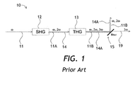
カスケード非線形光学結晶を使用して、レーザ光の光周波数を3倍にすることができる。図1を参照すると、従来技術のカスケード高調波3倍器10が一例として示されている。カスケード高調波3倍器10は、順次配設された、第2高調波結晶12(「SHG」、第2高調波発生(second harmonic generation))と、第3高調波結晶13(「THG」、第3高調波発生(third harmonic generation))と、ダイクロイック・ミラー(またはフィルタ)15とを含む。動作の際に、光周波数ωの基本光ビーム11が第2高調波結晶12に入射する。非線形変換効率は100%未満であるので、基本光ビーム11の一部だけが周波数倍増され、その結果、第2高調波周波数2ωの第2高調波ビーム14が、基本光ビーム11の未変換部分11Aと共に第2高調波結晶12から出る。第2高調波ビーム14および基本光ビーム11の未変換部分11Aが第3高調波結晶13に入射し、第3高調波結晶13は、これらのビームの一部を第3高調波周波数3ωの第3高調波ビーム19に変換する。したがって、基本光ビーム11の未変換部分11Aの未変換部分11B、第2高調波ビーム14の未変換部分14A、および第3高調波ビーム19という3つのビームが第3高調波結晶13から出る。ダイクロイック・ミラー15は、基本ビーム部分11Bおよび第2高調波ビーム部分14Aの向きを変え、第3高調波ビーム19を所望の出力として透過する。
Using cascaded nonlinear optical crystals, the optical frequency of the laser light can be tripled. Referring to FIG. 1, a prior art cascaded
従来技術のカスケード高調波3倍器10の一欠点は、妥当な変換効率を得るために、通常は基本ビーム11Aおよび第2高調波ビーム14の第3高調波結晶13への厳格な焦点合せが必要であることである。厳格な焦点合せの一欠点は、基本ビーム11Aおよび第2高調波ビーム14の小さいスポット直径が、ビーム・ウォークオフ効果のためにビーム品質を損なうことがあることである。別の欠点は、200MW/cm2範囲のUVピーク・パワー密度およびワット範囲以上の平均パワーで数十時間または数百時間照射した後で、第3高調波結晶13出力面の、UVによって誘発される劣化が生じることがあることである。Wang等により、「High Power Q-switched TEM00 Mode Diode-Pumped Solid State Lasers with > 30W Output Power at 355nm」と題する記事、Proc. SPIE Vol.6100, 610019(2006)によって指摘されているように、UVによって誘発される結晶劣化問題に対する一解決策は、結晶上の所与のスポットが劣化した後に、結晶の自動機械シフティングを使用して、結晶面の以前に使用されていないエリアにアクセスすることである。不利なことに、そのようなシステムでは、著しいコスト、複雑さ、および信頼性のリスクが増すことがある。さらに、全パルス包絡線にわたる平均化、ならびに損失および理想的でない変換条件を補償した後に、そのようなレーザは通常、30%〜40%の範囲の指定の変換効率で動作する。
One drawback of the prior art cascaded
より大きなスポット・サイズを使用することにより、変換効率が低くなることを犠牲にして、信頼性を改善することを可能にすることができる。例えば、従来技術のカスケード高調波3倍器10の基本ビーム11Aおよび第2高調波ビーム14の70マイクロメートル・スポットの代わりに、200マイクロメートル・スポットまたは350マイクロメートル・スポットを使用することにより、第3高調波結晶13のファセットでのUVパワー密度を低減することができ、その結果、第3高調波結晶13寿命が著しく改善され、結晶シフティングが不要となることがある。しかし、変換効率の低下は深刻であることがある。十分に大きなフォーカル・スポットを有するマルチワットUVレーザ・システムは、結晶シフティングを必要としないことがあるが、例えば10〜20%の範囲の低い変換効率を有することが予想され、これは、多くの商用応用例にとって低過ぎる。
By using a larger spot size, it may be possible to improve reliability at the expense of lower conversion efficiency. For example, instead of the 70 micrometer spot of the
本開示によれば、基本光ビームの光路内におけるカスケード高調波発生器の個々の高調波結晶の相対的配置を反転することができる。例えば、第3高調波発生器では、基本光ビームが、最初に第3高調波結晶に進入し、2番目に第2高調波結晶に進入することができる。基本光ビームが最初に第3高調波結晶に進入したとき、基本光は、全変換効率を向上させることのできる第2高調波発生プロセスによって消耗せず、それによってより大きなビーム・サイズで高調波発生器を操作することが可能となり、それによって信頼性が改善される。 According to the present disclosure, the relative arrangement of the individual harmonic crystals of the cascade harmonic generator in the optical path of the fundamental light beam can be reversed. For example, in a third harmonic generator, the fundamental light beam can first enter the third harmonic crystal and secondly enter the second harmonic crystal. When the fundamental light beam first enters the third harmonic crystal, the fundamental light is not consumed by the second harmonic generation process, which can improve the overall conversion efficiency, thereby harmonics with a larger beam size. It is possible to operate the generator, thereby improving reliability.
本開示の一態様によれば、
第1の基本光ビームを第2高調波光ビームと組み合わせる第1のビーム・コンバイナと、
第1の基本光ビームおよび第2高調波光ビームから第3高調波光ビームを発生する、第1のビーム・コンバイナに結合された第3高調波結晶であって、第3高調波光ビームの発生時に、残留基本光ビームが第3高調波結晶から出る第3高調波結晶と、
残留基本光ビームと第3高調波光ビームとを分離する、第3高調波結晶に結合された第1のビーム・スプリッタと、
残留基本光ビームから第2高調波光ビームを発生し、第2高調波光ビームを第1のビーム・コンバイナに結合する、第1のビーム・スプリッタに結合された第2高調波結晶と
を備える第3高調波発生器が提供される。
According to one aspect of the present disclosure,
A first beam combiner that combines a first fundamental light beam with a second harmonic light beam;
A third harmonic crystal coupled to a first beam combiner for generating a third harmonic light beam from the first fundamental light beam and the second harmonic light beam, wherein the third harmonic light beam is generated; A third harmonic crystal from which the residual fundamental light beam emerges from the third harmonic crystal;
A first beam splitter coupled to a third harmonic crystal for separating the residual fundamental light beam and the third harmonic light beam;
A third harmonic crystal coupled to the first beam splitter for generating a second harmonic light beam from the residual fundamental light beam and coupling the second harmonic light beam to the first beam combiner; A harmonic generator is provided.
本開示によれば、上記の第3高調波発生器と、
第2の基本光ビームを、第3高調波結晶によって発生された第3高調波光ビームと組み合わせる第2のビーム・コンバイナと、
第2の基本光ビームおよび第3高調波光ビームから第4高調波光ビームを発生する、第2のビーム・コンバイナに結合された第4高調波結晶であって、第4高調波光ビームの発生時に、第1の基本光ビームが第4高調波結晶から出る第4高調波結晶と、
第1の基本光ビームと第4高調波光ビームとを分離し、第1の基本光ビームを第3高調波発生器の第1のビーム・コンバイナに結合する、第4高調波結晶に結合された第2のビーム・スプリッタと
を備える第4高調波発生器がさらに提供される。
According to the present disclosure, the third harmonic generator described above;
A second beam combiner that combines a second fundamental light beam with a third harmonic light beam generated by a third harmonic crystal;
A fourth harmonic crystal coupled to a second beam combiner for generating a fourth harmonic light beam from the second fundamental light beam and the third harmonic light beam, wherein the fourth harmonic light beam is generated; A fourth harmonic crystal from which the first fundamental light beam exits the fourth harmonic crystal;
Coupled to a fourth harmonic crystal that separates the first fundamental light beam and the fourth harmonic light beam and couples the first fundamental light beam to the first beam combiner of the third harmonic generator; A fourth harmonic generator comprising a second beam splitter is further provided.
本開示の別の態様によれば、主光ビームからカスケード光高調波を発生するカスケード高調波発生器であって、
高次高調波光ビームを発生すると共に、残留低次高調波光ビームを透過する、主光ビームの経路内に配設された高次高調波発生器と、
低次高調波光ビームを発生すると共に、残留主光ビームを透過する、高次高調波発生器の下流側の主光ビームの経路内に配設された低次高調波発生器と、
高次高調波発生器を通じて伝播する主光ビームから高次高調波光ビームを分割する、高次高調波発生器と低次高調波発生器との間の主光ビームの経路内に配設された高調波分離器と、
低次高調波発生器によって発生された低次高調波光ビームを、高調波光ビームを発生する高次高調波発生器に結合する、低次高調波発生器の下流側の残留主光ビームの経路内に配設された高調波コンバイナと
を備えるカスケード高調波発生器がさらに提供される。
According to another aspect of the present disclosure, a cascade harmonic generator for generating cascade optical harmonics from a main light beam, comprising:
A high-order harmonic generator disposed in the path of the main light beam that generates a high-order harmonic light beam and transmits the residual low-order harmonic light beam;
A low-order harmonic generator disposed in the path of the main light beam downstream of the high-order harmonic generator that generates the low-order harmonic light beam and transmits the residual main light beam;
Arranged in the path of the main light beam between the high order harmonic generator and the low order harmonic generator, which splits the high order harmonic light beam from the main light beam propagating through the high order harmonic generator A harmonic separator;
In the path of the residual main light beam downstream of the low-order harmonic generator that couples the low-order harmonic light beam generated by the low-order harmonic generator to the high-order harmonic generator that generates the harmonic light beam There is further provided a cascade harmonic generator comprising a harmonic combiner disposed in
一実施形態では、カスケード高調波発生器は、主光ビームを供給するパルス光源をさらに備え、主光ビームは、低次高調波発生器および高次高調波発生器を備える光ループ内の光ラウンド・トリップ時間のほぼ整数倍のパルス間隔でパルシングされる。 In one embodiment, the cascaded harmonic generator further comprises a pulsed light source that provides a main light beam, wherein the main light beam is an optical round in an optical loop comprising a low order harmonic generator and a high order harmonic generator. • Pulsed with a pulse interval that is approximately an integral multiple of the trip time.
本開示の別の態様によれば、主光ビームからカスケード光高調波を発生する方法であって、
低次高調波光ビームを発生するために、高次高調波発生器を通じて、次いで低次高調波発生器を通じて、主光ビームを順々に伝播するステップと、
高次高調波光ビームを発生するために、低次高調波光ビームが高次高調波発生器内で主光ビームと重複するように、高次高調波発生器を通じて、低次高調波発生器によって発生された低次高調波光ビームを伝播するステップと
を含む方法がさらに提供される。
According to another aspect of the present disclosure, a method for generating cascaded optical harmonics from a main light beam comprising:
Sequentially propagating the main light beam through a high order harmonic generator and then through a low order harmonic generator to generate a low order harmonic light beam;
Generated by the low-order harmonic generator through the high-order harmonic generator so that the low-order harmonic light beam overlaps the main light beam in the high-order harmonic generator to generate the high-order harmonic light beam Propagating the generated low-order harmonic light beam is further provided.
本開示の別の態様によれば、主光ビームからカスケード光高調波を発生する方法であって、
m=2、...、M、M≧3として、第m高調波発生器のそれぞれ1つを備える複数の高調波発生器を用意するステップと、
第M高調波発生器から開始して、第2高調波発生器で終了する、mの降順で複数の高調波発生器を通じて主光ビームを伝播するステップと、
n=2、...、M−1として、第(n+1)高調波発生器を通じて、その中で主光ビームと重複するように、各第n高調波光ビームを伝播するステップと、
第M高調波光ビームを出力するステップと
を含む方法がさらに提供される。
According to another aspect of the present disclosure, a method for generating cascaded optical harmonics from a main light beam comprising:
m = 2,. . . , M, M ≧ 3, providing a plurality of harmonic generators each having one of the mth harmonic generators;
Propagating the main light beam through the plurality of harmonic generators in descending order of m, starting with the Mth harmonic generator and ending with the second harmonic generator;
n = 2,. . . , M-1 through each nth harmonic light beam through the (n + 1) th harmonic generator so as to overlap the main light beam therein,
Outputting a Mth harmonic light beam is further provided.
例示的一実施形態では、基本光ビームまたは主光ビームが、閉光ループを形成しないように配向される。例えば、2回目に最高次高調波発生器に再進入する前に、基本光ビームまたは主光ビームを光ビーム・ダンプに配向することができる。 In an exemplary embodiment, the base light beam or the main light beam is oriented so as not to form a closed light loop. For example, the fundamental or main light beam can be directed to the light beam dump before reentering the highest harmonic generator a second time.
次に、図面と共に例示的実施形態を説明する。 Exemplary embodiments will now be described with reference to the drawings.
本教示を様々な実施形態および例と共に説明するが、本教示はそのような実施形態に限定されないものとする。それどころか、当業者は理解するであろうが、本教示は、様々な代替実施形態および均等物を包含する。 While the present teachings are described in conjunction with various embodiments and examples, it is not intended that the present teachings be limited to such embodiments. On the contrary, those skilled in the art will appreciate that the present teachings encompass various alternative embodiments and equivalents.
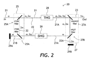
図2を参照すると、第3高調波発生器20が、第2高調波結晶(「SHG」、第2高調波発生)26、第3高調波結晶(「THG」、第3高調波発生)28、第1のビーム・コンバイナ25、および第1のビーム・スプリッタ27を含むことができる。第1のビーム・コンバイナ25は、2つのダイクロイック・ミラー25Aを含むことができる。ダイクロイック・ミラー25Aは、図2では「1T2Rフィルタ」と表されており、これは、基本(「1」)光周波数ωを透過する(「T」)こと、および2倍の(「2」)光周波数2ωを反射する(「R」)ことを都合よく象徴する。第1のビーム・スプリッタ27は、上側ダイクロイック・ミラー27Aおよび下側ダイクロイック・ミラー27Bを含むことができる。同様に、上側ダイクロイック・ミラー27Aが「1R2R3Tフィルタ」と表されており、これは、基本(「1」)光周波数ωを反射する(「R」)こと、2倍の(「2」)光周波数2ωを反射する(「R」)こと、および3倍の(「3」)光周波数3ωを透過する(「T」)ことを象徴する。下側ダイクロイック・ミラー27Bが「1R2Tフィルタ」と表されており、これは、基本(「1」)光周波数ωを反射する(「R」)こと、および2倍の(「2」)光周波数2ωを透過する(「T」)ことを象徴する。本明細書および図面の残りの部分全体にわたって、上記のミラー表記法に従う。
Referring to FIG. 2, the third
第1のビーム・コンバイナ25では、2つの同一のダイクロイック・ミラー25Aである上側および下側のダイクロイック・ミラー25Aを使用して、基本光周波数ωの第1の基本光ビーム21を2倍の光周波数2ωの第2高調波光ビーム22と組み合わせることができる。第3高調波結晶28を第1のビーム・コンバイナ25の上側ダイクロイック・ミラー25Aに結合して、基本光周波数ωの第1の基本光ビーム21および2倍の光周波数2ωの第2高調波光ビーム22から3倍の光周波数3ωの第3高調波光ビーム23を発生することができる。3倍の光周波数3ωの第3高調波光ビーム23の発生時に、基本光周波数ωの残留基本光ビーム21Aは第3高調波結晶28を出て、第1のビーム・スプリッタ27の上側フィルタ27Aを介して、第1のビーム・スプリッタ27の下側フィルタ27Bに配向することができ、さらに第2高調波結晶26を通り、第2高調波結晶26では、残留基本光ビーム21Aを使用して、第2高調波光ビーム22を発生することができる。残留基本光ビーム21Aの残留ビーム21Bが、第1のビーム・コンバイナ25の下側ダイクロイック・ミラー25Aを通り、下側ダイクロイック・ミラー25Aで、任意選択の光ビーム・ダンプ29A(図2の左下)によって残留ビーム21Bを吸収することができる。2倍の光周波数2ωの、第3高調波結晶28からの残留第2高調波ビーム22Aを上側ダイクロイック・ミラー27Aによって反射させ、下側ダイクロイック・ミラー27Bを通じて、別の任意選択の光ビーム・ダンプ29B(図2の右下)に伝播することができる。第2高調波結晶26の左に向かう第2高調波光ビーム22が、第1のビーム・コンバイナ25に結合され、本節の初めで述べたように、第1のビーム・コンバイナ25を使用して、第1の基本光ビーム21を第2高調波光ビーム22と組み合わせ、第3高調波光ビーム23を発生することができる。
In the
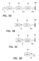
図3A〜3Cを参照することにより、基本光周波数ωの第1の基本光ビーム21、2倍の光周波数2ωの第2高調波光ビーム22、および3倍の光周波数3ωの第3高調波光ビーム23の光路をより容易に追跡することができる。図3Aでは、基本光周波数ωの第1の基本光ビーム21が、順々に、第3高調波結晶28を通じて伝播し、次いで残留基本光ビーム21Aとして第2高調波結晶26を通じて伝播し、次いで、残留基本光ビーム21Aの残留ビーム21Bとして、左側光ビーム・ダンプ29Aに配向される。図3Bでは、2倍の光周波数2ωの第2高調波光ビーム22が第2高調波結晶26で発生され、第3高調波結晶28を通じて伝播し、残留第2高調波光ビーム22Aとして右側光ビーム・ダンプ29Bに配向される。図3Cでは、第3高調波光ビーム23が第3高調波結晶28で発生され、第3高調波発生器20の出力に配向される。
3A to 3C, the first
根本的に、前述のプロセスは、少なくとも以下の理由で、図1の従来技術の周波数3倍器10よりも高い変換効率を実現することができる。第3高調波変換効率は、基本光周波数ωと2倍の光周波数2ωの入力パワー密度の積にほぼ依存する。図1の従来技術の周波数3倍器10では、第3高調波結晶13に対する全パワー入力が、第3高調波発生器に対する全パワー入力Pに限定される。第2高調波結晶12は、ωの入力パワーPの一部を2ωに変換するが、全パワーはほぼ不変のままであるからである。通常、ωのパワーが約0.4Pであり、2ωのパワーが約0.6Pであり、積が0.24P2であるとき、ωおよび2ωの3ωへの最適変換を行うことができる。図2の第3高調波発生器20では、第3高調波結晶28の入力は、ωの1.0Pと、2ωの通常は約0.6Pからなり、したがって、積は約0.6P2とすることができ、これは、従来技術の第3高調波3倍器10よりも2.5倍高い。第1にTHGプロセスで、第2にSHGプロセスで、ωのパワーの多くを2度使用することができるので、第3高調波結晶28に対する全光パワー入力は実際にはPよりも大きい。その結果、パワー密度、したがって変換効率を従来技術の第3高調波3倍器10よりもずっと高くすることができる。
Fundamentally, the process described above can achieve higher conversion efficiency than the prior
再び図3A〜3Cをしばらくの間参照すると、潜在的な光干渉効果を回避するために、例えば下側ダイクロイック・ミラー25Aを使用することにより、または何らかの他の適切なフィルタにより、残留基本光ビーム21Bが第3高調波結晶28に再進入することを防止することができる。同様に、例えば下側フィルタ27Bを使用することにより、または何らかの他の適切なフィルタにより、残留第2高調波光ビーム22Aが第2高調波結晶26に再進入することを防止することができる。言い換えれば、個々の光周波数で閉ループを形成しない(すなわち、開ループ)ように、または個々の光周波数の光共振器を形成しないように、基本光ビーム21および第2高調波光ビーム22の光路を構成することができる。個々の光周波数の閉ループまたは光共振器を避けることにより、第2および第3高調波発生プロセスの安定性を促進することができる。
Referring back to FIGS. 3A-3C for some time, the residual fundamental light beam can be avoided, for example, by using the lower
第2高調波結晶26および第3高調波結晶28は、波長、パワー・レベル、または他のパラメータに応じて、異なる材料を含むことができる。SHGおよびTHGに関する位相整合は多種多様なものでよく、タイプIまたはタイプII、臨界または非臨界、コリニア(collinear)または非コリニアでよい。例えば周期的分極材料を使用する準位相整合も選択肢でよい。ダイクロイックまたはトリクロイック薄膜フィルタ、偏光フィルタ、吸収フィルタ、プリズム、格子、または当業者に周知の他のフィルタもしくはミラーなどの様々な種類のミラーまたは光学フィルタを使用して、ビーム21、22、および23を分離し、または組み合わせることができる。フィルタ、結晶、ミラーなどの様々な順序付けおよび組合せを使用することができる。変換構成の仕様に応じて所望の偏光状態またはビーム・サイズまたはプロファイルを実現するために、適切な位置に波長板、非平面ビーム経路、またはレンズを含めることができる。表面反射によるパワー損失を低減するために、反射防止被膜またはブリュースター角表面を第2高調波結晶26および第3高調波結晶28上に実装することができる。
Second
図2の第3高調波発生器20の1つの魅力的な特徴は、基本光周波数ωの第1の基本光ビーム21および2倍の光周波数2ωの第2高調波光ビーム22が別々に第3高調波結晶28に送られるので、個々のダイクロイック・ミラー25Aの単純な調節により、特定の変換構成に対してビーム21および22の位置および角度を最適化できることである。したがって、例えば、ウォークオフ補償のために複屈折板または分散ウォークオフ板が不要となることがある。同様に、非コリニア位相整合では、基本光周波数ωの第1の基本光ビーム21と、2倍の光周波数2ωの第2高調波光ビーム22との間の所望の角度を生み出すのに、プリズムまたは他の分散素子が不要となることがある。
One attractive feature of the third
光がダイクロイック・ミラー25A、27A、および27Bによって形成されたループの周りを移動するのに必要な時間と、第2高調波結晶26および第3高調波結晶28を含むこと(図2)により、第2高調波光ビーム22は、第1の基本光ビーム21に対して、第3高調波結晶28に遅れて到達する。したがって、一般には、この構成は、光がループの周りを移動するのに必要な時間よりも持続時間が長い入力パルスを用いる動作に対して適合可能にすることができる。第2高調波結晶26および第3高調波結晶28を含む、そのようなループの典型的な最小寸法は、100ピコ秒程度の最小有効パルス持続時間に対応する、数センチメートル、例えば3cmとなる。したがって、前述の逆順高調波変換技法は、ナノ秒以上のパルスを発生するレーザ・システム、例えばQスイッチ固体レーザならびに持続波(CW)レーザにより適したものにすることができる。ミリメートル以下のサイズのマイクロ・オプティクスを使用して、例えばモード・ロック・レーザからの、ピコ秒パルスに対処するより小さいループを構築することができる。
By including the time required for the light to travel around the loop formed by the
ループ・ラウンド・トリップ時間がパルス間隔時間にほぼ等しくなるように、またはその倍数となるように選択される場合、図2の第3高調波発生器20の構成を、ループ・ラウンド・トリップ時間よりもそれぞれ短い複数のパルスと共に使用することもできる。後者のケースでは、第3高調波結晶28に対する入力は、新しいIRパルス、および以前のIRパルスから生成された第2高調波パルスを含む。例えば、CWモード・ロック・レーザが、数十MHzから1GHzまでの範囲の繰返し率で、持続時間約10ピコ秒以下のパルスを継続的に送達することができる。例えば、200MHzモード・ロック・レーザでは、第3高調波発生器20と同様の逆順第3高調波発生器が、150cm全光路長に対応するラウンド・トリップ時間5ナノ秒のループと共に、先行するパルスからのSHG光を使用して、各パルスを3倍にすることを可能にする。この構成は、変換効率の改善という、単一のより長いパルスのケースと同じ利点をもたらす。2つのパルスのみからなるパルス・バーストであっても、2つの入力パルスが1つのTHGパルスに効果的に組み合わされ、所与のピーク入力パワーに対してより高い出力ピーク・パワーを生成することができるので、利点がある。
When the loop round trip time is selected to be approximately equal to or a multiple of the pulse interval time, the configuration of the third
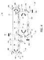
図2をさらに参照しながら次に図4を参照すると、第4高調波発生器40が、図2の第3高調波発生器20を含むことができる。ダイクロイック・ミラー45Aおよび3つの転換ミラー45Bを含む第2のビーム・コンバイナ45を設け、第2の基本光ビーム41を、第3高調波結晶28によって発生された第3高調波光ビーム23と組み合わせることができる。第4高調波結晶46(「FHG」、第4高調波発生)を第2のビーム・コンバイナ45に結合し、第2の基本光ビーム41および第3高調波光ビーム23から4倍の光周波数4ωの第4高調波光ビーム24を発生することができる。第4高調波光ビーム24の発生時に、第1の基本光ビーム21が第4高調波結晶46を出、第3高調波光ビーム23の残留ビーム23Aが第4高調波結晶46を出て、それを上側ダイクロイック・ミラー25Aまたは別の適切なスプリッタによって上部光ビーム・ダンプ49に配向することができる。本質的に、この実施形態では、第1の基本光ビーム21は、第2の基本光ビーム41の残留基本光ビームである。図2の第3高調波発生器20と同様に、第1の基本光ビーム21は、第3高調波光ビーム23および第2高調波光ビーム22を発生するために第4高調波発生器40で使用される。第2高調波スプリッタ(1T3T4Rダイクロイック・ミラー)47を第4高調波結晶46に結合して、第4高調波光ビーム24から第1の基本光ビーム21を分離し、第3高調波発生器20の第1のビーム・コンバイナ25に第1の基本光ビーム21を結合することができる。
Referring now to FIG. 4 with further reference to FIG. 2, the fourth
図5A〜5Dを参照することにより、第1の基本光ビーム21、第2の基本光ビーム41、第2高調波光ビーム22、および第3高調波光ビーム23の光路をより容易に追跡することができる。図5Aでは、第2の基本光ビーム41は第4高調波結晶46を通じて伝播する。前述のように第2の基本光ビーム41の残留基本ビームである第1の基本光ビーム21は、順々に、第3高調波結晶28を通じて伝播し、残留基本光ビーム21Aとして第2高調波結晶26を通じて伝播し、残留基本光ビーム21Aの残留ビーム21Bとして左側光ビーム・ダンプ29Aに配向することができる。図5Bでは、第2高調波光ビーム22が第2高調波結晶26で発生され、第3高調波結晶28を通じて伝播し、残留第2高調波光ビーム22Aとして右側光ビーム・ダンプ29Bに配向される。図5Cでは、第3高調波光ビーム23が第3高調波結晶28で発生され、第4高調波結晶46に配向され、次いで、残留第3高調波光ビーム23Aとして上部光ビーム・ダンプ49に配向される。最後に、図5Dでは、第4高調波ビーム24が発生され、第4高調波発生器40の出力に配向される。
By referring to FIGS. 5A to 5D, the optical paths of the first
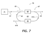
第5以上の高調波発生のために、1つまたは複数の逆順ステージを組み込む同様のカスケード構成を実装することができる。さらに図2および4を参照しながら図6を参照すると、主光ビーム61、例えば第1の基本光ビーム21(図2)または第2の基本光ビーム41(図4)からカスケード光高調波を発生するカスケード高調波発生器60(図6)が、「高次高調波光ビーム」63を発生する、主光ビーム61の経路内に配設された「高次高調波発生器」68を含むことができる。主光ビーム61の経路内、すなわち、高次高調波発生器68の下流側の残留主光ビーム61Aの経路内に「低次高調波発生器」66を配設し、残留主光ビーム61Aから「低次高調波光ビーム」62を発生することができる。「高次高調波発生器」68および「低次高調波発生器」66は、例えば、図2の第3高調波発生器20内のそれぞれ第3高調波結晶28および第2高調波結晶26でよい。別の例は、図4の第4高調波発生器40の第4高調波結晶46を「高次高調波発生器」68として含むことができ、第3高調波発生器20全体を「低次高調波発生器」66として含むことができる。
A similar cascade configuration incorporating one or more reverse order stages can be implemented for fifth or higher harmonic generation. Referring to FIG. 6 with further reference to FIGS. 2 and 4, the cascaded optical harmonics from the
高次高調波発生器68と低次高調波発生器66との間の主光ビーム61の経路内に高調波分離器67を配設し、高次高調波発生器68を通じて伝播した残留主光ビーム61Aから高次高調波光ビーム63を分割することができる。図6に示されるように、低次高調波発生器66の下流側の残留主光ビーム61Aの残留ビーム61Bの経路内に高調波コンバイナ65を配設し、低次高調波発生器66によって発生された低次高調波光ビーム62および主光ビーム61を、高調波光ビーム63を発生する高次高調波発生器68に結合すると共に、任意選択で、残留ビーム61Bを処分することができる。したがって、カスケード高調波発生器60内の主光ビーム61または低次高調波光ビーム62の経路が光閉ループにないようにビーム・コンバイナ25、45、および/または高調波スプリッタ47を構成し、正の光フィードバックによる不安定性を回避することができる。
A
図6をさらに参照しながら次に図7を参照すると、カスケード高調波発生器70が、図6のカスケード高調波発生器60と、主光ビーム61を供給するパルス光源71とを含む。図2の第3高調波発生器20のケースと同様に、低次高調波発生器66および高次高調波発生器68を含む光ループ69内の光ラウンド・トリップ時間のほぼ整数倍のパルス間隔で、カスケード高調波発生器60の主光ビーム61をパルシングすることができる。
Referring now to FIG. 7 with further reference to FIG. 6, the cascade
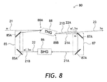
図2および6をさらに参照しながら次に図8を参照すると、第3高調波発生器80は、図2の第3高調波発生器20の変形形態であり、図6のカスケード高調波発生器60の一例として見ることができる。図8の第3高調波発生器80は、第2高調波結晶86を低次高調波発生器66として含み、第3高調波結晶88を高次高調波発生器68として含むことができる。図8の第3高調波発生器80の別個の一特徴は、第3高調波結晶88が、基本光ビーム21の入力に対して、好ましくはブリュースター角だけ傾斜した入力光学面88Aおよび出力光学面88Bを含むことができることである。別の特徴は、第1のビーム・コンバイナ85が上側および下側の転換ミラー85Aを含むことができ、第1のビーム・スプリッタ87が上側および下側の転換ミラー87Aを含むことができることである。上側および下側の転換ミラー85A、87Aは、ダイクロイック・ミラーである必要はなく、すなわち通常のミラーでよく、その場合、ビームの組合せおよび分割の機能が空間多重化によって提供され、すなわち、1つのビームがミラーによって反射されるのに対して、第2のビームは空間的にミラーを迂回する。あるいは、ビームの組合せおよび分割の機能を偏光多重化によって提供することができ、その場合、ビームが相異なる偏光であり、ミラーがある偏光を透過し、他の偏光を反射する。
Referring now to FIG. 8 with further reference to FIGS. 2 and 6, the third
好ましくは、第1の基本光ビーム21および第2高調波光ビーム22が非垂直(鋭角)入射角で第3高調波結晶88の入力光学面88Aに入射するように第3高調波結晶88が配向される。さらに、第1の基本光ビーム21と第2高調波光ビーム22は、互いに対して非ゼロ角(鋭角)を形成することができる。第1の基本光ビーム21は図8の平面内で偏光させることができる。第2高調波結晶26内のSHGはタイプIでよく、図8に対して垂直に偏光された2倍の周波数2ωで第2高調波光ビーム22を発生する。第3高調波結晶88内のTHGはタイプIIでよく、図8の平面内で偏光された第1の基本光ビーム21と、平面に垂直に偏光された第2高調波光ビーム22とを組み合わせ、図8の平面内で偏光された3倍の周波数3ωで第3高調波光ビーム23を発生する。
Preferably, the third harmonic crystal 88 is oriented so that the first
マイクロメートル波長範囲、および約1kWよりも高いピーク入力パワーでは、第2高調波結晶86(図8)は、好ましくは約150℃で非臨界位相整合されたホウ酸リチウム・バリウム(LBO)でよく、第3高調波結晶88(図8)は、図8に垂直に偏光された臨界およびコリニアまたは非コリニア位相整合されたLBOでよい。第3高調波結晶88はブリュースター入射角および退出角を有するので、スペクトル分散、すなわち第3高調波結晶88の屈折率の波長依存性は、第3高調波結晶88の入力面88Aおよび出力面88Bで光ビームの角度を分離することができる。
For the micrometer wavelength range and peak input power higher than about 1 kW, the second harmonic crystal 86 (FIG. 8) may be lithium barium borate (LBO), preferably non-critically phase matched at about 150 ° C. The third harmonic crystal 88 (FIG. 8) may be a critical and collinear or non-collinear phase matched LBO polarized perpendicular to FIG. Since the third harmonic crystal 88 has a Brewster incident angle and a withdrawal angle, the spectral dispersion, that is, the wavelength dependence of the refractive index of the third harmonic crystal 88 is the
この構成の一利点は、第3高調波光ビーム23から残留出力ビーム21Bおよび22Aを分離し、偏光を回転するのに波長板またはダイクロイック・ミラーが不要であることである。実際に、第1のビーム・コンバイナ85の上側転換ミラー85Aは、第2高調波光ビーム22および残留光ビーム21Bを第3高調波結晶88に結合することができる。第1のビーム・スプリッタ87Aの上側転換ミラー87Aは、残留基本光ビーム21Aを分割することができる。第1の基本光ビーム21と第2高調波光ビーム22が第3高調波結晶88の入力面88Aに対する異なる入射角を有するとき、第1の基本光ビーム21および第2高調波光ビーム22は、第3高調波結晶88内でほぼコリニアでよい。1mm範囲のタイプII LBO THG長の例では、ビーム21および22の角度分離は1°〜3°程度であり、ミラー・エッジまたはビーム・ブロックを使用する直接的なビーム分離には十分である。残留基本光ビーム21Aと第3高調波光ビーム23がどちらも低損失ブリュースター透過のためにp偏光されるとき、第3高調波結晶88の出力面88B上に反射防止(AR)被覆が必要ではないことがあるので、ブリュースター表面の使用は有益である。これにより、垂直入射面に対する面88A、88Bの表面積の増大と共に、面88A、88Bの耐UV損傷性が著しく改善される。好ましくは、入力面88Aは、s偏光された第2高調波ビーム22およびp偏光された第1の基本光ビーム21のためにAR被覆することができる。この構成の別の利点は、基本周波数ωの残留ビーム21Bを直ちにダンプする必要がないことである。基本周波数ωの残留ビーム21Bは、第2高調波ビーム22とコリニアとなり、したがって第3高調波結晶88内の第1の基本光ビーム21とコリニアとはならず、したがってTHGプロセスと干渉する可能性は低く、残留第2高調波ビーム22Aと共にコリニアに退出し、そこで第3高調波光ビーム23から両方を分離することができ、図示されていない1つの共通光ビーム・ダンプ内に放出することができるからである。図2と同様に、レンズまたは他の光学系を追加して、結晶で適切なビーム・サイズおよび空間プロファイルを生成することができる。
One advantage of this configuration is that no waveplate or dichroic mirror is required to separate the
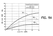
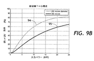
図1および2をさらに参照しながら図9Aおよび9Bを参照すると、図2(図9B)の第3高調波発生器20の計算光変換効率が、図1(図9A)の従来型光周波数3倍器10のものと比較される。図9Aおよび9Bではどちらも、光変換効率が、kW単位の入力光パワーの関数として、25kW入力光パワー・レベルまでプロットされる。
9A and 9B with further reference to FIGS. 1 and 2, the calculated light conversion efficiency of the third
図1をさらに参照しながら特に図9Aを参照すると、70マイクロメートル第2高調波ビーム14直径(91)、200マイクロメートル第2高調波ビーム14直径(92)、および350マイクロメートル第2高調波ビーム14直径(93)について光変換効率がプロットされる。入力波長は1064nmであり、パルス持続時間は通常、数十ナノ秒である。SHG12とTHG13の結晶はどちらもLBOである。第2高調波結晶12は15mmの長さであり、基本ビーム11の140マイクロメートル直径スポットにおいて約150℃でタイプI非臨界位相整合される。第3高調波結晶13は20mmの長さであり、位相整合はタイプII臨界、非コリニア位相整合である。最高の変換効率91は、70マイクロメートルの第2高調波ビーム14のスポット直径に対応し、これは、20kW入力パワーで最良の変換を実現することができる。中間変換効率92および下端変換効率93は、それぞれ200マイクロメートルおよび350マイクロメートルの第2高調波ビーム14のスポット直径に対応する。これらのスポット直径の結果、効率92および93が得られ、これらは、より大きなスポット・サイズ、したがって改善されるビーム品質および結晶12および13の寿命とトレードオフされる。従来技術の周波数3倍器10に対する25kW入力パワー・レベルで、70マイクロメートル入力スポット・サイズの結果、63%の変換効率91が得られ、200マイクロメートル・スポット・サイズの結果、37%の変換効率92が得られ、350マイクロメートル・スポット・サイズの結果、20%よりほんの少し下の変換効率93が得られる。
With particular reference to FIG. 9A with further reference to FIG. 1, a 70 micrometer second
次に、図2をさらに参照しながら特に図9Bを参照すると、最高の光変換効率94は、図2の光高調波発生器20内の第2高調波ビーム22の200マイクロメートル・ビーム直径に対応する。2番目に高い変換効率95は、図2の光高調波発生器20内の第2高調波ビーム22の350マイクロメートル・ビーム直径に対応する。
Next, with particular reference to FIG. 9B, with further reference to FIG. 2, the highest
図9Aと9Bとの比較により、図1の従来技術の光周波数3倍器10と比べて、図2の光高調波発生器20のずっと高い変換効率が明らかとなる。例えば、図2の第3高調波発生器20に対する25kW入力パワー・レベルで、200マイクロメートル・スポット・サイズの結果、81%の変換効率が得られ、350マイクロメートル・スポット・サイズの結果、65%の変換効率が得られる。したがって、本開示の第3高調波発生器20は、70マイクロメートル第2高調波ビーム14直径での従来型周波数3倍器10よりも、200マイクロメートル第2高調波ビーム22直径で高い変換効率を実現することができる。
A comparison of FIGS. 9A and 9B reveals a much higher conversion efficiency of the optical
図2および6をさらに参照しながら図10を参照すると、主光ビーム61(図6)からのカスケード光高調波発生の方法100(図10)は、低次高調波光ビーム62を発生する低次光高調波発生器66と、高調波光ビーム63を発生する高次光高調波発生器68とを用意するステップ101を含むことができる。次のステップ102では、主光ビーム61を、高次高調波発生器68を通じて、次いで、低次高調波発生器66を通じて伝播することによって低次高調波光ビーム62を発生するように低次高調波発生器66を通じて、順々に伝播することができ、したがって、低次高調波光ビーム62が低次高調波発生器66内の主光ビーム61と重複する。次のステップ103では、低次高調波発生器66によって発生された低次高調波光ビーム62が高次高調波発生器68を通じて伝播し、したがって、高次高調波光ビーム63を発生するように、低次高調波光ビーム62が高次高調波発生器68内の主光ビーム61と重複する。さらに、任意選択のステップ104では、低次高調波発生器66から出る残留主光ビーム62A、および/または他の残留ビームを低次高調波光ビームから分離することができ、光ダンプ29A、29B内にダンプすることができる。
Referring to FIG. 10 with further reference to FIGS. 2 and 6, the method 100 (FIG. 10) of cascading optical harmonic generation from the main light beam 61 (FIG. 6) provides a low-order harmonic
図8の光高調波発生器80と同様に、高次高調波発生器68に入射する低次高調波光ビーム62は、高次高調波発生器68内のコリニア伝播のために、高次高調波発生器68に入射する主光ビーム61と鋭角を形成することができる。さらに、主光ビームを、低次高調波発生器66および高次高調波発生器68を備える光ループ69内の光ラウンド・トリップ時間のほぼ整数倍のパルス間隔でパルシングすることができる。
Similar to the optical
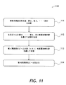
図10の方法100は、高次カスケード高次高調波発生、例えば第4高調波(図4)、第5高調波の発生について一般化することができる。図11を参照すると、主光ビームからのカスケード光高調波発生の方法110は、m=2、...、M、Mが整数≧3として、少なくとも1つの第m高調波発生器を含む複数の高調波発生器を用意するステップ111を含む。次のステップ112では、第M高調波発生器から開始して、第2高調波発生器で終了する、mの降順で複数の高調波発生器を通じて主光ビームを伝播することができる。例示として、再び図5Aをしばらくの間参照すると、第4高調波光ビーム41が、第4高調波結晶46、第3高調波結晶28、および第2高調波結晶26を通じて伝播する。
The
次のステップ113では、n=2、...、M−1として、第(n+1)高調波発生器を通じて、その中で主光ビームと重複するように、各第n高調波光ビームを伝播することができる。例えば、再び図5Bおよび5Cを参照すると、第2高調波光ビーム22が第3高調波結晶28(図5B)を通じて伝播し、第3高調波光ビーム23が第4高調波結晶46(図5C)を通じて伝播する。最後に、ステップ114では、第M高調波光ビームが出力される。例として、再び図5Dを参照すると、第4高調波結晶46から第4高調波ビーム24を出力することができる。一実施形態では、主光ビームの光路が閉光ループを形成しないように、すなわち開ループになるように主光ビームが伝播する。
In the
本開示は、本明細書で説明した特定の実施形態によって範囲が限定されるべきではない。実際に、本明細書で説明したものに加えて、他の様々な実施形態および修正形態が、上記の説明および添付の図面から当業者には明らかとなるであろう。したがって、そのような他の実施形態および修正形態は、本開示の範囲内に包含されるものとする。さらに、本明細書では特定の目的のための特定の環境内の特定の実装の文脈で本開示を説明したが、その有用性はそれに限定されないこと、および任意の数の目的のための任意の数の環境で本開示を有益に実装できることを当業者は理解するであろう。したがって、以下に記載の特許請求の範囲は、本明細書で説明される本開示の最大限の幅および精神に鑑みて解釈されるべきである。 The present disclosure should not be limited in scope by the specific embodiments described herein. Indeed, various other embodiments and modifications in addition to those described herein will become apparent to those skilled in the art from the foregoing description and accompanying drawings. Accordingly, such other embodiments and modifications are intended to be included within the scope of the present disclosure. Further, although this disclosure has described this disclosure in the context of a particular implementation within a particular environment for a particular purpose, its usefulness is not limited thereto, and any number of purposes for any number of purposes. Those skilled in the art will appreciate that the present disclosure may be beneficially implemented in a number of environments. Accordingly, the claims set forth below should be construed in view of the full breadth and spirit of the present disclosure as described herein.
10 カスケード高調波3倍器
11 基本光ビーム
12 第2高調波結晶
13 第3高調波結晶
14 第2高調波ビーム
15 ダイクロイック・ミラー
19 第3高調波ビーム
20 第3高調波発生器
21 第1基本光ビーム
21A 残留基本光ビーム
21B 残留ビーム
22 第2高調波光ビーム
22A 残留第2高調波ビーム
23 第3高調波光ビーム
24 第4高調波光ビーム
25 第1のビーム・コンバイナ
25A ダイクロイック・ミラー
26 第2高調波結晶
27 第1のビーム・スプリッタ
27A 上側ダイクロイック・ミラー
27B 下側ダイクロイック・ミラー
28 第3高調波結晶
29A 光ビーム・ダンプ
29B 光ビーム・ダンプ
40 第4高調波発生器
41 第2の基本光ビーム
45 第2のビーム・コンバイナ
45A ダイクロイック・ミラー
45B 転換ミラー
46 第4高調波結晶
47 第2高調波スプリッタ
49 上部光ビーム・ダンプ
60 カスケード高調波発生器
61 主光ビーム
61A 残留主光ビーム
61B 残留ビーム
62 低次高調波光ビーム
63 高調波光ビーム
65 高調波コンバイナ
66 低次高調波発生器
67 高調波分離器
68 高次高調波発生器
69 光ループ
70 カスケード高調波発生器
71 パルス光源
80 第3高調波発生器
85 第1のビーム・コンバイナ
85A 転換ミラー
86 第2高調波結晶
87 第1のビーム・スプリッタ
87A 転換ミラー
88 第3高調波結晶
88A 入力光学面
88B 出力光学面
DESCRIPTION OF
Claims (24)
前記第1の基本光ビームおよび前記第2高調波光ビームから第3高調波光ビームを発生する、前記第1のビーム・コンバイナに結合された第3高調波結晶であって、前記第3高調波光ビームの発生時に、残留基本光ビームが前記第3高調波結晶から出る第3高調波結晶と、
前記残留基本光ビームと前記第3高調波光ビームとを分離する、前記第3高調波結晶に結合された第1のビーム・スプリッタと、
前記残留基本光ビームから前記第2高調波光ビームを発生し、前記第2高調波光ビームを前記第1のビーム・コンバイナに結合する、前記第1のビーム・スプリッタに結合された第2高調波結晶と
を備える第3高調波発生器。 A first beam combiner that combines a first fundamental light beam with a second harmonic light beam;
A third harmonic crystal coupled to the first beam combiner for generating a third harmonic light beam from the first fundamental light beam and the second harmonic light beam, the third harmonic light beam; A third harmonic crystal in which a residual fundamental light beam emerges from the third harmonic crystal when
A first beam splitter coupled to the third harmonic crystal for separating the residual fundamental light beam and the third harmonic light beam;
A second harmonic crystal coupled to the first beam splitter that generates the second harmonic light beam from the residual fundamental light beam and couples the second harmonic light beam to the first beam combiner. A third harmonic generator comprising:
第2の基本光ビームを、前記第3高調波結晶によって発生された前記第3高調波光ビームと組み合わせる第2のビーム・コンバイナと、
前記第2の基本光ビームおよび前記第3高調波光ビームから第4高調波光ビームを発生する、前記第2のビーム・コンバイナに結合された第4高調波結晶であって、前記第4高調波光ビームの発生時に、前記第1の基本光ビームが第4高調波結晶から出る第4高調波結晶と、
前記第1の基本光ビームと前記第4高調波光ビームとを分離し、前記第1の基本光ビームを前記第3高調波発生器の前記第1のビーム・コンバイナに結合する、前記第4高調波結晶に結合された第2のビーム・スプリッタと
を備える第4高調波発生器。 A third harmonic generator according to claim 1;
A second beam combiner that combines a second fundamental light beam with the third harmonic light beam generated by the third harmonic crystal;
A fourth harmonic crystal coupled to the second beam combiner for generating a fourth harmonic light beam from the second fundamental light beam and the third harmonic light beam, wherein the fourth harmonic light beam; A fourth harmonic crystal in which the first fundamental light beam emerges from the fourth harmonic crystal when
Separating the first fundamental light beam and the fourth harmonic light beam and coupling the first fundamental light beam to the first beam combiner of the third harmonic generator; A fourth harmonic generator comprising a second beam splitter coupled to the wave crystal.
高次高調波光ビームを発生すると共に、残留低次高調波光ビームを透過する、前記主光ビームの経路内に配設された高次高調波発生器と、
低次高調波光ビームを発生すると共に、残留主光ビームを透過する、前記高次高調波発生器の下流側の前記主光ビームの前記経路内に配設された低次高調波発生器と、
前記高次高調波発生器を通じて伝播する前記主光ビームから前記高次高調波光ビームを分割する、前記高次高調波発生器と前記低次高調波発生器との間の前記主光ビームの前記経路内に配設された高調波分離器と、
前記低次高調波発生器によって発生された前記低次高調波光ビームを、前記高次高調波光ビームを発生する前記高次高調波発生器に結合する、前記低次高調波発生器の下流側の前記残留主光ビームの前記経路内に配設された高調波コンバイナと
を備えるカスケード高調波発生器。 A cascade harmonic generator that generates cascade optical harmonics from a main light beam,
A high-order harmonic generator disposed in the path of the main light beam that generates a high-order harmonic light beam and transmits the residual low-order harmonic light beam;
A low-order harmonic generator disposed in the path of the main light beam downstream of the high-order harmonic generator that generates a low-order harmonic light beam and transmits a residual main light beam;
The main light beam between the high-order harmonic generator and the low-order harmonic generator that splits the high-order harmonic light beam from the main light beam propagating through the high-order harmonic generator. A harmonic separator disposed in the path;
Coupling the low-order harmonic light beam generated by the low-order harmonic generator to the high-order harmonic generator that generates the high-order harmonic light beam, downstream of the low-order harmonic generator A cascade harmonic generator comprising a harmonic combiner disposed in the path of the residual main light beam.
低次高調波光ビームを発生するために、高次高調波発生器を通じて、次いで低次高調波発生器を通じて、主光ビームを順々に伝播するステップと、
高次高調波光ビームを発生するために、前記低次高調波光ビームが前記高次高調波発生器内で前記主光ビームと重複するように、前記高次高調波発生器を通じて、前記低次高調波発生器によって発生された前記低次高調波光ビームを伝播するステップと
を含む方法。 A method of generating cascade optical harmonics from a main light beam,
Sequentially propagating the main light beam through a high order harmonic generator and then through a low order harmonic generator to generate a low order harmonic light beam;
In order to generate a high order harmonic light beam, the low order harmonic light beam is passed through the high order harmonic generator so that the low order harmonic light beam overlaps the main light beam in the high order harmonic light generator. Propagating the low-order harmonic light beam generated by a wave generator.
m=2、...、M、M≧3として、第m高調波発生器のそれぞれ1つを備える複数の高調波発生器を用意するステップと、
前記第M高調波発生器から開始して、前記第2高調波発生器で終了する、mの降順で前記複数の高調波発生器を通じて前記主光ビームを伝播するステップと、
n=2、...、M−1として、第(n+1)高調波発生器を通じて、その中で前記主光ビームと重複するように、各第n高調波光ビームを伝播するステップと、
前記第M高調波光ビームを出力するステップと
を含む方法。 A method of generating cascade optical harmonics from a main light beam,
m = 2,. . . , M, M ≧ 3, providing a plurality of harmonic generators each having one of the mth harmonic generators;
Propagating the main light beam through the plurality of harmonic generators in descending order of m, starting with the Mth harmonic generator and ending with the second harmonic generator;
n = 2,. . . , M-1, through each nth harmonic light beam through the (n + 1) th harmonic generator so as to overlap the main light beam therein,
Outputting the Mth harmonic light beam.
Applications Claiming Priority (2)
| Application Number | Priority Date | Filing Date | Title |
|---|---|---|---|
| US201462002006P | 2014-05-22 | 2014-05-22 | |
| US62/002,006 | 2014-05-22 |
Publications (3)
| Publication Number | Publication Date |
|---|---|
| JP2015222425A true JP2015222425A (en) | 2015-12-10 |
| JP2015222425A5 JP2015222425A5 (en) | 2018-06-21 |
| JP6478804B2 JP6478804B2 (en) | 2019-03-06 |
Family
ID=53275992
Family Applications (1)
| Application Number | Title | Priority Date | Filing Date |
|---|---|---|---|
| JP2015103687A Active JP6478804B2 (en) | 2014-05-22 | 2015-05-21 | Cascaded optical harmonic generation |
Country Status (3)
| Country | Link |
|---|---|
| US (1) | US9377667B2 (en) |
| EP (1) | EP2947509B1 (en) |
| JP (1) | JP6478804B2 (en) |
Cited By (1)
| Publication number | Priority date | Publication date | Assignee | Title |
|---|---|---|---|---|
| JP2019518984A (en) * | 2016-07-13 | 2019-07-04 | シャープ株式会社 | Compact and effective beam absorber for frequency conversion lasers |
Families Citing this family (9)
| Publication number | Priority date | Publication date | Assignee | Title |
|---|---|---|---|---|
| US9568803B2 (en) | 2014-05-22 | 2017-02-14 | Lumentum Operations Llc | Cascaded optical harmonic generation |
| US10228607B2 (en) | 2014-05-22 | 2019-03-12 | Lumentum Operations Llc | Second harmonic generation |
| JP6286089B2 (en) * | 2016-06-08 | 2018-02-28 | ルーメンタム オペレーションズ エルエルシーLumentum Operations LLC | Cascade optical harmonic generation |
| CN109560450A (en) * | 2017-09-26 | 2019-04-02 | 朗美通经营有限责任公司 | Second_harmonic generation |
| US10983260B2 (en) | 2018-10-26 | 2021-04-20 | Coherent, Inc. | Third-harmonic generating apparatus for laser-radiation having polarization loop |
| US11404841B2 (en) * | 2019-08-20 | 2022-08-02 | Coherent, Inc. | Optical parametric chirped-pulse amplifier |
| US20240385495A1 (en) * | 2021-04-26 | 2024-11-21 | Massachusetts Institute Of Technology | Methods And Apparatus To Generate Terahertz Waves Through Cascaded Nonlinear Processes |
| US12463397B2 (en) | 2022-04-08 | 2025-11-04 | Microsoft Technology Licensing, Llc | Generating multiple beams of a harmonic frequency |
| US20240255829A1 (en) * | 2023-01-31 | 2024-08-01 | Cornell University | Third-harmonic frequency generator and generation method |
Citations (6)
| Publication number | Priority date | Publication date | Assignee | Title |
|---|---|---|---|---|
| JP2002542632A (en) * | 1999-04-15 | 2002-12-10 | コヒーレント・インク | Dual active resonator type CW deep ultraviolet laser system |
| JP2003121895A (en) * | 2001-10-10 | 2003-04-23 | Sumitomo Heavy Ind Ltd | Harmonic generator, laser annealing apparatus, and harmonic generation method |
| JP2009128435A (en) * | 2007-11-20 | 2009-06-11 | Mitsubishi Electric Corp | Wavelength conversion device and wavelength conversion laser device |
| WO2009093289A1 (en) * | 2008-01-25 | 2009-07-30 | Shimadzu Corporation | Semiconductor laser excited solid-state laser device |
| JP2009198606A (en) * | 2008-02-19 | 2009-09-03 | Panasonic Corp | Wavelength converting apparatus |
| US20130294465A1 (en) * | 2012-05-07 | 2013-11-07 | Continuum | HIGHLY EFFICIENT 3rd HARMONIC GENERATION IN Nd: YAG LASER |
Family Cites Families (10)
| Publication number | Priority date | Publication date | Assignee | Title |
|---|---|---|---|---|
| JPH03145777A (en) * | 1989-10-31 | 1991-06-20 | Hoya Corp | Harmonic generating laser device |
| US5452312A (en) * | 1993-10-18 | 1995-09-19 | Matsushita Electric Industrial Co., Ltd. | Short-wavelength laser light source and optical information processing aparatus |
| GB9614037D0 (en) * | 1996-07-04 | 1996-09-04 | Secr Defence | An harmonic generator |
| US5850407A (en) | 1997-11-25 | 1998-12-15 | Lightwave Electronics Corporation | Third-harmonic generator with uncoated brewster-cut dispersive output facet |
| JP3413481B2 (en) * | 1999-03-30 | 2003-06-03 | 住友重機械工業株式会社 | Laser drilling method and processing apparatus |
| CN100582909C (en) * | 2005-02-25 | 2010-01-20 | 松下电器产业株式会社 | Wavelength conversion optical device, laser light source, and image display optical device |
| US20090161703A1 (en) * | 2007-12-20 | 2009-06-25 | Wolf Seelert | SUM-FREQUENCY-MIXING Pr:YLF LASER APPARATUS WITH DEEP-UV OUTPUT |
| US7903701B2 (en) * | 2009-03-27 | 2011-03-08 | Electro Scientific Industries, Inc. | Intracavity harmonic generation using a recycled intermediate harmonic |
| US20130077086A1 (en) * | 2011-09-23 | 2013-03-28 | Kla-Tencor Corporation | Solid-State Laser And Inspection System Using 193nm Laser |
| US9509112B2 (en) * | 2013-06-11 | 2016-11-29 | Kla-Tencor Corporation | CW DUV laser with improved stability |
-
2015
- 2015-05-21 JP JP2015103687A patent/JP6478804B2/en active Active
- 2015-05-21 EP EP15168631.8A patent/EP2947509B1/en active Active
- 2015-05-22 US US14/719,617 patent/US9377667B2/en active Active
Patent Citations (6)
| Publication number | Priority date | Publication date | Assignee | Title |
|---|---|---|---|---|
| JP2002542632A (en) * | 1999-04-15 | 2002-12-10 | コヒーレント・インク | Dual active resonator type CW deep ultraviolet laser system |
| JP2003121895A (en) * | 2001-10-10 | 2003-04-23 | Sumitomo Heavy Ind Ltd | Harmonic generator, laser annealing apparatus, and harmonic generation method |
| JP2009128435A (en) * | 2007-11-20 | 2009-06-11 | Mitsubishi Electric Corp | Wavelength conversion device and wavelength conversion laser device |
| WO2009093289A1 (en) * | 2008-01-25 | 2009-07-30 | Shimadzu Corporation | Semiconductor laser excited solid-state laser device |
| JP2009198606A (en) * | 2008-02-19 | 2009-09-03 | Panasonic Corp | Wavelength converting apparatus |
| US20130294465A1 (en) * | 2012-05-07 | 2013-11-07 | Continuum | HIGHLY EFFICIENT 3rd HARMONIC GENERATION IN Nd: YAG LASER |
Cited By (1)
| Publication number | Priority date | Publication date | Assignee | Title |
|---|---|---|---|---|
| JP2019518984A (en) * | 2016-07-13 | 2019-07-04 | シャープ株式会社 | Compact and effective beam absorber for frequency conversion lasers |
Also Published As
| Publication number | Publication date |
|---|---|
| US9377667B2 (en) | 2016-06-28 |
| US20150338719A1 (en) | 2015-11-26 |
| EP2947509B1 (en) | 2022-04-13 |
| EP2947509A1 (en) | 2015-11-25 |
| JP6478804B2 (en) | 2019-03-06 |
Similar Documents
| Publication | Publication Date | Title |
|---|---|---|
| JP6478804B2 (en) | Cascaded optical harmonic generation | |
| Cerullo et al. | Ultrafast optical parametric amplifiers | |
| JP4820904B2 (en) | Spectral doubling-mediated chirped pulse amplifier using third-order dispersion chirping | |
| US5936983A (en) | Third harmonic generation apparatus | |
| EP2376980B1 (en) | Frequency-tripled fiber mopa | |
| CN110286542B (en) | Device for generating laser radiation triple rate | |
| US9280031B2 (en) | Methods and apparatus for idler extraction in high power optical parametric amplifiers | |
| US20030043452A1 (en) | Device for the frequency conversion of a fundamental laser frequency to other frequencies | |
| US8373924B2 (en) | Frequency-tripled fiber MOPA | |
| CN111064071A (en) | High-power triple-frequency ultraviolet femtosecond laser | |
| CN111106521A (en) | Sum frequency device and laser | |
| US10228607B2 (en) | Second harmonic generation | |
| CN113366712A (en) | Multi-stage parametric module and picosecond pulse laser source comprising same | |
| EP3798723B1 (en) | Multistage parametric light amplification method and multistage amplifier | |
| WO2022104597A1 (en) | Polarization-insensitive optical parametric amplifier for radially polarized light and amplification method | |
| US10642127B1 (en) | Single Crystal optical parametric amplifier | |
| US9568803B2 (en) | Cascaded optical harmonic generation | |
| CN105790045B (en) | Big energy period magnitude superelevation signal-to-noise ratio femtosecond seed pulse generation device | |
| US10852621B1 (en) | System and method for generating multiple simultaneous, co-propagating wavelengths via nonlinear wavelength conversion | |
| JP6286089B2 (en) | Cascade optical harmonic generation | |
| CN109560450A (en) | Second_harmonic generation | |
| CN120601240A (en) | Device and method for generating GHz repetition frequency high-power femtosecond green light and ultraviolet laser | |
| Roissé et al. | Walk-off and phase-compensated resonantly enhanced frequency-doubling of picosecond pulses using type II nonlinear crystal | |
| CN111129935A (en) | Sum frequency method | |
| US20120176666A1 (en) | Laser apparatus and method to generate uv laser light |
Legal Events
| Date | Code | Title | Description |
|---|---|---|---|
| RD02 | Notification of acceptance of power of attorney |
Free format text: JAPANESE INTERMEDIATE CODE: A7422 Effective date: 20160524 |
|
| RD04 | Notification of resignation of power of attorney |
Free format text: JAPANESE INTERMEDIATE CODE: A7424 Effective date: 20160603 |
|
| A711 | Notification of change in applicant |
Free format text: JAPANESE INTERMEDIATE CODE: A711 Effective date: 20160708 |
|
| A521 | Request for written amendment filed |
Free format text: JAPANESE INTERMEDIATE CODE: A523 Effective date: 20180508 |
|
| A621 | Written request for application examination |
Free format text: JAPANESE INTERMEDIATE CODE: A621 Effective date: 20180508 |
|
| A871 | Explanation of circumstances concerning accelerated examination |
Free format text: JAPANESE INTERMEDIATE CODE: A871 Effective date: 20180508 |
|
| A977 | Report on retrieval |
Free format text: JAPANESE INTERMEDIATE CODE: A971007 Effective date: 20180817 |
|
| A975 | Report on accelerated examination |
Free format text: JAPANESE INTERMEDIATE CODE: A971005 Effective date: 20180820 |
|
| A131 | Notification of reasons for refusal |
Free format text: JAPANESE INTERMEDIATE CODE: A131 Effective date: 20180828 |
|
| A521 | Request for written amendment filed |
Free format text: JAPANESE INTERMEDIATE CODE: A523 Effective date: 20181126 |
|
| TRDD | Decision of grant or rejection written | ||
| A01 | Written decision to grant a patent or to grant a registration (utility model) |
Free format text: JAPANESE INTERMEDIATE CODE: A01 Effective date: 20190115 |
|
| A61 | First payment of annual fees (during grant procedure) |
Free format text: JAPANESE INTERMEDIATE CODE: A61 Effective date: 20190205 |
|
| R150 | Certificate of patent or registration of utility model |
Ref document number: 6478804 Country of ref document: JP Free format text: JAPANESE INTERMEDIATE CODE: R150 |
|
| R250 | Receipt of annual fees |
Free format text: JAPANESE INTERMEDIATE CODE: R250 |
|
| R250 | Receipt of annual fees |
Free format text: JAPANESE INTERMEDIATE CODE: R250 |
|
| R250 | Receipt of annual fees |
Free format text: JAPANESE INTERMEDIATE CODE: R250 |
|
| R250 | Receipt of annual fees |
Free format text: JAPANESE INTERMEDIATE CODE: R250 |
|
| R250 | Receipt of annual fees |
Free format text: JAPANESE INTERMEDIATE CODE: R250 |