JP2015225747A - Perfect square conductor wire for coil, perfect square insulation electric wire using it, and coil using the perfect square insulation electric wire - Google Patents
Perfect square conductor wire for coil, perfect square insulation electric wire using it, and coil using the perfect square insulation electric wire Download PDFInfo
- Publication number
- JP2015225747A JP2015225747A JP2014108913A JP2014108913A JP2015225747A JP 2015225747 A JP2015225747 A JP 2015225747A JP 2014108913 A JP2014108913 A JP 2014108913A JP 2014108913 A JP2014108913 A JP 2014108913A JP 2015225747 A JP2015225747 A JP 2015225747A
- Authority
- JP
- Japan
- Prior art keywords
- coil
- wire
- square
- conductor wire
- electric wire
- Prior art date
- Legal status (The legal status is an assumption and is not a legal conclusion. Google has not performed a legal analysis and makes no representation as to the accuracy of the status listed.)
- Granted
Links
Images
Landscapes
- Conductive Materials (AREA)
- Non-Insulated Conductors (AREA)
- Insulated Conductors (AREA)
Abstract
Description
本発明は、コイル用真四角導体線及び真四角絶縁電線、並びにそれを用いたコイルに関する。 The present invention relates to a true square conductor wire for a coil, a true square insulated wire, and a coil using the same.
携帯電話等のモバイル機器のインダクタ部品では、電池の長寿命化を図るため、コイルの小型化及び高占積率化が求められている。そして、かかる要求に応えるコイルとして、横断面形状が正方形である真四角絶縁電線(以下、「電線」ともいう)を巻回した構成のものが挙げられる。 Inductor parts of mobile devices such as mobile phones are required to have a smaller coil and a higher space factor in order to extend the battery life. And as a coil which respond | corresponds to this request | requirement, the thing of the structure which wound the square-shaped insulated wire (henceforth "electric wire") whose cross-sectional shape is a square is mentioned.
例えば、特許文献1には、冷間加工により平角状に形成した銅線の外周に電着塗装で絶縁層を設けたコイル用平角電線が開示されている。特許文献2には、外周形状を例えば正六角形等の隣接する絶縁電線と密接する形状に形成したコイル用平角電線が開示されている。 For example, Patent Document 1 discloses a rectangular electric wire for a coil in which an insulating layer is provided by electrodeposition coating on the outer periphery of a copper wire formed into a rectangular shape by cold working. Patent Document 2 discloses a rectangular electric wire for a coil in which the outer peripheral shape is formed into a shape in close contact with an adjacent insulated wire such as a regular hexagon.
コイルの小型化を図るために電線の曲げ径を小さくすると、電線の弾性反発力が大きくなるため、電線間を熱可塑性樹脂の融着層が介在してコイル形状を保持していても、例えばコイルをリフローや磁性粉を用いた高温焼結のために高温下熱処理した場合、融着層が融解して電線の弾性反発力によりコイル形状が解けてしまうという問題がある。 If the bend diameter of the wire is reduced in order to reduce the size of the coil, the elastic repulsion force of the wire will increase, so even if the coil shape is maintained with a fusion layer of thermoplastic resin between the wires, for example, When the coil is heat-treated at a high temperature for reflow or high-temperature sintering using magnetic powder, there is a problem that the fused layer is melted and the coil shape is unwound by the elastic repulsion of the electric wire.
本発明の課題は、コイル形状の保持性能を高めることである。 The subject of this invention is improving the holding | maintenance performance of a coil shape.
本発明は、横断面の形状が正方形のコイル用真四角導体線であって、前記真四角導体線は、純度が99.99wt%以上のCuと不可避不純物からなり、且つ0.2%耐力が100MPa以下である。 The present invention is a square conductor wire for a coil having a square cross-sectional shape, and the conductor wire is made of Cu having a purity of 99.99 wt% or more and inevitable impurities, and has a 0.2% proof stress. 100 MPa or less.
本発明によれば、真四角導体線は、純度が99.99wt%以上のCuと不可避不純物からなり、且つ0.2%耐力が100MPa以下であることから、柔らかく、従って、曲げ径が小さいコイルであっても、高いコイル形状の保持性能を得ることができる。 According to the present invention, a square conductor wire is composed of Cu having a purity of 99.99 wt% or more and inevitable impurities, and has a 0.2% proof stress of 100 MPa or less, so that it is soft and therefore has a small bending diameter. Even so, a high coil-shaped holding performance can be obtained.
以下、実施形態について図面に基づいて詳細に説明する。 Hereinafter, embodiments will be described in detail based on the drawings.
(コイル用真四角導体線)
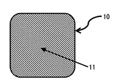
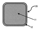
図1は、実施形態に係るコイル用真四角導体線10の横断面図を示す。図2はコイル用真四角導体線の外周に絶縁層を形成した真四角絶縁電線20の横断面図を示す。本実施形態に係る真四角絶縁電線20は、携帯電話等のモバイル機器のインダクタ部品としてのコイルを製造するためのものである。
(Square conductor wire for coil)
FIG. 1 shows a cross-sectional view of a
本実施形態に係るコイル用真四角導体線10は、横断面が正方形の導体線で形成される。本発明がいう「正方形」とは、図1に示すような角部が円弧状に形成されたものも含まれる。コイル用真四角導体線の1辺は、0.01mm〜5mmで、特に小型のコイルを製造するためのものでは、1辺が、0.05mm〜0.8mmである。
The
コイル用真四角導体線10は、純度が99.99wt%以上のCuと不可避不純物で形成されている。不可避不純物とは、例えば、ヒ素(As)、アンチモン(Sb)、ビスマス(Bi)、鉛(Pb),硫黄(S)、鉄(Fe)等が挙げられる。これら不可避不純物の合計が、0.01wt%未満である。
好ましいコイル用真四角導体線は、純度が99.999wt%以上のCuと不可避不純物で形成され、より好ましいコイル用真四角導体線は、純度が99.9999wt%以上のCuと不可避不純物で形成されたものである。
純度が99.99wt%未満のCuと不可避不純物で形成された場合、コイル形状の保持性能が悪くなる。
The
A preferable square conductor wire for a coil is formed of Cu having a purity of 99.999 wt% or more and unavoidable impurities, and a more preferable rectangular conductor wire for a coil is formed of Cu having a purity of 99.9999 wt% or more and an unavoidable impurity. It is a thing.
When the purity is less than 99.99 wt% Cu and inevitable impurities, the coil shape retention performance is deteriorated.
コイル用真四角導体線10の0.2%耐力は100MPa以下であり、コイル形状の保持性能の観点から、好ましくは80MPa以下、より好ましくは60MPa以下であり、また、好ましくは40MPa以上、より好ましくは50MPa以上である。0.2%耐力が100MPaを超えると、コイルを形成した時に反発力が蓄積し、例えばコイルをリフローや磁性粉を用いた高温焼結のために高温下熱処理した場合コイル形状を維持できない。ここで、0.2%耐力は、JIS Z2241 13(耐力)のオフセット法に基づいて測定される。
The 0.2% proof stress of the coiled
また、コイル用真四角導体線(Cu)の結晶粒度は、60μm〜250μmが好ましく、より好ましくは80μm〜180μm、さらに好ましくは100〜160μmである。結晶粒度が60μm未満であるとコイルを形成した時に反発力が蓄積し、例えばコイルをリフローや磁性粉を用いた高温焼結のために高温下熱処理した場合コイル形状を維持できない傾向になる。結晶粒度が250μmを超えるとコイル形状に加工するとき、導体表面に凸凹が生じ易くなり、後述する絶縁層と導体線との密着性が低下する傾向となる。ここで、銅の結晶粒度は、JIS H0501に基づいて測定される。 Further, the crystal grain size of the square conductor wire (Cu) for coil is preferably 60 μm to 250 μm, more preferably 80 μm to 180 μm, and still more preferably 100 to 160 μm. When the crystal grain size is less than 60 μm, repulsive force is accumulated when the coil is formed. For example, when the coil is heat-treated at a high temperature for reflow or high-temperature sintering using magnetic powder, the coil shape tends not to be maintained. When the crystal grain size exceeds 250 μm, unevenness tends to occur on the conductor surface when processing into a coil shape, and the adhesion between an insulating layer and a conductor wire, which will be described later, tends to decrease. Here, the crystal grain size of copper is measured based on JIS H0501.
導体線11の体積固有抵抗は、好ましくは1.73μΩ・cm以下、より好ましくは1.72μΩ・cm以下である。ここで、抵抗率は、JIS C3216−5 3項に基づいて測定される。
The volume resistivity of the
絶縁層12は公知の絶縁材料で構成されている。具体的な絶縁材料としては、エポキシ樹脂、ポリイミド樹脂、ポリアミド樹脂、アクリル樹脂、ポリウレタン樹脂、ポリエステル樹脂、ポリエステルイミド樹脂、ポリビニルホルマール樹脂等が挙げられる。真四角導体線の外周に絶縁層を形成させる方法としては、公知の方法(ディッピング→焼付け、電着→焼付け、噴霧→焼付けなど)を適用すればよいが、導体線の横断面形状が正方形であるので、コーナー部への良好な絶縁層の形成ができる点で、電着による絶縁層の形成が好ましい。絶縁層の厚さは、特に限定されないが、3μm〜200μm、好ましくは、5μm〜100μm、より好ましくは、7〜50μmである。
The insulating
(コイル用真四角導体線、真四角絶縁電線の製造方法)
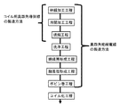
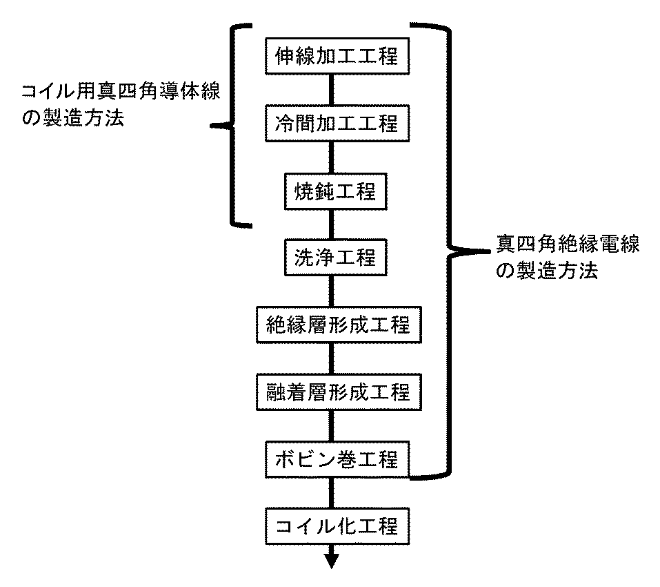
実施形態に係るコイル用真四角導体線10の製造方法は、図3に示す通り、伸線加工工程、冷間加工工程、焼鈍工程を含む。また、真四角絶縁電線の製造方法は、前記伸線加工工程、冷間加工工程、焼鈍工程の後、引続いて洗浄工程、及び絶縁層形成工程を含む。さらに、融着層を形成する場合は、絶縁層形成工程の後、融着層形成工程を経て、ボビンに巻き取られる。
(Manufacturing method of square conductor wire for coil and square insulated wire)
The manufacturing method of the
ここで、これらの工程は、それぞれの工程をバッチ式で行ってもよく、また、全ての工程を連続式で行ってもよく、さらに、例えば伸線加工工程及び冷間加工工程を連続式で行った後、焼鈍工程のみをバッチ式で行い、それ以降の洗浄工程及び絶縁層形成工程を連続式で行う場合のようにバッチ式と連続式とを組み合わせて行ってもよい。 Here, as for these processes, each process may be performed in a batch system, and all processes may be performed in a continuous system. Further, for example, a wire drawing process and a cold processing process are performed in a continuous system. After performing, only an annealing process may be performed by a batch type, and it may carry out combining a batch type and a continuous type like the case where the subsequent washing process and insulating layer formation process are performed by a continuous type.
<伸線加工工程>
伸線加工工程では、母線として純度が99.99wt%以上のCuと不可避不純物からなる荒引線を細径化して横断面が円形の丸線に伸線加工する。伸線加工としては、一般的には、荒引線を伸線ダイスに通す加工が挙げられる。荒引線の外径は例えば8.0mmであり、伸線後の丸線の外径は例えば0.05〜0.2mmである。なお、伸線加工は通常は多段階で行い、例えば、まず外径が8.0mmの荒引き線を外径が2.6〜3.2mmとなるように伸線し、次いで0.6〜0.8mmとなるように伸線し、さらに0.05〜0.2mmとなるように伸線する。また、伸線加工工程の中で、適宜、焼鈍工程を入れても良い。
<Wire drawing process>
In the wire drawing process, a rough drawn wire made of Cu and inevitable impurities having a purity of 99.99 wt% or more is reduced in diameter as a bus wire, and drawn into a round wire having a circular cross section. In general, the drawing process includes a process of passing a rough drawing wire through a drawing die. The outer diameter of the rough drawn wire is, for example, 8.0 mm, and the outer diameter of the round wire after drawing is, for example, 0.05 to 0.2 mm. Note that the wire drawing is usually performed in multiple stages. For example, first, a rough drawing wire having an outer diameter of 8.0 mm is drawn so that the outer diameter is 2.6 to 3.2 mm, and then 0.6 to The wire is drawn to 0.8 mm, and further drawn to 0.05 to 0.2 mm. Moreover, you may insert an annealing process suitably in a wire-drawing process.
<冷間加工工程>
冷間加工工程では、伸線工程で伸線した丸線を横断面が正方形の真四角導体線に冷間加工する。冷間加工としては、例えば、丸線を異形ダイス(孔形状が正方形である伸線ダイス、例えば、特許4416113号公報、特許5289753号公報参照)に通して横断面が正方形の導体線にする伸線加工が挙げられる。また、丸線をカセットローラダイスのローラ間に形成した正方形の隙間に通す圧延加工(例えば、特許4481664号公報)等が挙げられる。なお、後者の方法では、制御できるカセットローラダイスのローラ間に限界があるので、小型のコイル(横断面の正方形の1辺の長さが小さい真四角導体線)向けに対しては、異形ダイスを使った冷間加工が好適である。具体的には、横断面の正方形の1辺の長さが、50μm〜800μmものに対して好適である。
<Cold working process>
In the cold working process, the round wire drawn in the drawing process is cold worked into a square conductor wire having a square cross section. For cold working, for example, a round wire is passed through a deformed die (a wire drawing die having a square hole shape, see, for example, Japanese Patent No. 4416113 and Japanese Patent No. 5289533) to obtain a conductor wire having a square cross section. Examples include wire processing. Moreover, the rolling process (for example, patent 4481664 gazette) etc. which let a round line pass in the square clearance gap formed between the rollers of a cassette roller die is mentioned. In the latter method, since there is a limit between the rollers of the cassette roller die that can be controlled, for a small coil (a square conductor wire having a small length of one side of a square in a cross section), a deformed die is used. Cold working using is suitable. Specifically, the length of one side of the square of the cross section is suitable for a length of 50 μm to 800 μm.
<焼鈍工程>
焼鈍工程では、熱処理により、純度が99.99wt%以上のCuと不可避不純物からなる真四角導体線の0.2%耐力が100MPa以下となるように行う。
<Annealing process>
In the annealing process, the heat treatment is performed so that the 0.2% proof stress of the square conductor wire made of Cu and inevitable impurities with a purity of 99.99 wt% or more is 100 MPa or less.
焼鈍工程は、長さ方向の特性を均一化させる観点からはバッチ式で行うことが好ましく、その場合、冷間加工工程後の真四角導体線を巻回したボビンを熱処理炉に投入後、所定の昇温速度で炉内の温度を所定の保持温度まで高め、その保持温度で所定の保持時間を保持した後、所定の降温速度で炉内の温度を低下させることが好ましい。このとき、昇温速度は、好ましくは20℃/h以上、より好ましくは50℃/h以上であり、また、好ましくは2000℃/h以下、より好ましくは1000℃/h以下である。保持温度(焼鈍温度)は、好ましくは150℃以上、より好ましくは200℃以上であり、また、好ましくは1000℃以下、より好ましくは800℃以下である。保持時間(焼鈍時間)は、好ましくは1秒間以上、より好ましくは10秒間以上であり、また、好ましくは100時間以下、より好ましくは80時間以下である。降温速度は、好ましくは10℃/h以上、より好ましくは20℃/h以上であり、また、好ましくは2000℃/h以下、より好ましくは1000℃/h以下である。また、焼鈍工程を連続式で行う場合、熱処理条件は好ましくは焼鈍温度500〜900℃で焼鈍時間1〜60秒、より好ましくは焼鈍温度600〜800℃で焼鈍時間1〜10秒である。 The annealing process is preferably carried out batchwise from the viewpoint of uniformizing the characteristics in the length direction. In that case, after the bobbin wound with the square conductor wire after the cold working process is put into a heat treatment furnace, it is predetermined. It is preferable that the temperature in the furnace is increased to a predetermined holding temperature at a temperature rising rate, and after holding a predetermined holding time at the holding temperature, the temperature in the furnace is lowered at a predetermined temperature decreasing rate. At this time, the rate of temperature rise is preferably 20 ° C./h or more, more preferably 50 ° C./h or more, and preferably 2000 ° C./h or less, more preferably 1000 ° C./h or less. The holding temperature (annealing temperature) is preferably 150 ° C. or higher, more preferably 200 ° C. or higher, and preferably 1000 ° C. or lower, more preferably 800 ° C. or lower. The holding time (annealing time) is preferably 1 second or longer, more preferably 10 seconds or longer, and preferably 100 hours or shorter, more preferably 80 hours or shorter. The temperature lowering rate is preferably 10 ° C./h or more, more preferably 20 ° C./h or more, and preferably 2000 ° C./h or less, more preferably 1000 ° C./h or less. Moreover, when performing an annealing process by a continuous type, Preferably heat treatment conditions are annealing temperature 500-900 degreeC, annealing time 1-60 seconds, More preferably, annealing temperature 600-800 degreeC and annealing time 1-10 seconds.
焼鈍工程は、窒素ガス等の不活性ガス雰囲気で行うことが好ましい。 The annealing step is preferably performed in an inert gas atmosphere such as nitrogen gas.
<洗浄工程>
洗浄工程では、真四角導体線の表面に付着した油分を洗浄したり、表面に形成した酸化被膜を除去する。この洗浄、除去は、例えば、真四角導体線を洗浄液に浸漬して引き上げた後、窒素ガス等の不活性ガスを吹き付けて平角導体11に付着した洗浄液を飛散させることにより行うことができる。
<Washing process>
In the cleaning process, the oil adhering to the surface of the true square conductor wire is cleaned and the oxide film formed on the surface is removed. This cleaning and removal can be performed, for example, by immersing and pulling up a square conductor wire in a cleaning solution and then spraying an inert gas such as nitrogen gas to scatter the cleaning solution adhering to the
ここで、洗浄液としては、例えば、水(温水)、有機溶剤、酸性水溶液、アルカリ水溶液等が挙げられる。洗浄液を水とする場合、水温は例えば10〜60℃である。洗浄液には洗剤を含めてもよい。 Here, examples of the cleaning liquid include water (warm water), an organic solvent, an acidic aqueous solution, and an alkaline aqueous solution. When the cleaning liquid is water, the water temperature is, for example, 10 to 60 ° C. The cleaning liquid may contain a detergent.
<絶縁層形成工程>
絶縁層形成工程では、真四角導体線の外周(表面)に絶縁層をを設ける。具体的には、(1)真四角導体線を絶縁材料(絶縁ワニス)が満たされている浴槽に連続して通過し、引上げ、真四角導体線の外周に絶縁ワニスを塗布する。引続き、焼付炉中に通し、絶縁ワニスを導体線外周に焼付け絶縁層を形成する。塗布の後、焼付炉に入る前に、導体線の横断面の形状より若干大きい正方形の孔を有するダイスに通すことで余分な絶縁ワニスを除去できるとともに、形成される平坦部の絶縁層と、コーナー部の絶縁層との厚さが均一になる。(2)真四角導体線を絶縁材料(電着液)が満たされている電着槽に連続して通過させ、共に真四角導体線を一方の電極として電着液に電圧を印加することにより真四角導体線の表面に絶縁被膜を付着させ、そして、それを焼付炉に通して真四角導体線に付着した絶縁被膜を焼き付けることにより絶縁層を形成する。
上記(1)は、上記(2)より高速化できる点で好適である。
上記(2)は、上記(1)より平坦部、コーナー部の絶縁層の厚さが均一でかつ薄い絶縁層が得られる点で好適である。
<Insulating layer formation process>
In the insulating layer forming step, an insulating layer is provided on the outer periphery (surface) of the true square conductor wire. Specifically, (1) The straight square conductor wire is continuously passed through a bathtub filled with an insulating material (insulating varnish), pulled up, and the insulating varnish is applied to the outer periphery of the true square conductor wire. Subsequently, the insulating varnish is baked around the conductor wire to form an insulating layer through a baking furnace. After application, before entering the baking furnace, the excess insulating varnish can be removed by passing it through a die having a square hole slightly larger than the shape of the cross section of the conductor wire, and an insulating layer of the flat portion to be formed, The thickness with the insulating layer at the corner becomes uniform. (2) By passing a square conductor wire continuously through an electrodeposition tank filled with an insulating material (electrodeposition liquid) and applying a voltage to the electrodeposition liquid using the square conductor wire as one electrode. An insulating film is deposited on the surface of the square conductor wire, and the insulating layer is formed by passing it through a baking furnace and baking the insulating film deposited on the square conductor wire.
The above (1) is preferable in that it can be faster than the above (2).
The above (2) is preferable in that a thin insulating layer having a uniform thickness of the insulating layer at the flat part and the corner part can be obtained from the above (1).
焼付処理温度、つまり、焼付炉の炉内温度は、好ましくは100℃以上、より好ましくは150℃以上、更に好ましくは200℃以上であり、また、好ましくは600℃以下、より好ましくは550℃以下、更に好ましくは500℃以下である。焼付処理時間は、好ましくは300秒以上、より好ましくは600秒以上であり、また、好ましくは1800秒以下である。なお、焼付処理時間は、真四角導体線の走行速度の設定によって調節することができる。 The baking temperature, that is, the temperature inside the baking furnace is preferably 100 ° C. or higher, more preferably 150 ° C. or higher, still more preferably 200 ° C. or higher, and preferably 600 ° C. or lower, more preferably 550 ° C. or lower. More preferably, it is 500 ° C. or lower. The baking time is preferably 300 seconds or longer, more preferably 600 seconds or longer, and preferably 1800 seconds or shorter. The baking time can be adjusted by setting the traveling speed of the square conductor wire.
焼付処理は、単一の焼付処理温度により一段階で行ってもよく、また、相互に異なる焼付処理温度の多段階で行ってもよい。後者の場合、例えば、各段階での焼付処理時間を100〜600秒の一定としつつ、第1段階では焼付処理温度を150〜180℃とし、第2段階では第1段階よりも焼付処理温度を高く設定して180〜210℃とし、第3段階では第2段階よりもさらに焼付処理温度を高く設定して210〜240℃とし、最後に室温まで冷却する焼付処理が挙げられる。このように焼付処理温度を順次高く設定することにより絶縁被覆層12における発泡を抑制することができる。
The baking process may be performed in one stage depending on a single baking process temperature, or may be performed in multiple stages at different baking process temperatures. In the latter case, for example, the baking process temperature in each stage is fixed to 100 to 600 seconds, the baking process temperature is set to 150 to 180 ° C. in the first stage, and the baking process temperature is set to be higher than that in the first stage in the second stage. A higher baking temperature is set to 180 to 210 ° C., and a third baking temperature is set to a higher baking temperature than the second temperature to 210 to 240 ° C., and finally the baking temperature is cooled to room temperature. Thus, foaming in the insulating
<融着層形成工程>
また、絶縁層形成工程後、必要に応じて融着層形成工程を加えてもよい。融着層としては、硬化後に耐熱性(融点、ガラス転移点)をもつ熱硬化型樹脂を適用すれば良く、具体的な樹脂としてはフェノール樹脂、エポキシ樹脂、ポリイミド樹脂等が挙げられる。中でもこれら樹脂を溶剤に溶かした溶液の低粘度の溶液を容易に得ることができ、耐熱性および高温雰囲気下での接着強度の高い点でポリイミド樹脂を適用することが好ましい。融着層の被覆は、フェノール樹脂、エポキシ樹脂、ポリイミド樹脂等を1種類または複数混合したものや、エポキシ樹脂の一部をフェノール樹脂に変成した樹脂等を溶剤に溶かした溶液を絶縁電線の外周に十分に滴下させたり、前記溶液の浴に浸漬し、引上げて被覆させる。その後乾燥工程により、溶剤を揮発させて除去し融着層として形成させる。融着層の厚さは1〜100μmが好ましく、好ましくは、5〜30μmが良い。1μmより薄いとボビン巻き工程等で作用する外力で融着層を超えて絶縁層同士が接触したり、融着層自体に傷がつきやすくなり、100μmより厚いと溶剤を乾燥除去の工程後でも融着層自体に粘着性が有する傾向にあり、ボビン巻き工程等でブロッキングを生じる可能性が高くなる。前記した樹脂を溶かす溶剤としては、公知のものを適用すれば良く、例えば、クレゾール、トルエン、キシレン、MEK、アセトン、DMF等が適用できる。
<Fusion layer forming process>
Further, after the insulating layer forming step, a fusion layer forming step may be added as necessary. As the fusion layer, a thermosetting resin having heat resistance (melting point, glass transition point) after curing may be applied, and specific resins include phenol resin, epoxy resin, polyimide resin and the like. Among them, it is preferable to apply a polyimide resin from the viewpoint of easily obtaining a low-viscosity solution obtained by dissolving these resins in a solvent and having high heat resistance and high adhesive strength in a high-temperature atmosphere. The outer layer of the insulated wire is coated with a mixture of one or more of phenolic resin, epoxy resin, polyimide resin, etc., or a solution in which a part of the epoxy resin is converted to phenolic resin in a solvent. Or dipped in a bath of the solution and pulled up to coat. Thereafter, the solvent is volatilized and removed by a drying process to form a fused layer. The thickness of the fusion layer is preferably 1 to 100 μm, and preferably 5 to 30 μm. If the thickness is less than 1 μm, the insulating layers may contact each other by the external force acting in the bobbin winding process or the like, and the fusion layers may be easily damaged. If the thickness is greater than 100 μm, the solvent is removed even after the dry removal process. The fusing layer itself tends to have adhesiveness, and the possibility of blocking in the bobbin winding process or the like increases. As the solvent for dissolving the above-described resin, a known solvent may be applied, and for example, cresol, toluene, xylene, MEK, acetone, DMF, and the like can be applied.
<ボビン巻工程>
作製した真四角絶縁電線を所定の長さに応じて、ボビンに巻き取る。ボビンは、公知の形状のものを適用すればよく、また、巻取り中にねじれ、倒れが起きにくい形状を採用することがより好ましい。
<Bobbin winding process>
The produced square insulated wire is wound around a bobbin according to a predetermined length. A bobbin having a known shape may be applied, and it is more preferable to adopt a shape in which the bobbin is less likely to twist and fall during winding.
(コイル)
本実施形態に係るコイルは、真四角絶縁電線を公知の製造方法で巻回して作製すればよく、特に限定されるものではない。例えば、アルファ巻、エッジワイズ巻などでコイル化すればよい。
コイル形状(平面から見た形状)は、円形、楕円形である。円形の場合、コイルの巻径は、500μm〜2000μmである。以上の構成の本実施形態に係るコイルによれば、コイル用真四角絶縁電線における真四角導体が純度99.99wt%以上のCuおよび不可避不純物で形成されているので、従来の一般的な同一サイズ及び同一形状のものに比べて導体抵抗が低く、従って、コイルの抵抗も低くなって高性能を得ることができる。
(coil)
The coil according to the present embodiment is not particularly limited as long as it is produced by winding a square insulated wire by a known manufacturing method. For example, it may be coiled by alpha winding, edgewise winding, or the like.
The coil shape (the shape seen from the plane) is circular or elliptical. In the case of a circle, the coil winding diameter is 500 μm to 2000 μm. According to the coil according to the present embodiment having the above configuration, since the square conductor in the coil square insulated wire is formed of Cu and inevitable impurities with a purity of 99.99 wt% or more, the conventional general same size In addition, the conductor resistance is lower than that of the same shape, and hence the resistance of the coil is also reduced, and high performance can be obtained.
本実施形態に係るコイルを構成するコイル用真四角絶縁電線の曲げ径の最小値は、コイルの小型化を図る観点から、好ましくは2.0mm以下、より好ましくは1.8m以下であり、また、コイル形状の保持性能の観点から、好ましくは0.5mm以上、より好ましくは1.5mm以上である。曲げ径を小さくすると、電線の弾性反発力によりコイル形状が解けてしまうという問題があるが、本実施形態に係るコイルによれば、コイル用真四角絶縁電線における真四角導体線が純度が99.99wt%以上のCuおよび不可避不純物で形成されていると共に、0.2%耐力が100MPa以下であることから、比較的柔らかく、従って、曲げ径が小さい小型のコイルであっても、高いコイル形状の保持性能を得ることができる。 The minimum value of the bending diameter of the coiled square insulated wire constituting the coil according to the present embodiment is preferably 2.0 mm or less, more preferably 1.8 m or less, from the viewpoint of miniaturization of the coil. From the viewpoint of coil shape holding performance, it is preferably 0.5 mm or more, more preferably 1.5 mm or more. When the bending diameter is reduced, there is a problem that the coil shape is unwound due to the elastic repulsive force of the electric wire. However, according to the coil according to the present embodiment, the purity of the true square conductor wire in the square insulated wire for coil is 99.000. It is made of 99 wt% or more of Cu and unavoidable impurities, and 0.2% proof stress is 100 MPa or less, so it is relatively soft, so even a small coil with a small bending diameter has a high coil shape. Holding performance can be obtained.
本実施形態に係るコイルによれば、コイル用真四角絶縁電線における真四角導体線が比較的柔らかく、従って、コイル用真四角絶縁電線の隣接するコイル形成部分間に融着層が介在していなくても、高いコイル形状の保持性能を得ることができる。しかも、融着層が介在しないのでコイルの小型化を図ることができる。加えて、作製したコイルをリフローや磁性粉を用いた高温焼結のために高温下熱処理した場合でも、コイル用真四角絶縁電線の弾性反発力によりコイル形状が解けてしまうこともない。 According to the coil according to the present embodiment, the square conductor wire in the coil square insulated wire is relatively soft, and therefore there is no fusion layer between adjacent coil forming portions of the coil square insulated wire. However, it is possible to obtain a high coil shape holding performance. In addition, since the fusion layer is not interposed, the size of the coil can be reduced. In addition, even when the produced coil is heat-treated at a high temperature for high-temperature sintering using reflow or magnetic powder, the coil shape is not unraveled by the elastic repulsion of the square insulated wire for coil.
実施例1:φ8.0mmの荒引線(純度:99.9999wt%以上Cuと不可避不純物からなる)を伸線加工でφ0.5mm(丸線)とし、その後、冷間加工で前記丸線を異形ダイス(孔形状が正方形である伸線ダイス)に通して横断面が正方形(一辺が450μm)の導体線にする加工を行い作製した真四角導体線をボビンに巻回した。
真四角導体線を巻回したボビンを熱処理炉に入れ、窒素雰囲気にして、熱処理条件350℃で5時間保持の熱処理を行った。
実施例2:真四角導体線を巻回したボビンを熱処理炉に入れ、窒素雰囲気にして、熱処理条件400℃で5時間保持の熱処理を行った(それ以外は、実施例と同じ)。
実施例3:真四角導体線を巻回したボビンを熱処理炉に入れ、窒素雰囲気にして、熱処理条件800℃で5時間保持の熱処理を行った(それ以外は、実施例と同じ)。
比較例1:真四角導体線を巻回したボビンを窒素雰囲気の熱処理炉に入れ、熱処理条件150℃で5時間保持の熱処理を行った(それ以外は、実施例と同じ)。熱処理しなかった(それ以外は、実施例と同じ)。
Example 1: A drawn wire with a diameter of φ8.0 mm (purity: 99.9999 wt% or more consisting of Cu and inevitable impurities) is drawn to φ0.5 mm (round wire), and then the round wire is deformed by cold working A square conductor wire produced by passing through a die (drawing die having a square hole shape) to form a conductor wire having a square cross section (one side is 450 μm) was wound around a bobbin.
A bobbin around which a square conductor wire was wound was placed in a heat treatment furnace and a nitrogen atmosphere was applied, and heat treatment was performed at 350 ° C. for 5 hours.
Example 2: A bobbin around which a square conductor wire was wound was put in a heat treatment furnace, and a heat treatment was performed in a nitrogen atmosphere at a heat treatment condition of 400 ° C. for 5 hours (otherwise, the same as in the example).
Example 3 A bobbin around which a square conductor wire was wound was placed in a heat treatment furnace, and a heat treatment was performed in a nitrogen atmosphere at a heat treatment condition of 800 ° C. for 5 hours (otherwise, the same as in the example).
Comparative Example 1: A bobbin around which a square conductor wire was wound was placed in a heat treatment furnace in a nitrogen atmosphere, and heat treatment was performed at 150 ° C. for 5 hours (otherwise, the same as in the example). It was not heat-treated (otherwise it was the same as the example).
表1に真四角導体線の0.2%耐力値と横断面から見た平均結晶粒径を示す。 Table 1 shows the 0.2% proof stress value of the square conductor wire and the average crystal grain size as seen from the cross section.
実施例1〜3、比較例1の真四角導体線を前処理(洗浄)し、引続き電着で絶縁層を形成し、絶縁層の外周にディッピングで融着層を塗布・乾燥させた後ボビンに巻き取った。 The straight square conductor wires of Examples 1 to 3 and Comparative Example 1 were pretreated (cleaned), an insulating layer was subsequently formed by electrodeposition, and the fusion layer was applied to the outer periphery of the insulating layer by dipping and dried, followed by bobbins Rolled up.
実施例1〜3は、内径2.0mmの円形コイルに巻回(10回巻回)したものをリフロー処理しても融着層が融解して電線の弾性反発力によりコイル形状が解けることはなかったが、比較例1では、リフロー処理した際、コイル形状が解けてしまった。 In Examples 1 to 3, even if a coil wound around a circular coil having an inner diameter of 2.0 mm (10 turns) is reflow-treated, the fused layer melts and the coil shape can be solved by the elastic repulsion of the electric wire. However, in Comparative Example 1, the coil shape was unwound when the reflow process was performed.
本発明は、コイル用真四角導体線及びその導体線を使用した真四角絶縁電線、並びにそれを用いたコイルについて有用である。 INDUSTRIAL APPLICABILITY The present invention is useful for a true rectangular conductor wire for a coil, a true square insulated wire using the conductor wire, and a coil using the same.
10 コイル用真四角絶縁電線
11 真四角導体線
12 絶縁層
10 Square Insulated Wire for
Claims (4)
前記導体線の外周に絶縁層が形成していることを特徴とするコイル用真四角絶縁電線。 In the square wire for a coil according to claim 1,
A square insulated wire for a coil, wherein an insulating layer is formed on an outer periphery of the conductor wire.
前記絶縁層の外周に融着層を形成したことを特徴とするコイル用真四角絶縁電線。 In the square insulated wire for coils described in claim 2,
A square insulated wire for a coil, wherein a fusion layer is formed on the outer periphery of the insulating layer.
Priority Applications (1)
| Application Number | Priority Date | Filing Date | Title |
|---|---|---|---|
| JP2014108913A JP6050783B2 (en) | 2014-05-27 | 2014-05-27 | True square conductor wire for coil, true square insulated wire using the conductor wire, and coil using the true square insulated wire |
Applications Claiming Priority (1)
| Application Number | Priority Date | Filing Date | Title |
|---|---|---|---|
| JP2014108913A JP6050783B2 (en) | 2014-05-27 | 2014-05-27 | True square conductor wire for coil, true square insulated wire using the conductor wire, and coil using the true square insulated wire |
Publications (2)
| Publication Number | Publication Date |
|---|---|
| JP2015225747A true JP2015225747A (en) | 2015-12-14 |
| JP6050783B2 JP6050783B2 (en) | 2016-12-21 |
Family
ID=54842368
Family Applications (1)
| Application Number | Title | Priority Date | Filing Date |
|---|---|---|---|
| JP2014108913A Active JP6050783B2 (en) | 2014-05-27 | 2014-05-27 | True square conductor wire for coil, true square insulated wire using the conductor wire, and coil using the true square insulated wire |
Country Status (1)
| Country | Link |
|---|---|
| JP (1) | JP6050783B2 (en) |
Cited By (1)
| Publication number | Priority date | Publication date | Assignee | Title |
|---|---|---|---|---|
| JP2019525423A (en) * | 2016-08-11 | 2019-09-05 | ディー、エム、 ベナタフ リミテッド | Connecting wires with multiple diameters |
Citations (6)
| Publication number | Priority date | Publication date | Assignee | Title |
|---|---|---|---|---|
| JPH0790430A (en) * | 1993-09-14 | 1995-04-04 | Hitachi Cable Ltd | Copper wire for extra fine wire and manufacturing method thereof |
| JP2001143920A (en) * | 1999-11-17 | 2001-05-25 | Toyota Motor Corp | Manufacturing method of coil |
| JP2005209378A (en) * | 2004-01-20 | 2005-08-04 | Mitsubishi Cable Ind Ltd | Manufacturing method of flat insulated wire |
| JP2012087377A (en) * | 2010-10-20 | 2012-05-10 | Hitachi Cable Ltd | Winding for speaker voice coil, and method for producing the same |
| JP2013004444A (en) * | 2011-06-21 | 2013-01-07 | Mitsubishi Cable Ind Ltd | Insulated rectangular copper wire and coil using the same |
| JP2014107227A (en) * | 2012-11-29 | 2014-06-09 | Mitsubishi Cable Ind Ltd | Rectangular electric wire for coil, method for manufacturing the same, and coil using the same |
-
2014
- 2014-05-27 JP JP2014108913A patent/JP6050783B2/en active Active
Patent Citations (6)
| Publication number | Priority date | Publication date | Assignee | Title |
|---|---|---|---|---|
| JPH0790430A (en) * | 1993-09-14 | 1995-04-04 | Hitachi Cable Ltd | Copper wire for extra fine wire and manufacturing method thereof |
| JP2001143920A (en) * | 1999-11-17 | 2001-05-25 | Toyota Motor Corp | Manufacturing method of coil |
| JP2005209378A (en) * | 2004-01-20 | 2005-08-04 | Mitsubishi Cable Ind Ltd | Manufacturing method of flat insulated wire |
| JP2012087377A (en) * | 2010-10-20 | 2012-05-10 | Hitachi Cable Ltd | Winding for speaker voice coil, and method for producing the same |
| JP2013004444A (en) * | 2011-06-21 | 2013-01-07 | Mitsubishi Cable Ind Ltd | Insulated rectangular copper wire and coil using the same |
| JP2014107227A (en) * | 2012-11-29 | 2014-06-09 | Mitsubishi Cable Ind Ltd | Rectangular electric wire for coil, method for manufacturing the same, and coil using the same |
Cited By (2)
| Publication number | Priority date | Publication date | Assignee | Title |
|---|---|---|---|---|
| JP2019525423A (en) * | 2016-08-11 | 2019-09-05 | ディー、エム、 ベナタフ リミテッド | Connecting wires with multiple diameters |
| JP7140747B2 (en) | 2016-08-11 | 2022-09-21 | ディー、エム、 ベナタフ リミテッド | Connecting wires with multiple diameters |
Also Published As
| Publication number | Publication date |
|---|---|
| JP6050783B2 (en) | 2016-12-21 |
Similar Documents
| Publication | Publication Date | Title |
|---|---|---|
| JP5805336B1 (en) | Insulated wire, coil using the same, and method of manufacturing insulated wire | |
| US20140360756A1 (en) | Electrically insulated wire | |
| JP6088148B2 (en) | Aggregated conductor and method of manufacturing the same | |
| JP5726157B2 (en) | Rectangular electric wire for coil, method for manufacturing the same, and coil using the same | |
| JP6292308B2 (en) | Method for manufacturing aluminum wire | |
| JP6947096B2 (en) | Manufacturing method of insulated superconducting wire | |
| EP2984660B1 (en) | Element wire assembly and method for manufacturing the same | |
| JP6050783B2 (en) | True square conductor wire for coil, true square insulated wire using the conductor wire, and coil using the true square insulated wire | |
| CN114420379A (en) | Manufacturing method of micro-insulated square wire | |
| JP7011773B2 (en) | Enamel wire and manufacturing method of enamel wire | |
| JPH01289021A (en) | Manufacture of copper clad steel stranded wire | |
| JP2014116204A (en) | Insulated wire and method of producing the same | |
| JP2015011861A (en) | Solderable insulated wire and manufacturing method thereof | |
| WO2019177026A1 (en) | Method for manufacturing insulated conductor wire material | |
| US9947436B2 (en) | Insulated electric wire and method for manufacturing same | |
| JP6729218B2 (en) | Method for manufacturing rectangular insulated wire | |
| JP2017050291A (en) | Manufacturing method of insulation wire | |
| JP2013012359A (en) | Linear conductor and method for producing the same | |
| JP6149767B2 (en) | Conductor wire processing die and enameled wire manufacturing apparatus and method using the same | |
| JP6519231B2 (en) | Winding and method of manufacturing the same | |
| JP7301930B2 (en) | enamelled wire | |
| JP2003162926A (en) | Self-fused insulated wire and coil using the same | |
| US20260100309A1 (en) | High temperature electrical conductor insulation for electromechanical devices | |
| JP7042645B2 (en) | Copper-coated magnesium wire, its insulated wire and composite wire | |
| JP2019169448A (en) | Process for producing insulated superconducting wire material |
Legal Events
| Date | Code | Title | Description |
|---|---|---|---|
| A621 | Written request for application examination |
Free format text: JAPANESE INTERMEDIATE CODE: A621 Effective date: 20160614 |
|
| A871 | Explanation of circumstances concerning accelerated examination |
Free format text: JAPANESE INTERMEDIATE CODE: A871 Effective date: 20160615 |
|
| A975 | Report on accelerated examination |
Free format text: JAPANESE INTERMEDIATE CODE: A971005 Effective date: 20160715 |
|
| A131 | Notification of reasons for refusal |
Free format text: JAPANESE INTERMEDIATE CODE: A131 Effective date: 20160816 |
|
| A521 | Request for written amendment filed |
Free format text: JAPANESE INTERMEDIATE CODE: A523 Effective date: 20160831 |
|
| TRDD | Decision of grant or rejection written | ||
| A01 | Written decision to grant a patent or to grant a registration (utility model) |
Free format text: JAPANESE INTERMEDIATE CODE: A01 Effective date: 20161101 |
|
| A61 | First payment of annual fees (during grant procedure) |
Free format text: JAPANESE INTERMEDIATE CODE: A61 Effective date: 20161125 |
|
| R150 | Certificate of patent or registration of utility model |
Ref document number: 6050783 Country of ref document: JP Free format text: JAPANESE INTERMEDIATE CODE: R150 |
|
| R250 | Receipt of annual fees |
Free format text: JAPANESE INTERMEDIATE CODE: R250 |
|
| S111 | Request for change of ownership or part of ownership |
Free format text: JAPANESE INTERMEDIATE CODE: R313113 |
|
| R350 | Written notification of registration of transfer |
Free format text: JAPANESE INTERMEDIATE CODE: R350 |
|
| R250 | Receipt of annual fees |
Free format text: JAPANESE INTERMEDIATE CODE: R250 |
|
| R250 | Receipt of annual fees |
Free format text: JAPANESE INTERMEDIATE CODE: R250 |
|
| R250 | Receipt of annual fees |
Free format text: JAPANESE INTERMEDIATE CODE: R250 |