JP2015536070A - Method and communication node for mapping enhanced physical downlink control channel (EPDCCH) messages - Google Patents
Method and communication node for mapping enhanced physical downlink control channel (EPDCCH) messages Download PDFInfo
- Publication number
- JP2015536070A JP2015536070A JP2015533012A JP2015533012A JP2015536070A JP 2015536070 A JP2015536070 A JP 2015536070A JP 2015533012 A JP2015533012 A JP 2015533012A JP 2015533012 A JP2015533012 A JP 2015533012A JP 2015536070 A JP2015536070 A JP 2015536070A
- Authority
- JP
- Japan
- Prior art keywords
- epdcch
- aggregation level
- message
- communication node
- bits
- Prior art date
- Legal status (The legal status is an assumption and is not a legal conclusion. Google has not performed a legal analysis and makes no representation as to the accuracy of the status listed.)
- Granted
Links
Images

Classifications
-
- H—ELECTRICITY
- H04—ELECTRIC COMMUNICATION TECHNIQUE
- H04L—TRANSMISSION OF DIGITAL INFORMATION, e.g. TELEGRAPHIC COMMUNICATION
- H04L5/00—Arrangements affording multiple use of the transmission path
- H04L5/003—Arrangements for allocating sub-channels of the transmission path
- H04L5/0048—Allocation of pilot signals, i.e. of signals known to the receiver
-
- H—ELECTRICITY
- H04—ELECTRIC COMMUNICATION TECHNIQUE
- H04L—TRANSMISSION OF DIGITAL INFORMATION, e.g. TELEGRAPHIC COMMUNICATION
- H04L5/00—Arrangements affording multiple use of the transmission path
- H04L5/003—Arrangements for allocating sub-channels of the transmission path
- H04L5/0053—Allocation of signalling, i.e. of overhead other than pilot signals
- H04L5/0055—Physical resource allocation for ACK/NACK
-
- H—ELECTRICITY
- H04—ELECTRIC COMMUNICATION TECHNIQUE
- H04W—WIRELESS COMMUNICATION NETWORKS
- H04W72/00—Local resource management
- H04W72/20—Control channels or signalling for resource management
- H04W72/23—Control channels or signalling for resource management in the downlink direction of a wireless link, i.e. towards a terminal
-
- H—ELECTRICITY
- H04—ELECTRIC COMMUNICATION TECHNIQUE
- H04L—TRANSMISSION OF DIGITAL INFORMATION, e.g. TELEGRAPHIC COMMUNICATION
- H04L1/00—Arrangements for detecting or preventing errors in the information received
- H04L1/004—Arrangements for detecting or preventing errors in the information received by using forward error control
- H04L1/0056—Systems characterized by the type of code used
- H04L1/0071—Use of interleaving
Landscapes
- Engineering & Computer Science (AREA)
- Signal Processing (AREA)
- Computer Networks & Wireless Communication (AREA)
- Mobile Radio Communication Systems (AREA)
Abstract
拡張物理ダウンリンク制御チャネル(EPDCCH)メッセージのシンボルをマッピングするための通信ノードにおける方法が提供される。EPDCCHは、1つ以上のアグリゲーションレベルを含む。各アグリゲーションレベルについて、EPDCCHメッセージは、制御チャネルエレメント(eCCE)のセットにより構成される。各eCCEは、複数の拡張リソースエレメントグループ(eREG)のセットへとマッピングされ、各eREGは、物理リソースブロック(PRB)ペア内のリソースエレメント(RE)のグループである。上記通信ノードは、上記EPDCCHメッセージの上記シンボルを、上記eCCEのセットに対応する上記複数のeREGを構成する上記REのセットへとマッピングする。上記EPDCCHシンボルが上記REのセットへとマッピングされる順序は、上記アグリゲーションレベルに依存する。【選択図】図10A method in a communication node is provided for mapping symbols of an enhanced physical downlink control channel (EPDCCH) message. The EPDCCH includes one or more aggregation levels. For each aggregation level, the EPDCCH message is composed of a set of control channel elements (eCCE). Each eCCE is mapped to a set of multiple extended resource element groups (eREGs), and each eREG is a group of resource elements (RE) in a physical resource block (PRB) pair. The communication node maps the symbol of the EPDCCH message to the set of REs constituting the plurality of eREGs corresponding to the set of eCCEs. The order in which the EPDCCH symbols are mapped to the set of REs depends on the aggregation level. [Selection] Figure 10
Description
ここでの実施形態は、通信ノード及びそこでの方法に関する。具体的には、その技術分野は、拡張物理ダウンリンク制御チャネル(EPDCCH)メッセージのシンボルをマッピングすることに関する。 Embodiments herein relate to communication nodes and methods there. Specifically, the technical field relates to mapping symbols of an enhanced physical downlink control channel (EPDCCH) message.
3GPP(3rd Generation Partnership Project) LTE(Long Term Evolution)技術は、拡張eNodeB(eNB)ともいう基地局からユーザ機器(UE)ともいう移動局への送信信号が直交周波数分割多重(OFDM)を用いて送信されるモバイルブロードバンド無線通信技術である。OFDMは、周波数において複数の並列的なサブキャリアへと信号をスプリットする。LTEにおける基本的な送信の単位はリソースブロック(RB)であり、RBは、その最も一般的な構成において、12個のサブキャリアと、7個のOFDMシンボル、1スロットとを含む。物理リソースにおけるRBを示すものとして一般的な用語は、物理リソースブロック(PRB)でもある。同じ12個のサブキャリアを使用する同じサブフレーム内の2つのPRBは、PRBペアと表記される。これがLTEにおいてスケジューリング可能な最小のリソース単位である。 3GPP (3 rd Generation Partnership Project) LTE (Long Term Evolution) technology, using the transmission signal is an orthogonal frequency division multiplexing from the base station, also referred to as extended eNodeB (eNB) to a mobile station, also referred to as user equipment (UE) (OFDM) Mobile broadband wireless communication technology. OFDM splits the signal into multiple parallel subcarriers in frequency. The basic transmission unit in LTE is a resource block (RB), and RB includes 12 subcarriers, 7 OFDM symbols, and 1 slot in the most general configuration. A general term for indicating RB in a physical resource is also a physical resource block (PRB). Two PRBs in the same subframe using the same 12 subcarriers are denoted as a PRB pair. This is the smallest resource unit that can be scheduled in LTE.
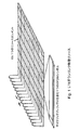
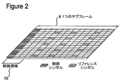
1つのサブキャリア及び1つのOFDMシンボルという単位をリソースエレメント(RE)4といい、図1においてダウンリンク物理リソース2の表現において示されている通りである。よって、1つのPRBは84個のREを含む。図1には、サイクリックプレフィクスを含むOFDMシンボル6もまた示されている。サイクリックプレフィクスは、OFDM信号について、チャネルの時間分散(time dispersion)からの影響を受けにくくする。サイクリックプレフィクスの挿入は、OFDMシンボルの最後の部分を単純にコピーしてOFDMシンボルの冒頭へそれを挿入することにより達成される。LTE無線サブフレームは、図2のダウンリンクサブフレーム8により示されているように、周波数において複数のリソースブロックからなり、そのPRBの数はシステムの帯域幅を左右し、及び時間において2つのスロットからなる。追加的に、時間領域において、LTEダウリンク送信は、10msの無線フレームへと編成され、各無線フレームは、長さTsubframe=1msの等サイズの10個のサブフレームを含む。
A unit of one subcarrier and one OFDM symbol is called a resource element (RE) 4 and is as shown in the representation of the downlink
UEへの無線リンク上で送信されるメッセージは、大まかに、制御メッセージ及びデータメッセージに分類され得る。制御メッセージは、システムの適切な動作及びシステム内の各UEの適切な動作を促進するために使用される。制御メッセージは、UEからの送信電力、及びUEによりデータが受信され又はUEからデータが送信されるべきRBのシグナリングといった機能を制御するためのコマンドを含み得る。 Messages sent on the radio link to the UE can be roughly classified into control messages and data messages. Control messages are used to facilitate proper operation of the system and proper operation of each UE in the system. The control message may include a command for controlling functions such as transmission power from the UE and signaling of an RB from which data is received by the UE or data is to be transmitted from the UE.
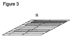
特に3GPP TS36.211、TS36.212、TS36.213への参照を伴う3GPP LTE仕様のリリース8において、構成に依存してサブフレーム内の1番目のOFDMシンボルから4番目のOFDMシンボルまでが、例えば図2の制御領域10により示されているような制御情報を含むものとして予約されている。さらに、3GPP LTE仕様のリリース11において、拡張物理ダウンリンク制御チャネル(EPDCCH)という拡張された制御チャネルが導入され、3GPP LTE仕様のリリース11より以前のリリースのUEへの制御情報を含み得る最初の1〜4個のシンボルはPRBペアから除外されるものの、EPDCCHではPRBペアはEPDCCH送信を排他的に含むように予約される。図3においてこの様子が示されている。図3では、ダウンリンクサブフレーム12は、10個のRBペアと、各々サイズ1のPRBペアであって、横線、縦線及び斜線のストライプで塗りつぶされて示されている3つのEPDCCH領域の構成とを示している。残りのPRBペアは、物理ダウンリンク共有チャネル(PDSCH)送信のために使用され得る。
In particular, in
よって、EPDCCHは、PDSCH送信と時間多重されるPDCCHとは反対に、PDSCH送信と周波数多重される。PDSCH送信のためのリソース割当て(RA)は、ダウンリンク制御情報(DCI)フォーマットに依存して、複数のRAタイプで存在する。いくつかのRAタイプは、リソースブロックグループ(RBG)という最小のスケジューリング粒度を有し得る。RBGは、周波数において隣接するリソースブロックのセットであり、UEをスケジューリングする際、UEは個別のRBではなくRBGを基準にリソースを割当てられる。 Therefore, EPDCCH is frequency-multiplexed with PDSCH transmission, as opposed to PDCCH time-multiplexed with PDSCH transmission. Resource allocation (RA) for PDSCH transmission exists in multiple RA types depending on the downlink control information (DCI) format. Some RA types may have a minimum scheduling granularity of resource block group (RBG). An RBG is a set of resource blocks that are adjacent in frequency, and when scheduling a UE, the UE is assigned resources based on RBGs rather than individual RBs.
ダウンリンク(DL)においてUEがスケジューリングされ、ダウンリンク制御情報(DCI)メッセージがEPDCCHにより搬送される場合、UEは、DL割当てを搬送するPRBペアがリソース割当てから除外されることを前提とするものとされており、即ちレートマッチングが適用される。ここで、レートマッチングは、エンコーダからの出力ビット数が利用可能な物理チャネルビット数に適合することが保証されることを意味する。そのため、この文脈において、DL割当てを搬送するPRBペアは、PDSCH送信のために利用可能な物理チャネルビットを何ら有しない。レートマッチングは、出力ビットから符号化ビットをシステマティックに除去することにより遂行される。どのビットが除去されるかは、送信側及び受信側の双方において既知である。これは、符号チェーンレートマッチングとしても知られている。例えば、サイズが隣接するPRBペア3つであるRBG内のPDSCHにUEがスケジューリングされ、それらPRBペアのうちの1つがDL割当てを含む場合、UEは、このRBG内の残り2つのPRB内でのみPDSCHが送信されることを前提とするものとされる。PDSCHの多重化及びPRBペア内のEPDCCH送信は3GPP LTE仕様のリリース11においてサポートされていないことにも留意されたい。
If the UE is scheduled in the downlink (DL) and the downlink control information (DCI) message is carried on the EPDCCH, the UE assumes that the PRB pair carrying the DL assignment is excluded from the resource assignment That is, rate matching is applied. Here, rate matching means that the number of output bits from the encoder is guaranteed to match the number of available physical channel bits. Thus, in this context, the PRB pair carrying the DL assignment has no physical channel bits available for PDSCH transmission. Rate matching is accomplished by systematically removing coded bits from the output bits. Which bits are removed is known on both the transmitting and receiving sides. This is also known as code chain rate matching. For example, if a UE is scheduled on a PDSCH in an RBG that is three adjacent PRB pairs, and one of those PRB pairs contains a DL assignment, the UE will only be in the remaining two PRBs in this RBG. It is assumed that PDSCH is transmitted. It should also be noted that PDSCH multiplexing and EPDCCH transmission within a PRB pair are not supported in
PDCCH及びEPDCCHは、複数のユーザUEの間で共有される無線リソース上で送信される。各PDCCHは、PDCCHが利用しようとするCCEの数を制御することによりリンク適応を可能とするための、制御チャネルエレメント(CCE)として知られるより小さい部分を含む。PDCCH内のCCEの数は、CCEアグリゲーションレベルと呼ばれ、1、2、4又は8個の連続するCCEの論理シーケンスであり得る。制御領域内の利用可能なCCEの合計数は、物理制御フォーマットインジケータチャネル(PCFICH)構成、システム帯域幅及び構成されるPHICHリソースの数により左右される(図2参照)。各PDCCHは、厳密に1つのDCIを含む。 PDCCH and EPDCCH are transmitted on radio resources shared among a plurality of users UE. Each PDCCH includes a smaller portion known as a control channel element (CCE) to enable link adaptation by controlling the number of CCEs that the PDCCH intends to use. The number of CCEs in the PDCCH is called the CCE aggregation level and may be a logical sequence of 1, 2, 4 or 8 consecutive CCEs. The total number of CCEs available in the control region depends on the physical control format indicator channel (PCFICH) configuration, system bandwidth and the number of configured PHICH resources (see FIG. 2). Each PDCCH contains exactly one DCI.
リソース利用率を改善し、チャネル品質にDCIメッセージの符号レートを適応させるための手段を提供するためには、複数のアグリゲーションレベルが複数のDCIフォーマットをサポートすることを要する。DCIサイズは、フォーマット及びチャネル帯域幅に依存して大きく変化する。様々なアグリゲーションレベルを伴うPDCCHは、“1サイズで全てにフィット(one size fits all)”という解決策の代わりに、リソース利用率の粒度を増加させ得る。ブロードキャスト制御メッセージのリソース割当てについては、より多くの保護を提供するために、より高いアグリゲーションレベルが使用され得る。制御メッセージのためのアグリゲーションレベルは4又は8であり得る一方、UE固有のPDSCH又はPUSCH送信をスケジューリングするDCIメッセージのためのアグリゲーションレベルは1、2、4又は8であり得る。よって、UEは、UE固有のサーチスペースについてCCEの4通りのアグリゲーションレベル、具体的には1、2、4及び8を、共通サーチスペースについてCCEの2通りのアグリゲーションレベル、具体的には4及び8をモニタリングしなければならない。サーチスペースは、UEが自身のPDCCH候補を発見するかもしれない(即ち、サーチ対象である)サブフレーム内の全CCEの合計セットの範囲内のCCEの集合である。 In order to improve resource utilization and provide a means to adapt the code rate of DCI messages to channel quality, multiple aggregation levels need to support multiple DCI formats. The DCI size varies greatly depending on the format and channel bandwidth. PDCCH with different aggregation levels may increase the granularity of resource utilization instead of the “one size fits all” solution. For broadcast control message resource allocation, higher aggregation levels may be used to provide more protection. The aggregation level for control messages may be 4 or 8, while the aggregation level for DCI messages scheduling UE specific PDSCH or PUSCH transmission may be 1, 2, 4 or 8. Thus, the UE has four CCE aggregation levels for UE-specific search spaces, specifically 1, 2, 4 and 8, and two CCE aggregation levels for common search space, specifically 4 and 8 must be monitored. A search space is a collection of CCEs within the total set of all CCEs in a subframe in which the UE may find its PDCCH candidate (ie, the search target).
2008年からの3GPP技術仕様36.213“Physical Layer Procedures, Release 8”は、セクション9.1.1において、アグリゲーションレベルL∈{1,2,4,8}でのサーチスペースSk (L)を説明しており、これは次式により与えられるCCEの連続的なセットにより定義される:
The 3GPP technical specification 36.213 “Physical Layer Procedures,
ここで、NCCE,kはサブフレームkの制御領域内のCCEの合計数であり、Zk (L)はサーチスペースの開始を定義し、i=0,1,…,M(L)・L−1であり、M(L)は所与のサーチスペース内でモニタリングすべきPDCCHの数である。各CCEは、36個のQPSK変調シンボルを含む。M(L)の値は、3GPP技術仕様36.213“Physical Layer Procedures (Release 8)”内のテーブル9.1.1−1により仕様化されており、以下に転載される。 Where N CCE, k is the total number of CCEs in the control region of subframe k, Z k (L) defines the start of the search space, and i = 0, 1,..., M (L) · L-1 and M (L) is the number of PDCCHs to monitor in a given search space. Each CCE includes 36 QPSK modulation symbols. The value of M (L) is specified by the table 9.1.1-1 in the 3GPP technical specification 36.213 “Physical Layer Procedures (Release 8)”, and is reprinted below.
この定義では、システム帯域幅に関わらず、異なるアグリゲーションレベルについてのサーチスペースが互いに重複し得る。より具体的には、UE固有のサーチスペースと共通サーチスペースとが重複するかもしれず、及び、異なる複数のアグリゲーションレベルについてのサーチスペースが重複するかもしれない。以下の、合計でCCEは9つであり、PDCCH候補の間の非常に頻繁な重複が存在する1つの例を参照されたい。 With this definition, search spaces for different aggregation levels can overlap each other regardless of system bandwidth. More specifically, the UE-specific search space and the common search space may overlap, and the search spaces for different aggregation levels may overlap. See the example below, which has a total of 9 CCEs and there is very frequent overlap between PDCCH candidates.
PDCCHと同様に、EPDCCHは複数のUEにより共有される無線リソース上で送信され、拡張CCE(eCCE)がPDCCHのためのCCEに等価なものとして導入される。eCCEは、固定数のREをも有し、但しEPDCCHマッピングのために利用可能なREの数は概してこの固定数よりも少なく、なぜなら多くのREがセル固有リファレンス信号(CRS)及びチャネル状態情報リファレンス信号(CSI−RS)といった他の信号により占められるからである。符号チェーンのレートマッチングは、あるeCCEに属するREが他の衝突する信号を含む度ごとに適用され、他の衝突する信号とは、CRS、CSI−RS、レガシー制御領域、又は時間分割複信(TDD)のケースではガードピリオド(GP)及びアップリンクパイロット時間スロット(UpPTS)などである。よって、衝突する信号により占められるREは、EPDCCHにとって利用可能な物理チャネルビットに属しない。 Similar to PDCCH, EPDCCH is transmitted on radio resources shared by multiple UEs, and enhanced CCE (eCCE) is introduced as equivalent to CCE for PDCCH. The eCCE also has a fixed number of REs, but the number of REs available for EPDCCH mapping is generally less than this fixed number because many REs are cell specific reference signals (CRS) and channel state information references. This is because it is occupied by another signal such as a signal (CSI-RS). The rate matching of the code chain is applied every time an RE belonging to an eCCE includes another colliding signal, which includes CRS, CSI-RS, legacy control region, or time division duplex ( In the case of TDD), such as a guard period (GP) and an uplink pilot time slot (UpPTS). Thus, the RE occupied by the colliding signals does not belong to the physical channel bits available for the EPDCCH.
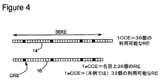
図4における例を考慮されたい。そこでは、CCEが常にTavail=36個の利用可能なREを含むようにCRSを回避しているPDCCHマッピングを、アイテム14が例示している。アイテム16では、どのようにeCCEが名目上で36個のREを含むかが示されているが、衝突する信号が存在する場合には利用可能なREの数はより少なく、よってEPDCCHについてTavail≦36REである。衝突する信号はサブフレーム依存であることから、Tavailの値もまたサブフレーム依存になり、衝突がeCCEに不均等に影響する場合には異なるeCCEについてTavailの値が異なることさえあり得る。なお、PRBペアごとのeCCEの数が2つである場合(いつこれが生じるかについては以下のテーブル3参照)、eCCEごとのREの名目上の数は36個ではなく、その代わりに、通常及び拡張サイクリックプレフィクス(CP)についてそれぞれ72個又は64個である。
Consider the example in FIG. There, a PDCCH mapping avoids the CRS to CCE including always T avail = 36 pieces available RE,
3GPP LTE仕様のリリース11において、EPDCCHは、UE固有のサーチスペースのみをサポートする一方で、共通サーチスペースは依然として同じサブフレーム内のPDCCHにおいてモニタリングされることになる。将来のリリースでは、EPDCCH送信についても共通サーチスペースが導入され得る。以下のテーブル2に示した制限を伴って、UEはeCCEのアグリゲーションレベル1、2、4、8、16及び32をモニタリングするように仕様化されており、ここでnEPDCCHは、PRBペアにおけるEPDCCH送信にとって利用可能なREの数である。様々なアグリゲーションレベルはEPDCCHフォーマット0、1、2、3及び4として付番されている。テーブル2において、分配され(distributed)及び局所化される(localized)送信信号とは、リソースエレメントへのEPDCCHのマッピングをいう。
In
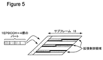
分配される送信において、EPDCCHは、D=2、4又は8としてD個のPRBペアまでのリソースエレメントへとマッピングされてよく、D=16という値もまた考慮され得る。この手法で、EPDCCHメッセージについて周波数ダイバーシティが達成され得る。図5は、ダウンリンクサブフレーム18がEPDCCHに属する4つの部分を示す概略的な例であり、それはPRBペアとして知られる多様な拡張制御領域へとマッピングされ、分散的な送信と周波数ダイバーシティ又はサブバンドプリコーディングとが達成される。 In a distributed transmission, the EPDCCH may be mapped to resource elements up to D PRB pairs as D = 2, 4 or 8, and a value of D = 16 may also be considered. In this manner, frequency diversity can be achieved for EPDCCH messages. FIG. 5 is a schematic example showing the four parts where the downlink subframe 18 belongs to the EPDCCH, which is mapped into various extended control regions known as PRB pairs, and is distributed transmission and frequency diversity or sub- Band precoding is achieved.
局所化される送信において、EPDCCHは、スペースが許すならば1つのPRBペアのみへとマッピングされる(これは、アグリゲーションレベル1及び2については常に可能であり、レベル4についても通常サブフレームかつ通常CP長なら可能である)。EPDCCHのアグリゲーションレベルが大き過ぎるケースでは、EPDCCHに属する全てのCCEがマッピング済みとなるまで、より多くのPRBペアを用いて、第2のPRBペアもまた使用されるなどする。1つのPRBペアにフィットするeCCE数は、以下のテーブル3により与えられる。
In localized transmissions, the EPDCCH is mapped to only one PRB pair if space allows (this is always possible for
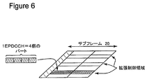
図6は、局所化される送信の様子を示している。図6において、ダウンリンクサブフレーム20は、4つのeCCEがEPDCCHに属しており局所化された送信を達成するために拡張制御領域の1つへとマッピングされていることを示している。 FIG. 6 shows a state of transmission to be localized. In FIG. 6, downlink subframe 20 shows that four eCCEs belong to EPDCCH and are mapped to one of the extended control regions in order to achieve localized transmission.
一例として、通常サブフレームにおいて、通常CP長であってnEPDCCH≧104である場合、局所化される送信は、アグリゲーションレベル{1,2,4,8}を使用しており、それぞれ{1,1,1,2}個のPRBペアへマッピングされる。 As an example, in a normal subframe, if the normal CP length and n EPDCCH ≧ 104, the localized transmission uses the aggregation level {1, 2, 4, 8}, respectively, Maps to 1,1,2} PRB pairs.
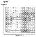
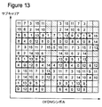
eCCEの物理リソースへのマッピングを容易化するために、各PRBペアは16個の拡張リソースエレメントグループ(eREG)へ分割され、各eCCEは通常及び拡張サイクリックプレフィクスについてそれぞれ4又は8個のeREGへとスプリットされる。EPDCCHは、結果として、アグリゲーションレベルに依存して、4又は8の倍数個のeREGへとマッピングされる。ePDCCHに属するこれらeREGは、局所化される送信にとって典型的であるように単一のPRBペアに所在するか、又は分配される送信にとって典型的であるように複数のPRBペアに所在するか、のいずれかである。PRBペアのeREGへの厳密な分割は、様々な手法で実行されてよい。PRBペアのeREGへの分割の1つの例が図7に示されている。 To facilitate mapping of eCCEs to physical resources, each PRB pair is divided into 16 extended resource element groups (eREGs), each eCCE being 4 or 8 eREGs for normal and extended cyclic prefixes, respectively. Is split. The EPDCCH is consequently mapped to a multiple of 4 or 8 eREGs, depending on the aggregation level. These eREGs belonging to the ePDCCH are located in a single PRB pair as is typical for localized transmissions, or are located in multiple PRB pairs as are typical for distributed transmissions, One of them. The exact division of the PRB pair into eREGs may be performed in various ways. One example of splitting a PRB pair into eREGs is shown in FIG.
図7は、通常サブフレームにおける通常サイクリックプレフィクス構成のPRBペアを示している。各タイルはリソースエレメントであり、数字はリソースエレメントをグループ化するeREGに対応する。右傾した対角線の縞模様のタイルは0というインデックスが与えられる第1のeREGに対応する。左傾した対角線の縞模様のタイルは、復調リファレンス信号(DMRS)を含む。 FIG. 7 shows a PRB pair having a normal cyclic prefix configuration in a normal subframe. Each tile is a resource element, and the number corresponds to an eREG that groups the resource elements. Diagonal striped tiles tilted to the right correspond to the first eREG given an index of zero. The diagonally striped tile tilted to the left contains a demodulated reference signal (DMRS).
3GPP標準に関しては、4又は8個のeREGをそれぞれいかにeCCEへとグループ化するかについて3GPP内で未だ合意はなされていない。EPDCCHメッセージの符号化され変調されたシンボルをその関連付けられるeREGにより予約されるリソース内のREへといかにマッピングするかについても問題は未解決である。追加的に、EPDCCHについてのアグリゲーションレベルごとのブラインド復号の回数は3GPP標準化作業において未決定である。同様に、PDCCHでそうであったようにEPDCCHについても異なるアグリゲーションレベルのEPDCCH候補の間の重複が生じることになるが、局所化されるマッピング及び分配されるマッピングについてサーチスペースのランダム化をいかに生成するかは未決定である。
Regarding the 3GPP standard, no agreement has yet been reached within 3GPP on how to
PDCCH及びEPDCCH送信は、レート1/3テールバイティング畳み込み符号のための、循環バッファに基づくレートマッチングを採用する。符号化ビットの反復及び異なるアグリゲーションレベルの間のサーチスペースの重複に起因して、複数のアグリゲーションレベルが巡回冗長検査(CRC)を通過するかもしれず、これがPDCCHのケースについてここで説明されるであろう。当該ケースでは、CCEごとの利用可能なREの数は常にTavail=36個である。
PDCCH and EPDCCH transmissions employ rate matching based on circular buffers for
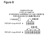
循環バッファに基づくレートマッチングに起因して、所与のPDCCHアグリゲーションサイズ(2、4又は8)について、符号化ビットは、第1のCCEの後に自己反復を開始する。図8には、具体的なペイロードサイズ(48ビット)についての一例が与えられている。図8において、アグリゲーションサイズ8では4回の反復が存在し、各反復は循環バッファ内の同じ位置で開始することを見ることができる。
Due to rate matching based on a circular buffer, for a given PDCCH aggregation size (2, 4 or 8), the coded bits start self-repetition after the first CCE. In FIG. 8, an example of a specific payload size (48 bits) is given. In FIG. 8, it can be seen that at
概して、レベルの混同を有することになる必要条件は、等式(2)において以下に示したように表現され得る。
3×N×k=2×Tavail×m (2)
ここで、Nは曖昧性のあるペイロードサイズであり、m及びkは共に整数である。PDCCHについて、CCE別の変調シンボル数は、上で議論したように、Tavail=36個であり得る。よって、PDCCHについて、等式(2)を以下の等式(2´)に示したように簡略化し得る。
N×k=24×m (2´)
In general, a requirement that would have a level of confusion can be expressed as shown below in equation (2).
3 × N × k = 2 × T avail × m (2)
Here, N is an ambiguous payload size, and m and k are both integers. For the PDCCH, the number of modulation symbols per CCE may be T avail = 36 as discussed above. Thus, for PDCCH, equation (2) can be simplified as shown in equation (2 ′) below.
N × k = 24 × m (2 ′)
なお、UEは0.8よりも大きい符号レートでPDCCHを復号することを要請されないために、Nは、58×(8−m)以下であるべきである。例えば、N=48である場合、m=2kであり、kは値1、2又は4をとり得る。{1,2,4,8}の任意の組合せが2つ以上のアグリゲーションレベルの混同を生じさせ得る。LTE PDCCHペイロードは、情報ビットと対応する16ビットの巡回冗長検査(CRC)とを含み、ペイロードサイズは12ビット以上である。CRCビットは、ペイロードビットの関数であり、検出されるペイロードが正しいかを高確率で検証する可能性を受信機に提供する。そこで、LTEシステムでのPDCCH送信に当てはまる全ての問題となるペイロードサイズの網羅的なリストが以下のセット(3)に示される。
{12,14,16,20,24,26,32,40,44,56} (3)
Note that N should be less than or equal to 58 × (8−m) because the UE is not required to decode PDCCH at a code rate greater than 0.8. For example, if N = 48, m = 2k, and k can take the
{12, 14, 16, 20, 24, 26, 32, 40, 44, 56} (3)
PDCCHにおける符号化ビットの反復と、異なるアグリゲーションサイズの間のサーチスペースの重複とに起因して、複数のアグリゲーションサイズがCRCのチェックを通過し得る。PDCCHの最初のCCEはダイナミックスケジューリングのためのアップリンクACK/NACKリソースにリンク付けされることから、UEは、eNBに知られていない異なるリソースでそのACK/NACKを送信するかもしれず、複数のACK/NACKリソースがあり得る。このようにして、異なるアグリゲーションレベルからの2つ以上のPDCCH復号候補が異なる最小CCEインデックスを有する場合に、対応するPDCCHグラントの、最初のCCEからマッピングされるアップリンク(UL)ACK/NAKリソースの位置における混同が存在し得る。潜在的に間違っているUL ACK/NAKリソース位置は、不必要なUL干渉を生じさせるだけでなく、特に高ジオメトリUEについて、ダウンリンクのスループットにも影響を与えかねない。高ジオメトリUEとは、高い信号対干渉比を伴うなどのように、良好なチャネル品質を伴うUEである。PDCCHについてのこの問題を回避するために、(本明細書での実施形態に関しない)1つの提案済みの解決策は、DCIフォーマットペイロードがセット(3)にリスト化されたペイロードのうちの1つに属さなくなるまで、ペイロードへ1つ以上のゼロビットを付加(append)することを含む。 Multiple aggregation sizes may pass the CRC check due to repetition of coded bits in the PDCCH and search space overlap between different aggregation sizes. Since the first CCE of the PDCCH is linked to an uplink ACK / NACK resource for dynamic scheduling, the UE may send its ACK / NACK on different resources not known to the eNB, and multiple ACKs There may be a / NACK resource. In this way, if two or more PDCCH decoding candidates from different aggregation levels have different minimum CCE indices, the uplink (UL) ACK / NAK resources mapped from the first CCE of the corresponding PDCCH grant. There can be confusion in location. Potentially incorrect UL ACK / NAK resource locations not only cause unnecessary UL interference, but may also affect downlink throughput, especially for high geometry UEs. A high geometry UE is a UE with good channel quality, such as with a high signal-to-interference ratio. To avoid this problem for PDCCH, one proposed solution (not related to the embodiments herein) is one of the payloads whose DCI format payload is listed in set (3). Including appending one or more zero bits to the payload until it does not belong.
問題のあるペイロードサイズに伴う課題は、EPDCCH送信についても存在する。しかしながら、eCCEごとの利用可能なREの数であるTavailは固定数でもなければ異なるサブフレームにわたって一定でもないことから、3GPP技術仕様36.212“Multiplexing and channel coding”のテーブル5.3.3.1.2−1の、問題のあるペイロードサイズを識別するという解決策は扱いにくくなる。なぜなら、Tavailのあり得る値の各々について、問題のあるペイロードサイズの1つのセットが必要とされるからである。さらに、異なるeCCEは異なる数の利用可能なREを有するかもしれず、これはなお一層、問題のあるペイロードサイズでの解決策への興味を低下させる。 Problems with problematic payload sizes also exist for EPDCCH transmission. However, since T avail , the number of REs available per eCCE, is neither a fixed number nor constant across different subframes, table 5.3.3 of 3GPP Technical Specification 36.212 “Multiplexing and channel coding” The solution of 1.2-1. Identifying problematic payload sizes becomes cumbersome. This is because for each possible value of T avail , one set of problematic payload sizes is required. Furthermore, different eCCEs may have different numbers of available REs, which further diminishes interest in solutions with problematic payload sizes.
これは、PDCCHについて解決策が見出される前に3GPP LTE仕様のリリース8について存在していたものと同じUL ACK/NACKの混乱の問題を招く。なぜなら、EPDCCH送信についても、関連するUL ACK/NACKリソースは、関連するDL割当ての最初のeCCEのインデックスの関数だからである。加えて、これは、実際に送信されたEPDCCHメッセージのアグリゲーションレベルよりも正確に検出されたEPDCCHのアグリゲーションレベルが小さい場合に、PDSCHリソース割当ての曖昧性の問題を招き、それにより、DL割当てについて実際に使用されたものよりも少ないPRBペアがUEにより想定されることになる。
This leads to the same UL ACK / NACK confusion problem that existed for
UEは、DL割当てのEPDCCH送信のために使用されないスケジューリングされたPRBペアは対応するPDSCH送信を含むであろうと想定する。UEがより小さいアグリゲーションレベルでEPDCCHを検出した場合、いくつかのケースでは、実際に使用されたものよりも少ないPRBペアしかEPDCCHについて使用されないとUEが想定することが起こり得る。これらのケースでは、UEは、PDSCH送信が含まれることを想定することになるが、そのPDSCHの受信は失敗するであろう。 The UE assumes that scheduled PRB pairs that are not used for DL-assigned EPDCCH transmissions will contain corresponding PDSCH transmissions. If the UE detects an EPDCCH at a lower aggregation level, in some cases it may happen that the UE assumes that fewer PRB pairs are used for the EPDCCH than was actually used. In these cases, the UE will assume that PDSCH transmission is included, but reception of that PDSCH will fail.
従って、ここでの実施形態の目的は、上述した課題を最小化し及び/又は回避する、LTEシステムでの通信を改善する手法を提供することである。 Accordingly, the purpose of the embodiments herein is to provide a technique for improving communication in an LTE system that minimizes and / or avoids the problems described above.
ここでの実施形態の第1の観点によれば、上記目的は、拡張物理ダウンリンク制御チャネル(EPDCCH)メッセージのシンボルをマッピングするための、通信ノードにおける方法により達成される。上記EPDCCHは、1つ以上のアグリゲーションレベルを含む。各アグリゲーションレベルについて、EPDCCHメッセージは、制御チャネルエレメント(eCCE)のセットにより構成される。各eCCEは、複数の拡張リソースエレメントグループ(eREG)のセットへとマッピングされ、各eREGは、物理リソースブロック(PRB)ペア内のリソースエレメント(RE)のグループである。上記通信ノードは、EPDCCHメッセージの上記シンボルを、上記eCCEのセットに対応する上記複数のeREGを構成する上記REのセットへとマッピングする。上記EPDCCHシンボルが上記REのセットへとマッピングされる順序は、上記アグリゲーションレベルに依存する。 According to a first aspect of the present embodiment, the above objective is achieved by a method in a communication node for mapping symbols of an enhanced physical downlink control channel (EPDCCH) message. The EPDCCH includes one or more aggregation levels. For each aggregation level, the EPDCCH message is composed of a set of control channel elements (eCCE). Each eCCE is mapped to a set of multiple extended resource element groups (eREGs), and each eREG is a group of resource elements (RE) in a physical resource block (PRB) pair. The communication node maps the symbol of the EPDCCH message to the set of REs constituting the plurality of eREGs corresponding to the set of eCCEs. The order in which the EPDCCH symbols are mapped to the set of REs depends on the aggregation level.
ここでの実施形態の第2の観点によれば、上記目的は、拡張物理ダウンリンク制御チャネル(EPDCCH)メッセージのシンボルをマッピングするための通信ノードにより達成される。上記EPDCCHは、1つ以上のアグリゲーションレベルを含む。各アグリゲーションレベルについて、EPDCCHメッセージは、制御チャネルエレメント(eCCE)のセットにより構成される。各eCCEは、複数の拡張リソースエレメントグループ(eREG)のセットへとマッピングされ、各eREGは、物理リソースブロック(PRB)ペア内のリソースエレメント(RE)のグループである。上記通信ノードは、EPDCCHメッセージの上記シンボルを、上記eCCEのセットに対応する上記複数のeREGを構成する上記REのセットへとマッピングするように構成されるチャネル符号化回路を含む。上記EPDCCHシンボルが上記REのセットへとマッピングされる順序は、上記アグリゲーションレベルに依存する。 According to a second aspect of the present embodiment, the above object is achieved by a communication node for mapping symbols of an enhanced physical downlink control channel (EPDCCH) message. The EPDCCH includes one or more aggregation levels. For each aggregation level, the EPDCCH message is composed of a set of control channel elements (eCCE). Each eCCE is mapped to a set of multiple extended resource element groups (eREGs), and each eREG is a group of resource elements (RE) in a physical resource block (PRB) pair. The communication node includes a channel coding circuit configured to map the symbols of the EPDCCH message to the set of REs constituting the plurality of eREGs corresponding to the set of eCCEs. The order in which the EPDCCH symbols are mapped to the set of REs depends on the aggregation level.
EPDCCHメッセージにおいてアグリゲーションレベルが示されることから、不必要なUL干渉を生み出し及びダウンリンクスループットに悪影響を与える、UEによるアグリゲーションレベルの誤解釈を原因とする潜在的なUL ACK/NAKリソース位置の間違いを回避することができる。これは、LTEシステムにおける改善された通信に帰結する。 Since the aggregation level is indicated in the EPDCCH message, the potential UL ACK / NAK resource location error due to misinterpretation of the aggregation level by the UE that creates unnecessary UL interference and adversely affects downlink throughput. It can be avoided. This results in improved communication in the LTE system.
本明細書における実施形態の利点は、大きいアグリゲーションレベルでEPDCCHからスケジューリングされる場合のPDSCHの受信失敗の問題が除去されることである。 An advantage of the embodiments herein is that the problem of PDSCH reception failure when scheduling from the EPDCCH at a large aggregation level is eliminated.
添付図面は、本発明の例示的な実施形態を次の通り示す: The accompanying drawings illustrate exemplary embodiments of the invention as follows:
本発明の以下の詳細な説明は、添付図面を参照する。異なる図面中の同じ参照番号は、同じ又は同様のエレメントを識別する。また、以下の詳細な説明は、本発明を限定しない。 The following detailed description of the invention refers to the accompanying drawings. The same reference numbers in different drawings identify the same or similar elements. Also, the following detailed description does not limit the invention.
LTE(Long Term Evolution)では、リリース11において、拡張物理ダウンリンク制御チャネル(EPDCCH)として知られる拡張制御チャネルが導入された。EPDCCHは、Nを変数としてN個の拡張制御チャネルエレメント(eCCE)の集合体を含む。EPDCCHエンコーダの構造に起因して、UEは、ある状況下で、実際に使用されるN個のeCCEよりも少ないeCCEを用いてしか正確にEPDCCHを検出しないかもしれない。これは、潜在的な2つの問題を招き得る:(1)HARQ−ACKリソースがユーザ機器(UE)により間違って選択され、どのリソースが使用されるかについてeNBとUEとの間で誤解が存在することになる;(2)EPDCCH送信のために使用されるべきPRBペアが、代わりに物理ダウンリンク共有チャネル(PDSCH)送信のために使用されるというように、UEが誤った前提をおくことになり、PDSCHの受信エラーがもたらされる。
In Long Term Evolution (LTE),
ここでの例示的な実施形態によれば、これら問題は、UEが受信されるEPDCCH送信信号の使用されるアグリゲーションレベルを検出するための手段を取り入れることにより解決され得る。UEは、アグリゲーションレベルの検出を意図的に試行しなくてもよいが、UEがEPDCCHを検出した場合には、そのアグリゲーションレベルもまた何らの曖昧性なく知得されるという結果となる。この手法で、UEは、送信についてどのアグリゲーションレベルが使用されたかにおける曖昧性無く、EPDCCHを検出し得る。これは、アップリンク(UL)のACK/NACKリソースを正確に得るために、最初のeCCEインデックスが正確に取得されることを保証し得る。さらに、ここでの例示的な実施形態は、EPDCCH送信を含むPRBペアがPDSCH送信を含んでいることについて混乱が無いことを保証する。 According to an exemplary embodiment here, these problems can be solved by incorporating means for detecting the used aggregation level of the EPDCCH transmission signal received by the UE. The UE may not intentionally attempt to detect the aggregation level, but if the UE detects the EPDCCH, the result is that the aggregation level is also known without any ambiguity. In this manner, the UE may detect the EPDCCH without ambiguity as to which aggregation level was used for transmission. This may ensure that the initial eCCE index is obtained correctly in order to accurately obtain uplink (UL) ACK / NACK resources. Furthermore, the exemplary embodiment here ensures that there is no confusion about PRB pairs containing EPDCCH transmissions including PDSCH transmissions.
これを達成するための手法は、eCCEのセットに対応する複数のeREGを構成するREのセットへEPDCCHメッセージのシンボルをマッピングする、EPDCCH固有の手法及びアグリゲーションレベル固有の手法を取り入れることであり、その中で、EPDCCHシンボルをREのセットへマッピングする順序はアグリゲーションレベルに依存する。eCCEは、物理レイヤにおけるREのOFDM時間周波数グリッドにおいて定義される、4又は8のeREGのグループとして定義される。例えば、eCCE#0は、eREG0、4、8及び12を含み得る。そして、各eREGは、PRBペアの範囲内のREの特定のグループからなる。ePDCCHは、1つ又は複数のeCCEを含んでよく、よってEPDCCHを構成するeCCEのセットは、物理レイヤにおいて複数のeREGに対応する。
A technique for achieving this is to adopt an EPDCCH-specific technique and an aggregation level-specific technique for mapping the symbols of an EPDCCH message to a set of REs that constitute a plurality of eREGs corresponding to the set of eCCEs. Among them, the order in which EPDCCH symbols are mapped to RE sets depends on the aggregation level. An eCCE is defined as a group of 4 or 8 eREGs defined in the OFDM OFDM time frequency grid in the physical layer. For example,
これを達成するための他の手法は、EPDCCH固有及びアグリゲーションレベル固有のEPDCCHのスクランブリングを取り入れることである。UEが正確なスクランブリングシーケンス、即ち正確なアグリゲーションレベルを想定しない場合には、EPDCCHの検出は失敗することになる。 Another approach to accomplish this is to incorporate EPDCCH specific and aggregation level specific EPDCCH scrambling. If the UE does not assume the correct scrambling sequence, ie the correct aggregation level, EPDCCH detection will fail.
例示的な実施形態によれば、LTE通信システムにおけるEPDCCHの検出エラーを除去するためのシステム及び方法が存在する。情報ビットを含むEPDCCHペイロード及び付加されるCRCビットは、送信用の符号化ビットシーケンスを生成するために符号化され得る。符号化ビットは、循環バッファへと入力され得る。 According to an exemplary embodiment, there is a system and method for eliminating EPDCCH detection errors in an LTE communication system. The EPDCCH payload including the information bits and the appended CRC bits can be encoded to generate a coded bit sequence for transmission. The encoded bits can be input into a circular buffer.
図9は、ここでの実施形態が実装され得る無線通信システム100を描いている。無線通信システム100は、LTEシステムなどの無線通信ネットワークである。 FIG. 9 depicts a wireless communication system 100 in which embodiments herein can be implemented. The wireless communication system 100 is a wireless communication network such as an LTE system.
無線通信システム100は、1つ以上のセルを含む。図9において、通信ノード110は、セル115へサービスを提供している。通信ノード110は、eNodeB、略してeNBであってもよく、又は例えばLTEシステムに関連付けられるリレーノードといった他の送信ノードであってもよい。
The wireless communication system 100 includes one or more cells. In FIG. 9, the
ユーザ機器(UE)120は、セル115内に位置する。UE120は、例えば、携帯電話、例えばラップトップ、PDA(Personal Digital Assistant)若しくはサーフプレートと呼ばれることもあるタブレットコンピュータといった無線ケイパビリティを伴うコンピュータ、又は、無線通信システム100において通信ノード110との間で無線リンク上で通信可能な何らかの他の無線ネットワークユニットであってよい。また、UE120は、リレーノードであってもよい。
User equipment (UE) 120 is located in cell 115. The
次に、拡張物理ダウンリンク制御チャネル(EPDCCH)メッセージのシンボルをマッピングするための、通信ノード110における方法の例示的な実施形態について、図10に描いたフローチャートを参照しながら説明する。通信ノード110は、eNodeB、略してeNB、又はリレーノードであってよい。EPDCCHは、1つ以上のアグリゲーションレベルを含み、各アグリゲーションレベルについて、EPDCCHメッセージは、eCCEのセットにより構成される。各eCCEは、複数のeREGのセットへとマッピングされ、各eREGは、1つのPRBペア内のREのグループである。本方法は、以下のアクション群を含み、それらアクションは、任意の適した順序で行われてよい。ここで説明される方法のアクションは、一般的な形で記述されており、後により詳細に説明されるであろう。アクション1001〜1006及び1008〜1009は、例示的な実施形態に係るオプションとしてのアクションである。オプションとしてのアクションは、図10において破線のボックスで示されている。
Next, an exemplary embodiment of a method at
[アクション1001]例示的なシナリオにおいて、通信ノード110は、UE120へ送信されるべきEPDCCHペイロードビットを受け取っている。通信ノード110は、符号化の前にCRCビットを付加し得る。CRCビットは、ペイロードビットの関数である。いくつかの実施形態によれば、全体的なPDCCHペイロードがCRCパリティビット”を計算するために使用される。PDCCHペイロードのビット群はa0,a1,a2,a3,…aA−1により表記され、パリティビットはp0,p1,p2,p3,…pL−1により表記される。AはPDCCHペイロードサイズであり、Lはパリティビット数である。
[Action 1001] In an exemplary scenario, the
セクション5.1.1に従い、Lを16ビットに設定してパリティビットが計算され及び付加され、B=A+Lとして、シーケンスb0,b1,b2,b3,…bB−1が導出される。
Accordance with Section 5.1.1, the parity bit is being and added calculated by setting L to 16 bits, as B = A + L, the sequence b 0, b 1, b 2 ,
[アクション1002]通信ノード110は、EPDCCHペイロードビット及び付加されたCRCビットを、符号化ビットへと、符号化ビットの3つの出力パリティストリームへと符号化する。これは、符号化ビットシーケンスを生成するためである。
[Action 1002] The
[アクション1003]いくつかの実施形態において、通信ノード110は、複数の出力シーケンスの各々をインターリーブする。これは、チャネル符号の性能を改善するためである。
[Action 1003] In some embodiments, the
[アクション1004]いくつかの実施形態において、通信ノード110は、出力シーケンスをバッファへと収集する。バッファは、循環バッファであってよい。これは、次のステップでの効果的なレートマッチングを提供するためであり、物理チャネルビット数が符号化ビット数よりも多い場合に加えてより少ないケースをカバーする。
[Action 1004] In some embodiments, the
[アクション1005]通信ノード110は、EPDCCHへ割当てられる物理チャネルビットの数に適合するように、複数の出力シーケンスを読み取り得る。これは、符号化ビットと物理チャネルビットとの間の1対1のマッピングが存在することを保証するための、符号チェーンレートマッチングである。
[Action 1005] The
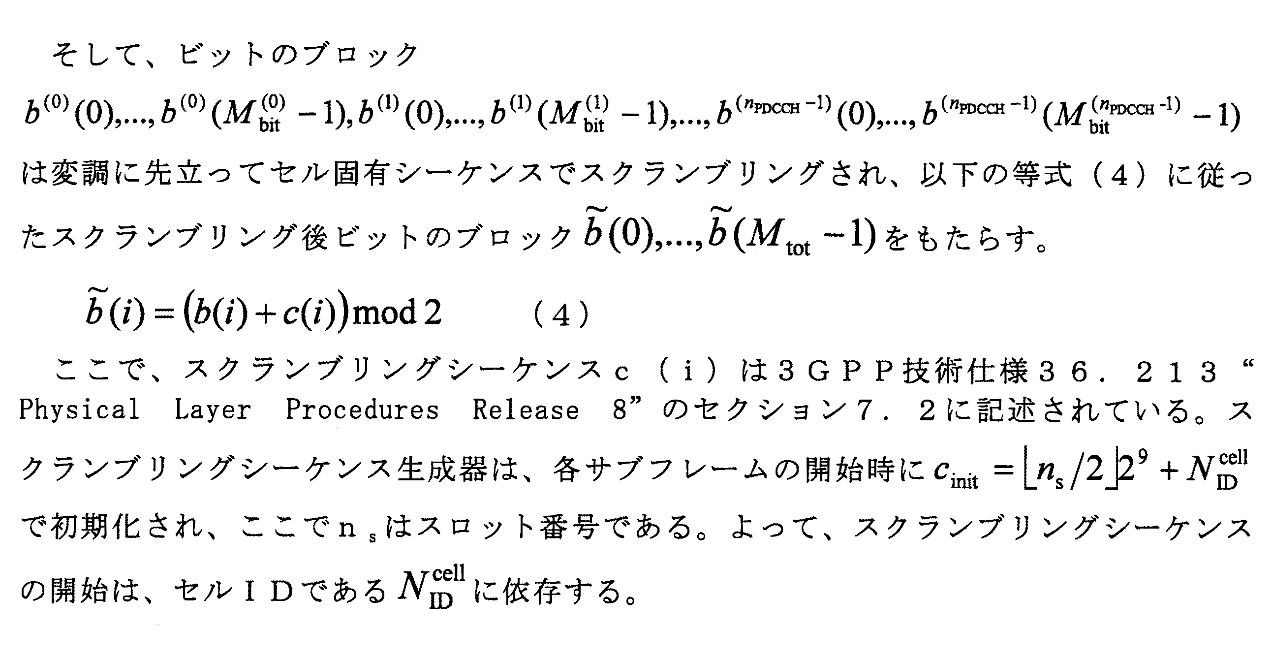
[アクション1006]通信ノード110は、ビットの出力シーケンスをスクランブリングし得る。これは、隣接セルからのPDCCHをUE120等のUEが検出してしまう確率を引き下げるためであり、異なるセル又は通信ノード110等のeNBに、異なるスクランブリングシーケンスを割当てることにより達成される。
[Action 1006] The
[アクション1007]
ここでの実施形態によれば、通信ノード110は、EPDCCHメッセージのシンボルを、eCCEのセットに対応する複数のeREGを構成するREのセットへとマッピングする。EPDCCHシンボルがREのセットへとマッピングされる順序は、アグリゲーションレベルに依存する。これは、アグリゲーションレベルの暗黙的な標識となるEPDCCHメッセージに帰結する。UE120がその標識を伴うEPDCCHメッセージを受信する場合、アグリゲーションレベルのいかなる誤解釈も回避される。
[Action 1007]
According to the present embodiment, the
マッピングは、EPDCCHシンボルを、複数のPRBペアのEPDCCHセットの割当てられるeREGにわたって、例えば割当てられる全てのeREGにわたってサブキャリア優先方式(subcarrier-first fashion)でマッピングし、次に時間にわたってマッピングすることにより、実行されてもよい。 The mapping is by mapping EPDCCH symbols across assigned eREGs of EPDCCH sets of multiple PRB pairs, eg, in a subcarrier-first fashion across all assigned eREGs, and then over time. May be executed.
時間(この文脈ではOFDMシンボル)が一方の次元であり、周波数(この文脈ではサブキャリア)が他方の次元である2次元のリソースグリッドにおいて、サブキャリア優先方式でのマッピングが意味するのは、メッセージが、まずは、第1のOFDMシンボル内の複数のサブキャリアにわたって時間上の当該第1のOFDMシンボルへマッピングされ、続いて、第2のOFDMシンボル内の複数のサブキャリアにわたって当該第2のOFDMシンボル内でマッピングされる、などといったことである。 In a two-dimensional resource grid where time (OFDM symbol in this context) is one dimension and frequency (subcarrier in this context) is the other dimension, mapping in a subcarrier priority scheme means message Are first mapped to the first OFDM symbol over time over a plurality of subcarriers within the first OFDM symbol, and then over the plurality of subcarriers within the second OFDM symbol. And so on.
いくつかの実施形態において、通信ノード110は、EPDCCHシンボルを、各PRBペアの範囲内の割当てられるeREGにわたって、サブキャリア優先方式でマッピングし、次に時間にわたってマッピングし、次にEPDCCHセット内の複数のPRBペアにわたってマッピングする、ことによりEPDCCHメッセージのシンボルをREのセットへとマッピングする。
In some embodiments, the
いくつかの代替的な実施形態において、通信ノード110は、EPDCCHシンボルを、EPDCCHセットに属する全てのPRBペアにわたって、即ちEPDCCHセットに属する全てのPRBペア内の割当てられるeREGにわたって、サブキャリア優先方式でマッピングし、次に時間にわたってマッピングする、ことによりEPDCCHメッセージのシンボルをREのセットへとマッピングする。
In some alternative embodiments, the
異なるマッピング手法が後により詳細に説明されるであろう。 Different mapping techniques will be described in more detail later.
[アクション1008]
これはオプションとしてのアクションである。通信ノード110は、EPDCCHメッセージのアグリゲーションレベル固有のスクランブリングを実行し得る。
[Action 1008]
This is an optional action. The
いくつかの実施形態において、通信ノード110は、1つ以上のビットを含む等サイズ又は別サイズのビットチャンク(chunks of bits)へと符号化ビットをグループ化し、アグリゲーションレベルに依存する順序でビットチャンクを並び替えることにより、EPDCCHメッセージのアグリゲーションレベル固有のスクランブリングを実行する。
In some embodiments, the
いくつかの実施形態において、通信ノード110は、1つ以上のシンボルを含む等サイズ又は別サイズのシンボルチャンク(chunks of symbols)へと変調EPDCCHシンボルをグループ化し、アグリゲーションレベルに依存する順序でチャンクを並び替えることにより、EPDCCHメッセージのアグリゲーションレベル固有のスクランブリングを実行する。
In some embodiments, the
いくつかの実施形態において、通信ノード110は、EPDCCHの各DCIメッセージを、その対応するアグリゲーションレベル固有のスクランブリングシーケンスでスクランブリングすることにより、EPDCCHメッセージのアグリゲーションレベル固有のスクランブリングを実行する。
In some embodiments, the
いくつかの実施形態において、EPDCCHメッセージのアグリゲーションレベル固有のスクランブリングを実行するためのスクランブリングシーケンスの初期化がアグリゲーションレベルに依存する。 In some embodiments, initialization of the scrambling sequence to perform aggregation level specific scrambling of the EPDCCH message is dependent on the aggregation level.
いくつかの実施形態において、通信ノード110は、符号化ビットを巡回シフトする(cyclically shift)ことにより、EPDCCHメッセージのアグリゲーションレベル固有のスクランブリングを実行し、符号化ビットの当該巡回シフトは、アグリゲーションレベル依存の巡回シフトである。
In some embodiments, the
上記巡回シフトは、変調シンボル又はプリコーディングされた変調シンボルについて実行されてよい。 The cyclic shift may be performed on modulation symbols or precoded modulation symbols.
EPDCCHメッセージのアグリゲーションレベル固有のスクランブリングを実行する様々な手法は、後により詳細に説明されるであろう。 Various approaches to perform aggregation level specific scrambling of EPDCCH messages will be described in more detail later.
このアクションは、アクション1007におけるマッピングとの組合せで実行されてもよいが、アクション1007におけるマッピングと組合せられることなく単独で実行されてもよい。 This action may be executed in combination with the mapping in action 1007, or may be executed alone without being combined with the mapping in action 1007.
[アクション1009]
これはオプションとしてのアクションである。いくつかの実施形態において、通信ノード110は、マッピングされたEPDCCHメッセージをUE120へ送信し、EPDCCHメッセージの当該マッピングは、EPDCCHペイロードの、UE120による受信時の使用されるアグリゲーションレベルを、UE120が検出することを可能とする。
[Action 1009]
This is an optional action. In some embodiments, the
次に、上述した方法に関するいくつかの実施形態がより詳細に説明されるであろう。 Next, some embodiments relating to the method described above will be described in more detail.
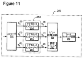
例示的な実施形態に従って、図11は、EPDCCHをチャネル符号化するための、eNB又は通信ノード110といった他の送信ノード内の、チャネル符号化回路250の主要な機能エレメント群を示している。図11に見られるように、eNBといった通信ノード110は、エンコーダ252、インターリーブ回路254、ビット収集回路258、及びレートマッチング回路260を含む。図11に示したコンポーネントは、1つ以上のプロセッサ、ハードウェア、ファームウェア又はそれらの組合せにより実装され得る。エンコーダ252へは、情報ビットを含むEPDCCHペイロード及び付加されるCRCビットが入力され得る。エンコーダ252は、EPDCCHペイロード及び付加されるCRCビットを符号化して、符号化ビットシーケンスを生成する。これは、上のアクション1001及び1002への言及である。エンコーダ252は、例えば、レート1/3畳み込みエンコーダを含んでよい。よって、テールバイティング畳み込みエンコーダの入力においてペイロードサイズがNビットである場合、エンコーダ252の出力において3×Nビットが存在する。代替的に、ブロック符号及びターボ符号といった他の前方誤り訂正(FEC)符号もまた使用されてよい。
In accordance with an exemplary embodiment, FIG. 11 shows the main functional elements of
図11に示したように、エンコーダ252から出力される符号化ビットは、インターリーブ回路254へ入力される。インターリーブ回路254の機能は、符号化ビットを並び替えてバーストエラーに対するロバスト性を増加させることである。これは、上のアクション1003への言及である。1つの例示的な実施形態において、インターリーブ回路254は、複数のサブブロックインターリーバ256を含む。エンコーダ252により出力される符号化ビットストリームは、複数のサブストリームへと分割され、それらサブストリームは、それぞれのサブブロックインターリーバ256へと入力される。サブブロックインターリーバ256へと供給されたサブストリームは、それぞれdk (0)、dk (1)及びdk (2)と表記され得る。サブブロックインターリーバ256は、それぞれのビットストリームdk (0)、dk (1)及びdk (2)をインターリーブして、出力シーケンスvk (0)、vk (1)及びvk (2)を生成する。
As shown in FIG. 11, the encoded bits output from the
ビット収集回路258は、出力シーケンスvk (0)、vk (1)及びvk (2)を循環バッファ260へと収集する。これは、上のアクション1004への言及である。出力シーケンスは、循環バッファ260へとシーケンシャルに読み取られ得る。レートマッチング回路262は、循環バッファ260から符号化ビットを読み取って、EPDCCHへ割当てられた制御チャネルエレメントを満たしていく。これは、上のアクション1005への言及である。送信されるビット数が循環バッファ260のサイズを上回る場合には、レートマッチング回路262は、循環バッファ260の冒頭へ周回し(wraps)、ビットの読み取りを続ける。これは、循環バッファを必要とされる回数だけ周回して読み取ることにより、符号化されるメッセージが任意の数の物理チャネルビットへレートマッチングされ得ることから、循環バッファの構造の特徴である。
循環バッファ260内の符号化ビット数がEPDCCHへ割当てられたeCCEのサブセット内のビット数に等しい場合、即ち、EPDCCHメッセージの符号化において使用される実際のeCCEよりも少ない場合には、問題が生じ得る。そうしたケースでは、符号化ビットシーケンスは、2回以上繰り返され、各反復は、循環バッファ260内の同じ位置で始まる。このケースでは、CRCは、2つ以上の異なるアグリゲーションレベルについて通過(pass)し、曖昧性をもたらし得る。例えば、アグリゲーションレベル4の送信メッセージが有し得るその符号化ビットの前半部は、アグリゲーションレベル2の対応する符号化メッセージに完全に適合する。よって、UE120は、想定されるアグリゲーションレベル2でEPDCCHメッセージを正確に符号化するかもしれず、CECチェックはメッセージが正常であることを示すであろう。よって、メッセージは正確に受信されるが、復号時に使用されるアグリゲーションレベルは送信時とは同じでない。
A problem arises when the number of coded bits in circular buffer 260 is equal to the number of bits in the subset of eCCEs assigned to EPDCCH, ie less than the actual eCCE used in the coding of EPDCCH messages. obtain. In such a case, the encoded bit sequence is repeated more than once, and each iteration begins at the same location in the circular buffer 260. In this case, the CRC may pass for two or more different aggregation levels, resulting in ambiguity. For example, the first half of the encoded bits that an
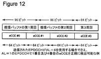
また別のより詳細な例において、16ビットの情報フィールドがあるとして、それは16ビットのCRC追加後には32ビットのペイロードサイズとなり、アグリゲーションレベル4で送信され、eCCEごとに利用可能なREの数は64ビットであるものとする。合計ではよって256個の符号化ビットが存在し、及びレートマッチングバッファは96ビットを保持し、これは図12に見られるように2と2/3回循環的に読み取られることになる。実際に送信される符号語が4つのeCCEへとマッピングされるとしても、DCIメッセージを最初のeCCE又は最後のeCCEのみを用いて復号することが可能である。図12に示した例では、第1及び第4のeCCEは、送信されたEPDCCHがAL=4を使用する場合であっても、アグリゲーションレベル(AL)=1のEPDCCHとして正確に検出されるはずである。
In another more detailed example, if there is a 16-bit information field, it will have a 32-bit payload size after the addition of a 16-bit CRC, transmitted at
従って、eCCEごとに64個の利用可能なビットがあれば、32ビットのペイロードはAL=1とAL=4との間の曖昧性を生じさせ、最初のeCCEのインデックスに関する曖昧性をも生じさせる。さらなる分析を行うと、この例について、ペイロード{16,32,64,128}は同様の曖昧性を生じさせることが示される。但し、代わりにeCCEごとに62ビットが存在する場合、問題となるペイロードは代わりに{31,62,124}である。よって、このペイロードのセットはeCCEごとに利用可能なREの数に大きく依存し、その数は可変的であり、問題のあるペイロードのセットをリスト化して1つ以上のゼロビットを付加するPDCCHの方法はEPDCCHについては現実的な解決策ではないことが明白である。 Thus, if there are 64 available bits per eCCE, the 32-bit payload creates an ambiguity between AL = 1 and AL = 4 and also creates an ambiguity regarding the index of the first eCCE. . Further analysis shows that for this example, the payload {16, 32, 64, 128} produces a similar ambiguity. However, if there are 62 bits per eCCE instead, the payload in question is instead {31, 62, 124}. Thus, this set of payloads is highly dependent on the number of REs available per eCCE, the number is variable, and the PDCCH method of listing problematic payload sets and adding one or more zero bits It is clear that EPDCCH is not a realistic solution.
曖昧性が生じるのは、符号化ビットの1番目のパートが1番目のeCCEへ、2番目のパートが2番目のeCCEへなどといったようにマッピングされるという意味で、eCCEがEPDCCH内で連続的な順序でREへとマッピングされる場合である。これを克服するために、ここでのいくつかの実施形態では、符号化されるEPDCCHビットのマッピングは、代わりに、マッピングがeCCEにより予約されるリソースにわたって構造化された手法で分散されるように実行される。これら実施形態によれば、EPDCCHは、アグリゲーションレベルに依存するようにREへマッピングされる。これは、上のアクション1007への言及である。 Ambiguity occurs in the sense that the first part of the coded bits is mapped to the first eCCE, the second part to the second eCCE, etc. This is a case where mapping to RE is performed in a random order. To overcome this, in some embodiments here, the mapping of the encoded EPDCCH bits is instead distributed in a structured manner across the resources reserved by eCCE. Executed. According to these embodiments, the EPDCCH is mapped to the RE so as to depend on the aggregation level. This is a reference to action 1007 above.
次に、複数のリソースにわたる構造化された手法を実行するための例示的な方法が説明される。各アグリゲーションレベルについて、EPDCCHメッセージはeCCEのセットにより構成され、各eCCEは、複数のeREGのセットへとマッピングされる。各eREGは、PRBペア内のREの一意なグループであり、EPDCCHメッセージは、eCCEが対応する複数のeREGを構成するREのセットへとマッピングされる。EPDCCHメッセージに属する割当てられたeREGにより予約されるREのセットを見ると、EPDCCHシンボルがそこにマッピングされる順序は、様々な手法で選択され得る。これら例示的な実施形態での順序は、アグリゲーションレベルに依存し、但し他のオプションもまた可能である。 Next, an exemplary method for performing a structured approach across multiple resources is described. For each aggregation level, the EPDCCH message is composed of a set of eCCEs, and each eCCE is mapped to a plurality of sets of eREGs. Each eREG is a unique group of REs within the PRB pair, and the EPDCCH message is mapped to a set of REs that constitute a plurality of eREGs to which the eCCE corresponds. Looking at the set of REs reserved by the assigned eREG belonging to the EPDCCH message, the order in which the EPDCCH symbols are mapped there can be selected in various ways. The order in these exemplary embodiments depends on the aggregation level, although other options are also possible.
例えば、各PRBペアの範囲内で、全ての割当てられたeCCEに属する割当てられたeREGにわたって、好適には全ての割当てられたeREGにわたってサブキャリア優先方式でEPDCCHシンボルをマッピングすることにより、図13に示したようなeREGのインターリーブが獲得され、eCCEのインターリーブもまた獲得され得る。eREGの数はアグリゲーションレベル依存であることから、マッピング順序もまたアグリゲーションレベル依存になる。UE120は、間違ったアグリゲーションレベルを想定した場合、EPDCCHメッセージの復号に失敗することになり、それによって曖昧性が解決される。図13は、例示的な実施形態に従っていかにeCCEがeREGへとマッピングされ得るかを示している。
For example, within the range of each PRB pair, by mapping the EPDCCH symbols over all assigned eREGs belonging to all assigned eCCEs, preferably over all assigned eREGs in a subcarrier priority manner, FIG. EREG interleaving as shown may be obtained, and eCCE interleaving may also be obtained. Since the number of eREGs depends on the aggregation level, the mapping order also depends on the aggregation level. If the
図13に示した例において、1つのeCCEが太線で囲まれたボックスにより示したeREG0、4、8及び12へとマッピングされており、別のeCCEが破線で囲まれたボックスにより示したeREG1、5、9及び13へとマッピングされている。EPDCCHがPRBペアの範囲内で全てのeREGにわたって周波数優先的にマッピングされる場合、第1のeCCEのみを使用するメッセージは、1番目のOFDMシンボル内の0、4及び8で示したREへ、続いて2番目のOFDMシンボル内のRE12、0、4などへとマッピングされるはずである。アグリゲーションレベル2を使用するEPDCCHメッセージについて、EPDCCHは、サブキャリア優先方式で、1番目のOFDMシンボル内の0、1、4、5、8及び9としてマークされたREへ、同様に2番目のOFDMシンボル内のREへマッピングされるはずである。間違ったアグリゲーションレベルの前提の下でEPDCCHの復号を試行するUEは、異なるeCCEに属するREのこのインターリーブに起因して、EPDCCHを成功裏に復号することができないであろう。
In the example shown in FIG. 13, one eCCE is mapped to eREG0, 4, 8, and 12 indicated by a box surrounded by a thick line, and another eCCE is indicated by a box surrounded by a broken line. 5, 9 and 13 are mapped. If the EPDCCH is frequency-first mapped across all eREGs within the PRB pair, a message using only the first eCCE will be sent to the RE indicated by 0, 4 and 8 in the first OFDM symbol, It should then be mapped to
よって、1よりも大きいアグリゲーションレベルについて、この例は、eCCEがインターリーブされることを示しており、それは実質的にアグリゲーションレベル依存のREマッピングに帰結する。 Thus, for aggregation levels greater than 1, this example shows that eCCE is interleaved, which results in a substantially aggregation level dependent RE mapping.
他の例において、EPDCCHのマッピングは、EPDCCHに属するPRBペア内の全てのeREGにわたってサブキャリア優先方式で行われ、次に時間にわたって行われるこれもまた、マッピングに起因するeCCEのインターリーブを達成し、マッピングは使用されるアグリゲーションレベルに依存するようになる。UE120が間違ったアグリゲーションレベルを想定する場合、UE120はEPDCCHメッセージの復号に失敗することになり、よって曖昧性が解決される。
In another example, the EPDCCH mapping is performed in a subcarrier-first manner across all eREGs in the PRB pair belonging to the EPDCCH, and then over time, which also achieves eCCE interleaving due to the mapping, The mapping will depend on the aggregation level used. If
いくつかの例示的な実施形態によれば、EPDCCHの復号時に正確なアグリゲーションレベルが使用されたかを検出する目的で、各DCIメッセージは、アグリゲーションレベル固有のスクランブリングシーケンスでスクランブリングされてもよい。これは、上のアクション1008への言及である。 According to some exemplary embodiments, each DCI message may be scrambled with an aggregation level specific scrambling sequence in order to detect if the correct aggregation level was used when decoding the EPDCCH. This is a reference to action 1008 above.
さらなる例において、シフト関数は、以下のテーブル4により与えられる。さらに、同じ数値を共有するアグリゲーションレベルが存在しない限りで任意の数値に各アグリゲーションレベルが関連付けられる他の例を予見することが可能である。 In a further example, the shift function is given by Table 4 below. Furthermore, it is possible to foresee another example in which each aggregation level is associated with an arbitrary numerical value as long as there is no aggregation level sharing the same numerical value.
例示的な実施形態によれば、3つの変数Y、X及びZのうちの1つ又は複数が初期化関数から省略され又はゼロへ設定されてもよい。現行の実施形態において、通信ノード110は、UE120への送信前にEPDCCHメッセージのスクランブリングを実行する。UE120は、受信機の処理において、EPDCCHメッセージを復号する自身の処理の一部として、逆スクランブリングを実行するであろう。
According to an exemplary embodiment, one or more of the three variables Y, X and Z may be omitted from the initialization function or set to zero. In the current embodiment, the
アグリゲーションレベルに基づく巡回シフト関数の一例は、テーブル4において与えられている。上の例では巡回シフトは変調シンボルを対象として実行されるが、巡回シフトはプリコーディングされた変調シンボルを対象として実行されてもよい。 An example of a cyclic shift function based on the aggregation level is given in Table 4. In the above example, the cyclic shift is performed on the modulation symbol, but the cyclic shift may be performed on the precoded modulation symbol.
例示的な実施形態は、EPDCCHメッセージの間違ったアグリゲーションレベルの検出に起因する曖昧性の除去を可能とし、A/Nリソースは最初のeCCEのインデックスにより与えられることから、これは、間違ったUL ACK/NACK(A/N)リソースの選択の問題の除去につながる。アグリゲーションレベル及びそれに応じてeCCEの開始インデックスが正確に検出される場合、A/Nリソース選択の問題はもはや存在しない。 The exemplary embodiment allows for disambiguation due to detection of the wrong aggregation level of the EPDCCH message, and this is because the A / N resource is given by the index of the first eCCE. / NACK (A / N) leads to elimination of resource selection problem. The problem of A / N resource selection no longer exists if the aggregation level and correspondingly the starting index of eCCE is detected correctly.
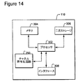
図10に関連して上述したEPDCCHメッセージのシンボルをマッピングするための方法アクションを実行するために、通信ノード110は、図11及び図14に描いた以下の構成を含む。上で言及した通り。
To perform the method actions for mapping the symbols of the EPDCCH message described above in connection with FIG. 10, the
通信ノード110は、プロセッサ302又は複数のプロセッサコアと、メモリ304と、1つ以上の二次ストレージデバイス306と、通信ノード110と例えばUE120又は他のUEといった他のノード/デバイスとの間の通信を遂行するための通信用インタフェース308といったインタフェースユニットと、チャネル符号化回路250と、を含み得る。チャネル符号化回路250は、図11に描かれており、上で説明済みである。図14に描いたように、それは通信ノード110内に含められる。代替的に、通信ノード110は、上で説明した例示的な実施形態において説明したメッセージを受信し及び復号することの可能なUEとなるように構成されてもよい。インタフェースユニット308は、例えば、適切な標準に従ってエアインタフェース上で無線信号を送受信するように構成される送受信機を含み得る。上述したように、EPDCCHは、1つ以上のアグリゲーションレベルを含む。各アグリゲーションレベルについて、EPDCCHメッセージは、eCCEのセットにより構成される。各eCCEは、複数のeREGのセットへとマッピングされ、各eREGは、PRBペア内のREのグループである。通信ノード110は、例えば、eNodeB又はリレーノードであってもよい。
通信ノード110は、EPDCCHメッセージのシンボルを、eCCEのセットに対応する複数のeREGを構成するREのセットへとマッピングするチャネル符号化回路250を含む。上記EPDCCHシンボルが上記REのセットへとマッピングされる順序は、アグリゲーションレベルに依存する。
The
チャネル符号化回路250は、EPDCCHシンボルを、複数のPRBペアのEPDCCHセットの割当てられるeREGにわたって、サブキャリア優先方式でマッピングし、次に時間にわたってマッピングする、ようにさらに構成され得る。
いくつかの実施形態において、チャネル符号化回路250は、EPDCCHシンボルを、各PRBペアの範囲内の割当てられるeREGにわたって、サブキャリア優先方式でマッピングし、次に時間にわたってマッピングし、次にEPDCCHセット内の複数のPRBペアにわたってマッピングすることにより、EPDCCHメッセージのシンボルをREのセットへとマッピングする、ようにさらに構成される。
In some embodiments,
いくつかの実施形態において、チャネル符号化回路250は、EPDCCHシンボルを、EPDCCHセットに属する全てのPRBペア内の割当てられるeREGにわたって、サブキャリア優先方式でマッピングし、次に時間にわたってマッピングすることにより、EPDCCHメッセージのシンボルをREのセットへとマッピングする、ようにさらに構成される。
In some embodiments, the
チャネル符号化回路250は、EPDCCHメッセージのアグリゲーションレベル固有のスクランブリングを実行するようにさらに構成されてもよい。
いくつかの実施形態において、チャネル符号化回路250は、1つ以上のビットを含む等サイズ又は別サイズのビットチャンクへと符号化ビットをグループ化し、アグリゲーションレベルに依存する順序で、ビットチャンクを並び替えることにより、EPDCCHメッセージのアグリゲーションレベル固有のスクランブリングを実行する、ようにさらに構成される。
In some embodiments, the
いくつかの実施形態において、チャネル符号化回路250は、1つ以上のシンボルを含む等サイズ又は別サイズのシンボルチャンクへと変調EPDCCHシンボルをグループ化し、アグリゲーションレベルに依存する順序で、チャンクを並び替えることにより、EPDCCHメッセージのアグリゲーションレベル固有のスクランブリングを実行する、ようにさらに構成される。
In some embodiments, the
チャネル符号化回路250は、EPDCCHの各DCIメッセージを、その対応するアグリゲーションレベル固有のスクランブリングシーケンスでスクランブリングすることにより、EPDCCHメッセージのアグリゲーションレベル固有のスクランブリングを実行する、ようにさらに構成されてもよい。
The
EPDCCHメッセージのアグリゲーションレベル固有のスクランブリングを実行するためのスクランブリングシーケンスの初期化は、アグリゲーションレベルに依存し得る。 Initialization of the scrambling sequence to perform aggregation level specific scrambling of the EPDCCH message may depend on the aggregation level.
チャネル符号化回路250は、符号化ビットを巡回シフトすることにより、EPDCCHメッセージのアグリゲーションレベル固有のスクランブリングを実行する、ようにさらに構成されてもよく、符号化ビットの当該巡回シフトは、アグリゲーションレベル依存の巡回シフトである。
The
当該巡回シフトは、変調シンボル又はプリコーディングされた変調シンボルについて実行されてよい。 The cyclic shift may be performed on modulation symbols or precoded modulation symbols.
通信ノード110は、EPDCCHペイロードビットを符号化ビットへと符号化し、及びCRCビットを付加するように構成されるエンコーダ252、をさらに含んでもよい。エンコーダ252は、図11に示されている。
The
通信ノード110は、複数の出力シーケンスの各々をインターリーブするように構成されるインターリーブ回路254、をさらに含んでもよい。インターリーブ回路254は、図11に示されている。
通信ノード110は、EPDCCHへ割当てられる物理チャネルビットの数に適合するように、複数の出力シーケンスを読み取るように構成されるレートマッチング回路262であって、当該レートマッチング回路のビットの出力シーケンスをスクランブリングするように構成されるレートマッチング回路262、をさらに含んでもよい。レートマッチング回路262もまた、図11に示されている。
The
インタフェース308は、マッピングされたEPDCCHメッセージをUE120へ送信するように構成されてよく、EPDCCHメッセージの当該マッピングは、EPDCCHペイロードのUE120による受信時の使用されるアグリゲーションレベルを、UE120が検出することを可能とする。
The interface 308 may be configured to send a mapped EPDCCH message to the
通信ノード110は、出力シーケンスをバッファへと収集するように構成されるビット収集回路258、をさらに含んでもよく、当該バッファは、通信ノード110の循環バッファであってよい。ビット収集回路258は、図11に示されている。
The
開示された例示的な実施形態は、EPDCCHメッセージの間違ったアグリゲーションレベルの検出に起因する曖昧性の除去を提供する。理解されるべきこととして、本説明は、本発明を限定することを意図されていない。反対に、例示的な実施形態は、変形例、修正例及び均等物をカバーするように意図されており、それらは請求項の範囲内に含まれる。さらに、例示的な実施形態の詳細な説明において、ここでの実施形態の包括的な理解を提供する目的で多数の特定の詳細が説明されている。しかしながら、当業者は、多様な実施形態がそうした特定の詳細無しで実践され得ることを理解するはずである。 The disclosed exemplary embodiments provide disambiguation due to detection of incorrect aggregation levels in EPDCCH messages. It should be understood that this description is not intended to limit the invention. On the contrary, the exemplary embodiments are intended to cover variations, modifications, and equivalents, which are included within the scope of the claims. Furthermore, in the detailed description of the exemplary embodiments, numerous specific details are set forth in order to provide a comprehensive understanding of the embodiments herein. However, one of ordinary skill in the art should understand that various embodiments may be practiced without such specific details.
本例示的な実施形態の特徴及びエレメントが特定の組合せで実施形態において説明されているが、各特徴又はエレメントは、実施形態の他の特徴及びエレメントの無いまま単独で使用されてもよく、又は、ここで開示された他の特徴及びエレメントを伴うとしても伴わないとしても多様な組合せで使用されてよい。本出願において提供されている方法又はフローチャートは、固有にプログラムされたコンピュータ又はプロセッサによる実行用のコンピュータ読取可能なストレージにおいて有形的に具現化されたコンピュータプログラム、ソフトウェア又はファームウェアで実装されてもよい。 Although the features and elements of the exemplary embodiment are described in the embodiments in a particular combination, each feature or element may be used alone without the other features and elements of the embodiment, or It may be used in various combinations, with or without other features and elements disclosed herein. The methods or flowcharts provided in this application may be implemented in a computer program, software or firmware tangibly embodied in a computer readable storage for execution by a uniquely programmed computer or processor.
例示的な実施形態によれば、LTE(Long Term Evolution)システムにおいて拡張物理ダウンリンク制御チャネル(EPDCCH)の検出エラーを除去するための方法があり、当該方法は:情報ビットを含むEPDCCHペイロード及び付加される巡回冗長検査(CRC)ビットを符号化ビットへと符号化することと;上記符号化ビットを複数の出力シーケンスへと並び替えることと;上記出力シーケンスをバッファへと収集することと;レートマッチング回路により、上記出力シーケンスを、上記EPDCCHにより割当てられる制御チャネルエレメントを満たしていくように読み取ることと;上記EPDCCHのアグリゲーションレベル固有のスクランブリングを実行することと、を含む。 According to an exemplary embodiment, there is a method for eliminating detection errors of an enhanced physical downlink control channel (EPDCCH) in a Long Term Evolution (LTE) system, the method comprising: an EPDCCH payload including information bits and an additional Encoding the cyclic redundancy check (CRC) bits to be encoded bits; reordering the encoded bits into a plurality of output sequences; collecting the output sequences into a buffer; Reading the output sequence with a matching circuit to fill the control channel elements assigned by the EPDCCH; and performing scrambling specific to the aggregation level of the EPDCCH.
例示的な実施形態によれば、上記EPDCCHのアグリゲーションレベル固有のスクランブリングを実行する上記ステップは、アグリゲーションレベル固有のスクランブリングシーケンスで各DCIメッセージをスクランブリングすること、をさらに含む。例示的な実施形態によれば、上記スクランブリングシーケンスの初期化が上記アグリゲーションレベルに依存する。他の例示的な実施形態によれば、上記バッファは、循環バッファであってよい。 According to an exemplary embodiment, the step of performing aggregation level specific scrambling of the EPDCCH further comprises scrambling each DCI message with an aggregation level specific scrambling sequence. According to an exemplary embodiment, initialization of the scrambling sequence depends on the aggregation level. According to another exemplary embodiment, the buffer may be a circular buffer.
例示的な実施形態によれば、上記EPDCCHのアグリゲーションレベル固有のスクランブリングを実行する上記ステップは、上記符号化ビットを巡回シフトすること、をさらに含む。例示的な実施形態によれば、上記符号化ビットの上記巡回シフトは、アグリゲーションレベル依存の巡回シフトであってよい。 According to an exemplary embodiment, the step of performing aggregation level specific scrambling of the EPDCCH further includes cyclically shifting the coded bits. According to an exemplary embodiment, the cyclic shift of the coded bits may be an aggregation level dependent cyclic shift.
例示的な実施形態によれば、上記EPDCCHのアグリゲーションレベル固有のスクランブリングを実行する上記ステップは、アグリゲーションレベルに依存する、EPDCCHからリソースエレメント(RE)へのマッピングを有すること、をさらに含む。 According to an exemplary embodiment, the step of performing aggregation level specific scrambling of the EPDCCH further comprises having an EPDCCH to resource element (RE) mapping dependent on the aggregation level.
例示的な実施形態によれば、上述した方法のいずれか、全て又はいくつかのサブセットは、上記LTEシステムに関連付けられるeNodeB又は例えばリレーノードといった他の送信ノードにより実装され得る。eNodeBは、プロセッサ、メモリ、通信用インタフェース、及びチャネル符号化回路を含んでよく、そのうちの1つ以上は、ここまでの段落において説明したステップ群を実行するように構成される。例示的な実施形態によれば、上記チャネル符号化回路は、エンコーダ、インターリーブ回路、ビット収集回路及びレートマッチング回路を含み得る。 According to an exemplary embodiment, any, all or some subset of the methods described above may be implemented by an eNodeB associated with the LTE system or other transmitting node such as a relay node. The eNodeB may include a processor, a memory, a communication interface, and a channel encoding circuit, one or more of which are configured to perform the steps described in the preceding paragraphs. According to an exemplary embodiment, the channel coding circuit may include an encoder, an interleave circuit, a bit collection circuit, and a rate matching circuit.
例示的な実施形態によれば、EPDCCHメッセージをハンドリングするための通信ノード110における方法が提供される。当該方法は:
情報ビットを含むEPDCCHペイロード及び付加される巡回冗長検査(CRC)ビットを、符号化ビットへと符号化することと;
上記符号化ビットを複数の出力シーケンスへと並び替えることと;
上記出力シーケンスをバッファへと収集することと;
レートマッチング回路により、上記出力シーケンスを、上記EPDCCHにより割当てられる制御チャネルエレメントを満たしていくように読み取ることと;
上記EPDCCHのアグリゲーションレベル固有のスクランブリングを実行することと、
を含む。
According to an exemplary embodiment, a method in
Encoding the EPDCCH payload including information bits and the appended cyclic redundancy check (CRC) bits into encoded bits;
Reordering the coded bits into a plurality of output sequences;
Collecting the output sequence into a buffer;
Reading the output sequence with a rate matching circuit to fill the control channel elements allocated by the EPDCCH;
Performing said EPDCCH aggregation level specific scrambling;
including.
そして、アグリゲーションレベル固有のスクランブリング後の上記EPDCCHメッセージは、UE120へと送信され得る。
Then, the EPDCCH message after scrambling specific to the aggregation level may be transmitted to the
上記EPDCCHの上記アグリゲーションレベル固有のスクランブリングは、上記EPDCCHメッセージの、UE120による受信時の使用される上記アグリゲーションレベルを、UE120が検出することを可能とする。
The scrambling specific to the aggregation level of the EPDCCH allows the
Claims (30)
前記EPDCCHメッセージの前記シンボルを、前記eCCEのセットに対応する前記複数のeREGを構成する前記REのセットへとマッピングすること(1007)と、
前記EPDCCHシンボルが前記REのセットへとマッピングされる順序は、前記アグリゲーションレベルに依存することと、
を特徴とする、方法。 A method at a communication node (110) for mapping symbols of an enhanced physical downlink control channel (EPDCCH) message, wherein the EPDCCH includes one or more aggregation levels, and for each aggregation level, the EPDCCH message is , Each channel is mapped to a set of multiple extended resource element groups (eREGs), and each eREG is a resource element (RE) in a physical resource block (PRB) pair. ) And the method is
Mapping (1007) the symbols of the EPDCCH message to the set of REs constituting the plurality of eREGs corresponding to the set of eCCEs;
The order in which the EPDCCH symbols are mapped to the set of REs depends on the aggregation level;
A method characterized by.
前記複数の出力シーケンスの各々をインターリーブすること(1003)と、
前記EPDCCHへ割当てられる物理チャネルビットの数に適合するように、前記複数の出力シーケンスを読み取ること(1005)と、
ビットの前記出力シーケンスをスクランブリングすること(1006)と、
をさらに含む、請求項1〜4のいずれかに記載の方法。 Adding cyclic redundancy check (CRC) bits (1001), encoding EPDCCH payload bits and CRC bits into three output parity streams of encoded bits (1002);
Interleaving each of the plurality of output sequences (1003);
Reading the plurality of output sequences to match the number of physical channel bits allocated to the EPDCCH (1005);
Scrambling the output sequence of bits (1006);
The method according to claim 1, further comprising:
をさらに含む、請求項1〜5のいずれかに記載の方法。 Performing aggregation level specific scrambling of the EPDCCH message (1008);
The method according to claim 1, further comprising:
をさらに含む、請求項1〜6のいずれかに記載の方法。 Sending the mapped EPDCCH message to a user equipment (UE) (120) (1009), and the mapping of the EPDCCH message is used in the aggregation when the UE (120) receives the EPDCCH payload. Enabling the UE (120) to detect a level;
The method according to claim 1, further comprising:
1つ以上のビットを含む等サイズ又は別サイズのビットチャンクへと前記符号化ビットをグループ化することと、
前記アグリゲーションレベルに依存する順序で、前記ビットチャンクを並び替えることと、
をさらに含む、請求項6〜7のいずれかに記載の方法。 Performing aggregation level specific scrambling of the EPDCCH message (1008)
Grouping the coded bits into equal-sized or different-sized bit chunks containing one or more bits;
Reordering the bit chunks in an order that depends on the aggregation level;
The method according to claim 6, further comprising:
1つ以上のシンボルを含む等サイズ又は別サイズのシンボルチャンクへと変調EPDCCHシンボルをグループ化することと、
前記アグリゲーションレベルに依存する順序で、前記チャンクを並び替えることと、
をさらに含む、請求項6〜7のいずれかに記載の方法。 Performing aggregation level specific scrambling of the EPDCCH message (1008)
Grouping the modulated EPDCCH symbols into equal-sized or different-sized symbol chunks containing one or more symbols;
Reordering the chunks in an order that depends on the aggregation level;
The method according to claim 6, further comprising:
をさらに含む、請求項1〜13のいずれかに記載の方法。 Collecting the output sequence into a buffer that is a circular buffer (1004);
The method according to claim 1, further comprising:
前記EPDCCHメッセージの前記シンボルを、前記eCCEのセットに対応する前記複数のeREGを構成する前記REのセットへとマッピングするように構成されるチャネル符号化回路(250)、
を含むことと、
前記EPDCCHシンボルが前記REのセットへとマッピングされる順序は、前記アグリゲーションレベルに依存することと、
を特徴とする、通信ノード(110)。 A communication node (110) for mapping symbols of an enhanced physical downlink control channel (EPDCCH) message, wherein the EPDCCH includes one or more aggregation levels, and for each aggregation level, the EPDCCH message is a control channel Each eCCE is mapped to a set of multiple extended resource element groups (eREGs), and each eREG is a group of resource elements (RE) in a physical resource block (PRB) pair. And the communication node is
A channel encoding circuit (250) configured to map the symbols of the EPDCCH message to the set of REs constituting the plurality of eREGs corresponding to the set of eCCEs;
Including
The order in which the EPDCCH symbols are mapped to the set of REs depends on the aggregation level;
A communication node (110) characterized by:
前記複数の出力シーケンスの各々をインターリーブするように構成されるインターリーブ回路(254)と、
前記EPDCCHへ割当てられる物理チャネルビットの数に適合するように、前記複数の出力シーケンスを読み取るように構成されるレートマッチング回路であって、当該レートマッチング回路のビットの前記出力シーケンスをスクランブリングするように構成される当該レートマッチング回路(262)と、
をさらに含む、請求項16〜19のいずれかに記載の通信ノード(110)。 An encoder (252) configured to add cyclic redundancy check (CRC) bits and encode the EPDCCH payload bits and CRC bits into three output parity streams of encoded bits;
An interleaving circuit (254) configured to interleave each of the plurality of output sequences;
A rate matching circuit configured to read the plurality of output sequences to match the number of physical channel bits allocated to the EPDCCH, wherein the output sequence of bits of the rate matching circuit is scrambled. The rate matching circuit (262) configured as follows:
The communication node (110) according to any of claims 16 to 19, further comprising:
前記EPDCCHメッセージの当該マッピングは、前記EPDCCHペイロードの前記UE(120)による受信時の使用される前記アグリゲーションレベルを、前記UE(120)が検出することを可能とする、
請求項16〜21のいずれかに記載の通信ノード(110)。 A communication interface (308) configured to transmit the mapped EPDCCH message to a user equipment (UE) (120);
The mapping of the EPDCCH message allows the UE (120) to detect the aggregation level that is used when the UE (120) receives the EPDCCH payload.
A communication node (110) according to any of claims 16-21.
前記バッファは、前記通信ノード(110)の循環バッファである、
請求項16〜28のいずれかに記載の通信ノード(110)。 A bit collection circuit (258) configured to collect the output sequence into a buffer;
The buffer is a circular buffer of the communication node (110).
Communication node (110) according to any of claims 16 to 28.
Applications Claiming Priority (3)
| Application Number | Priority Date | Filing Date | Title |
|---|---|---|---|
| US201261702817P | 2012-09-19 | 2012-09-19 | |
| US61/702,817 | 2012-09-19 | ||
| PCT/SE2013/050078 WO2014046591A1 (en) | 2012-09-19 | 2013-01-30 | Method and communication node for mapping an enhanced physical downlink control channel, epdcch, message |
Publications (2)
| Publication Number | Publication Date |
|---|---|
| JP2015536070A true JP2015536070A (en) | 2015-12-17 |
| JP5956688B2 JP5956688B2 (en) | 2016-07-27 |
Family
ID=47741239
Family Applications (1)
| Application Number | Title | Priority Date | Filing Date |
|---|---|---|---|
| JP2015533012A Active JP5956688B2 (en) | 2012-09-19 | 2013-01-30 | Method and communication node for mapping enhanced physical downlink control channel (EPDCCH) messages |
Country Status (10)
| Country | Link |
|---|---|
| EP (1) | EP2898621B1 (en) |
| JP (1) | JP5956688B2 (en) |
| CN (1) | CN104756434B (en) |
| AR (1) | AR094444A1 (en) |
| AU (1) | AU2013318674B2 (en) |
| ES (1) | ES2567292T3 (en) |
| IN (1) | IN2014DN06712A (en) |
| MX (1) | MX343395B (en) |
| PL (1) | PL2898621T3 (en) |
| WO (1) | WO2014046591A1 (en) |
Families Citing this family (12)
| Publication number | Priority date | Publication date | Assignee | Title |
|---|---|---|---|---|
| US11290929B2 (en) | 2015-05-22 | 2022-03-29 | Telefonaktiebolaget L M Ericsson (Publ) | Method and system relating to handover |
| US10575150B2 (en) | 2015-09-14 | 2020-02-25 | Lg Electronics Inc. | Method and apparatus for transceiving messages from V2X terminal in wireless communication system |
| WO2017052661A1 (en) | 2015-09-26 | 2017-03-30 | Intel Corporation | Multichip package link error detection |
| CN106656894A (en) * | 2015-10-30 | 2017-05-10 | 中兴通讯股份有限公司 | Method and apparatus for sending an enhanced physical downlink control channel (EPDCCH) |
| US10791548B2 (en) | 2016-05-02 | 2020-09-29 | Qualcomm Incorporated | Search space design for control channel in wireless communication |
| EP3577808A1 (en) * | 2017-02-03 | 2019-12-11 | IDAC Holdings, Inc. | Advanced polar codes for control channel |
| US10992433B2 (en) * | 2017-10-25 | 2021-04-27 | Qualcomm Incorporated | Symbol mapping for a downlink control channel |
| CN110198200A (en) * | 2018-02-24 | 2019-09-03 | 华为技术有限公司 | A kind of wireless communications method and device |
| CN112789815B (en) | 2018-09-28 | 2023-03-28 | 中兴通讯股份有限公司 | System and method for bit-level signal processing |
| WO2021120135A1 (en) * | 2019-12-19 | 2021-06-24 | 华为技术有限公司 | Resource determination method and resource determination apparatus |
| CN112636873B (en) * | 2020-12-18 | 2023-03-24 | 浙江三维利普维网络有限公司 | Data transmission method, data transmission device, storage medium and electronic device |
| CN116156628B (en) * | 2021-06-07 | 2026-01-13 | 上海推络通信科技合伙企业(有限合伙) | Method and apparatus in a node for wireless communication |
Citations (6)
| Publication number | Priority date | Publication date | Assignee | Title |
|---|---|---|---|---|
| JP2006510333A (en) * | 2002-12-16 | 2006-03-23 | インターディジタル テクノロジー コーポレイション | Detection, avoidance and / or correction of problematic puncture patterns in a stream of parity bits used when implementing turbo codes |
| WO2008136469A1 (en) * | 2007-05-01 | 2008-11-13 | Ntt Docomo, Inc. | Base station device and method used in mobile communication system |
| JP2010529766A (en) * | 2007-06-08 | 2010-08-26 | テレフオンアクチーボラゲット エル エム エリクソン(パブル) | Convolutional coding with high computational efficiency by rate matching |
| JP2010537509A (en) * | 2007-08-14 | 2010-12-02 | クゥアルコム・インコーポレイテッド | Reference signal generation in wireless communication systems |
| JP2011023942A (en) * | 2009-07-15 | 2011-02-03 | Ntt Docomo Inc | Radio base station apparatus and modulating/coding scheme selecting method |
| WO2012109542A1 (en) * | 2011-02-11 | 2012-08-16 | Interdigital Patent Holdings, Inc | Systems and methods for an enhanced control channel |
Family Cites Families (1)
| Publication number | Priority date | Publication date | Assignee | Title |
|---|---|---|---|---|
| WO2010150512A1 (en) * | 2009-06-22 | 2010-12-29 | パナソニック株式会社 | Wireless communication base station device, wireless communication terminal device, control channel transmission method, and control channel reception method |
-
2013
- 2013-01-30 AU AU2013318674A patent/AU2013318674B2/en active Active
- 2013-01-30 EP EP13705279.1A patent/EP2898621B1/en active Active
- 2013-01-30 PL PL13705279.1T patent/PL2898621T3/en unknown
- 2013-01-30 ES ES13705279.1T patent/ES2567292T3/en active Active
- 2013-01-30 WO PCT/SE2013/050078 patent/WO2014046591A1/en not_active Ceased
- 2013-01-30 MX MX2015003437A patent/MX343395B/en active IP Right Grant
- 2013-01-30 JP JP2015533012A patent/JP5956688B2/en active Active
- 2013-01-30 IN IN6712DEN2014 patent/IN2014DN06712A/en unknown
- 2013-01-30 CN CN201380056537.3A patent/CN104756434B/en active Active
- 2013-09-18 AR ARP130103356A patent/AR094444A1/en active IP Right Grant
Patent Citations (6)
| Publication number | Priority date | Publication date | Assignee | Title |
|---|---|---|---|---|
| JP2006510333A (en) * | 2002-12-16 | 2006-03-23 | インターディジタル テクノロジー コーポレイション | Detection, avoidance and / or correction of problematic puncture patterns in a stream of parity bits used when implementing turbo codes |
| WO2008136469A1 (en) * | 2007-05-01 | 2008-11-13 | Ntt Docomo, Inc. | Base station device and method used in mobile communication system |
| JP2010529766A (en) * | 2007-06-08 | 2010-08-26 | テレフオンアクチーボラゲット エル エム エリクソン(パブル) | Convolutional coding with high computational efficiency by rate matching |
| JP2010537509A (en) * | 2007-08-14 | 2010-12-02 | クゥアルコム・インコーポレイテッド | Reference signal generation in wireless communication systems |
| JP2011023942A (en) * | 2009-07-15 | 2011-02-03 | Ntt Docomo Inc | Radio base station apparatus and modulating/coding scheme selecting method |
| WO2012109542A1 (en) * | 2011-02-11 | 2012-08-16 | Interdigital Patent Holdings, Inc | Systems and methods for an enhanced control channel |
Non-Patent Citations (1)
| Title |
|---|
| JPN6016017738; LG Electronics: 'Remaining details of ECCE and EREG resource mapping' 3GPP TSG-RAN WG1#70b R1-124320 , 20121012 * |
Also Published As
| Publication number | Publication date |
|---|---|
| EP2898621B1 (en) | 2016-03-30 |
| MX2015003437A (en) | 2015-06-22 |
| ES2567292T3 (en) | 2016-04-21 |
| EP2898621A1 (en) | 2015-07-29 |
| AR094444A1 (en) | 2015-08-05 |
| CN104756434A (en) | 2015-07-01 |
| AU2013318674B2 (en) | 2016-04-07 |
| IN2014DN06712A (en) | 2015-05-22 |
| PL2898621T3 (en) | 2016-09-30 |
| MX343395B (en) | 2016-11-04 |
| CN104756434B (en) | 2018-02-02 |
| AU2013318674A1 (en) | 2015-04-02 |
| JP5956688B2 (en) | 2016-07-27 |
| WO2014046591A1 (en) | 2014-03-27 |
Similar Documents
| Publication | Publication Date | Title |
|---|---|---|
| JP5956688B2 (en) | Method and communication node for mapping enhanced physical downlink control channel (EPDCCH) messages | |
| US9369248B2 (en) | Method and communication node for mapping an enhanced physical downlink control channel, EPDCCH, message | |
| US11716740B2 (en) | Transmissions of downlink control channels for low cost UEs | |
| US11129140B2 (en) | Search process for physical downlink control channels in a communication system | |
| CN110447278B (en) | Systems and methods for supporting asynchronous uplink HARQ and multiple simultaneous transmissions | |
| KR102149758B1 (en) | Method for transmission and reception of harq-ack signal and apparatus therefor | |
| CN105940630B (en) | Method for enhancing HARQ mechanism, user equipment and memory | |
| US9591635B2 (en) | Systems and methods for UE-specific search space and ePDCCH scrambling | |
| KR101932184B1 (en) | Extension of physical downlink control signaling in a communication system | |
| US11528091B2 (en) | Method and apparatus for performing channel coding and decoding in communication or broadcasting system | |
| EP2747306A1 (en) | Method and device for indicating control channel | |
| CN105897373B (en) | A kind of method and system in down control channel transmission transmission block | |
| CN102113261A (en) | Signaling of scheduling permission information in a wireless communication system | |
| KR20190035788A (en) | Method and apparatus for transmitting data | |
| CN102833056A (en) | Method, base station and user equipment for performing channel treatment | |
| CN103379632A (en) | Signal sending method and device |
Legal Events
| Date | Code | Title | Description |
|---|---|---|---|
| A621 | Written request for application examination |
Free format text: JAPANESE INTERMEDIATE CODE: A621 Effective date: 20150416 |
|
| A131 | Notification of reasons for refusal |
Free format text: JAPANESE INTERMEDIATE CODE: A131 Effective date: 20160119 |
|
| A521 | Request for written amendment filed |
Free format text: JAPANESE INTERMEDIATE CODE: A523 Effective date: 20160414 |
|
| TRDD | Decision of grant or rejection written | ||
| A01 | Written decision to grant a patent or to grant a registration (utility model) |
Free format text: JAPANESE INTERMEDIATE CODE: A01 Effective date: 20160517 |
|
| A61 | First payment of annual fees (during grant procedure) |
Free format text: JAPANESE INTERMEDIATE CODE: A61 Effective date: 20160616 |
|
| R150 | Certificate of patent or registration of utility model |
Ref document number: 5956688 Country of ref document: JP Free format text: JAPANESE INTERMEDIATE CODE: R150 |
|
| R250 | Receipt of annual fees |
Free format text: JAPANESE INTERMEDIATE CODE: R250 |
|
| R250 | Receipt of annual fees |
Free format text: JAPANESE INTERMEDIATE CODE: R250 |
|
| R250 | Receipt of annual fees |
Free format text: JAPANESE INTERMEDIATE CODE: R250 |
|
| R250 | Receipt of annual fees |
Free format text: JAPANESE INTERMEDIATE CODE: R250 |
|
| R250 | Receipt of annual fees |
Free format text: JAPANESE INTERMEDIATE CODE: R250 |
|
| R250 | Receipt of annual fees |
Free format text: JAPANESE INTERMEDIATE CODE: R250 |
|
| R250 | Receipt of annual fees |
Free format text: JAPANESE INTERMEDIATE CODE: R250 |