JP2016003729A - 十字軸継手用ヨーク、十字軸継手 - Google Patents
十字軸継手用ヨーク、十字軸継手 Download PDFInfo
- Publication number
- JP2016003729A JP2016003729A JP2014125359A JP2014125359A JP2016003729A JP 2016003729 A JP2016003729 A JP 2016003729A JP 2014125359 A JP2014125359 A JP 2014125359A JP 2014125359 A JP2014125359 A JP 2014125359A JP 2016003729 A JP2016003729 A JP 2016003729A
- Authority
- JP
- Japan
- Prior art keywords
- arms
- pair
- yoke
- joint
- cross shaft
- Prior art date
- Legal status (The legal status is an assumption and is not a legal conclusion. Google has not performed a legal analysis and makes no representation as to the accuracy of the status listed.)
- Granted
Links
Images




Classifications
-
- F—MECHANICAL ENGINEERING; LIGHTING; HEATING; WEAPONS; BLASTING
- F16—ENGINEERING ELEMENTS AND UNITS; GENERAL MEASURES FOR PRODUCING AND MAINTAINING EFFECTIVE FUNCTIONING OF MACHINES OR INSTALLATIONS; THERMAL INSULATION IN GENERAL
- F16D—COUPLINGS FOR TRANSMITTING ROTATION; CLUTCHES; BRAKES
- F16D3/00—Yielding couplings, i.e. with means permitting movement between the connected parts during the drive
- F16D3/16—Universal joints in which flexibility is produced by means of pivots or sliding or rolling connecting parts
- F16D3/26—Hooke's joints or other joints with an equivalent intermediate member to which each coupling part is pivotally or slidably connected
- F16D3/38—Hooke's joints or other joints with an equivalent intermediate member to which each coupling part is pivotally or slidably connected with a single intermediate member with trunnions or bearings arranged on two axes perpendicular to one another
- F16D3/382—Hooke's joints or other joints with an equivalent intermediate member to which each coupling part is pivotally or slidably connected with a single intermediate member with trunnions or bearings arranged on two axes perpendicular to one another constructional details of other than the intermediate member
- F16D3/387—Fork construction; Mounting of fork on shaft; Adapting shaft for mounting of fork
-
- F—MECHANICAL ENGINEERING; LIGHTING; HEATING; WEAPONS; BLASTING
- F16—ENGINEERING ELEMENTS AND UNITS; GENERAL MEASURES FOR PRODUCING AND MAINTAINING EFFECTIVE FUNCTIONING OF MACHINES OR INSTALLATIONS; THERMAL INSULATION IN GENERAL
- F16D—COUPLINGS FOR TRANSMITTING ROTATION; CLUTCHES; BRAKES
- F16D3/00—Yielding couplings, i.e. with means permitting movement between the connected parts during the drive
- F16D3/16—Universal joints in which flexibility is produced by means of pivots or sliding or rolling connecting parts
- F16D3/26—Hooke's joints or other joints with an equivalent intermediate member to which each coupling part is pivotally or slidably connected
- F16D3/38—Hooke's joints or other joints with an equivalent intermediate member to which each coupling part is pivotally or slidably connected with a single intermediate member with trunnions or bearings arranged on two axes perpendicular to one another
- F16D3/382—Hooke's joints or other joints with an equivalent intermediate member to which each coupling part is pivotally or slidably connected with a single intermediate member with trunnions or bearings arranged on two axes perpendicular to one another constructional details of other than the intermediate member
- F16D3/385—Bearing cup; Bearing construction; Bearing seal; Mounting of bearing on the intermediate member
-
- F—MECHANICAL ENGINEERING; LIGHTING; HEATING; WEAPONS; BLASTING
- F16—ENGINEERING ELEMENTS AND UNITS; GENERAL MEASURES FOR PRODUCING AND MAINTAINING EFFECTIVE FUNCTIONING OF MACHINES OR INSTALLATIONS; THERMAL INSULATION IN GENERAL
- F16D—COUPLINGS FOR TRANSMITTING ROTATION; CLUTCHES; BRAKES
- F16D3/00—Yielding couplings, i.e. with means permitting movement between the connected parts during the drive
- F16D3/16—Universal joints in which flexibility is produced by means of pivots or sliding or rolling connecting parts
- F16D3/26—Hooke's joints or other joints with an equivalent intermediate member to which each coupling part is pivotally or slidably connected
- F16D3/38—Hooke's joints or other joints with an equivalent intermediate member to which each coupling part is pivotally or slidably connected with a single intermediate member with trunnions or bearings arranged on two axes perpendicular to one another
- F16D3/40—Hooke's joints or other joints with an equivalent intermediate member to which each coupling part is pivotally or slidably connected with a single intermediate member with trunnions or bearings arranged on two axes perpendicular to one another with intermediate member provided with two pairs of outwardly-directed trunnions on intersecting axes
- F16D3/41—Hooke's joints or other joints with an equivalent intermediate member to which each coupling part is pivotally or slidably connected with a single intermediate member with trunnions or bearings arranged on two axes perpendicular to one another with intermediate member provided with two pairs of outwardly-directed trunnions on intersecting axes with ball or roller bearings
Landscapes
- Engineering & Computer Science (AREA)
- General Engineering & Computer Science (AREA)
- Mechanical Engineering (AREA)
- Power Steering Mechanism (AREA)
Abstract
【解決手段】 軸方向に延びるスリット26を備えた円筒状の基部23と、基部23の一方の端部から軸方向にそれぞれ延び、径方向に互いに対向して、同一方向に貫通した軸受保持孔21がそれぞれ形成された一対のアーム24、25と、を有し、一対のアーム24、25の内径側において、軸受保持孔21の周囲で、一対のアーム24、25の外径側に向かって凹んだ逃げ部30が形成されているものとする。
【選択図】 図3
Description
軸方向に延びるスリットを備えた円筒状の基部と、
前記基部の一方の端部から軸方向にそれぞれ延び、径方向に互いに対向して、同一方向に貫通した軸受保持孔がそれぞれ形成された一対のアームと、を有し、
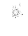
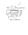
前記一対のアームの内径側において、前記軸受保持孔の周囲で、前記軸受保持孔の中心よりも前記一対のアームの基端部寄りの部分から前記一対のアームの先端にかけて、前記一対のアームの外径側に向かって前記一対のアームの基端部側よりも凹んだ逃げ部が形成されていることを特徴とする十字軸継手用ヨークを提供する。
図1に示すように、実施形態の十字軸継手1は、互いに同じ形状をした対向する2つのヨーク2と、両ヨーク2を相対角度の変化自在に連結するスパイダー4と、各ヨーク2の軸受保持孔21に圧入されてスパイダー4のトルク伝達軸42を回転自在に支持するニードルベアリング5とを主要構成要素としている。
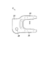
ヨーク2は、鋼から成り、図2、図3に示すように、雌セレーション22aを有するシャフト挿入孔22が穿設された円筒状の基部23と、基部23の一方の端部から相手側のヨーク2に向けて延び、基部23の径方向に対向した一対のアーム24、25とを有している。両アーム24、25には上述した軸受保持孔21が同軸に形成されている。雌セレーション22aは、ブローチ加工などによって形成することができる。
図1に示すように、ニードルベアリング5は、鋼板プレス成形品のシェル51にニードルローラ55を収容した構成をしている。ニードルベアリング5は、スパイダー4のトルク伝達軸42に被さり、軸受保持孔21に圧入されている。
例えば、実施形態に係る十字軸継手1がステアリング装置に用いられる場合、運転者がステアリング操作を行うと、ステアリングシャフト、即ち、入力軸101が所定の操舵トルクをもって回転し、その操舵トルクが十字軸継手1を介してインターミディエイトシャフト、即ち、出力軸102に伝達される。十字継手1において、上記操舵トルクは一方のヨーク2のアーム24、25からスパイダー4のトルク伝達軸42を介して他方のヨーク2のアーム24、25に伝達される。
以下、図7ないし図10を参照して、上記実施形態の2つの一部変形例を説明する。両変形例ともその全体構成は実施形態と略同一であるが、アーム24、25の内径側に形成される逃げ部の形状が異なっている。
2 ヨーク
4 スパイダー
5 ニードルベアリング
21 軸受保持孔
21a 内径側開口端
21b 外径側開口端
22 シャフト挿入孔
22a 雌セレーション
23 基部
24、25 アーム
26 スリット
27 ねじ孔
28 ボルト孔
29 ボルト
30 逃げ部
31 逃げ部
32 リブ部
37、38 周辺部表面
41 中央部
42 トルク伝達軸
43 ピン孔
51 シェル
51a 境界
51b 境界
52 底部
53 円筒部
54 カール部
55 ニードルローラ
60 樹脂ピン
61 シール
61a リップ
101 入力軸
101a 雄セレーション
101b 抜け止め溝
102 出力軸
102a 雄セレーション
102b 抜け止め溝
105 回転切削工具
Claims (5)
- 軸方向に延びるスリットを備えた円筒状の基部と、
前記基部の一方の端部から軸方向にそれぞれ延び、径方向に互いに対向して、同一方向に貫通した軸受保持孔がそれぞれ形成された一対のアームと、を有し、
前記一対のアームの内径側において、前記軸受保持孔の周囲で、前記軸受保持孔の中心よりも前記一対のアームの基端部寄りの部分から前記一対のアームの先端にかけて、前記一対のアームの外径側に向かって前記一対のアームの基端部側よりも凹んだ逃げ部が形成されていることを特徴とする十字軸継手用ヨーク。 - 前記逃げ部は、前記軸受保持孔の全周にわたって形成されていることを特徴とする請求項1に記載の十字軸継手用ヨーク。
- 前記逃げ部に隣接して、前記一対のアームの内径側に突出し、軸方向に延びて前記アームを補強するリブ部を有することを特徴とする請求項1又は2に記載の十字継手用ヨーク。
- 前記一対のアームの外径側に突出し、軸方向に延びて前記アームを補強するリブ部を有することを特徴とする請求項1ないし3の何れか一項に記載の十字軸継手用ヨーク。
- 請求項1ないし4のいずれか一項に記載の十字軸継手用ヨークを備えることを特徴とする十字軸継手。
Priority Applications (1)
| Application Number | Priority Date | Filing Date | Title |
|---|---|---|---|
| JP2014125359A JP6524616B2 (ja) | 2014-06-18 | 2014-06-18 | 十字軸継手用ヨーク、十字軸継手 |
Applications Claiming Priority (1)
| Application Number | Priority Date | Filing Date | Title |
|---|---|---|---|
| JP2014125359A JP6524616B2 (ja) | 2014-06-18 | 2014-06-18 | 十字軸継手用ヨーク、十字軸継手 |
Publications (2)
| Publication Number | Publication Date |
|---|---|
| JP2016003729A true JP2016003729A (ja) | 2016-01-12 |
| JP6524616B2 JP6524616B2 (ja) | 2019-06-05 |
Family
ID=55223153
Family Applications (1)
| Application Number | Title | Priority Date | Filing Date |
|---|---|---|---|
| JP2014125359A Expired - Fee Related JP6524616B2 (ja) | 2014-06-18 | 2014-06-18 | 十字軸継手用ヨーク、十字軸継手 |
Country Status (1)
| Country | Link |
|---|---|
| JP (1) | JP6524616B2 (ja) |
Cited By (1)
| Publication number | Priority date | Publication date | Assignee | Title |
|---|---|---|---|---|
| JP2017150551A (ja) * | 2016-02-24 | 2017-08-31 | 日本精工株式会社 | 十字軸継手用ヨーク、十字軸継手 |
Citations (9)
| Publication number | Priority date | Publication date | Assignee | Title |
|---|---|---|---|---|
| JPS5576220A (en) * | 1978-12-02 | 1980-06-09 | Ntn Toyo Bearing Co Ltd | Manufacturing method of universal joint yoke |
| JPH10148217A (ja) * | 1996-11-18 | 1998-06-02 | Koyo Seiko Co Ltd | ユニバ−サルジョイント用ヨ−ク |
| JPH11325098A (ja) * | 1998-05-21 | 1999-11-26 | Koyo Seiko Co Ltd | 十字軸継手用ヨーク |
| JP2001254755A (ja) * | 2000-03-09 | 2001-09-21 | Nsk Ltd | 自在継手のヨーク |
| JP2007309340A (ja) * | 2006-05-16 | 2007-11-29 | Jtekt Corp | 十字軸継手及びこれを用いた車両用操舵装置 |
| US20100160052A1 (en) * | 2008-11-26 | 2010-06-24 | Ledford Kevin M | Universal joint with trunnion shaft seal assembly |
| JP2011202703A (ja) * | 2010-03-25 | 2011-10-13 | Nsk Ltd | 自在継手用ヨーク |
| JP2012172683A (ja) * | 2011-02-17 | 2012-09-10 | Hitachi Automotive Systems Ltd | プロペラシャフト及びカルダンジョイントのヨーク構造 |
| JP2013160370A (ja) * | 2012-02-08 | 2013-08-19 | Jtekt Corp | 自在継手およびヨーク |
-
2014
- 2014-06-18 JP JP2014125359A patent/JP6524616B2/ja not_active Expired - Fee Related
Patent Citations (9)
| Publication number | Priority date | Publication date | Assignee | Title |
|---|---|---|---|---|
| JPS5576220A (en) * | 1978-12-02 | 1980-06-09 | Ntn Toyo Bearing Co Ltd | Manufacturing method of universal joint yoke |
| JPH10148217A (ja) * | 1996-11-18 | 1998-06-02 | Koyo Seiko Co Ltd | ユニバ−サルジョイント用ヨ−ク |
| JPH11325098A (ja) * | 1998-05-21 | 1999-11-26 | Koyo Seiko Co Ltd | 十字軸継手用ヨーク |
| JP2001254755A (ja) * | 2000-03-09 | 2001-09-21 | Nsk Ltd | 自在継手のヨーク |
| JP2007309340A (ja) * | 2006-05-16 | 2007-11-29 | Jtekt Corp | 十字軸継手及びこれを用いた車両用操舵装置 |
| US20100160052A1 (en) * | 2008-11-26 | 2010-06-24 | Ledford Kevin M | Universal joint with trunnion shaft seal assembly |
| JP2011202703A (ja) * | 2010-03-25 | 2011-10-13 | Nsk Ltd | 自在継手用ヨーク |
| JP2012172683A (ja) * | 2011-02-17 | 2012-09-10 | Hitachi Automotive Systems Ltd | プロペラシャフト及びカルダンジョイントのヨーク構造 |
| JP2013160370A (ja) * | 2012-02-08 | 2013-08-19 | Jtekt Corp | 自在継手およびヨーク |
Cited By (1)
| Publication number | Priority date | Publication date | Assignee | Title |
|---|---|---|---|---|
| JP2017150551A (ja) * | 2016-02-24 | 2017-08-31 | 日本精工株式会社 | 十字軸継手用ヨーク、十字軸継手 |
Also Published As
| Publication number | Publication date |
|---|---|
| JP6524616B2 (ja) | 2019-06-05 |
Similar Documents
| Publication | Publication Date | Title |
|---|---|---|
| JP5092913B2 (ja) | 自在継手用ヨーク及び自在継手 | |
| US8342969B2 (en) | Tripod-type constant-velocity universal joint and method of manufacturing the same | |
| JP2011158030A (ja) | 十字軸式自在継手 | |
| KR101726979B1 (ko) | 유니버설 조인트를 위한 조인트 요크 및 유니버설 조인트 | |
| JP6524616B2 (ja) | 十字軸継手用ヨーク、十字軸継手 | |
| JP6631642B2 (ja) | 十字軸式自在継手の組立方法、及び十字軸式自在継手 | |
| JP5910758B2 (ja) | 自在継手用ヨーク及びその製造方法 | |
| JP6673308B2 (ja) | ステアリング用トルク伝達軸 | |
| JP5978647B2 (ja) | 十字軸式自在継手 | |
| JP6398444B2 (ja) | 十字軸式自在継手用ヨーク | |
| JP2011247353A (ja) | 自在継手用ヨーク及びこれを備えた自在継手 | |
| JP2017150551A (ja) | 十字軸継手用ヨーク、十字軸継手 | |
| JP2016070378A (ja) | 十字軸式自在継手用ヨークと回転軸との結合部 | |
| JP2009191973A (ja) | 自在継手用ヨーク及び自在継手 | |
| CN111065835B (zh) | 扭矩传递轴 | |
| JP5742982B2 (ja) | シャフトと自在継手のヨークとの結合部及びその製造方法 | |
| JP6716948B2 (ja) | 十字軸継手用ヨーク、十字軸継手 | |
| US20170051792A1 (en) | Yoke for cross shaft universal joint | |
| CN102227319A (zh) | 车轮滚动轴承设备 | |
| JP6521065B2 (ja) | 自在継手用ヨーク | |
| JP2013083281A (ja) | 十字軸継手およびその製造方法 | |
| JP2011220417A (ja) | 十字軸式自在継手用ヨーク | |
| JP6145411B2 (ja) | リンク機構、およびリンク機構の組立方法 | |
| JP5834928B2 (ja) | 十字軸式自在継手用ヨーク | |
| JP6277884B2 (ja) | 十字軸式自在継手 |
Legal Events
| Date | Code | Title | Description |
|---|---|---|---|
| A621 | Written request for application examination |
Free format text: JAPANESE INTERMEDIATE CODE: A621 Effective date: 20170613 |
|
| A977 | Report on retrieval |
Free format text: JAPANESE INTERMEDIATE CODE: A971007 Effective date: 20180308 |
|
| A131 | Notification of reasons for refusal |
Free format text: JAPANESE INTERMEDIATE CODE: A131 Effective date: 20180320 |
|
| A521 | Request for written amendment filed |
Free format text: JAPANESE INTERMEDIATE CODE: A523 Effective date: 20180509 |
|
| RD02 | Notification of acceptance of power of attorney |
Free format text: JAPANESE INTERMEDIATE CODE: A7422 Effective date: 20180509 |
|
| A131 | Notification of reasons for refusal |
Free format text: JAPANESE INTERMEDIATE CODE: A131 Effective date: 20181002 |
|
| A521 | Request for written amendment filed |
Free format text: JAPANESE INTERMEDIATE CODE: A523 Effective date: 20181127 |
|
| TRDD | Decision of grant or rejection written | ||
| A01 | Written decision to grant a patent or to grant a registration (utility model) |
Free format text: JAPANESE INTERMEDIATE CODE: A01 Effective date: 20190409 |
|
| A61 | First payment of annual fees (during grant procedure) |
Free format text: JAPANESE INTERMEDIATE CODE: A61 Effective date: 20190422 |
|
| R150 | Certificate of patent or registration of utility model |
Ref document number: 6524616 Country of ref document: JP Free format text: JAPANESE INTERMEDIATE CODE: R150 |
|
| R250 | Receipt of annual fees |
Free format text: JAPANESE INTERMEDIATE CODE: R250 |
|
| LAPS | Cancellation because of no payment of annual fees |