JP2016007745A - Cleaning mechanism, and optical scanner and image forming apparatus using the same - Google Patents
Cleaning mechanism, and optical scanner and image forming apparatus using the same Download PDFInfo
- Publication number
- JP2016007745A JP2016007745A JP2014128916A JP2014128916A JP2016007745A JP 2016007745 A JP2016007745 A JP 2016007745A JP 2014128916 A JP2014128916 A JP 2014128916A JP 2014128916 A JP2014128916 A JP 2014128916A JP 2016007745 A JP2016007745 A JP 2016007745A
- Authority
- JP
- Japan
- Prior art keywords
- dust
- cleaning
- proof glass
- cleaning mechanism
- forming apparatus
- Prior art date
- Legal status (The legal status is an assumption and is not a legal conclusion. Google has not performed a legal analysis and makes no representation as to the accuracy of the status listed.)
- Pending
Links
Images

Landscapes
- Laser Beam Printer (AREA)
- Mechanical Optical Scanning Systems (AREA)
- Exposure Or Original Feeding In Electrophotography (AREA)
- Electrophotography Configuration And Component (AREA)
Abstract
Description
本発明は、清掃機構と、これを用いた光走査装置及び画像形成装置に関する。 The present invention relates to a cleaning mechanism, and an optical scanning device and an image forming apparatus using the cleaning mechanism.
電子写真方式を採用する複写機やプリンタ等の画像形成装置においては、帯電手段によって一様に帯電された感光体(像担持体)に光走査装置から静電潜像書き込み用の光を照射し、該感光体上に静電潜像を形成した後、各静電潜像を現像装置によりトナーを用いて現像し、トナー像として顕像化している。 In an image forming apparatus such as a copying machine or a printer that employs an electrophotographic system, a photosensitive member (image carrier) that is uniformly charged by a charging unit is irradiated with light for writing an electrostatic latent image from an optical scanning device. After forming an electrostatic latent image on the photoconductor, each electrostatic latent image is developed with toner by a developing device to be visualized as a toner image.
前記光走査装置は、感光体に対して静電潜像書き込み用の光を出射する走査光学系を収容し、該走査光学系から出射される光の出射口とこれを覆う防塵ガラス(カバーガラス)とを備えて構成されている。例えばカラー画像形成装置の場合には、マゼンタ(M)、シアン(C)、イエロー(Y)、ブラック(B)の4色に対応して、出射口とこれを覆う防塵ガラスをそれぞれ一つずつ、合計四つ備えている。 The optical scanning device accommodates a scanning optical system that emits light for writing an electrostatic latent image to a photosensitive member, and an emission port of light emitted from the scanning optical system and a dust-proof glass (cover glass) covering the same. ). For example, in the case of a color image forming apparatus, one exit port and one dustproof glass covering each of the magenta (M), cyan (C), yellow (Y), and black (B) colors are provided. There are a total of four.
このような光走査装置においては、防塵ガラスの表面に汚れや埃が付着すると光学特性が悪化するため、防塵ガラスの表面を定期的に清掃する必要があり、そのための自動清掃機構が提案されている。例えば、特許文献1には、四つのスクリュー軸を用いて四つの清掃部材をそれぞれガバーガラスの長辺方向(長手方向)に移動させ、四つのカバーガラスを同時に清掃するようにした、自動清掃機構が提案されている。
In such an optical scanning device, if dirt or dust adheres to the surface of the dust-proof glass, the optical characteristics deteriorate, so it is necessary to periodically clean the surface of the dust-proof glass, and an automatic cleaning mechanism has been proposed for that purpose. Yes. For example,
例えば、特許文献1では、透明ガラス上に載置された原稿または透明ガラス上を搬送される原稿の画像面を照明して反射した反射光を反射または透過させる光学部材を介して感光体または固体撮像素子に結像させて原稿の画像情報を読み取る画像読取装置において、前記光学部材の表面を清掃する清掃手段と、前記清掃手段の姿勢位置を該清掃手段が前記光学部材の表面に接触して該光学部材を清掃可能な第1の位置と、前記光学部材の表面から退避した第2の位置とに切り換えるための切換手段と、前記清掃手段を前記光学部材の長手方向に往復移動させる移動手段と、を有する画像読取装置が提案されている。
For example, in
しかしながら、特許文献1では、ガラス清掃機構は、その駆動源を専用のDCモーターやクラッチ等を使って本体駆動列から分岐するなどの手法により行っているため、DCモーターやクラッチ等の専用の駆動源を設けるためのコストが高くなるという問題があった。
However, in
一方、清掃棒等によって手動で防塵ガラスをクリーニングする手法も行われているが、ユーザーに清掃の手間を取らせてしまうという問題がある。 On the other hand, a method of manually cleaning the dust-proof glass with a cleaning rod or the like is also performed, but there is a problem that the user is troubled with cleaning.
そこで、特許文献2では、装置本体に出し入れ可能な給紙カセットを有する電子写真プロセス方式の画像形成装置において、給紙カセットの出し入れに連動して作動し、作動動作を繰り返すことによって汚染される防塵ガラスを清掃する防塵ガラス清掃部材が提案されている。
Therefore, in
しかしながら、特許文献2では、防塵ガラス表面上にトナー等の拭き残し、及び拭きムラが発生するという問題がある。
However, in
本発明は、かかる点に鑑みてなされたものであり、その目的は、ユーザーに清掃の手間を取らせることなく、低コストで、拭き残し、及び拭きムラの発生を抑制できる、清掃機構、これを用いた光走査装置及び画像形成装置を提供することにある。 The present invention has been made in view of such a point, and the object thereof is to provide a cleaning mechanism that can suppress the occurrence of unwiping and wiping unevenness at low cost without requiring the user to perform cleaning. It is an object to provide an optical scanning apparatus and an image forming apparatus using the above.
本発明は、像担持体に対して潜像書き込み用の光を出射する複数の走査光学系をフレーム内に収容し、該各走査光学系から出射される光の出射口を防塵ガラスで覆ってなる光走査装置に設けられて、前記防塵ガラスを清掃する清掃機構であって、ユーザーが行う画像形成装置への給紙カセット挿抜の動作に連動して回転するスクリュー軸と、前記スクリュー軸を正逆転させて前記防塵ガラス表面上を主走査方向に往復移動して当該防塵ガラス表面を清掃する清掃部材と、前記清掃部材を保持する保持部材と、前記保持部材の主走査方向への移動を規制する、上側ガイドレールおよび下側ガイドレールを有する上下2段のガイドレール部材と、を備える掃機構を第1の要旨とする。 In the present invention, a plurality of scanning optical systems that emit light for writing a latent image to an image carrier are accommodated in a frame, and the light exits from the respective scanning optical systems are covered with dust-proof glass. A cleaning mechanism for cleaning the dust-proof glass, and a screw shaft that rotates in conjunction with a paper cassette insertion / extraction operation performed by a user on the image forming apparatus. A cleaning member for reversing and moving back and forth on the dust-proof glass surface in the main scanning direction to clean the dust-proof glass surface, a holding member for holding the cleaning member, and restricting movement of the holding member in the main scanning direction A sweeping mechanism including an upper guide rail and an upper and lower guide rail members having an upper guide rail and a lower guide rail is a first gist.
また、本発明は、像担持体に対して潜像書き込み用の光を出射する複数の走査光学系をフレーム内に収容し、該各走査光学系から出射される光の出射口を防塵ガラスで覆ってなる光走査装置であって、第1の要旨に係る清掃機構を備えた光走査装置を第2の要旨とする。 In the present invention, a plurality of scanning optical systems that emit light for writing a latent image to the image carrier are accommodated in a frame, and the light exits from the respective scanning optical systems are made of dust-proof glass. An optical scanning apparatus that covers the optical scanning apparatus including the cleaning mechanism according to the first aspect is defined as a second aspect.
また、本発明は、第2の要旨に係る光走査装置を備えた画像形成装置を第3の要旨とする。 The third aspect of the present invention is an image forming apparatus including the optical scanning device according to the second aspect.
本発明によれば、ユーザーが行う画像形成装置への給紙カセット挿抜の動作に連動して、清掃機構により防塵ガラス表面の清掃が行われる。そのため、ユーザーに清掃の手間を取らせることなく、低コストでガラス清掃を行うことができ、拭き残し、及び拭きムラの発生も抑制できる。 According to the present invention, the surface of the dust-proof glass is cleaned by the cleaning mechanism in conjunction with the operation of inserting and removing the paper cassette into the image forming apparatus performed by the user. Therefore, it is possible to perform glass cleaning at low cost without requiring the user to perform cleaning, and it is possible to suppress unwiping and occurrence of uneven wiping.
以下、本発明の実施形態を図面に基づいて説明する。なお、以下の図面においては、各部材を認識可能な大きさとするため、各部材の縮尺を適宜変更している。 Hereinafter, embodiments of the present invention will be described with reference to the drawings. In the following drawings, the scale of each member is appropriately changed to make each member a recognizable size.
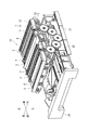
図1は本発明の一実施形態となる清掃機構1を備えた光走査装置10を斜め上方から見た斜視図、図2は本発明の一実施形態となる清掃機構1の概略構成を示す拡大図である。
FIG. 1 is a perspective view of an
光走査装置10は、電子写真方式を採用する複写機、プリンタ、複合機等の画像形成装置に備えられる。本実施形態では、光走査装置10として、マゼンタ、シアン、イエロー、黒用に4つの感光体ドラムを並設するカラー画像形成装置に備えられるレーザー・スキャニング・ユニット(LSU)を示している。光走査装置10の筐体2内には、上記4つの感光体ドラム表面を露光するためにレーザー光を出射する4つの走査光学系が並設されて収容されている。
The
筐体2には、4つの走査光学系からそれぞれ出射されるレーザー光が通過するための矩形の細長い4つの出射口3が形成されている。各出射口3は光を透過する透明な細長い防塵ガラス4によって覆われている。各出射口3及び防塵ガラス4は、各感光体にレーザー光が照射される主走査方向(図1の左右方向)に延びる形状を有し、各防塵ガラス4の表面は清掃機構1によって清掃される。清掃機構1は、隣接する2つの防塵ガラス4を清掃可能に設けられている。
The
清掃機構1は、スクリュー軸11と、清掃部材12と、保持部材13と、上下2段のガイドレール部材14(図2参照)とを備えている。
The
筐体2には、上記主走査方向(図1の左右方向)に延びるスクリュー軸11が配設されている。スクリュー軸11は、その回転軸が、駆動機構(詳細は後述)と接続する側の側端部が軸受に軸支されている。
The
図2は、清掃機構1の概略構成を示す拡大図であり、図1に示した4つの防塵ガラス4のうちの1つ(図1の一番手前側)を示す。
FIG. 2 is an enlarged view showing a schematic configuration of the
清掃部材12は、弾性を有するブレード部材(シリコンパッド)等で構成されており、防塵ガラス4上に配置される。
The
清掃部材12を保持する保持部材13は、円柱形状であり、スクリュー軸11に嵌合されて一体的に設けられている。清掃部材12は、保持部材13に保持されているため、保持部材13と同一方向、すなわち、防塵ガラス4表面上を主走査方向(図2の左右方向)に往復移動する。
The
上下2段のガイドレール部材14は、上側ガイドレール15と、下側ガイドレール16とを有する。
The upper and lower
保持部材13の端部は、上下2段のガイドレール部材14に軸支され、これにより保持部材13の移動方向が規制される。なお、図2では、保持部材13の一端(図面奥側)のみ示したが、保持部材13の他端(図面手前側)も、図示しない上下2段のガイドレール部材に軸支されている。これにより、保持部材13は、防塵ガラス4表面上を主走査方向(図1の左右方向)に往復移動可能となる。
The end portion of the
次に、光走査装置10の清掃機構1の駆動機構(移動機構)について説明する。
Next, the drive mechanism (movement mechanism) of the
図1に示すように、駆動機構は、ラック歯21と、ピニオンギア22と、ギア23とを備える。
As shown in FIG. 1, the drive mechanism includes
ラック歯21は、給紙カセット30の側面に設けられている。給紙カセット30は、画像形成装置に対して挿抜可能となっている。給紙カセット30には、通常用紙が収容されている。
The
スクリュー軸11の端部(図1の手前側)には、ギア23が固定されており、スクリュー軸11と一体的に回転するようになっている。
A
ラック歯21およびギア23に噛み合うピニオンギア22を設け、ピニオンギア22を正回転または逆回転させることにより、スクリュー軸11を回転駆動させる。
A
ギア23は、ピニオンギア22と噛合しており、給紙カセット30の挿抜動作により、ラック歯21が駆動すると、ピニオンギア22に噛合するギア23が回転して、スクリュー軸11が所定方向に回転するようになっている。スクリュー軸11は、ピニオンギア22からの回転駆動力によって回転駆動される。このようにして、給紙カセット30の挿抜動作による回転駆動力は、スクリュー軸11まで伝達される。
The
次に、本実施形態における光走査装置10の清掃機構について説明する。
清掃前の状態においては、通常、給紙カセット30は、画像形成装置の一番奥まで押し込まれて閉じている。この場合、清掃部材12を保持する保持部材13は、上側ガイドレール15の端部15A(図2の右側)に位置している。
Next, the cleaning mechanism of the
In the state before cleaning, the
次に、ユーザーが給紙カセット30を一番手前まで引き抜く(往路)と、給紙カセット30の引き抜き動作に連動してラック歯21が駆動し、これに噛合するピニオンギア22の回転がギア23を介してスクリュー軸11に伝達する。すると、スクリュー軸11と嵌合する保持部材13が、上側ガイドレール15の端部15A(図2の右側)から上側ガイドレール15に沿って端部15B(図2の左側)まで移動し、最終的に下側ガイドレール16の端部16B(図2の左側)まで移動する。
Next, when the user pulls out the
この往路では、保持部材13に取り付けた清掃部材12は、防塵ガラス4表面に接触していないため、防塵ガラス4の清掃は行われない。
In this outward path, since the cleaning
続いて、手前まで引き抜かれた状態の給紙カセット30を、ユーザーが一番奥まで押し込むと(復路)、給紙カセット30の押し込み動作に連動してラック歯21が駆動し、これに噛合するピニオンギア22の回転がギア23を介してスクリュー軸11に伝達する。すると、スクリュー軸11と嵌合した保持部材13が、下側ガイドレール16の端部16B(図2の左側)から下側ガイドレール16に沿って端部16A(図2の右側)まで移動い、最終的に上側ガイドレール15の端部15A(清掃前の元の位置)まで移動する。
Subsequently, when the user pushes in the
この復路では、保持部材13に取り付けた清掃部材12は、防塵ガラス4表面に直接接触する。清掃部材12を保持する保持部材13は、防塵ガラス4表面上を主走査方向に移動するため、清掃部材12により防塵ガラス4表面の清掃が行われる。
In this return path, the cleaning
ところで、給紙カセット30の挿抜が中途半端な位置で、ユーザーが給紙カセット30を挿抜すると、防塵ガラス4表面上に清掃部材12が接している場合には、防塵ガラス4表面上にトナー等の拭き残し、及び拭きムラが発生する可能性がある。しかし、本実施形態によれば、給紙カセット30の移動動作の往路ではなく復路において、防塵ガラス4に清掃部材12が接触するようにしているため、防塵ガラス4表面でのトナーの拭きムラの発生を抑制することができる。これは、ユーザーは給紙カセット30に用紙を補充した後、給紙カセット30を必ず一番奥まで押し込むためである。
By the way, when the user inserts / removes the
上記実施形態においては、ユーザーが行う給紙カセット30の挿抜動作に連動させて、自動的に駆動機構が駆動して清掃が行われるようにしたが、これに限定されず、駆動機構を駆動させる操作ボタンを設けることもできる。例えば、ユーザーが清掃用メカ式ボタンを押圧することにより、駆動機構が駆動して清掃が行われるようにすることもできる。この場合、単なる用紙補給時には、給紙カセット30の挿抜を行っても清掃が行われないため、より効率的に防塵ガラス4表面の清掃を行うことができる。なお、清掃用メカ式ボタンは、例えば、タッチパネル式の操作パネル上に表示させることができる。
In the above embodiment, the drive mechanism is automatically driven to perform cleaning in conjunction with the insertion / extraction operation of the
なお、本実施形態においては、給紙カセット30の移動動作の往路で清掃部材12を防塵ガラス4表面に接触させずに、復路で清掃部材12を防塵ガラス4表面に接触させて防塵ガラス4の清掃を行わせるようにしたが、往路と復路で清掃を逆にすることもできる。例えば、給紙カセット30の移動動作の往路で清掃部材12を防塵ガラス4表面に接触させて防塵ガラス4の清掃を行わせるようにし、復路で清掃部材12を防塵ガラス4表面に接触させないようにすることもできる。この場合、例えば、4つの清掃機能のうち、2つは往路で清掃、2つを復路で清掃するようにすれば、清掃のための駆動の負担を分散することができる。
In the present embodiment, the cleaning
なお、ラック歯21、ピニオンギア22、ギア23は駆動機構一例であり、他の駆動機構(移動機構)を使用することもできる。
The
今回開示された実施形態は、すべての点で例示であって、制限的なものではないと考えられるべきである。本発明の範囲は、上記実施形態の説明ではなく特許請求の範囲によって示され、さらに、特許請求の範囲と均等の意味及び範囲内でのすべての変更が含まれる。 It should be thought that embodiment disclosed this time is an illustration and restrictive at no points. The scope of the present invention is shown not by the above description of the embodiment but by the scope of claims for patent, and further includes all modifications within the meaning and scope equivalent to the scope of claims for patent.
本発明に係る防塵ガラスの清掃機構は、光走査装置を備えた画像形成装置(例えば複写機、プリンタ、ファクシミリ等)に適用可能である。 The dust-proof glass cleaning mechanism according to the present invention is applicable to an image forming apparatus (for example, a copying machine, a printer, a facsimile machine, etc.) provided with an optical scanning device.
1 清掃機構
3 出射口
4 防塵ガラス
10 光走査装置
11 スクリュー軸
12 清掃部材
13 保持部材
14 上下2段のガイドレール部材
15 上側ガイドレール
16 下側ガイドレール
21 ラック歯
22 ピニオンギア
23 ギア
30 給紙カセット
DESCRIPTION OF
Claims (8)
ユーザーが行う画像形成装置への給紙カセット挿抜の動作に連動して回転するスクリュー軸と、
前記スクリュー軸を正逆転させて前記防塵ガラス表面上を主走査方向に往復移動して当該防塵ガラス表面を清掃する清掃部材と、
前記清掃部材を保持する保持部材と、
前記保持部材の主走査方向への移動を規制する、上側ガイドレールおよび下側ガイドレールを有する上下2段のガイドレール部材と、を備えることを特徴とする清掃機構。 An optical scanning device in which a plurality of scanning optical systems that emit light for writing a latent image to an image carrier are accommodated in a frame, and the light emission ports emitted from the respective scanning optical systems are covered with dust-proof glass A cleaning mechanism for cleaning the dust-proof glass,
A screw shaft that rotates in conjunction with the operation of inserting and removing the paper cassette into the image forming apparatus performed by the user,
A cleaning member that cleans the dust-proof glass surface by reciprocating in the main scanning direction on the dust-proof glass surface by rotating the screw shaft forward and backward,
A holding member for holding the cleaning member;
A cleaning mechanism comprising: upper and lower guide rail members having an upper guide rail and a lower guide rail for restricting movement of the holding member in the main scanning direction.
前記給紙カセットを抜く時(往路)は、前記上側ガイドレールにより前記保持部材の移動が規制され、
前記給紙カセットを挿入する時(復路)は、前記下側ガイドレールにより前記保持部材の移動が規制される、ことを特徴とする清掃機構。 The cleaning mechanism according to claim 1,
When the paper cassette is pulled out (outward), the movement of the holding member is restricted by the upper guide rail,
A cleaning mechanism, wherein when the paper feed cassette is inserted (return path), movement of the holding member is restricted by the lower guide rail.
前記清掃部材は、前記給紙カセットの往復動作の往路と復路とで、主走査方向への移動方向が逆となることを特徴とする清掃機構。 The cleaning mechanism according to claim 1 or 2,
The cleaning mechanism is characterized in that the moving direction in the main scanning direction is reversed between the forward path and the backward path of the reciprocating operation of the sheet feeding cassette.
前記給紙カセットの往復動作の往路および復路のいずれか一方のみ、前記清掃部材が防塵ガラス表面と接触することを特徴とする清掃機構。 In the cleaning mechanism according to any one of claims 1 to 3,
The cleaning mechanism, wherein the cleaning member is in contact with the surface of the dust-proof glass only in one of the forward path and the return path of the reciprocating operation of the paper feed cassette.
画像形成装置本体に対して挿抜可能な給紙カセットと、
前記給紙カセット挿抜の動作に連動して駆動する駆動機構とを備え、
前記駆動機構は、前記給紙カセットの側面に設けられるラック歯と、
前記スクリュー軸を回転駆動させるギアと、
前記ラック歯およびギアと噛合するピニオンギアとを有し、
前記給紙カセットの挿抜動作に連動して前記駆動機構が駆動し、防塵ガラス表面の清掃が行われる、ことを特徴とする画像形成装置。 The image forming apparatus according to claim 6.
A paper feed cassette that can be inserted into and removed from the image forming apparatus body;
A drive mechanism that is driven in conjunction with the operation of inserting and removing the paper cassette;
The drive mechanism includes rack teeth provided on a side surface of the paper feed cassette;
A gear for rotationally driving the screw shaft;
A pinion gear meshing with the rack teeth and gear,
The image forming apparatus, wherein the driving mechanism is driven in conjunction with the insertion / extraction operation of the paper feed cassette to clean the surface of the dust-proof glass.
前記駆動機構を駆動させて防塵ガラス表面の清掃を実行する操作ボタンを備える、ことを特徴とする画像形成装置。 The image forming apparatus according to claim 6 or 7,
An image forming apparatus comprising an operation button for driving the drive mechanism to execute cleaning of the dust-proof glass surface.
Priority Applications (1)
| Application Number | Priority Date | Filing Date | Title |
|---|---|---|---|
| JP2014128916A JP2016007745A (en) | 2014-06-24 | 2014-06-24 | Cleaning mechanism, and optical scanner and image forming apparatus using the same |
Applications Claiming Priority (1)
| Application Number | Priority Date | Filing Date | Title |
|---|---|---|---|
| JP2014128916A JP2016007745A (en) | 2014-06-24 | 2014-06-24 | Cleaning mechanism, and optical scanner and image forming apparatus using the same |
Publications (1)
| Publication Number | Publication Date |
|---|---|
| JP2016007745A true JP2016007745A (en) | 2016-01-18 |
Family
ID=55225675
Family Applications (1)
| Application Number | Title | Priority Date | Filing Date |
|---|---|---|---|
| JP2014128916A Pending JP2016007745A (en) | 2014-06-24 | 2014-06-24 | Cleaning mechanism, and optical scanner and image forming apparatus using the same |
Country Status (1)
| Country | Link |
|---|---|
| JP (1) | JP2016007745A (en) |
Cited By (4)
| Publication number | Priority date | Publication date | Assignee | Title |
|---|---|---|---|---|
| EP3305169A1 (en) | 2016-10-05 | 2018-04-11 | Fujifilm Corporation | Endoscope system and method of driving endoscope system |
| CN109073880A (en) * | 2016-05-25 | 2018-12-21 | 京瓷办公信息系统株式会社 | Optical scanning device and image forming device having the same |
| US10551615B2 (en) | 2016-09-29 | 2020-02-04 | Kyocera Document Solutions Inc | Casing of optical scanning device |
| CN116448581A (en) * | 2023-06-19 | 2023-07-18 | 山东力达智能车辆产业技术研究院有限公司 | Car as a house glass compressive strength detection device |
-
2014
- 2014-06-24 JP JP2014128916A patent/JP2016007745A/en active Pending
Cited By (7)
| Publication number | Priority date | Publication date | Assignee | Title |
|---|---|---|---|---|
| CN109073880A (en) * | 2016-05-25 | 2018-12-21 | 京瓷办公信息系统株式会社 | Optical scanning device and image forming device having the same |
| US10324411B2 (en) | 2016-05-25 | 2019-06-18 | Kyocera Document Solutions Inc. | Optical scanning device and image forming apparatus including the same |
| US10551615B2 (en) | 2016-09-29 | 2020-02-04 | Kyocera Document Solutions Inc | Casing of optical scanning device |
| EP3305169A1 (en) | 2016-10-05 | 2018-04-11 | Fujifilm Corporation | Endoscope system and method of driving endoscope system |
| US10820786B2 (en) | 2016-10-05 | 2020-11-03 | Fujifilm Corporation | Endoscope system and method of driving endoscope system |
| CN116448581A (en) * | 2023-06-19 | 2023-07-18 | 山东力达智能车辆产业技术研究院有限公司 | Car as a house glass compressive strength detection device |
| CN116448581B (en) * | 2023-06-19 | 2023-09-05 | 山东力达智能车辆产业技术研究院有限公司 | Car as a house glass compressive strength detection device |
Similar Documents
| Publication | Publication Date | Title |
|---|---|---|
| US8831468B2 (en) | Optical scanner and image forming device | |
| JP5931011B2 (en) | Optical scanning apparatus and image forming apparatus | |
| JP5208298B2 (en) | Image forming apparatus | |
| JP2016218164A (en) | Developing device, image forming apparatus, and process cartridge | |
| JP5597675B2 (en) | Image forming apparatus | |
| JP6418405B2 (en) | Optical scanning device and image forming apparatus including the optical scanning device | |
| JP6232956B2 (en) | Image forming apparatus and dust-proof cover cleaning member | |
| JP2011013306A (en) | Image forming apparatus | |
| JP5253479B2 (en) | Image forming apparatus drive unit and image forming apparatus using the same | |
| JP5108540B2 (en) | Automatic cleaning mechanism and optical scanning device having the same | |
| JP2018165037A (en) | Optical scanning device and image forming apparatus including the optical scanning device | |
| JP2019045762A (en) | Illuminating device, drum unit, image forming apparatus provided with illuminating device, and image reading device | |
| CN107797413B (en) | Optical scanning device and image forming apparatus including the same | |
| JP2005024661A (en) | Cleaning device, process cartridge, and image forming apparatus | |
| JP2018001433A (en) | Optical scanning device and image forming apparatus including the optical scanning device | |
| JP6056693B2 (en) | Exposure apparatus and image forming apparatus | |
| JP4921869B2 (en) | Cleaning mechanism for light transmission member of scanning optical device, scanning optical device | |
| JP6702260B2 (en) | Optical scanning device, image forming apparatus, and optical scanning method | |
| JP2011180164A (en) | Electrifying device and image-forming device equipped with the same | |
| JPWO2018155200A1 (en) | Reciprocating mechanism of moving body, cleaning mechanism, light scanning device and image forming apparatus | |
| JP5807099B2 (en) | Image forming apparatus | |
| JP5638161B2 (en) | Image forming apparatus | |
| JP2006106631A (en) | Light beam scanning apparatus and image forming apparatus | |
| JP4067430B2 (en) | Charger cleaning device | |
| JP2005017902A (en) | Optical system unit cleaning device |