JP2016007772A - Tape printer, printed tape roll, and tape printing program - Google Patents
Tape printer, printed tape roll, and tape printing program Download PDFInfo
- Publication number
- JP2016007772A JP2016007772A JP2014129664A JP2014129664A JP2016007772A JP 2016007772 A JP2016007772 A JP 2016007772A JP 2014129664 A JP2014129664 A JP 2014129664A JP 2014129664 A JP2014129664 A JP 2014129664A JP 2016007772 A JP2016007772 A JP 2016007772A
- Authority
- JP
- Japan
- Prior art keywords
- tape
- image
- printed
- printing
- Prior art date
- Legal status (The legal status is an assumption and is not a legal conclusion. Google has not performed a legal analysis and makes no representation as to the accuracy of the status listed.)
- Granted
Links
- 238000007639 printing Methods 0.000 claims abstract description 64
- 230000015572 biosynthetic process Effects 0.000 claims abstract description 32
- 238000004804 winding Methods 0.000 claims description 68
- 238000000034 method Methods 0.000 claims description 42
- 239000000463 material Substances 0.000 claims description 26
- 230000002093 peripheral effect Effects 0.000 claims description 11
- 238000003860 storage Methods 0.000 description 47
- 239000010410 layer Substances 0.000 description 44
- 230000008569 process Effects 0.000 description 25
- 230000007246 mechanism Effects 0.000 description 23
- 238000005520 cutting process Methods 0.000 description 12
- 238000012986 modification Methods 0.000 description 12
- 230000004048 modification Effects 0.000 description 12
- 230000000052 comparative effect Effects 0.000 description 10
- 239000002390 adhesive tape Substances 0.000 description 9
- 239000012790 adhesive layer Substances 0.000 description 7
- 238000004519 manufacturing process Methods 0.000 description 7
- 239000000853 adhesive Substances 0.000 description 6
- 230000001070 adhesive effect Effects 0.000 description 6
- 230000000694 effects Effects 0.000 description 6
- 239000004820 Pressure-sensitive adhesive Substances 0.000 description 3
- 238000010438 heat treatment Methods 0.000 description 3
- 238000011144 upstream manufacturing Methods 0.000 description 3
- 238000013461 design Methods 0.000 description 2
- 238000012545 processing Methods 0.000 description 2
- 230000004044 response Effects 0.000 description 2
- 238000013459 approach Methods 0.000 description 1
- 238000005452 bending Methods 0.000 description 1
- 230000008859 change Effects 0.000 description 1
- 238000004891 communication Methods 0.000 description 1
- 238000012217 deletion Methods 0.000 description 1
- 230000037430 deletion Effects 0.000 description 1
- 238000010586 diagram Methods 0.000 description 1
- 238000012546 transfer Methods 0.000 description 1
- 239000002699 waste material Substances 0.000 description 1
- 230000037303 wrinkles Effects 0.000 description 1
Images









Landscapes
- Printers Characterized By Their Purpose (AREA)
- Electronic Switches (AREA)
- Record Information Processing For Printing (AREA)
Abstract
Description
本発明は、被印字テープに所望の画像を形成するテープ印刷装置、このテープ印刷装置により生成される印字済みテープロール、及びテープ印刷装置において使用されるテープ印刷プログラムに関する。 The present invention relates to a tape printer that forms a desired image on a tape to be printed, a printed tape roll generated by the tape printer, and a tape printing program used in the tape printer.
被印字テープに所望の印字内容の画像を形成するテープ印刷装置が知られている(例えば、特許文献1参照)。このテープ印刷装置では、搬送手段(搬送用ローラ)が回転駆動されることで、被印字テープロール(第1ロール)から被印字テープ(被印字粘着テープ)が繰り出されて搬送され、その搬送される被印字テープに対し、印字手段(印字ヘッド)が所望の画像を形成する。画像が形成された印字済みテープ(印字済み粘着テープ)は、巻芯(第3巻芯部材)のまわりに順次巻き取られることで、ロール状に巻回される。 2. Description of the Related Art A tape printing apparatus that forms an image with a desired print content on a print-receiving tape is known (for example, see Patent Document 1). In this tape printing apparatus, the printing means (printing adhesive tape) is fed out from the printing tape roll (first roll) and conveyed by the conveyance means (conveying roller) being driven to rotate. The printing means (printing head) forms a desired image on the print-receiving tape. The printed tape (printed adhesive tape) on which an image is formed is wound into a roll shape by being sequentially wound around a core (third core member).
上記のようにして印字済みテープがロール状に巻回される場合、ロール中において巻回された状態では上記画像の内容をユーザが確認しづらく、不便な場合があった。また、ロール状になっていない場合でも、印字済みテープが曲がっていたり丸まっている等の場合には、上記画像の内容を確認するためにユーザが手元で長く伸ばし広げなければならない場合があり、上記同様、不便であった。 When the printed tape is wound in a roll shape as described above, it may be inconvenient because it is difficult for the user to confirm the content of the image when the tape is wound in the roll. In addition, even if it is not in the form of a roll, if the printed tape is bent or rounded, the user may have to stretch it long at hand to check the contents of the image, As above, it was inconvenient.
本発明の目的は、印字済みテープに形成されている画像の内容を容易に確認でき、ユーザの利便性を向上できるテープ印刷装置、及び印字済みテープロール、並びにテープ印刷プログラムを提供することにある。 An object of the present invention is to provide a tape printing apparatus, a printed tape roll, and a tape printing program that can easily confirm the contents of an image formed on a printed tape and improve user convenience. .
上記目的を達成するために、本願発明は、 被印字テープロールから被印字テープを繰り出して搬送する搬送手段と、前記搬送手段を回転駆動する駆動力を発生する搬送用駆動手段と、前記搬送手段により搬送される前記被印字テープに対し、印字を形成する印字手段と、前記印字手段による印字形成のための印字データを取得するデータ取得手段と、前記データ取得手段により取得された前記印字データに対応した第1画像、及び、前記第1画像を縮小した第2画像、を共に前記被印字テープに印字形成するように、前記搬送用駆動手段及び前記印字手段を連携して制御する連携制御手段と、を有することを特徴とする。 In order to achieve the above-mentioned object, the present invention includes a conveying unit that feeds and conveys a print-receiving tape from a print-receiving tape roll, a conveying drive unit that generates a driving force for rotationally driving the conveying unit, and the conveying unit. Printing means for forming prints on the tape to be printed conveyed by the printer, data acquisition means for acquiring print data for print formation by the printing means, and the print data acquired by the data acquisition means Cooperation control means for controlling the transport driving means and the printing means in a coordinated manner so that the corresponding first image and the second image obtained by reducing the first image are both printed on the print-receiving tape. It is characterized by having.
本願発明のテープ印刷装置においては、搬送用駆動手段の駆動力によって搬送手段が回転駆動されることで、被印字テープロールから被印字テープが繰り出されて搬送され、その搬送される被印字テープに対し、印字手段が所望の画像を形成する。 In the tape printer of the present invention, the transporting means is driven to rotate by the driving force of the transporting drive means, so that the print-receiving tape is fed out and transported from the print-receiving tape roll. On the other hand, the printing means forms a desired image.
その画像形成の際、本願発明においては、連携制御手段の制御により、第1画像と第2画像との2種類が、被印字テープに形成される。第1画像は、例えばユーザが被印字テープに印字形成したい本来の印字内容である。すなわち、この第1画像は、データ取得手段によって取得された印字データに対応する画像である。一方、第2画像は、上記第1画像を(例えば縦横比が同じ倍率で)縮小した画像であり、上記取得された印字データに基づき第1画像が(装置内部で)生成されるときに、併せて第2画像も生成される。 In forming the image, in the present invention, two types of the first image and the second image are formed on the print-receiving tape under the control of the cooperation control unit. The first image is the original print content that the user wants to print on the print-receiving tape, for example. That is, the first image is an image corresponding to the print data acquired by the data acquisition unit. On the other hand, the second image is an image obtained by reducing the first image (for example, with the same aspect ratio), and when the first image is generated (inside the apparatus) based on the acquired print data, In addition, a second image is also generated.
以上の結果、上記のようにして印字形成が行われた後のテープ(印字済みテープ)には、ユーザが意図する画像(第1画像)に加え、その縮小版画像(第2画像)も形成されていることとなる。これにより、ユーザは、上記印字済みテープに形成された上記第1画像を長さ方向全長にわたって見なくても、上記第2画像部分を見るだけで、当該第1画像の内容を確認することができる。この結果、ユーザの利便性を向上することができる。 As a result, in addition to the image (first image) intended by the user, the reduced version image (second image) is also formed on the tape (printed tape) after the printing is formed as described above. Will be. Thus, the user can confirm the contents of the first image by merely looking at the second image portion without looking at the first image formed on the printed tape over the entire length in the length direction. it can. As a result, user convenience can be improved.
特に、印字済みテープに形成された上記第1画像の長さ(印刷長さ)がテープ長さ方向に沿って比較的長い場合には、第1画像の内容を確認するためには、印字済みテープをユーザの手元で長く伸ばし広げた状態とする必要がある。これに対し、第2画像は、第1画像を縮小したものであることから、上記操作を行う必要なく、容易に内容を確認することができる。さらに、印字済みテープがロール状に巻回されて印字済みテープロールとされる場合には、ロール中において巻回された状態では特に上記第1画像の確認がしづらくなるので、上述した第2画像の容易な視認性が特に効果的である。 In particular, when the length (printing length) of the first image formed on the printed tape is relatively long along the tape length direction, the printed image is used to confirm the content of the first image. It is necessary to keep the tape long stretched at the user's hand. On the other hand, since the second image is a reduced version of the first image, the contents can be easily confirmed without performing the above operation. Further, when the printed tape is wound into a roll to form a printed tape roll, it is difficult to confirm the first image particularly in the state of being wound in the roll. Easy visibility of the image is particularly effective.
本発明によれば、印字済みテープに形成されている画像の内容を容易に確認でき、ユーザの利便性を向上することができる。 According to the present invention, the content of an image formed on a printed tape can be easily confirmed, and user convenience can be improved.
以下、本発明の実施の形態について図面を参照しつつ説明する。なお、図面中に「前方」「後方」「左方」「右方」「上方」「下方」の注記がある場合は、明細書中の説明における「前方(前)」「後方(後)」「左方(左)」「右方(右)」「上方(上)」「下方(下)」とは、その注記された方向を指す。 Embodiments of the present invention will be described below with reference to the drawings. In addition, when there are notes “front”, “rear”, “left”, “right”, “upper”, “lower” in the drawings, “front (front)” “rear (rear)” in the description in the specification “Left (left)”, “right (right)”, “upper (upper)” and “lower (lower)” refer to the noted direction.
<第1実施形態>
本発明の第1実施形態を図1〜21により説明する。
<First Embodiment>
A first embodiment of the present invention will be described with reference to FIGS.
<テープ印刷装置の概略構成>
まず、図1〜図4を参照しつつ、本実施形態によるテープ印刷装置の概略構成について説明する。
<Schematic configuration of tape printer>
First, the schematic configuration of the tape printer according to the present embodiment will be described with reference to FIGS.
<筐体>
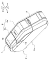
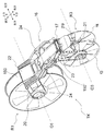
図1〜図4において、本実施形態のテープ印刷装置1は、装置外郭を構成する筐体2を有している。筐体2は、筐体本体2aと、後方側開閉部8と、前方側開閉カバー9と、を備えている。
<Case>
1-4, the
筐体本体2a内には、後方側に設けられた第1収納部3と、前方側に設けられた第2収納部5及び第3収納部4と、が備えられている。
The housing
後方側開閉部8は、筐体本体2aの後方側の上部に対し開閉可能に接続されている。この後方側開閉部8は、回動することで、第1収納部3の上方を開閉可能である。この後方側開閉部8は、第1開閉カバー8a及び第2開閉カバー8bにより構成されている。
The rear side opening /
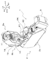
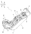
第1開閉カバー8aは、筐体本体2aの後方側の上部に設けられた所定の回動軸心K1まわりに回動することで、第1収納部3のうち前方側の上方を開閉可能である。詳細には、第1開閉カバー8aは、第1収納部3のうち前方側の上方を覆う閉じ位置(図1、図2の状態)から、第1収納部3のうち前方側の上方を露出させる開き位置(図3、図4の状態)までの間で回動可能である。
The first opening /
第1開閉カバー8aの内部には、ヘッド保持部10が設けられている(図3も参照)。そして、第1開閉カバー8aは、上記の回動軸心K1まわりに回動することで、ヘッド保持部10に備えられた印字ヘッド11(印字手段に相当)を、筐体本体2aに設けられた搬送ローラ12(搬送手段に相当)に対して相対的に離反・近接可能である。すなわち、第1開閉カバー8aの上記閉じ位置(図1、図2の状態)では印字ヘッド11が搬送ローラ12に対して近接し、第1開閉カバー8aの上記開き位置(図3、図4の状態)では、印字ヘッド11が搬送ローラ12から離反する。
A
第2開閉カバー8bは、上記第1開閉カバー8aよりも後方側に設けられており、筐体本体2aの後方側の上端部に設けられた所定の回動軸心K2まわりに回動することで、第1収納部3のうち後方側の上方を、上記第1開閉カバー8aの開閉とは別個に開閉可能である。詳細には、第2開閉カバー8bは、第1収納部3のうち後方側の上方を覆う閉じ位置(図1及び図2の状態)から、第1収納部3のうち後方側の上方を露出させる開き位置(図3及び図4の状態)までの間で回動可能である。
The second opening /
そして、これら第1開閉カバー8a及び第2開閉カバー8bは、それぞれが閉じ状態であるときに、当該第1開閉カバー8aの外周部18と当該第2開閉カバー8bの縁部19とが互いに略接触して、第1収納部3の上方の略全部を覆うように構成されている。
When the first opening /
前方側開閉カバー9は、筐体本体2aの前方側の上部に対し開閉可能に接続されている。この前方側開閉カバー9は、筐体本体2aの前方側の上端部に設けられた所定の回動軸心K3まわりに回動することで、第3収納部4の上方を開閉可能である。詳細には、前方側開閉カバー9は、第3収納部4の上方を覆う閉じ位置(図1、図2の状態)から、第3収納部4の上方を露出させる開き位置(図3、図4の状態)までの間で回動可能である。
The front side opening /
<被印字テープロール及びその周辺>
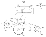
このとき、図2〜図4に示すように、筐体本体2aにおける、閉じ状態での前方側開閉カバー9の下方にある第1所定位置13には、テープカートリッジTK(図2参照)が着脱可能に装着される。このテープカートリッジTKは、軸心O1まわりに巻回形成された第1ロールR1(被印字テープロールに相当)を備えている。
<Printed tape roll and its surroundings>
At this time, as shown in FIGS. 2 to 4, the tape cartridge TK (see FIG. 2) is attached to and detached from the first
すなわち、テープカートリッジTKは、図5に示すように、第1ロールR1と、連結アーム16とを備えている。連結アーム16は、後方側に設けられた左・右一対の第1ブラケット部20,20と、前方側に設けられた左・右一対の第2ブラケット部21,21とを備えている。
That is, the tape cartridge TK includes a first roll R1 and a connecting
第1ブラケット部20,20は、上記第1ロールR1を、軸心O1に沿った左・右両側から挟みこむようにし、テープカートリッジTKが筐体本体2aに装着された状態では第1ロールR1を巻芯39(後述の図11〜図15等も参照)当該軸心O1まわりに回転可能に保持する。これら第1ブラケット部20,20は、上端部において左右方向に略沿って延設された第1接続部22により第1ロールR1の外径との干渉を回避しつつ接続されている。
The
第1ロールR1は、テープカートリッジTKが筐体本体2aの内部に装着された際には回転自在となる。第1ロールR1は、繰り出しにより消費される被印字テープ150(後述する被印字層154、基材層153、粘着剤層152、剥離材層151を備える。図2中拡大図参照)を、左右方向の上記軸心O1を備えた上記巻芯39まわりに予め巻回している。
The first roll R1 is rotatable when the tape cartridge TK is mounted inside the
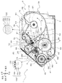
第1収納部3には、上記テープカートリッジTKの装着によって、第1ロールR1が上方から受け入れられ、被印字テープ150の巻回の軸心O1が左右方向となる状態で収納される。そして、第1ロールR1は、第1収納部3に収納された状態(テープカートリッジTKが装着された状態)において当該第1収納部3内で所定の回転方向(図2中のA方向)に回転することで、被印字テープ150を繰り出す。
When the tape cartridge TK is mounted, the first roll R1 is received from above and is stored in the
本実施形態では、粘着性を備えた被印字テープ150が用いられる場合を例示している。すなわち、被印字テープ150は、被印字層154、基材層153、粘着剤層152、剥離材層151が、厚さ方向一方側(図2中の上方側)から他方側(図2中の下方側)へ向かって、この順序で積層されている。被印字層154は、上記印字ヘッド11によるインクの熱転写によって、ユーザが印字形成を意図する所望の第1画像155(図2中の部分拡大図及び後述の図7等を参照)が形成される層である。粘着剤層152は、基材層153を適宜の被着体(図示省略)に貼り付けるための層である。剥離材層151は、粘着剤層152を覆う層である。
In this embodiment, the case where the to-
<搬送ローラ及び印字ヘッド>
図2〜図4に戻り、筐体本体2aにおける第1収納部3及び第2収納部5の中間上方側には、上記搬送ローラ12が設けられている。搬送ローラ12は、筐体本体2aの内部に設けられた搬送用モータM1(搬送用駆動手段に相当)によりギア機構(図示省略)を介して回転駆動されることで、第1収納部3に収納された第1ロールR1から繰り出される被印字テープ150を、テープ幅方向が左右方向となるテープ姿勢で搬送する。
<Conveyance roller and print head>
2 to 4, the
また、第1開閉カバー8aに設けられた上記ヘッド保持部10には、上記印字ヘッド11が備えられている。印字ヘッド11は、上述したように、第1開閉カバー8aが回動軸心K1まわりに回動することで、搬送ローラ12に対して相対的に離間・近接可能である。すなわち、第1開閉カバー8aが閉じ状態となると、印字ヘッド11が搬送ローラ12に近接し、第1開閉カバー8aが開き状態となると、印字ヘッド11が搬送ローラ12から離間する。この印字ヘッド11は、搬送ローラ12により搬送される被印字テープ150を当該搬送ローラ12と協働して挟持するように、ヘッド保持部10のうち閉じ状態での第1開閉カバー8aにおいて搬送ローラ12の上方に対向する位置に配置されている。したがって、第1開閉カバー8aが閉じ状態である場合には、印字ヘッド11と搬送ローラ12とは、互いに上下方向に対向して配置される。そして、印字ヘッド11は、搬送ローラ12との間に挟まれた状態の被印字テープ150の被印字層154に対し、後述するインクリボンカートリッジRKのインクリボンIBを用いて上記第1画像155を形成して、印字済みテープ150′とする。
In addition, the
<インクリボンカートリッジ>
図2及び図3に示すように、筐体本体2aにおける閉じ状態での第1開閉カバー8aの下方でかつテープカートリッジTKの上方となる第2所定位置14には、インクリボンカートリッジRKが着脱可能に装着される。このインクリボンカートリッジRKは、未使用のインクリボンIBを繰り出し可能に巻回したリボン繰り出しロールR4と、リボン巻き取りロールR5とを備えている。インクリボンカートリッジRKは、後方側の繰り出しロール収納部81と、前方側の巻き取りロール収納部82と、が中央の連結部(図示省略)によって連結されている。連結部は、リボン繰り出しロールR4から繰り出された上記インクリボンIBをインクリボンカートリッジRK外に露出させるようにしつつ、上記巻き取りロール収納部82と上記繰り出しロール収納部81とを連結する。
<Ink ribbon cartridge>
As shown in FIGS. 2 and 3, the ink ribbon cartridge RK is detachable at a second predetermined position 14 below the first opening /
リボン繰り出しロールR4は、繰り出しロール収納部81内において回転自在に支持されており、インクリボンカートリッジRKが装着された状態において所定の回転方向(図2中のD方向)に回転することで、印字ヘッド11による印字形成を行うためのインクリボンIBを繰り出す。
The ribbon feeding roll R4 is rotatably supported in the feeding
リボン巻き取りロールR5は、巻き取りロール収納部82内において回転自在に支持されており、インクリボンカートリッジRKが装着された状態において所定の回転方向(図2中のE方向)に回転することで、印字形成後の使用済みのインクリボンIBを巻き取る。
The ribbon take-up roll R5 is rotatably supported in the take-up
すなわち、図2において、リボン繰り出しロールR4から繰り出されるインクリボンIBは、印字ヘッド11と搬送ローラ12との間に挟まれた状態の被印字テープ150のさらに印字ヘッド11側に配置されて印字ヘッド11の下方に接触する。そして、印字ヘッド11からの加熱によりインクリボンIBのインクが、被印字テープ150の被印字層154に転写されて第1画像155の形成が実行された後、使用済みのインクリボンIBが、リボン巻き取りロールR5に巻き取られる。
That is, in FIG. 2, the ink ribbon IB fed out from the ribbon feeding roll R4 is further arranged on the
<剥離材ロール及びその周辺>
図5に示すように、テープカートリッジTKの連結アーム16は、例えば略水平なスリット形状を含む引き剥がし部17を備えている。この引き剥がし部17は、第1ロールR1から繰り出されて前方側へと搬送される印字済みテープ150′から、剥離材層151を引き剥がす部位である。上記のようにして印字が形成された印字済みテープ150′は、図2に示すように、上記引き剥がし部17によって上記剥離材層151が引き剥がされることで、剥離材層151と、それ以外の被印字層154、基材層153及び粘着剤層152からなる印字済みテープ150″とに分離される。
<Release material roll and its periphery>
As shown in FIG. 5, the connecting
テープカートリッジTKは、図2及び図5に示すように、上記引き剥がされた剥離材層151が軸心O3を備えた巻芯29まわりに巻回されることで形成される、上記第3ロールR3を有している。すなわち、上述したテープカートリッジTKの装着によって、第3ロールR3が上方から上記第2収納部5に受け入れられ、軸心O3が左右方向となる状態で収納される。そして、巻芯29は、第2収納部5に収納された状態(テープカートリッジTKが装着された状態)において、筐体本体2a内に設けられた剥離紙巻取用モータM3によりギア機構(図示省略)を介して駆動され、第2収納部5内で所定の回転方向(図2中のC方向)に回転することで、剥離材層151を巻き取る。
As shown in FIGS. 2 and 5, the tape cartridge TK is formed by winding the peeled
このとき、図5に示すように、テープカートリッジTKの上記第2ブラケット部21,21は、上記第3ロールR3を、軸心O3に沿った左・右両側から挟みこむようにし、テープカートリッジTKが筐体本体2aに装着された状態では巻芯29(言い替えれば第3ロールR3)を当該軸心O3まわりに回転可能に保持する。これら第2ブラケット部21,21は、上端部において左右方向に略沿って延設された第2接続部23により接続されている。そして、後方側の第1ブラケット部20,20及び第1接続部22と、前方側の第2ブラケット部21,21及び第2接続部23とは、左・右一対のロール連結ビーム部24,24により連結されている。
At this time, as shown in FIG. 5, the
また、図5中では、巻芯29のまわりに剥離材層151が巻回され第3ロールR3が形成される前の状態(未使用のテープカートリッジTKである場合)を示している。すなわち、当該剥離材層151の幅方向両側を挟み込むように設けられている略円形の上記ロールフランジ部f3,f4を図示するとともに、便宜的に第3ロールR3が形成される箇所に符号「R3」を付している。
FIG. 5 shows a state before the
<印字済みテープロール及びその周辺>
一方、図2及び図4に示すように、上記第3収納部4には、上記印字済みテープ150″を順次巻回するための巻芯41(巻芯部材に相当)を備えた巻取機構40(巻取手段に相当)が上方から受け入れられる。巻取機構40は、印字済みテープ150″の巻回の軸心O2が左右方向となる状態で、上記巻芯41が軸心O2まわりに回転可能に支持されるように収納される。そして、巻取機構40が、第3収納部4に収納された状態において、筐体本体2aの内部に設けられた粘着巻取用モータM2(巻取用駆動手段に相当)により不図示のギア機構を介して巻芯41が駆動され、第3収納部4内で所定の回転方向(図2中のB方向)に回転することで、印字済みテープ150″を巻芯41の外周部に順次巻き取って積層する。これにより、巻芯41の外周側に印字済みテープ150″が(第1画像155及び後述の第2画像162が外周側となるようにしつつ)順次巻回されることで、第2ロールR2(印字済みテープロールに相当)が形成される。
<Printed tape roll and its surroundings>
On the other hand, as shown in FIGS. 2 and 4, a winding mechanism including a winding core 41 (corresponding to a winding core member) for sequentially winding the printed
<カッター機構>
また、図2に示すように、テープ搬送方向に沿って印字ヘッド11の下流側でかつ第2ロールR2の上流側に、カッター機構30が設けられている。
<Cutter mechanism>
As shown in FIG. 2, a
カッター機構30は、詳細な図示を省略するが、可動刃と、可動刃を支持しテープ幅方向(言い替えれば左右方向)に走行可能な走行体とを有している。そして、カッターモータMC(後述の図6参照)の駆動により走行体が走行し図示しない可動刃がテープ幅方向に移動することで、上記印字済みテープ150″を幅方向に切断する。
Although not shown in detail, the
<テープ印刷装置の動作の概略>
次に、上記構成のテープ印刷装置1の動作の概略について説明する。
<Outline of operation of tape printer>
Next, an outline of the operation of the
すなわち、上記第1所定位置13にテープカートリッジTKが装着されると、筐体本体2aの後方側に位置する第1収納部3に第1ロールR1が収納され、筐体本体2aの前方側に位置する第2収納部5に第3ロールR3を形成する軸心O3側が収納される。また、筐体本体2aの前方側に位置する第3収納部4には、第2ロールR2を形成するための巻取機構40が収納される。
That is, when the tape cartridge TK is mounted at the first
この状態で、ユーザが、被印字テープ150(この時点ではまだ印刷が始まっていない)から剥離材層151を手動で引き剥がし、基材層153及び粘着剤層152からなるテープの先端を、上記巻取機構40の巻芯41に取り付ける。そして、搬送ローラ12が駆動されると、第1収納部3に収納された第1ロールR1の回転により繰り出される被印字テープ150が、前方側へ搬送される。そして、搬送される被印字テープ150の被印字層154に対し、印字ヘッド11により所望の印字(上記第1画像155)が形成されて、印字済みテープ150′となる。印字形成された印字済みテープ150′は、さらに前方側へ搬送されて引き剥がし部17まで搬送されると、当該引き剥がし部17において剥離材層151が引き剥がされて印字済みテープ150″となる。引き剥がされた剥離材層151は、下方側へ搬送されて第2収納部5へ導入され、当該第2収納部5内において巻回されて第3ロールR3が形成される。
In this state, the user manually peels off the
一方、剥離材層151が引き剥がされた印字済みテープ150″は、さらに前方側へ搬送されて第3収納部4へ導入され、当該第3収納部4内の巻取機構40の巻芯41の外周側に巻回されて第2ロールR2が形成される。その際、搬送方向下流側(すなわち前方側)に設けられたカッター機構30が印字済みテープ150″を切断する。これにより、ユーザの所望のタイミングで、第2ロールR2に巻回されていく印字済みテープ150″を切断し、切断後は第2ロールR2を第3収納部4から取り出すことができる。なお、このようにして巻芯41の外周部にロール状に巻回された(第2ロールR2を形成している)印字済みテープ150″を、以下適宜「印刷物」と称する。
On the other hand, the printed
なおこのとき、図示による説明を省略するが、第1ロールR1に、非粘着テープ(上記粘着剤層152及び剥離材層151のないもの)が巻回されていても良い。この場合においても、第1収納部3には、テープカートリッジTKの装着によって、非粘着テープが巻回された第1ロールR1が上方から受け入れられ、非粘着テープの巻回の軸心O1が左右方向となる状態で収納される。そして、第1ロールR1は、第1収納部3に収納された状態(テープカートリッジTKが装着された状態)において当該第1収納部3内で所定の回転方向(図2中のA方向)に回転することで、非粘着テープを繰り出す。
In addition, although description by illustration is abbreviate | omitted at this time, the non-adhesive tape (The thing without the said
またこのとき、上記非粘着テープ(又は上記被印字テープ150でもよい)の搬送経路を、第2ロールR2へ向かう側と排出口(図示省略)へ向かう側との相互間で切り替える、シュート15(図2参照)が配されていても良い。すなわち、切替レバー(図示省略)によるシュート15の切替操作でテープ経路を切り替えることで、印字形成後の非粘着テープ(又は印字済みテープ150″)を上述のように第3収納部4内において巻回することなく、筐体2の例えば第2開閉カバー8b側に設けた排出口(図示省略)から、そのまま筐体2外部へ排出するようにしても良い(後述の第2実施形態参照)。
Further, at this time, a chute 15 (switching the transport path of the non-adhesive tape (or the print-receiving tape 150) between the side toward the second roll R2 and the side toward the discharge port (not shown) is performed. (See FIG. 2). That is, by switching the tape path by switching the
<制御系>
次に、図6を用いて、テープ印刷装置1の制御系について説明する。図6において、テープ印刷装置1には、所定の演算を行う演算部を構成するCPU212(演算手段に相当)が備えられている。CPU212は、RAM213及びROM214に接続されている。CPU212は、RAM213の一時記憶機能を利用しつつROM214に予め記憶されたプログラムに従って信号処理を行い、それによってテープ印刷装置1全体の制御を行う。
<Control system>
Next, the control system of the
また、CPU212は、上記搬送ローラ12を駆動する上記搬送用モータM1の駆動制御を行うモータ駆動回路218と、上記巻取機構40の巻芯41を駆動する上記粘着巻取用モータM2の駆動制御を行うモータ駆動回路219と、上記第3ロールR3の巻芯29を駆動する上記剥離紙巻取用モータM3の駆動制御を行うモータ駆動回路220と、上記印字ヘッド11に備えられた発熱素子(図示省略)の通電制御を行う印字ヘッド制御回路221と、上記可動刃を備えた走行体を走行させるカッターモータMCの駆動制御を行うモータ駆動回路222と、適宜の表示を行う表示部215と、ユーザが適宜に操作入力可能な操作部216と、に接続されている。また、CPU212は、この例では、外部端末としてのPC217に接続されるが、テープ印刷装置1が(いわゆるスタンドアローンタイプで)単独で動作する場合には、接続されなくてもよい。
Further, the
ROM214には、所定の制御処理を実行するための制御プログラム(後述する図10、図17のフローの処理を実行するテープ印刷プログラムを含む)が記憶されている。RAM213には、例えば上記操作部216(又は上記PC217)でのユーザの操作に対応して生成された印字データ(後述のステップS204参照)を、上記被印字層154の所定の領域に印字するためのドットパターンデータに展開して記憶するイメージバッファ213aが備えられている。CPU212は、上記制御プログラムに基づき、搬送ローラ12により被印字テープ150を繰り出しつつ、イメージバッファ213aに記憶された上記ドットパターンデータに対応した1つのイメージ(すなわち上記第1画像155)を、印字ヘッド11によって被印字テープ150に対し搬送方向に沿って繰り返して印刷する。
The
<第1実施形態の特徴>
以上において、本実施形態の特徴は、上述のようにして印字済みテープ150″により上記印刷物を生成するときに、上記第1画像(この例では、繰り返し印字される「D1−TECH」(後述の図7参照)に加え、当該第1画像155を縮小した第2画像(詳細は後述)を併せて印字形成することにある。以下、その詳細を、比較例を参照しつつ順を追って説明する。
<Features of First Embodiment>
As described above, the feature of the present embodiment is that when the printed matter is generated by the printed
<比較例>
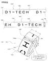
本実施形態の比較例を図7(a)及び図7(b)に示す。上記実施形態と同等の部分には同一の符号を付す。前述したように、搬送ローラ12により搬送される被印字テープ150の被印字層154に対して印字ヘッド11により第1画像155が形成され、さらに剥離材層151が引き剥がされることで印字済みテープ150″が生成される。この比較例では、図7(a)に示すように、この印字済みテープ150″に、上記第1画像155として「D1−TECH」の文字が繰り返して形成されている。
<Comparative example>
A comparative example of the present embodiment is shown in FIGS. 7 (a) and 7 (b). Parts equivalent to those in the above embodiment are denoted by the same reference numerals. As described above, the
そして、印字済みテープ150″が上述したように第3収納部4内の巻取機構40の外周側に巻回され、カッター機構30が印字済みテープ150″を切断することで、第2ロールR2を第3収納部4から取り出し可能となる。このように印字済みテープ150″がロール状に巻回され第2ロールR2となったあとは、図7(b)に示すように、繰り返し印字された上記第1画像155の内容(すなわち「D1−TECH」の文字)の全てを一度に見るのが困難な場合がある。この場合、ユーザは第1画像155の全文字「D1−TECH]の内容の確認がしづらくなる。特に、例えば「D1−TECH」のうちの一部の文字が最外周の印字済みテープ150″に覆われその内側に隠れる場合(図7(b)に示す例では「D」「1」の文字が上記最外周の「C」「H」の文字の径方向内側に隠れている)には、ユーザは、上記第1画像155の内容をすべて見ることはできない。なお、符号P2は、巻芯41に対する、印字済みテープ150″の巻回終端部(搬送方向後方側端部)を表している。
Then, the printed
<第1実施形態の手法の概要>
そこで、第1実施形態においては、図8(a)及び図8(b)に示すように、上記被印字テープ150に対し印字形成が行われて印字済みテープ150″が生成される際、上記第1画像155と共に、当該第1画像155の縮小版である第2画像162が併せて被印字層154に形成される。上述したように、第1画像155は、例えばユーザが被印字テープ150に印字形成したい本来の印字内容(この例では「D1−TECH」の文字)であり、上記イメージバッファ213aに記憶されたドットパターンデータに対応した1つのイメージデータに基づく画像である。一方、第2画像162は、上記第1画像155(「D1−TECH」の文字)を、例えば縦横比が同じ所定倍率で縮小した画像である。この第2画像162に対応する画像データは、上記第1画像155に対応する画像データ(単位印字データに相当)がテープ印刷装置1内部で生成されるときに、併せてテープ印刷装置1内部で生成される。
<Outline of the method of the first embodiment>
Therefore, in the first embodiment, as shown in FIGS. 8A and 8B, when the print-formed
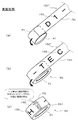
具体的には、上述したように、印字済みテープ150″では、上記「D1−TECH」の文字の第1画像155が、搬送方向(長さ方向)に繰り返して印字形成される(上記図8(a)及び図8(b)参照)。このときに、この例では、印字済みテープ150″に対するカッター機構30による切断部位である、搬送方向後方側端部(言い換えれば巻回時の巻き終わり側終端部)P2の被印字層154の近傍に、上記第2画像162が形成される(図8(c)参照)。この結果、上記第2ロールR2の形成のために巻芯41に印字済みテープ150″が巻回されていくときに(図9(a)及び図(b)参照)、上記巻き終わり側終端部P2の近傍に上記第2画像162が位置することとなる(図9(c)及び上記図8(c)参照)。
Specifically, as described above, on the printed
また、この例では、上記第2画像162は、上記第1画像155と同一内容の縮小版(すなわち「D1−TECH」の文字の縮小版)を、画像長手方向が被印字テープ150の幅方向となるようにして形成されている。これにより、ユーザは、第2ロールR2から印字済みテープ150″を引き剥がして繰り出さなくても、当該第2画像162を見てロール中の第1画像155の印字内容を確認することができる(図8(c)及び図9(c)参照)。
In this example, the
また、図8(c)に示すように、第2画像162には、印字済みテープ150″の幅方向縁部を表現する、矩形枠162aが含まれている。このとき、矩形枠162aの、長手方向に対して直角な幅d(印字済みテープ150″の長さ方向に沿った幅)は、印字済みテープ150″の幅Dに対応している(例えば幅Dを上記所定倍率で割った値となっている)。これにより、ユーザは、第2画像162が、上記第1画像155を縦横比を維持しながら上記所定倍率で縮小した画像であることを、確実に認識することができる。
Further, as shown in FIG. 8C, the
<印刷処理制御内容>
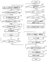
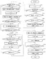
上記の手法を実現するために、テープ印刷装置1のCPU212によって実行される印刷処理の制御内容を、図10のフロー及び図11〜図13により説明する。図10において、例えばユーザによりテープ印刷装置1の電源がオンにされることによって、このフローが開始される(「START」位置)。
<Print processing control details>
The control contents of the printing process executed by the
まず、ステップS202で、CPU212は、操作部216での(又は上記PC217での)ユーザの上記印刷物の作成開始操作に対応した、作成開始指示信号が入力されたか否かを判定する。上記作成開始指示信号が入力されない場合はステップS202の判定が満たされず(S202:NO)、ループ待機する。上記作成開始指示信号が入力されたらステップS202の判定が満たされ(S202:YES)、ステップS203に移る。
First, in step S <b> 202, the
ステップS203では、CPU212は、操作部216での(又は上記PC212での)ユーザの操作に対応して、作成する上記印刷物のテープ長さ(言い換えれば、生成する上記印字済みテープ150″の搬送方向に沿った全長)を表す全長データが入力されたか否かを判定する。ユーザの意図する長さに対応した上記全長データが入力されない場合はステップS203の判定が満たされず(S203:NO)上記ステップS202に戻って同様の手順を繰り返す。上記全長データが入力されたらステップS203の判定が満たされ(S203:YES)、ステップS204に移る。
In step S <b> 203, the
ステップS204では、CPU212は、操作部216での(又は上記PC212での)ユーザの操作に対応して、上記被印字テープ150の上記被印字層154にテープ長さ方向に繰り返して印字形成する、ユーザの所望する1つのイメージを表す印字データ(前述の例では第1画像155に対応したテキストデータ「D1−TECH」)が入力されたか否かを判定する。印字データが入力されない場合はステップS204の判定が満たされず(S204:NO)上記ステップS202に戻って同様の手順を繰り返す。上記印字データが入力されたらステップS204の判定が満たされ(S204:YES)、ステップS205に移る。
In step S <b> 204, the
ステップS205で、CPU212は、上記ステップS204で入力された印字データに対応した、第1画像155の画像データ(上記の例では「D1−TECH」の文字画像データ)を生成する。
In step S205, the
その後、ステップS207で、CPU212は、上記ステップS205で生成された第1画像155を例えば縦横比が同じ倍率で縮小した、第2画像162の画像データ(上記の例では、縮小サイズの「D1−TECH」の文字画像データ)を生成する。
Thereafter, in step S207, the
そして、前述のように、(ユーザが剥離材層151を引き剥がして基材層153及び粘着剤層152からなるテープの先端を巻芯41に取り付けた状態で)、ステップS209で、CPU212は、各モータ駆動回路218,219,220に制御信号を出力し、搬送用モータM1、粘着巻取用モータM2、及び剥離紙巻取用モータM3の駆動を開始して、上記被印字テープ150、印字済みテープ150′、及び印字済みテープ150″の搬送を開始する(図11参照)。
Then, as described above (with the user peeling off the
その後、ステップS210で、CPU212は、上記ステップS204で入力した上記印字データに基づき、公知の手法により、対応する第1画像形成開始位置まで前述の搬送が到達したか(言い換えれば印字ヘッド11が上記第1画像形成開始位置に対向する状態まで、上記テープ搬送が行われたか)否かを判定する。第1画像形成開始位置に到達していない場合、判定は満たされず(S210:NO)、この判定が満たされるまでループ待機する。第1画像形成開始位置に到達した場合、判定は満たされ(S210:YES)、ステップS215に移る。
Thereafter, in step S210, the
ステップS215では、CPU212は、印字ヘッド制御回路221に制御信号を出力し、印字ヘッド11の発熱素子に通電を行って上記被印字テープ150への第1画像155(前述の例では「D1−TECH」の文字)の繰り返し形成を開始する(図12参照)。
In
その後、ステップS220で、CPU212は、上記ステップS204で入力した印字データに基づき、公知の手法により、上記第1画像155の第1画像形成終了位置まで前述の搬送が到達したか(言い換えれば印字ヘッド11が上記第1画像形成終了位置に対向する状態まで、上記テープ搬送が行われたか)否かを判定する。第1画像形成終了位置に到達していない場合、判定は満たされず(S220:NO)、ステップS215に戻り同様の手順を繰り返す。これにより、上述の第1画像155(「D1−TECH」の文字)の形成が続行される(図12参照)。一方、第1画像形成終了位置に到達した場合、判定は満たされ(S220:YES)、ステップS225に移る。
Thereafter, in step S220, the
ステップS225では、上記ステップS204で入力された印字データに基づき決定される上記巻き終わり側終端部P2の位置に対応させて、公知の手法により、上記第2画像162(上記の例では縮小された「D1−TECH」の文字)の形成位置まで前述の搬送が到達したか(言い換えれば印字ヘッド11が上記第2画像形成開始位置に対向する状態まで、上記テープ搬送が行われたか)否かを判定する。第2画像162の形成位置に到達していない場合、判定は満たされず(S225:NO)、この判定が満たされるまでループ待機する。第2画像162の形成位置に到達した場合、判定は満たされ(S225:YES)、ステップS230に移る。
In step S225, the second image 162 (reduced in the above example is reduced in accordance with the position of the winding end side end portion P2 determined based on the print data input in step S204 by a known method. Whether or not the above-described conveyance has reached the formation position of “D1-TECH” (in other words, whether or not the tape conveyance has been performed until the
ステップS230では、CPU212は、印字ヘッド制御回路221に制御信号を出力し、印字ヘッド11の発熱素子に通電を行って上記被印字テープ150に対し、第2画像162(前述の例では縮小された「D1−TECH」の文字)を形成する(図13参照)。この第2画像162には、前述したように矩形枠162aが含まれる(上記図9参照)。その後、ステップS245に移る。
In step S230, the
ステップS245では、CPU212は、印字ヘッド制御回路221に制御信号を出力し、印字ヘッド11の発熱素子への通電を停止して、上記被印字テープ150に対するすべての印字形成を停止する。その後、ステップS250に移る。
In step S 245, the
ステップS250では、上記巻き終わり側終端部P2の位置(言い替えればその後続の印字済みテープ150″のための上記巻き始め側始端部P1の位置。上記図9(a)も参照)が、上記カッター機構30の位置(詳細には上記可動刃の位置)となるまで前述の搬送が到達したか否かを判定する(図14参照)。カッター機構30の位置に到達していない場合、判定は満たされず(S250:NO)、この判定が満たされるまでループ待機する。搬送がカッター機構30の位置に到達した場合、判定は満たされ(S250:YES)、ステップS255に移る。
In step S250, the position of the winding end side end portion P2 (in other words, the position of the winding start side start end portion P1 for the subsequent printed
ステップS255では、CPU212は、各モータ駆動回路218,219,220に制御信号を出力し、搬送用モータM1、粘着巻取用モータM2、及び剥離紙巻取用モータM3の駆動を停止する。これにより、上記被印字テープ150、印字済みテープ150′、及び印字済みテープ150″の上記第2画像162形成位置よりも上流側にある中間部P(切断後は巻き終わり側終端部P2及び巻き始め側始端部P1となる位置)が上記カッター機構30の位置となった状態で、搬送が停止する(図14参照)。
In step S255, the
その後、ステップS260で、CPU212は、カッターモータMCのモータ駆動回路222に制御信号を出力し、カッターモータMCを駆動してカッター機構30の作動による印字済みテープ150″の上記中間部Pの切断を行う。この切断後には、先行する搬送方向下流側の印字済みテープ150′の切断端部が上記巻き終わり側終端部P2となり、後続する搬送方向上流側の印字済みテープ150″の切断端部が上記巻き始め側始端部P1となる(図15参照)。
Thereafter, in step S260, the
そして、ステップS265に移り、モータ駆動回路219に制御信号を出力し、粘着巻取用モータM2の駆動を開始して、上記切断端部(巻き終わり側終端部P2)より下流側のすべての印字済みテープ150′を巻芯41へと巻き取る。
Then, the process proceeds to step S265, where a control signal is output to the
その後、ステップS270で、CPU212は、上記ステップS260でのカッター機構30の切断動作から所定時間だけ経過したか否かを判定する。所定時間だけ経過していない場合、判定は満たされず(S270:NO)、この判定が満たされるまでループ待機する。この所定時間は、上記巻き終わり側終端部P2よりも搬送方向下流側のすべての印字済みテープ150″を巻芯41へと巻き取れるだけの時間でよい。所定時間が経過したらこの判定は満たされ(S270:YES)、ステップS275へ移る。
Thereafter, in step S270, the
ステップS275では、CPU212は、モータ駆動回路219に制御信号を出力し、粘着巻取用モータM2の駆動を停止する。これにより、上記切断により生じた上記巻き終わり側終端部P2よりも搬送方向下流側のすべての印字済みテープ150″を確実に第2ロールR2で巻き取ることができる。この結果、巻芯41の外周側に巻回された第2ロールR2側の印字済みテープ150″(上記巻き終わり側終端部P2の近傍に第2画像162を備える)と、被印字テープ150に連結された状態の後続の印字済みテープ150″とが、分断されて離間した状態となる(図15参照)。
In step S275, the
その後、ステップS280で、CPU212は、上記の処理がすべて正常に行われ終了した旨を上記表示部215(又はPC217)に表示するなどにより報知する。そして、このフローを終了する。
Thereafter, in step S280, the
なお、上記ステップS204が各請求項記載のデータ取得手順に相当し、そのステップS204の処理を実行するCPU212が、各請求項記載のデータ取得手段として機能する。また、上記ステップS205〜ステップS280が各請求項記載の連携制御手順に相当し、それら各ステップの処理を実行するCPU212が、各請求項記載の連携制御手段として機能する。
Note that step S204 corresponds to the data acquisition procedure described in each claim, and the
なお、上記した図10のフローを実行するテープ印刷プログラムは、事前に上記テープ印刷装置1のROM214に記憶させるのではなく、適宜の記録媒体に記録しておいても良い。この場合、当該記録媒体に対し適宜のタイミングで読み取りが行われて当該テープ印刷プログラムが取得され、その取得後にテープ印刷装置1のCPU212が当該プログラムを実行する。
Note that the tape printing program for executing the above-described flow of FIG. 10 may be recorded in an appropriate recording medium instead of being stored in advance in the
<第1実施形態による効果>
以上説明したように、本実施形態においては、上記のようにして印字形成が行われた後の印字済みテープ150″には、ユーザが意図する第1画像155(上記の例では「D1−TECH」の文字)に加え、その縮小版画像である第2画像162も形成されている。これにより、ユーザは、上記印字済みテープ150″に形成された上記第1画像155を長さ方向全長にわたって見なくても、上記第2画像162を見るだけで、当該第1画像155の内容を容易に確認することができる。この結果、ユーザの利便性を向上することができる。このとき、上記第2ロールR2のように、印字済みテープ150″がロール状に巻回されている場合には、当該ロール中において巻回された状態では特に上記第1画像155の確認がしづらいので、第2ロールR2中の巻き終わり側終端部P2に第2画像162が存在することによる、容易な視認性が特に効果的である。
<Effects of First Embodiment>
As described above, in the present embodiment, the
また、本実施形態では、特に、第1画像155は画像長手方向をテープ長さ方向として形成される一方、第2画像162は画像長手方向をテープ幅方向として形成される(図8(b)、図8(c)、図9(c)参照)。これにより、第1画像155の長さがテープ長さ方向に沿って比較的長い場合であっても、その縮小版である第2画像162については、テープ幅方向に沿ってコンパクトにまとめ、テープ幅以内に配置することができる。
In the present embodiment, in particular, the
また、本実施形態では特に、第2画像162内において、印字済みテープ150″の幅方向縁部を表す矩形枠162aが、第2画像162の一部として描画される(図8(b)、図8(c)、図9(c)参照)。これにより、本来の印字内容である第1画像155とテープ幅との関係が一目瞭然となる。この結果、さらにユーザの利便性を向上することができる。
In the present embodiment, in particular, in the
また、本実施形態では特に、印字済みテープ150″において、上記単位印字データに対応した第1画像155が長さ方向(搬送方向)に繰り返して印字形成される(図8(a)及び図8(b)等参照)。これにより、このように繰り返して形成される第1画像155の内容を、その縮小版である第2画像162によってユーザが容易に確認することができる。
In the present embodiment, in particular, on the printed
なお、以上においては、テープ印刷装置1に有線あるいは無線による通信回線を介してPC217(外部の操作端末)が接続されている。しかしながら、本発明はこれに限定されるものではなく、上記テープ印刷装置1を、PC217と同等の機能を果たす構成を組み込んだ、いわゆるスタンドアローンタイプのテープ印刷装置1としても良い。このスタンドアローンタイプのテープ印刷装置1においても、上記した本実施形態と同様の作用効果を有する。
In the above description, the PC 217 (external operation terminal) is connected to the
また、上記第1実施形態は、上記の態様に限られるものではなく、その趣旨及び技術的思想を逸脱しない範囲内で種々の変形が可能である。以下、そのような条件を満たす各種変形例を順を追って説明する。なお、上記第1実施形態と同等の部分には同一の符号を付し、適宜説明を省略又は簡略化する。 The first embodiment is not limited to the above-described aspect, and various modifications can be made without departing from the spirit and technical idea of the first embodiment. Hereinafter, various modifications satisfying such conditions will be described in order. In addition, the same code | symbol is attached | subjected to the part equivalent to the said 1st Embodiment, and description is abbreviate | omitted or simplified suitably.
(1)第2画像の形成の必要有無を判定する場合
本変形例では、印字形成される上記第1画像155の搬送方向長さが、第2ロールR2のロール最外周の周長(すなわちロール最外周に巻回される印字済みテープ150″の1周分の長さ)以下であるか否かが判定される。
(1) When Determining Necessity of Forming Second Image In this modification, the length of the
例えば、図16(a)に示すように、文字「ABC」の第1画像155が印字済みテープ150″に形成されている場合、その搬送方向長さは(3文字分しかないことから)比較的短くなる。したがって第2ロールR2に巻回された状態でも、図16(b)に示すように、ユーザが手元で適宜に第2ロールR2を回転させることで、ロールのどこかに形成された文字「ABC」を容易に視認することができる。特に、上記第1画像155の長さが上記ロール周長以下である場合には、巻芯41への巻回時において、上記図7(b)や図9(c)に示したように第1画像155のうち先行して巻回された部分が後から巻回される部分によって径方向外周側から覆われることはない。したがって、縮小された文字「ABC」の第2画像162を形成する必要性に乏しい。
For example, as shown in FIG. 16A, when the
これに対して、上記第1画像155の長さが上記ロール周長よりも長い場合、巻芯41への巻回が進むにつれて、第1画像155のうち先行して巻回された部分は後から巻回される部分によって径方向外周側から覆われた状態となる(図7(b)や図9(c)参照)。その結果、第2ロールR2が形成された後に第1画像155の全てがロール表面に露出することはなく、第1画像155の全ての内容を視認することは不可能となる。
On the other hand, when the length of the
そこで、本変形例では、上述の第1画像155の長さがロール周長より長い場合にのみ、上記縮小された第2画像162の形成が行われる。
Therefore, in the present modification, the reduced
図17は、本変形例におけるテープ印刷装置1のCPU212によって実行される印刷処理の制御内容を示すフローチャートである。
FIG. 17 is a flowchart showing the control contents of the printing process executed by the
図17では、上記第1実施形態の図10に示すフローにおいて、ステップS202の前にステップS201が、ステップS205の後にステップS206が、ステップS207の後にステップS208が、ステップS220の後にステップS223が、それぞれ新たに設けられている。 In FIG. 17, in the flow shown in FIG. 10 of the first embodiment, step S201 before step S202, step S206 after step S205, step S208 after step S207, step S223 after step S220, Each is newly provided.
すなわち、図17において、ステップS201では、CPU212は、第2画像形成フラグFをF=0に初期化する。
That is, in FIG. 17, in step S201, the
その後、上記図10と同様のステップS202〜ステップS205を経て、ステップS206に移る。ステップS206では、CPU212は、上記ステップS203で入力された全長データと、ステップS204で入力した印字データと、を参照しつつ、上記ステップS205で生成された第1画像155の画像データに基づき、当該第1画像155の長さ(前述の例では文字「ABC」や文字「D1−TEC」の印刷長さ)が、上記周長以下であるか否かを判定する。1周分の長さ以下でない場合、判定は満たされず(S206:NO)、上記同様のステップS207に移行した後、ステップS208で、CPU212は上記第2画像形成フラグFをF=1に設定する。その後、ステップS209に移る。一方、第1画像155の長さが上記周長以下である場合は、ステップS206の判定が満たされ(S206:YES)、ステップS209に移る。
Thereafter, the process proceeds to step S206 through steps S202 to S205 similar to those in FIG. In step S206, the
その後のステップS209〜ステップS220は上記同様であり、説明を省略する。ステップS220の後、新たに設けたステップS223では、CPU212は、上記第2画像形成フラグFがF=1であるか否かを判定する。F=1であった場合は、ステップS223の判定は満たされ(S223:YES)、上記第1画像155が長く第2画像162の形成の必要があるとみなされて、ステップS225に移る。その後、上記同様のステップS225、ステップS230を経て、ステップS245に移る。一方、ステップS223においてF=0であった場合、判定は満たされず(S223:NO)、上記第1画像155が短く第2画像162の形成の必要がないとみなされてステップS245に移行する。
Subsequent steps S209 to S220 are the same as described above, and a description thereof will be omitted. In step S223 newly provided after step S220, the
ステップS245以降は、上記した図10と同様であるので、説明を省略する。 Step S245 and subsequent steps are the same as those in FIG.
なお、本変形例において、上記ステップS206を実行するCPU212が各請求項記載の長さ判定手段として機能する。また、上記ステップS206を除いて、ステップS205〜ステップS280の各手順が本変形例における各請求項記載の連携制御手順に相当し、それらを実行するCPU212が連携制御手段として機能する。
In this modification, the
上記したように、本変形例においても、上記した第1実施形態と同様の効果を得る。また、本変形例においては特に、第1画像155の長さがロール最外周における印字済みテープ150″の1周分の長さより長い場合にのみ、第2画像162の形成が行われる。これにより、必要性が低い場合に第2画像162が無駄に形成されるのを回避し、被印字テープ150の浪費を防止することができる。
As described above, also in this modification, the same effect as that of the first embodiment described above is obtained. In the present modification, in particular, the
(2)第2画像の形成態様のバリエーション
第2画像162の形成態様は、上記第1実施形態のように、印字済みテープ150″のうち巻き終わり側終端部P2の1カ所に形成するのには限られない。例えば、図18(a)及び図18(b)に示すように、第1画像155(「D1−TECH」の文字)が繰り返し印字形成されるときの、各第1画像155が形成されるごとに、毎回、第2画像162を形成(言い換えれば隣接する2つの第1画像155,155の間すべてにそれぞれ形成)してもよい。また、図19に示すように、印字済みテープ150″のうち、第1画像155(「D1−TECH」の文字)が長さ方向全長にわたって繰り返し印字形成される印字済みテープ150″において、途中一箇所にだけ上記第2画像162を形成してもよい。
(2) Variation of Forming Form of Second Image The
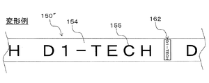
さらには、図18(a)及び図18(b)にそれぞれ対応する図20(a)及び図20(b)に示すように、第2画像162を、その画像長手方向を印字済みテープ150″の長手方向(搬送方向)として形成してもよい。この場合、印字済みテープ150″における隣接する2つの第1画像155,155の相互間に、当該第1画像155と同じ向きとなるように、縮小された第2画像162が形成される。さらには、図19に対応する図21に示すように、印字済みテープ150″のうち、印字済みテープ150″の途中一箇所にだけ、上記第2画像162を形成してもよい。これらの場合も、上記第1実施形態と同様の作用効果を有する。
Further, as shown in FIGS. 20 (a) and 20 (b) corresponding to FIGS. 18 (a) and 18 (b), the
<第2実施形態>
本発明の第2実施形態を図22及び図23により説明する。この実施形態では、前述したように、シュート15の切替操作でテープ経路が切り替えられることで、印字形成後の印字済みテープ150″(又は非粘着テープでもよい。以下同様)は、筐体2に設けた排出口(図示省略)から筐体2外部へ排出される。この場合、上述したように、印字済みテープ150″は、第3収納部4内において第2ロールR2へと巻回されることなく、テープ状のままで排出される。
Second Embodiment
A second embodiment of the present invention will be described with reference to FIGS. In this embodiment, as described above, the tape path is switched by the switching operation of the
このとき排出される印字済みテープ150″には、図22(a)及び図22(b)に示すように、第1画像155(「D1−TECH」の文字)が形成され、その端部には、第1画像155(「D1−TECH」の文字)と同一内容の縮小版である上記第2画像162が形成される。なお、図示の例では、説明の明確化のために、印字済みテープ150″に第1画像155(「D1−TECH」の文字)が1つだけ備えられる場合(印字済みテープ150″が比較的短い場合)を例に取っているが、複数個の第1画像155(「D1−TECH」の文字)が備えられていてもよい。
On the printed
本実施形態における作用効果を、比較例を用いつつ説明する。本実施形態の比較例を図23(a)に示す。この比較例では、上記図22(a)及び図22(b)に示すのと異なり、上記印字済みテープ150″に第2画像162が設けられない。この場合、上記のように筐体2の外部に排出された後の印字済みテープ150″では、例えば第1ロールR1に巻回されていたときの曲がり癖が残っている結果、図23(a)に示すように、見る角度によって陰になる部分が生じる。したがって、上記第1画像155(「D1−TECH」の文字)の全体像が見えづらい状態があり得る(符号Eで示すユーザの視線位置を参照)。特に、印字済みテープ150″に形成された上記第1画像155の長さ(印刷長さ)がテープ長さ方向に沿って比較的長い場合には、第1画像155の内容を確認するためには、印字済みテープ150″をユーザが手元で長く伸ばし広げた状態とする必要がある。
The effect in this embodiment is demonstrated using a comparative example. A comparative example of this embodiment is shown in FIG. In this comparative example, unlike the case shown in FIGS. 22A and 22B, the
これに対し、本実施形態では、図22(a)及び図22(b)に示すように、印字済みテープ150″に、上記第1画像155に加え、その縮小版画像である第2画像162が形成されている。これにより、図23(b)に示すように、ユーザは、上記のような伸ばし広げ操作を行って印字済みテープ150″に形成された上記第1画像155を長さ方向全長にわたって見なくても、上記第2画像162の部分を見るだけで、当該第1画像155の内容を確認することができる。この結果、ユーザの利便性を向上することができる。
On the other hand, in this embodiment, as shown in FIGS. 22A and 22B, in addition to the
また、上記のような曲がり癖がなくても、例えば印字済みテープ150″に形成された上記第1画像155の印刷長さがテープ長さ方向に沿ってかなり長い場合には、当該第1画像155の内容を確認するためには、ユーザが印字済みテープ150″との距離を大きく取って印字済みテープ150″全体を遠くから眺める必要があり、面倒である。これに対して、本実施形態では、特に、印字済みテープ150″に局所的に形成された上記第2画像162を見ることで上記第1画像155の内容を確認できるので、上記のようにユーザが印字済みテープ150″との距離をわざわざ大きく取る必要もない。この意味でもユーザの利便性を向上することができる。
Further, even if there is no bend as described above, for example, when the printing length of the
<その他>
なお、以上は、被印字テープ150に上記第1画像155を形成するテープ印刷装置1に対し本発明を適用した場合を例にとって説明したが、これに限られない。すなわち、ラベル作成用の被印字テープ(例えばテープ基材層と粘着層とを備える)に所望の印刷を行って印字ラベルを作成する印字ラベル作成装置に対し、本発明を適用してもよい。この場合も同様の効果を得る。
<Others>
In the above description, the case where the present invention is applied to the
また、以上の説明において、「垂直」「平行」「平面」等の記載がある場合には、当該記載は厳密な意味ではない。すなわち、それら「垂直」「平行」「平面」とは、設計上、製造上の公差、誤差が許容され、「実質的に垂直」「実質的に平行」「実質的に平面」という意味である。 In addition, in the above description, when there are descriptions such as “vertical”, “parallel”, and “plane”, the descriptions are not strict. That is, the terms “vertical”, “parallel”, and “plane” are acceptable in design and manufacturing tolerances and errors, and mean “substantially vertical”, “substantially parallel”, and “substantially plane”. .
また、以上の説明において、外観上の寸法や大きさが「同一」「等しい」「異なる」等の記載がある場合は、当該記載は厳密な意味ではない。すなわち、それら「同一」「等しい」「異なる」とは、設計上、製造上の公差、誤差が許容され、「実質的に同一」「実質的に等しい」「実質的に異なる」という意味である。 In addition, in the above description, when there are descriptions such as “same”, “equal”, “different”, etc., in terms of external dimensions and sizes, the descriptions are not strict. That is, the terms “identical”, “equal”, and “different” mean that “tolerance and error in manufacturing are allowed in design and that they are“ substantially identical ”,“ substantially equal ”, and“ substantially different ”. .
なお、以上において、図6に示す矢印は信号の流れの一例を示すものであり、信号の流れ方向を限定するものではない。 In the above, the arrows shown in FIG. 6 show an example of the signal flow, and do not limit the signal flow direction.
また、上記図10及び図17に示したフローチャートは本発明を上記フローに示す手順に限定するものではなく、発明の趣旨及び技術的思想を逸脱しない範囲内で手順の追加・削除又は順番の変更等をしてもよい。 Further, the flowcharts shown in FIGS. 10 and 17 do not limit the present invention to the procedure shown in the above-described flow, and the addition / deletion of the procedure or the change of the order within the scope not departing from the gist and technical idea of the invention. Etc. may be used.
また、以上既に述べた以外にも、上記実施形態や各変形例による手法を適宜組み合わせて利用してもよい。 In addition to those already described above, the methods according to the above-described embodiments and modifications may be used in appropriate combination.
その他、一々例示はしないが、本発明は、その趣旨を逸脱しない範囲内において、種々の変更が加えられて実施されるものである。 In addition, although not illustrated one by one, the present invention is implemented with various modifications within a range not departing from the gist thereof.
1 テープ印刷装置
11 印字ヘッド
12 搬送ローラ(搬送手段)
41 巻芯(巻芯部材)
150 被印字テープ
150′ 印字済みテープ
150″ 印字済みテープ
152 粘着剤層
153 基材層
154 被印字層
155 第1画像
162 第2画像
162a 幅方向縁部を表す画像部分
212 CPU(演算手段)
P1 巻き始め側始端部
P2 巻回終端部
M1 搬送用モータ(搬送用駆動手段)
M2 巻取用モータ(巻取用駆動手段)
R1 第1ロール(被印字テープロール)
R2 第2ロール(印字済みテープロール)
DESCRIPTION OF
41 Core (core member)
DESCRIPTION OF
P1 Winding start side start end P2 Winding end point M1 Conveyance motor (conveyance drive means)
M2 Winding motor (winding drive means)
R1 first roll (printed tape roll)
R2 2nd roll (printed tape roll)
Claims (8)
前記搬送手段を回転駆動する駆動力を発生する搬送用駆動手段と、
前記搬送手段により搬送される前記被印字テープに対し、印字を形成する印字手段と、
前記印字手段による印字形成のための印字データを取得するデータ取得手段と、
前記データ取得手段により取得された前記印字データに対応した第1画像、及び、前記第1画像を縮小した第2画像、を共に前記被印字テープに印字形成するように、前記搬送用駆動手段及び前記印字手段を連携して制御する連携制御手段と、
を有することを特徴とするテープ印刷装置。 A conveying means for feeding and conveying the print-receiving tape from the print-receiving tape roll;
A drive means for transport for generating a driving force for rotationally driving the transport means;
Printing means for forming a print on the print-receiving tape conveyed by the conveying means;
Data acquisition means for acquiring print data for print formation by the printing means;
The transport driving means and the transport driving means so as to print and form both the first image corresponding to the print data obtained by the data obtaining means and the second image obtained by reducing the first image on the print-receiving tape. Cooperation control means for controlling the printing means in cooperation;
A tape printer characterized by comprising:
前記連携制御手段は、
画像長手方向を前記被印字テープの長さ方向として前記第1画像を形成し、画像長手方向を前記被印字テープの幅方向として前記第2画像を形成するように、前記搬送用駆動手段及び前記印字手段を制御する
ことを特徴とするテープ印刷装置。 The tape printer according to claim 1, wherein
The cooperation control means includes
The transport driving means and the transporting means, and the first image is formed with the image longitudinal direction as the length direction of the print-receiving tape, and the second image is formed with the image longitudinal direction as the width direction of the print-receiving tape. A tape printer which controls printing means.
前記連携制御手段は、
前記被印字テープの幅方向縁部を表す画像部分を含む前記第2画像を形成するように、前記搬送用駆動手段及び前記印字手段を制御する
ことを特徴とするテープ印刷装置。 In the tape printer according to claim 1 or 2,
The cooperation control means includes
The tape printing apparatus, wherein the transport driving unit and the printing unit are controlled so as to form the second image including an image portion representing a width direction edge of the print-receiving tape.
前記データ取得手段は、
前記印字データとして、繰り返し印字用の1つの単位印字データを取得し、
前記連携制御手段は、
前記単位印字データに対応した前記第1画像を、前記被印字テープにおいて搬送方向に沿って複数個繰り返して形成し、かつ、前記第2画像を、前記被印字テープにおいて少なくとも1つ形成するように、前記搬送用駆動手段及び前記印字手段を制御する
ことを特徴とするテープ印刷装置。 The tape printer according to any one of claims 1 to 3,
The data acquisition means includes
As the print data, one unit print data for repeated printing is acquired,
The cooperation control means includes
A plurality of the first images corresponding to the unit print data are repeatedly formed along the transport direction on the print-receiving tape, and at least one second image is formed on the print-receiving tape. A tape printer which controls the drive means for conveyance and the printing means.
前記印字手段により前記第1画像及び前記第2画像が形成された印字済みテープを、前記第1画像及び前記第2画像を外周側としつつ巻芯部材の外周部に順次巻回し、印字済みテープロールを形成する巻取手段と、
前記巻取手段を回転駆動する駆動力を発生する巻取用駆動手段と、
を有し、
前記連携制御手段は、
前記巻取手段により巻回される前記印字済みテープの搬送方向後方側端部の近傍に前記第2画像が形成されるように、前記搬送用駆動手段、前記印字手段、及び、前記巻取用駆動手段を連携して制御する
ことを特徴とするテープ印刷装置。 The tape printer according to any one of claims 1 to 4,
The printed tape on which the first image and the second image are formed by the printing unit is sequentially wound around the outer peripheral portion of the core member with the first image and the second image as the outer peripheral side. Winding means for forming a roll;
Winding drive means for generating a driving force for rotationally driving the winding means;
Have
The cooperation control means includes
The transport driving unit, the printing unit, and the winding unit are formed so that the second image is formed in the vicinity of the rear end portion in the transport direction of the printed tape wound by the winding unit. A tape printer which controls driving means in cooperation.
前記被印字テープに印字形成される前記第1画像の搬送方向長さが、前記印字済みテープロールのロール最外周に巻回される前記印字済みテープの1周分の長さ以下であるか否かを判定する長さ判定手段を有し、
前記連携制御手段は、
前記長さ判定手段により前記第1画像の前記搬送方向長さが前記印字済みテープの前記1周分の長さ以下であると判定された場合には前記第2画像の印字形成を行わずに前記第1画像の印字形成を行い、前記長さ判定手段により前記第1画像の前記搬送方向長さが前記印字済みテープの前記1周分の長さより大きいと判定された場合には、前記第1画像及び前記第2画像の印字形成を行うように、前記搬送用駆動手段、前記印字手段、及び前記巻取用駆動手段を連携して制御する
ことを特徴とするテープ印刷装置。 The tape printer according to claim 5, wherein
Whether or not the length of the first image printed on the print-receiving tape in the transport direction is equal to or shorter than the length of one round of the printed tape wound around the outermost roll of the printed tape roll Having a length judging means for judging
The cooperation control means includes
If the length determination unit determines that the length of the first image in the transport direction is equal to or less than the length of the one round of the printed tape, the second image is not printed. When printing of the first image is performed and the length determination unit determines that the length of the first image in the transport direction is greater than the length of the printed tape, the first image A tape printing apparatus, wherein the transport driving unit, the printing unit, and the winding driving unit are controlled in cooperation so as to perform printing formation of one image and the second image.
前記巻芯部材に巻回された前記印字済みテープは、
巻回時の巻き終わり側端部の近傍の前記被印字層に、前記第1画像を縮小した第2画像が印字形成されている
ことを特徴とする印字済みテープロール。 A printed tape comprising: a base material layer; and a print-receiving layer provided on one side in the thickness direction of the base material layer and on which a predetermined first image is repeatedly printed along the length direction. A printed tape roll configured by sequentially winding around the core member with the printed layer as the outer peripheral side,
The printed tape wound around the core member is:
A printed tape roll, wherein a second image obtained by reducing the first image is printed on the print-receiving layer in the vicinity of an end portion on the winding end side during winding.
前記印字手段による印字形成のための印字データを取得するデータ取得手順と、
前記データ取得手順で取得された前記印字データに対応した第1画像、及び、前記第1画像を縮小した第2画像、を共に前記被印字テープに印字形成するように、前記搬送用駆動手段及び前記印字手段を連携して制御する連携制御手順と、
を実行させるための、テープ印刷プログラム。 Conveying means for conveying the print-receiving tape; conveying drive means for generating a driving force for rotationally driving the conveying means; and printing means for forming a print on the print-receiving tape conveyed by the conveying means; For the arithmetic means provided in the tape printer having
A data acquisition procedure for acquiring print data for print formation by the printing means;
The transport driving means, and the first image corresponding to the print data acquired in the data acquisition procedure and the second image obtained by reducing the first image are printed on the print-receiving tape. A cooperative control procedure for controlling the printing means in cooperation;
Tape printing program to execute
Priority Applications (1)
| Application Number | Priority Date | Filing Date | Title |
|---|---|---|---|
| JP2014129664A JP6299972B2 (en) | 2014-06-24 | 2014-06-24 | Tape printing apparatus and tape printing program |
Applications Claiming Priority (1)
| Application Number | Priority Date | Filing Date | Title |
|---|---|---|---|
| JP2014129664A JP6299972B2 (en) | 2014-06-24 | 2014-06-24 | Tape printing apparatus and tape printing program |
Publications (2)
| Publication Number | Publication Date |
|---|---|
| JP2016007772A true JP2016007772A (en) | 2016-01-18 |
| JP6299972B2 JP6299972B2 (en) | 2018-03-28 |
Family
ID=55225697
Family Applications (1)
| Application Number | Title | Priority Date | Filing Date |
|---|---|---|---|
| JP2014129664A Active JP6299972B2 (en) | 2014-06-24 | 2014-06-24 | Tape printing apparatus and tape printing program |
Country Status (1)
| Country | Link |
|---|---|
| JP (1) | JP6299972B2 (en) |
Cited By (1)
| Publication number | Priority date | Publication date | Assignee | Title |
|---|---|---|---|---|
| JP2021070266A (en) * | 2019-10-31 | 2021-05-06 | 株式会社ミマキエンジニアリング | Rolled printing medium and printing apparatus |
Citations (6)
| Publication number | Priority date | Publication date | Assignee | Title |
|---|---|---|---|---|
| JPH09123561A (en) * | 1995-10-31 | 1997-05-13 | Brother Ind Ltd | Printer device |
| JPH11254779A (en) * | 1998-03-10 | 1999-09-21 | Brother Ind Ltd | Printer device and recording medium recording printer control program |
| JP2002121513A (en) * | 2000-10-17 | 2002-04-26 | Miyoshi:Kk | Pressure-sensitive adhesive tape |
| US6380965B1 (en) * | 1994-10-14 | 2002-04-30 | Esselte N.V. | Tape printing apparatus |
| JP2004025583A (en) * | 2002-06-25 | 2004-01-29 | Seiko Epson Corp | Tape printing apparatus and its tape printing method, program, and storage medium |
| JP2013233663A (en) * | 2012-05-02 | 2013-11-21 | Brother Industries Ltd | Adhesive tape printing apparatus |
-
2014
- 2014-06-24 JP JP2014129664A patent/JP6299972B2/en active Active
Patent Citations (6)
| Publication number | Priority date | Publication date | Assignee | Title |
|---|---|---|---|---|
| US6380965B1 (en) * | 1994-10-14 | 2002-04-30 | Esselte N.V. | Tape printing apparatus |
| JPH09123561A (en) * | 1995-10-31 | 1997-05-13 | Brother Ind Ltd | Printer device |
| JPH11254779A (en) * | 1998-03-10 | 1999-09-21 | Brother Ind Ltd | Printer device and recording medium recording printer control program |
| JP2002121513A (en) * | 2000-10-17 | 2002-04-26 | Miyoshi:Kk | Pressure-sensitive adhesive tape |
| JP2004025583A (en) * | 2002-06-25 | 2004-01-29 | Seiko Epson Corp | Tape printing apparatus and its tape printing method, program, and storage medium |
| JP2013233663A (en) * | 2012-05-02 | 2013-11-21 | Brother Industries Ltd | Adhesive tape printing apparatus |
Cited By (2)
| Publication number | Priority date | Publication date | Assignee | Title |
|---|---|---|---|---|
| JP2021070266A (en) * | 2019-10-31 | 2021-05-06 | 株式会社ミマキエンジニアリング | Rolled printing medium and printing apparatus |
| JP7301718B2 (en) | 2019-10-31 | 2023-07-03 | 株式会社ミマキエンジニアリング | Rolled print media and printing device |
Also Published As
| Publication number | Publication date |
|---|---|
| JP6299972B2 (en) | 2018-03-28 |
Similar Documents
| Publication | Publication Date | Title |
|---|---|---|
| JP6132260B2 (en) | Print data editing program | |
| JP6398225B2 (en) | Printing device | |
| JP6331215B2 (en) | Printing device | |
| JP6288492B2 (en) | Tape printer and printed tape roll | |
| JP6323674B2 (en) | Print production device | |
| JP6299972B2 (en) | Tape printing apparatus and tape printing program | |
| JP5854309B2 (en) | Print creation program | |
| WO2015064254A1 (en) | Tape cartridge and printing device | |
| JP5963046B2 (en) | Print medium cartridge, foldable body, and printing apparatus | |
| JP6331487B2 (en) | Printing device | |
| JP6132261B2 (en) | Print production device | |
| JP6281466B2 (en) | Medium cartridge and printing apparatus | |
| JP2016013638A (en) | Printed matter preparation device | |
| JP6323656B2 (en) | Print production device | |
| JP6327504B2 (en) | Print production device | |
| JP6229893B2 (en) | Printing device | |
| JP6358022B2 (en) | RECORDED MEDIUM ROLL AND PRINTING DEVICE | |
| JP6237351B2 (en) | Printing device | |
| JP2015168071A (en) | Printed matter creation device | |
| JP6229890B2 (en) | Printing device | |
| JP6222561B2 (en) | Print production device | |
| JP7382024B2 (en) | printing device | |
| JP2015067792A (en) | Adhesive tape roll | |
| JP5945941B2 (en) | Print medium cartridge | |
| JP2016068492A (en) | Printer |
Legal Events
| Date | Code | Title | Description |
|---|---|---|---|
| A621 | Written request for application examination |
Free format text: JAPANESE INTERMEDIATE CODE: A621 Effective date: 20161209 |
|
| A977 | Report on retrieval |
Free format text: JAPANESE INTERMEDIATE CODE: A971007 Effective date: 20170927 |
|
| A131 | Notification of reasons for refusal |
Free format text: JAPANESE INTERMEDIATE CODE: A131 Effective date: 20171003 |
|
| A521 | Request for written amendment filed |
Free format text: JAPANESE INTERMEDIATE CODE: A523 Effective date: 20171129 |
|
| TRDD | Decision of grant or rejection written | ||
| A01 | Written decision to grant a patent or to grant a registration (utility model) |
Free format text: JAPANESE INTERMEDIATE CODE: A01 Effective date: 20180131 |
|
| A61 | First payment of annual fees (during grant procedure) |
Free format text: JAPANESE INTERMEDIATE CODE: A61 Effective date: 20180213 |
|
| R150 | Certificate of patent or registration of utility model |
Ref document number: 6299972 Country of ref document: JP Free format text: JAPANESE INTERMEDIATE CODE: R150 |