JP2016009121A - 光走査用アクチュエータおよび光走査装置 - Google Patents
光走査用アクチュエータおよび光走査装置 Download PDFInfo
- Publication number
- JP2016009121A JP2016009121A JP2014130350A JP2014130350A JP2016009121A JP 2016009121 A JP2016009121 A JP 2016009121A JP 2014130350 A JP2014130350 A JP 2014130350A JP 2014130350 A JP2014130350 A JP 2014130350A JP 2016009121 A JP2016009121 A JP 2016009121A
- Authority
- JP
- Japan
- Prior art keywords
- optical fiber
- optical
- piezoelectric element
- optical scanning
- actuator
- Prior art date
- Legal status (The legal status is an assumption and is not a legal conclusion. Google has not performed a legal analysis and makes no representation as to the accuracy of the status listed.)
- Granted
Links
Images









Classifications
-
- G—PHYSICS
- G02—OPTICS
- G02B—OPTICAL ELEMENTS, SYSTEMS OR APPARATUS
- G02B26/00—Optical devices or arrangements for the control of light using movable or deformable optical elements
- G02B26/08—Optical devices or arrangements for the control of light using movable or deformable optical elements for controlling the direction of light
- G02B26/10—Scanning systems
- G02B26/103—Scanning systems having movable or deformable optical fibres, light guides or waveguides as scanning elements
-
- A—HUMAN NECESSITIES
- A61—MEDICAL OR VETERINARY SCIENCE; HYGIENE
- A61B—DIAGNOSIS; SURGERY; IDENTIFICATION
- A61B1/00—Instruments for performing medical examinations of the interior of cavities or tubes of the body by visual or photographical inspection, e.g. endoscopes; Illuminating arrangements therefor
- A61B1/00002—Operational features of endoscopes
- A61B1/00004—Operational features of endoscopes characterised by electronic signal processing
- A61B1/00006—Operational features of endoscopes characterised by electronic signal processing of control signals
-
- A—HUMAN NECESSITIES
- A61—MEDICAL OR VETERINARY SCIENCE; HYGIENE
- A61B—DIAGNOSIS; SURGERY; IDENTIFICATION
- A61B1/00—Instruments for performing medical examinations of the interior of cavities or tubes of the body by visual or photographical inspection, e.g. endoscopes; Illuminating arrangements therefor
- A61B1/00163—Optical arrangements
- A61B1/00172—Optical arrangements with means for scanning
-
- A—HUMAN NECESSITIES
- A61—MEDICAL OR VETERINARY SCIENCE; HYGIENE
- A61B—DIAGNOSIS; SURGERY; IDENTIFICATION
- A61B1/00—Instruments for performing medical examinations of the interior of cavities or tubes of the body by visual or photographical inspection, e.g. endoscopes; Illuminating arrangements therefor
- A61B1/06—Instruments for performing medical examinations of the interior of cavities or tubes of the body by visual or photographical inspection, e.g. endoscopes; Illuminating arrangements therefor with illuminating arrangements
- A61B1/07—Instruments for performing medical examinations of the interior of cavities or tubes of the body by visual or photographical inspection, e.g. endoscopes; Illuminating arrangements therefor with illuminating arrangements using light-conductive means, e.g. optical fibres
-
- G—PHYSICS
- G02—OPTICS
- G02B—OPTICAL ELEMENTS, SYSTEMS OR APPARATUS
- G02B23/00—Telescopes, e.g. binoculars; Periscopes; Instruments for viewing the inside of hollow bodies; Viewfinders; Optical aiming or sighting devices
- G02B23/24—Instruments or systems for viewing the inside of hollow bodies, e.g. fibrescopes
- G02B23/2407—Optical details
- G02B23/2461—Illumination
- G02B23/2469—Illumination using optical fibres
-
- G—PHYSICS
- G02—OPTICS
- G02B—OPTICAL ELEMENTS, SYSTEMS OR APPARATUS
- G02B26/00—Optical devices or arrangements for the control of light using movable or deformable optical elements
- G02B26/08—Optical devices or arrangements for the control of light using movable or deformable optical elements for controlling the direction of light
- G02B26/10—Scanning systems
-
- H—ELECTRICITY
- H02—GENERATION; CONVERSION OR DISTRIBUTION OF ELECTRIC POWER
- H02N—ELECTRIC MACHINES NOT OTHERWISE PROVIDED FOR
- H02N2/00—Electric machines in general using piezoelectric effect, electrostriction or magnetostriction
-
- H—ELECTRICITY
- H10—SEMICONDUCTOR DEVICES; ELECTRIC SOLID-STATE DEVICES NOT OTHERWISE PROVIDED FOR
- H10N—ELECTRIC SOLID-STATE DEVICES NOT OTHERWISE PROVIDED FOR
- H10N30/00—Piezoelectric or electrostrictive devices
- H10N30/20—Piezoelectric or electrostrictive devices with electrical input and mechanical output, e.g. functioning as actuators or vibrators
- H10N30/202—Piezoelectric or electrostrictive devices with electrical input and mechanical output, e.g. functioning as actuators or vibrators using longitudinal or thickness displacement combined with bending, shear or torsion displacement
- H10N30/2023—Piezoelectric or electrostrictive devices with electrical input and mechanical output, e.g. functioning as actuators or vibrators using longitudinal or thickness displacement combined with bending, shear or torsion displacement having polygonal or rectangular shape
Landscapes
- Life Sciences & Earth Sciences (AREA)
- Health & Medical Sciences (AREA)
- Physics & Mathematics (AREA)
- Surgery (AREA)
- Optics & Photonics (AREA)
- Engineering & Computer Science (AREA)
- Medical Informatics (AREA)
- General Health & Medical Sciences (AREA)
- Nuclear Medicine, Radiotherapy & Molecular Imaging (AREA)
- Pathology (AREA)
- Radiology & Medical Imaging (AREA)
- Veterinary Medicine (AREA)
- Biomedical Technology (AREA)
- Heart & Thoracic Surgery (AREA)
- Public Health (AREA)
- Molecular Biology (AREA)
- Animal Behavior & Ethology (AREA)
- Biophysics (AREA)
- General Physics & Mathematics (AREA)
- Signal Processing (AREA)
- Astronomy & Astrophysics (AREA)
- Mechanical Optical Scanning Systems (AREA)
- Endoscopes (AREA)
- Mechanical Light Control Or Optical Switches (AREA)
- Micromachines (AREA)
- Control Of Indicators Other Than Cathode Ray Tubes (AREA)
- Apparatuses For Generation Of Mechanical Vibrations (AREA)
- General Electrical Machinery Utilizing Piezoelectricity, Electrostriction Or Magnetostriction (AREA)
Abstract
【解決手段】光走査用アクチュエータ1は、振動可能に支持された先端部2aを有する光ファイバ2と、光ファイバ2の光軸方向に沿って伸縮することにより、光ファイバ2の先端部2aを光軸に垂直な方向に駆動させる駆動力を発生させる圧電素子4とを備える。光走査用アクチュエータ1は、光ファイバ2の光軸回りに回転非対称かまたは2回回転対称性を有するように構成され、光ファイバ2の先端部2aの共振方向と、圧電素子4の駆動力の方向とが、実質的に平行であるように構成される。
【選択図】図1
Description
振動可能に支持された先端部を有する光ファイバと、
前記光ファイバの光軸方向に沿って伸縮することにより、前記光ファイバの前記先端部を前記光軸に垂直な方向に駆動させる駆動力を発生させる圧電素子と
を備え、
前記光ファイバの光軸回りに回転非対称かまたは2回回転対称性を有するように構成され、
前記光ファイバの前記先端部の共振方向と、前記圧電素子の前記駆動力の方向とが、実質的に平行であることを特徴とするものである。
上述の何れかの光走査用アクチュエータと、
前記光ファイバの前記先端部とは反対側の端部に、光源からの照明光を入射させる光入力部と、
前記光ファイバの前記先端部から射出される光を対象物に照射する光学系と、
前記圧電素子に印加する電圧を制御して、前記光ファイバの前記先端部を所望の走査軌跡となるように走査させる制御部と
を備えることを特徴とするものである。
図1は第1実施の形態に係る光走査用アクチュエータ1の斜視図である。光走査用アクチュエータ1は、光ファイバ2、長手方向に沿って中央部に光ファイバ2が挿通される貫通孔を有するフェルール3、フェルール3の4つの側面に配置された圧電素子4a〜4d、フェルール3の一端側を保持するデバイス保持具7、圧電素子4a〜4dに電圧を印加する配線8a〜8d(8c,8dは図示せず)を含んでいる。以下の図において、光ファイバの光軸方向をz方向とし、z方向に直交し、且つ、互いに直交する方向をx方向およびy方向とする。また、各図の矢印の方向を+方向、矢印と反対の方向を−方向として区別する。
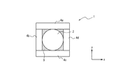
図6は、第2実施の形態に係る光走査用アクチュエータ1の光軸に垂直な面による断面図である。本実施の形態は、第1実施の形態と同様に、フェルール3の加工精度が不十分なため、光ファイバ2の光軸に対する断面形状が台形になっている。そこで、フェルール3の斜面となっている圧電素子4dが配置される面(図において+x側の面)に、接着剤9を用いて隙間を埋めるようにして、圧電素子4dを対向する圧電素子4bと平行になるように固着している。これによって、光走査用アクチュエータ1の共振方向と圧電素子4a〜4dの駆動力の方向とをx方向に一致させている。このとき、隙間を埋める素材は接着剤に限られず、またその材料の密度は、フェルール3の密度に近いことが好ましい。その他の構成は、第1実施の形態と同様であるので、同一または対応する構成要素には同一参照符号を付して説明を省略する。
図7は、第3実施の形態に係る光走査用アクチュエータ1の断面図である。本実施の形態では、フェルール3に圧電素子4bを貼り付ける段階において、意図せず貼付位置がずれてしまった場合を示している。この場合、圧電素子4bよりも後に貼り付ける圧電素子4dは、圧電素子4bよりも正確な位置決めが可能なものとする。図7のアクチュエータによれば、フェルール3の断面形状は実質的に正方形となっている。一方、x軸方向の圧電素子4b,4dに注目した場合、−x側の圧電素子4bが−y方向にずれている。そこで、+x側の圧電素子4dも同様に−y方向にずらすことで、光走査用アクチュエータ1の共振方向(D1)と圧電素子4b,4dの駆動力方向(D2)とをx方向にほぼ一致させている。これによって、共振周波数近傍で不所望な歪みや傾きを抑制した走査軌跡を得ることができ、効率的にファイバを振動させることが可能となる。なお、この場合も光走査用アクチュエータ1は回転非対称となっている。その他の構成は、第1実施の形態と同様であるので、同一または対応する構成要素には同一参照符号を付して説明を省略する。
図8は、第4実施の形態に係る光走査用アクチュエータ1の断面図である。この光走査用アクチュエータ1では、y方向に対向する圧電素子4aと4cのうち、一方の圧電素子4a(第1の圧電素子)を1枚で構成し、他方の圧電素子4cをx方向に並んで配列された2枚のz方向に長い圧電素子4c1,4c2(第2の圧電素子,第3の圧電素子)により構成する。また、同様に、x方向に対向する圧電素子4bと4dのうち、一方の圧電素子4bを1枚で構成し、他方の圧電素子4dをy方向に並んで配列された2枚のz方向に長い圧電素子4d1,4d2により構成する。これにより、光走査用アクチュエータ1は回転非対称となっている。ここで、フェルール3の形状は、断面が正方形の直方体が望ましく、圧電素子4aはフェルール3のy方向の面の中央に位置し、圧電素子4bはフェルール3の−x方向の面の中央に位置することが望ましい。しかし、上記各実施の形態と同様にこれらの形状および配置位置の精度を高めることは困難である。その他の構成は、第1実施の形態と同様であるので、同一または対応する構成要素には同一参照符号を付して説明を省略する。
図9は、第5実施の形態に係る光走査用アクチュエータ1の断面図である。この光走査用アクチュエータ1は、上記各実施の形態とは異なり、フェルールを用いることなく、光ファイバ2に圧電素子4a〜4dを接着剤9などで直接接着したものである。一般に、x方向、y方向に対向する圧電素子4a〜4dを平行に貼り付けることは非常に困難であり、圧電素子4a〜4dがx方向もしくはy方向から傾いてしまった場合、軌跡が楕円になるなど不具合が発生する。
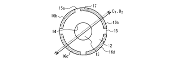
図10は、第6実施の形態に係る光走査用アクチュエータ11(光ファイバを除く)の斜視図である。また、図11は、図10の光走査用アクチュエータ11の製造過程における圧電材料の形状を説明する断面図である。さらに、図12は、図10の光走査用アクチュエータ11の断面図である。
図13は、第7実施の形態に係る光走査装置の一例である光走査型内視鏡装置20の概略構成を示すブロック図である。光走査型内視鏡装置20は、スコープ30と、制御装置本体40とディスプレイ50とによって構成されている。
2 光ファイバ
2a 先端部
3 フェルール
4a〜4d,4c1,4c2,4d1,4d2 圧電素子
5a〜5d 圧電材料
6a〜6d 電極
7 デバイス保持具
8a,8b 配線
9 接着剤
11 光走査用アクチュエータ
12 圧電材料
13 内腔
14 中央電極
15 凸部(分離領域)
16 電極
17 絶縁材
20 光走査型内視鏡装置
21 照明用光ファイバ
22 検出用光ファイバ
23 配線ケーブル
30 スコープ
31 駆動部
32 操作部
33 挿入部
34 先端部
35a、35b 投影用レンズ
36 取付環
37 アクチュエータ管
40 制御装置本体
41 制御部
42 発光タイミング制御部
43R、43G、43B レーザ
44 結合器
45 光検出器
46 ADC
47 画像処理部
48 駆動制御部
50 ディスプレイ
60 対象物
101 光走査用アクチュエータ
102 光ファイバ
1033 フェルール
104a〜104d 圧電素子
107 デバイス保持具
108a,108b 配線
Claims (5)
- 振動可能に支持された先端部を有する光ファイバと、
前記光ファイバの光軸方向に沿って伸縮することにより、前記光ファイバの前記先端部を前記光軸に垂直な方向に駆動させる駆動力を発生させる圧電素子と
を備え、
前記光ファイバの光軸回りに回転非対称かまたは2回回転対称性を有するように構成され、
前記光ファイバの前記先端部の共振方向と、前記圧電素子の前記駆動力の方向とが、実質的に平行であることを特徴とする光走査用アクチュエータ。 - 前記光ファイバの光軸回りに回転非対称に構成されていることを特徴とする請求項1に記載の光走査用アクチュエータ。
- 前記圧電素子は、第1の圧電素子と、前記光ファイバを挟み前記第1の圧電素子に対向して配置された第2の圧電素子および第3の圧電素子とを含むことを特徴とする請求項1または2に記載の光走査用アクチュエータ。
- 前記光ファイバを保持するフェルールを備え、前記圧電素子は、前記フェルールの側面に固定されていることを特徴とする請求項1〜3の何れか一項に記載の光走査用アクチュエータ。
- 請求項1〜4の何れか一項に記載の光走査用アクチュエータと、
前記光ファイバの前記先端部とは反対側の端部に、光源からの照明光を入射させる光入力部と、
前記光ファイバの前記先端部から射出される光を対象物に照射する光学系と、
前記圧電素子に印加する電圧を制御して、前記光ファイバの前記先端部を所望の走査軌跡となるように走査させる制御部と
を備えた光走査装置。
Priority Applications (5)
| Application Number | Priority Date | Filing Date | Title |
|---|---|---|---|
| JP2014130350A JP6438221B2 (ja) | 2014-06-25 | 2014-06-25 | 光走査用アクチュエータおよび光走査装置 |
| CN201580033508.4A CN106662742A (zh) | 2014-06-25 | 2015-06-22 | 光扫描用致动器和光扫描装置 |
| DE112015002540.5T DE112015002540T5 (de) | 2014-06-25 | 2015-06-22 | Aktor zum optischen Scannen und optisches Scan-Gerät |
| PCT/JP2015/003118 WO2015198585A1 (ja) | 2014-06-25 | 2015-06-22 | 光走査用アクチュエータおよび光走査装置 |
| US15/385,154 US20170102537A1 (en) | 2014-06-25 | 2016-12-20 | Optical scanning actuator and optical scanning apparatus |
Applications Claiming Priority (1)
| Application Number | Priority Date | Filing Date | Title |
|---|---|---|---|
| JP2014130350A JP6438221B2 (ja) | 2014-06-25 | 2014-06-25 | 光走査用アクチュエータおよび光走査装置 |
Publications (2)
| Publication Number | Publication Date |
|---|---|
| JP2016009121A true JP2016009121A (ja) | 2016-01-18 |
| JP6438221B2 JP6438221B2 (ja) | 2018-12-12 |
Family
ID=54937693
Family Applications (1)
| Application Number | Title | Priority Date | Filing Date |
|---|---|---|---|
| JP2014130350A Active JP6438221B2 (ja) | 2014-06-25 | 2014-06-25 | 光走査用アクチュエータおよび光走査装置 |
Country Status (5)
| Country | Link |
|---|---|
| US (1) | US20170102537A1 (ja) |
| JP (1) | JP6438221B2 (ja) |
| CN (1) | CN106662742A (ja) |
| DE (1) | DE112015002540T5 (ja) |
| WO (1) | WO2015198585A1 (ja) |
Cited By (4)
| Publication number | Priority date | Publication date | Assignee | Title |
|---|---|---|---|---|
| WO2017168809A1 (ja) * | 2016-03-31 | 2017-10-05 | オリンパス株式会社 | 光ファイバスキャナ、照明装置および観察装置 |
| WO2017195258A1 (ja) * | 2016-05-09 | 2017-11-16 | オリンパス株式会社 | 光ファイバスキャナ、照明装置および観察装置 |
| JP2019120722A (ja) * | 2017-12-28 | 2019-07-22 | 株式会社日立製作所 | 光走査装置及び映像装置 |
| JP2020503548A (ja) * | 2016-12-22 | 2020-01-30 | マジック リープ, インコーポレイテッドMagic Leap,Inc. | 走査ファイバディスプレイのための成形ファイバ要素の製作のための方法およびシステム |
Families Citing this family (12)
| Publication number | Priority date | Publication date | Assignee | Title |
|---|---|---|---|---|
| WO2016116963A1 (ja) * | 2015-01-21 | 2016-07-28 | オリンパス株式会社 | 光走査方法及び光走査装置 |
| US11150464B2 (en) * | 2017-06-13 | 2021-10-19 | Mitsubishi Electric Corporation | Optical scanning device and method of adjusting optical scanning device |
| WO2019246380A1 (en) * | 2018-06-20 | 2019-12-26 | Magic Leap, Inc. | Methods and systems for fiber scanners with continuous bond lines |
| CN110687676B (zh) * | 2018-07-06 | 2021-10-08 | 成都理想境界科技有限公司 | 一种光纤扫描驱动器、光纤扫描模组和投影设备 |
| CN109951101B (zh) * | 2019-04-09 | 2020-03-06 | 哈尔滨工业大学 | 压电驱动的超精密四自由度定位调姿机构及其激励方法 |
| CN116520557A (zh) * | 2019-09-30 | 2023-08-01 | 成都理想境界科技有限公司 | 一种致动器及光纤扫描器 |
| CN114384692B (zh) * | 2020-10-21 | 2024-10-29 | 成都理想境界科技有限公司 | 一种扫描致动器及光纤扫描器 |
| KR102525658B1 (ko) * | 2021-02-15 | 2023-04-26 | 광주과학기술원 | 광섬유 지향장치 및 광섬유 지향장치를 이용하는 레이저빔결합장치 |
| WO2022190259A1 (ja) * | 2021-03-10 | 2022-09-15 | オリンパス株式会社 | レーザ走査方法、レーザ照射装置およびレーザ治療システム |
| CN113156639A (zh) * | 2021-03-29 | 2021-07-23 | 成都理想境界科技有限公司 | 扫描致动器、光纤扫描器及扫描显示模组 |
| US20240366071A1 (en) * | 2021-08-10 | 2024-11-07 | Hang An Medtech (Hangzhou) Co., Ltd. | Scanning fiber endoscope probes and scanning fiber endoscopes |
| CN115576098B (zh) * | 2022-09-27 | 2025-11-25 | 成都理想境界科技有限公司 | 一种扫描致动器及光纤扫描器 |
Citations (2)
| Publication number | Priority date | Publication date | Assignee | Title |
|---|---|---|---|---|
| WO2013069382A1 (ja) * | 2011-11-09 | 2013-05-16 | オリンパス株式会社 | 内視鏡及び内視鏡装置 |
| JP2014071423A (ja) * | 2012-10-01 | 2014-04-21 | Olympus Corp | 光ファイバスキャナ |
Family Cites Families (13)
| Publication number | Priority date | Publication date | Assignee | Title |
|---|---|---|---|---|
| JP3293305B2 (ja) * | 1994-03-07 | 2002-06-17 | 松下電器産業株式会社 | ディジタル無線電話装置 |
| JP2001174744A (ja) * | 1999-10-06 | 2001-06-29 | Olympus Optical Co Ltd | 光走査プローブ装置 |
| US7635778B2 (en) * | 2004-12-17 | 2009-12-22 | Sabic Innovative Plastics Ip B.V. | Composition, method of authenticating, methods of making authenticatable compositions, authenticatable articles made there from |
| JP4935013B2 (ja) * | 2005-07-21 | 2012-05-23 | ブラザー工業株式会社 | 光走査装置、画像表示装置及び光スキャナの共振周波数変更方法並びに反射ミラー位置の補正方法 |
| US20080058629A1 (en) * | 2006-08-21 | 2008-03-06 | University Of Washington | Optical fiber scope with both non-resonant illumination and resonant collection/imaging for multiple modes of operation |
| JP2011030720A (ja) * | 2009-07-31 | 2011-02-17 | Hoya Corp | 医療用観察システム |
| CN103781397B (zh) * | 2012-06-28 | 2016-08-17 | 奥林巴斯株式会社 | 扫描型内窥镜和扫描型内窥镜的制造方法 |
| EP2905648A4 (en) * | 2012-10-01 | 2016-06-22 | Olympus Corp | FIBER OPTIC SCANNING DEVICE |
| JP5639310B2 (ja) * | 2012-10-22 | 2014-12-10 | オリンパスメディカルシステムズ株式会社 | 走査型内視鏡システム |
| WO2014065077A1 (ja) * | 2012-10-22 | 2014-05-01 | オリンパスメディカルシステムズ株式会社 | 走査型内視鏡システム及び走査型内視鏡システムの作動方法 |
| KR102067759B1 (ko) * | 2013-02-15 | 2020-01-17 | 삼성전자주식회사 | 파이버 스캐닝 프로젝터 |
| JP5765756B2 (ja) * | 2013-07-12 | 2015-08-19 | オリンパス株式会社 | 走査型内視鏡 |
| JP6298535B2 (ja) * | 2013-12-27 | 2018-03-20 | ユニヴァーシティ・オブ・ワシントン・スルー・イッツ・センター・フォー・コマーシャリゼーション | 圧電検知を伴うファイバスキャナの適応的制御 |
-
2014
- 2014-06-25 JP JP2014130350A patent/JP6438221B2/ja active Active
-
2015
- 2015-06-22 DE DE112015002540.5T patent/DE112015002540T5/de not_active Withdrawn
- 2015-06-22 CN CN201580033508.4A patent/CN106662742A/zh active Pending
- 2015-06-22 WO PCT/JP2015/003118 patent/WO2015198585A1/ja not_active Ceased
-
2016
- 2016-12-20 US US15/385,154 patent/US20170102537A1/en not_active Abandoned
Patent Citations (2)
| Publication number | Priority date | Publication date | Assignee | Title |
|---|---|---|---|---|
| WO2013069382A1 (ja) * | 2011-11-09 | 2013-05-16 | オリンパス株式会社 | 内視鏡及び内視鏡装置 |
| JP2014071423A (ja) * | 2012-10-01 | 2014-04-21 | Olympus Corp | 光ファイバスキャナ |
Cited By (8)
| Publication number | Priority date | Publication date | Assignee | Title |
|---|---|---|---|---|
| WO2017168809A1 (ja) * | 2016-03-31 | 2017-10-05 | オリンパス株式会社 | 光ファイバスキャナ、照明装置および観察装置 |
| WO2017195258A1 (ja) * | 2016-05-09 | 2017-11-16 | オリンパス株式会社 | 光ファイバスキャナ、照明装置および観察装置 |
| JPWO2017195258A1 (ja) * | 2016-05-09 | 2018-11-29 | オリンパス株式会社 | 光ファイバスキャナ、照明装置および観察装置 |
| JP2020503548A (ja) * | 2016-12-22 | 2020-01-30 | マジック リープ, インコーポレイテッドMagic Leap,Inc. | 走査ファイバディスプレイのための成形ファイバ要素の製作のための方法およびシステム |
| JP7036825B2 (ja) | 2016-12-22 | 2022-03-15 | マジック リープ, インコーポレイテッド | 走査ファイバディスプレイのための成形ファイバ要素の製作のための方法およびシステム |
| US11442227B2 (en) | 2016-12-22 | 2022-09-13 | Magic Leap, Inc. | Methods and systems for fabrication of shaped fiber elements for scanning fiber displays |
| JP2019120722A (ja) * | 2017-12-28 | 2019-07-22 | 株式会社日立製作所 | 光走査装置及び映像装置 |
| JP7058122B2 (ja) | 2017-12-28 | 2022-04-21 | 株式会社日立製作所 | 光走査装置及び映像装置 |
Also Published As
| Publication number | Publication date |
|---|---|
| CN106662742A (zh) | 2017-05-10 |
| US20170102537A1 (en) | 2017-04-13 |
| JP6438221B2 (ja) | 2018-12-12 |
| DE112015002540T5 (de) | 2017-02-23 |
| WO2015198585A1 (ja) | 2015-12-30 |
Similar Documents
| Publication | Publication Date | Title |
|---|---|---|
| JP6438221B2 (ja) | 光走査用アクチュエータおよび光走査装置 | |
| CN103781397B (zh) | 扫描型内窥镜和扫描型内窥镜的制造方法 | |
| JP6086674B2 (ja) | 光走査装置 | |
| JP6057743B2 (ja) | 光走査装置 | |
| JP6274949B2 (ja) | 光ファイバスキャナ、照明装置および観察装置 | |
| CN104620156A (zh) | 光纤扫描仪 | |
| US10288876B2 (en) | Optical scanning actuator and optical scanning apparatus | |
| US10330916B2 (en) | Optical-fiber scanner, illumination apparatus, and observation apparatus | |
| WO2015182137A1 (ja) | 光走査型内視鏡装置 | |
| JP6226730B2 (ja) | 光走査装置および光走査型観察装置 | |
| US20170238792A1 (en) | Optical fiber scanner, illuminating device, and observation apparatus | |
| US20180252910A1 (en) | Optical fiber scanner, illumination device, and observation device | |
| JP6218546B2 (ja) | 光走査方法、光走査装置および光走査型観察装置 | |
| JP2016009012A (ja) | 光走査用アクチュエータ、光走査装置、及び光走査用アクチュエータの製造方法 | |
| JP6006039B2 (ja) | 光走査型観察装置 | |
| CN106455932A (zh) | 光扫描装置和光扫描型观察装置 | |
| WO2016116963A1 (ja) | 光走査方法及び光走査装置 | |
| JP6081679B1 (ja) | 光走査型観察システム | |
| JP6006127B2 (ja) | 光走査装置 | |
| JPWO2016116962A1 (ja) | 光走査方法及び光走査装置 | |
| WO2017029691A1 (ja) | 光走査方法、光走査装置および光走査型観察装置 | |
| WO2017103962A1 (ja) | 光走査用アクチュエータ、光走査装置、及び光走査用アクチュエータの製造方法 | |
| JPWO2016084116A1 (ja) | 光走査用アクチュエータ及び光走査装置 | |
| JPWO2018073948A1 (ja) | 光ファイバスキャナ、照明装置および観察装置 |
Legal Events
| Date | Code | Title | Description |
|---|---|---|---|
| A621 | Written request for application examination |
Free format text: JAPANESE INTERMEDIATE CODE: A621 Effective date: 20170228 |
|
| A131 | Notification of reasons for refusal |
Free format text: JAPANESE INTERMEDIATE CODE: A131 Effective date: 20180109 |
|
| A521 | Request for written amendment filed |
Free format text: JAPANESE INTERMEDIATE CODE: A523 Effective date: 20180307 |
|
| A131 | Notification of reasons for refusal |
Free format text: JAPANESE INTERMEDIATE CODE: A131 Effective date: 20180904 |
|
| A521 | Request for written amendment filed |
Free format text: JAPANESE INTERMEDIATE CODE: A523 Effective date: 20181030 |
|
| TRDD | Decision of grant or rejection written | ||
| A01 | Written decision to grant a patent or to grant a registration (utility model) |
Free format text: JAPANESE INTERMEDIATE CODE: A01 Effective date: 20181113 |
|
| A61 | First payment of annual fees (during grant procedure) |
Free format text: JAPANESE INTERMEDIATE CODE: A61 Effective date: 20181116 |
|
| R151 | Written notification of patent or utility model registration |
Ref document number: 6438221 Country of ref document: JP Free format text: JAPANESE INTERMEDIATE CODE: R151 |
|
| R250 | Receipt of annual fees |
Free format text: JAPANESE INTERMEDIATE CODE: R250 |
|
| R250 | Receipt of annual fees |
Free format text: JAPANESE INTERMEDIATE CODE: R250 |
|
| R250 | Receipt of annual fees |
Free format text: JAPANESE INTERMEDIATE CODE: R250 |
|
| R250 | Receipt of annual fees |
Free format text: JAPANESE INTERMEDIATE CODE: R250 |
|
| R250 | Receipt of annual fees |
Free format text: JAPANESE INTERMEDIATE CODE: R250 |