JP2016061237A - Waste-heat power generating apparatus - Google Patents
Waste-heat power generating apparatus Download PDFInfo
- Publication number
- JP2016061237A JP2016061237A JP2014190326A JP2014190326A JP2016061237A JP 2016061237 A JP2016061237 A JP 2016061237A JP 2014190326 A JP2014190326 A JP 2014190326A JP 2014190326 A JP2014190326 A JP 2014190326A JP 2016061237 A JP2016061237 A JP 2016061237A
- Authority
- JP
- Japan
- Prior art keywords
- grease
- circulation path
- casing
- bearing
- waste heat
- Prior art date
- Legal status (The legal status is an assumption and is not a legal conclusion. Google has not performed a legal analysis and makes no representation as to the accuracy of the status listed.)
- Pending
Links
Images

Landscapes
- Engine Equipment That Uses Special Cycles (AREA)
Abstract
Description
本発明は、廃熱エネルギーを用いて発電を行う廃熱発電装置に関する。 The present invention relates to a waste heat power generation apparatus that generates power using waste heat energy.
従来、工場や焼却施設等で放出される廃熱エネルギーを回収して発電が行われる廃熱発電装置が開発されている。例えば、特許文献1には、廃熱エネルギーにより作動媒体を蒸発させる蒸発器と、蒸発器で蒸発した作動媒体(蒸気)により発電機を発電させるタービン発電機と、タービン発電機から排出された作動媒体(蒸気)を凝縮する凝縮器と、凝縮器で凝縮された作動媒体(凝縮液)を蒸発器に送出するポンプとを備えた廃熱発電装置が提案されている。 2. Description of the Related Art Conventionally, a waste heat power generation apparatus has been developed that generates power by collecting waste heat energy released in factories, incineration facilities, and the like. For example, Patent Document 1 discloses an evaporator that evaporates a working medium by waste heat energy, a turbine generator that generates a generator using a working medium (steam) evaporated by the evaporator, and an operation discharged from the turbine generator. A waste heat power generation apparatus including a condenser that condenses a medium (steam) and a pump that sends a working medium (condensate) condensed in the condenser to an evaporator has been proposed.
タービン発電機は、作動媒体(蒸気)により回転されるインペラと、インペラに固定されて一体回転するシャフトと、シャフトに接続された発電機と、シャフトを回転自在に支持する軸受と、インペラ、シャフト、発電機、軸受が内部に収容されるケーシングとを含んで構成される。そして、軸受には、廃熱発電装置の作動中に、外部に設けられたグリス供給装置からグリス供給路を介してグリスが供給され、円滑な回転が維持されている。 The turbine generator includes an impeller that is rotated by a working medium (steam), a shaft that is fixed to the impeller and integrally rotates, a generator that is connected to the shaft, a bearing that rotatably supports the shaft, an impeller, and a shaft. A generator and a casing in which the bearing is housed. Then, during the operation of the waste heat power generation apparatus, the grease is supplied from the grease supply apparatus provided outside via the grease supply path, and smooth rotation is maintained.
ところで、上記の廃熱発電装置では、作動媒体が循環する循環経路に作動媒体を封入する際、循環経路内の空気を取り除くため真空ポンプにより真空引きが行われる。このとき、グリス供給路にグリスが充填されていると、グリスがケーシング内に引き込まれてしまい、その後の廃熱発電装置の作動中に、軸受にグリスが適切に供給されないおそれがある。 By the way, in the above waste heat power generation apparatus, when the working medium is sealed in the circulation path through which the working medium circulates, vacuuming is performed by a vacuum pump in order to remove air in the circulation path. At this time, if the grease supply path is filled with grease, the grease is drawn into the casing, and the grease may not be properly supplied to the bearing during the subsequent operation of the waste heat power generation apparatus.
そこで本発明は、このような課題に鑑み、軸受にグリスを適切に供給することが可能な廃熱発電装置を提供することを目的としている。 Then, in view of such a subject, an object of the present invention is to provide a waste heat power generator which can supply grease to a bearing appropriately.
上記課題を解決するために、本発明の廃熱発電装置は、作動媒体の循環経路と、循環経路に設けられ、ケーシング内に軸受を収容するタービン発電機と、循環経路またはケーシングと連通する真空ポンプと、軸受と接続されたグリス供給路と、グリス供給路と接続され、密閉容器に収納されたグリス供給装置と、循環経路またはケーシングの圧力と密閉容器の圧力の調整を行う調整手段と、を有する。当該調整手段によって、循環経路またはケーシングの圧力と密閉容器の圧力が調整されるため、グリスがケーシング内に引き込まれることを抑制することができ、上記課題が解決される。 In order to solve the above-described problems, a waste heat power generation apparatus according to the present invention includes a circulation path of a working medium, a turbine generator provided in the circulation path and housing a bearing in the casing, and a vacuum communicating with the circulation path or the casing. A grease supply path connected to the pump, a bearing, a grease supply apparatus connected to the grease supply path and housed in a sealed container, and an adjusting means for adjusting the pressure of the circulation path or casing and the pressure of the sealed container; Have Since the adjustment means adjusts the pressure of the circulation path or casing and the pressure of the closed container, it is possible to prevent the grease from being drawn into the casing, and the above-described problem is solved.
また、調整手段は、循環経路またはケーシングと密閉容器を接続する連通管であるとよい。 The adjusting means may be a communication pipe that connects the circulation path or casing and the sealed container.
また、真空ポンプは第1の真空ポンプであり、調整手段は、密閉容器に連通する第2の真空ポンプであるとよい。 The vacuum pump may be a first vacuum pump, and the adjusting means may be a second vacuum pump communicating with the sealed container.
また、調整手段は、循環経路またはケーシングの圧力と、密閉容器の圧力とが略等しくなるように調整を行うとよい。 The adjusting means may adjust the pressure of the circulation path or the casing and the pressure of the closed container to be substantially equal.
また、調整手段は、グリス供給路の両端に圧力差が発生しないように、調整を行うとよい。 Further, the adjusting means may adjust so that a pressure difference does not occur at both ends of the grease supply path.
また、別の観点から本発明の廃熱発電装置は、作動媒体が循環する循環経路上に設けられ、循環経路上に設けられた蒸発器で外部から供給される熱源により蒸気にされた作動媒体で回転されるインペラと、インペラと一体回転するシャフトと、シャフトの回転により発電する発電機と、シャフトを回転自在に支持する軸受と、循環経路の一部を構成するとともにインペラ、シャフト、発電機および軸受が収納されるケーシングと、軸受にグリスを供給するグリス供給装置と、グリス供給装置の少なくともグリスを供給する部位を密閉する密閉容器と、グリス供給装置から軸受にグリスを供給するためのグリス供給路と、循環経路またはケーシングに連通され、循環経路に作動媒体が封入される前に、循環経路を真空引きする真空ポンプと、循環経路またはケーシングと、密閉容器とを連通させる連通管とを備える。 From another point of view, the waste heat power generation apparatus of the present invention is provided on a circulation path through which the working medium circulates, and is a working medium that has been vaporized by a heat source supplied from the outside by an evaporator provided on the circulation path. The impeller rotated by the shaft, the shaft that rotates integrally with the impeller, the generator that generates power by the rotation of the shaft, the bearing that supports the shaft rotatably, the part of the circulation path and the impeller, shaft, and generator And a casing in which the bearing is housed, a grease supply device that supplies grease to the bearing, a sealed container that seals at least a portion of the grease supply device that supplies grease, and a grease for supplying grease from the grease supply device to the bearing A vacuum pump that communicates with the supply path, the circulation path or the casing, and evacuates the circulation path before the working medium is sealed in the circulation path; It includes a path or casing, and a communicating tube communicating the sealed container.
また、さらに別の観点から本発明の廃熱発電装置は、作動媒体が循環する循環経路上に設けられ、循環経路上に設けられた蒸発器で外部から供給される熱源により蒸気にされた作動媒体で回転されるインペラと、インペラと一体回転するシャフトと、シャフトの回転により発電する発電機と、シャフトを回転自在に支持する軸受と、循環経路の一部を構成するとともにインペラ、シャフト、発電機および軸受が収納されるケーシングと、軸受にグリスを供給するグリス供給装置と、グリス供給装置の少なくともグリスを供給する部位を密閉する密閉容器と、グリス供給装置から軸受にグリスを供給するためのグリス供給路と、循環経路またはケーシングに連通され、循環経路に作動媒体が封入される前に、循環経路を真空引きする第1の真空ポンプと、密閉容器に連通され、第1の真空ポンプにより循環経路が真空引きされる際に、循環経路の圧力に対して密閉容器内の圧力を所定の圧力差内に維持した状態で、密閉容器内を真空引きする第2の真空ポンプとを備える。 Further, from another viewpoint, the waste heat power generation apparatus of the present invention is provided on a circulation path through which the working medium circulates, and is operated by a heat source supplied from the outside by an evaporator provided on the circulation path. An impeller that is rotated by a medium, a shaft that rotates integrally with the impeller, a generator that generates electric power by rotating the shaft, a bearing that rotatably supports the shaft, a part of the circulation path, and the impeller, shaft, and power generation A casing in which the machine and the bearing are stored, a grease supply device that supplies grease to the bearing, a sealed container that seals at least a portion of the grease supply device that supplies grease, and a grease supply device that supplies grease to the bearing A first vacuum that communicates with the grease supply path and the circulation path or casing, and evacuates the circulation path before the working medium is sealed in the circulation path. When the circulating path is evacuated by the first vacuum pump, the sealed container is sealed in a state where the pressure in the sealed container is maintained within a predetermined pressure difference with respect to the pressure of the circulating path. A second vacuum pump for evacuating the inside of the container.
本発明によれば、循環経路またはケーシングの圧力と密閉容器の圧力が調整されるため、グリスがケーシング内に引き込まれることを抑制することができ、軸受にグリスを適切に供給することが可能となる。 According to the present invention, since the pressure of the circulation path or the casing and the pressure of the sealed container are adjusted, it is possible to prevent the grease from being drawn into the casing and to supply the grease appropriately to the bearing. Become.
以下に添付図面を参照しながら、本発明の好適な実施形態について詳細に説明する。かかる実施形態に示す寸法、材料、その他具体的な数値等は、発明の理解を容易とするための例示にすぎず、特に断る場合を除き、本発明を限定するものではない。なお、本明細書および図面において、実質的に同一の機能、構成を有する要素については、同一の符号を付することにより重複説明を省略し、また本発明に直接関係のない要素は図示を省略する。 Hereinafter, preferred embodiments of the present invention will be described in detail with reference to the accompanying drawings. The dimensions, materials, and other specific numerical values shown in the embodiments are merely examples for facilitating the understanding of the invention, and do not limit the present invention unless otherwise specified. In the present specification and drawings, elements having substantially the same function and configuration are denoted by the same reference numerals, and redundant description is omitted, and elements not directly related to the present invention are not illustrated. To do.
<第1の実施形態>
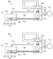
図1は、第1の実施形態における廃熱発電装置100の全体構成を示す概略図である。図1に示すように、廃熱発電装置100は、蒸発器102、タービン発電機104、凝縮器106、ポンプ108、グリス供給装置110、流路112(112a〜112d)、真空ポンプ114、連通管116を含んで構成される。廃熱発電装置100は、ランキンサイクルを利用し、工場や焼却施設等から放出される約300℃以下の温水(低温廃熱)を用いて発電を行う。
<First Embodiment>
FIG. 1 is a schematic diagram illustrating an overall configuration of a waste heat
廃熱発電装置100では、蒸発器102、タービン発電機104、凝縮器106、ポンプ108が流路112を介して連通されている。具体的には、蒸発器102とタービン発電機104とが流路112aを介して連通され、タービン発電機104と凝縮器106とが流路112bを介して連通され、凝縮器106とポンプ108とが流路112cを介して連通され、ポンプ108と蒸発器102とが流路112dを介して連通されている。そして、廃熱発電装置100では、流路112を介して、蒸発器102、タービン発電機104、凝縮器106およびポンプ108の順に作動媒体が循環する。
In the waste heat
ここで、廃熱発電装置100で用いられる作動媒体は、沸点(大気圧条件下における沸点)が90℃以下の媒体を用い、かつ、詳しくは後述する循環経路の圧力が最大で1MPa(G)(ゲージ圧で1MPa)以下であることが望ましい。例えば、作動媒体は、ハイドロフルオロエーテル(HFE)、フルオロカーボン、フルオロケトン、パーフルオロポリエーテル等を適応することができる。
Here, the working medium used in the waste heat
蒸発器102は、熱源流路120が内部に配されており、工場等の外部から放出される温水(低温廃熱)が熱源流路120に流入(供給)される。そして、蒸発器102では、熱源流路120を流れる温水により、作動媒体(凝縮液)が蒸発する。蒸発した作動媒体(蒸気)は、流路112aに排出され、流路112aを介してタービン発電機104に導入される。
The
タービン発電機104は、各部がケーシング140内に収容、密閉され、蒸発器102で蒸発し、流路112aを介して導入された作動媒体(蒸気)によりインペラ130が回転され、インペラ130にシャフト132を介して接続された発電機134により発電を行う。インペラ130を回転させた作動媒体(蒸気)は、流路112bに排出され、流路112bを介して凝縮器106に導入される。なお、タービン発電機104の詳細な構成については後述する。
Each part of the
凝縮器106は、冷却水が流入される冷水源流路122が内部に配されており、流路112bを介して導入された作動媒体(蒸気)を、冷水源流路122を流れる冷水により冷却して凝縮させる。凝縮器106で凝縮した作動媒体(凝縮液)は、流路112cに排出され、流路112cを介してポンプ108に導入される。
The
ポンプ108は、凝縮器106で凝縮し、流路112cを介して導入された作動媒体(凝縮液)を加圧し、流路112dを介して蒸発器102に向けて送出する。
The
グリス供給装置110は、密閉容器110a内に収納され、タービン発電機104に設けられている軸受136、138にグリスを供給する。
The
真空ポンプ114は、ケーシング140と連通され、詳しくは後述するように、廃熱発電装置100の作動前に、蒸発器102、タービン発電機104、凝縮器106、ポンプ108および流路112内を真空引きする。連通管116は、密閉容器110aとケーシング140とを連通する管であり、密閉容器110aとケーシング140とが一体となって密閉される。ここで、連通管116は、本発明の調整手段の一例である。調整手段は、後述の第2の実施形態で説明される真空ポンプ502であってもよく、一般的には、循環経路204またはケーシング140の圧力と密閉容器110aの圧力の調整を行うものであれば、その他の例も含む。
The
このように、廃熱発電装置100では、ポンプ108によって作動媒体が蒸発器102に送出され、蒸発器102に導入される温水(低温廃熱)の廃熱エネルギーによって作動媒体(凝縮液)が沸騰蒸発する。蒸発器102で蒸発した作動媒体(蒸気)は、タービン発電機104に供給されてタービン発電機104のインペラ130を回転駆動し、タービン発電機104の発電機134で発電が行われる。タービン発電機104を介した作動媒体(蒸気)は、凝縮器106で冷却水によって冷却されることにより凝縮する。凝縮器106によって凝縮された作動媒体(凝縮液)は、ポンプ108によって加圧されて再び蒸発器102に向けて送出される。このように、廃熱発電装置100では、作動媒体の蒸発および凝縮が繰り返され、ランキンサイクルにより、低温廃熱の廃熱エネルギーを用いた発電が行われる。
As described above, in the waste heat
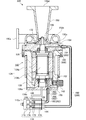
図2は、タービン発電機104およびグリス供給装置110の構成を示す説明図である。なお、図2では、タービン発電機104およびグリス供給装置110を側断面図で図示している。
FIG. 2 is an explanatory diagram showing configurations of the
図2に示すように、タービン発電機104は、インペラ130、シャフト132、発電機134、軸受136、138、ケーシング140、コネクタ142、予圧バネ144を含んで構成される。インペラ130は、蒸発器102で蒸発した作動媒体(蒸気)により回転駆動される回転翼である。具体的には、インペラ130は、径方向外側から供給される作動媒体(蒸気)により回転駆動され、回転軸方向の一方側から膨張した作動媒体(蒸気)を排出する。
As shown in FIG. 2, the
シャフト132は、インペラ130の回転軸方向に延在して設けられており、一端部にはインペラ130がネジ止め等で固定されており、インペラ130と一体回転する。
The
発電機134は、シャフト132の外周面に沿って配列された複数の永久磁石を有してシャフト132に固定されたロータ134aと、ロータ134aの外周面に対向するように配列された複数のコイルを有してケーシング140に固定されたステータ134bとにより構成される。発電機134は、インペラ130の回転駆動力によりロータ134aが回転され、ロータ134aとステータ134bとの回転方向の相対的な位置が変化することで発電が行われる。
The
軸受136、138は、ケーシング140内に設置されており、シャフト132を回転自在に支持する。軸受136、138は、転がり軸受であり、例えば、アンギュラ玉軸受が適応される。なお、軸受136、138は、アンギュラ玉軸受に限らず、深溝玉軸受、円錐ころ軸受等のラジアル荷重およびスラスト荷重が支持できる軸受を適応してもよい。
The
軸受136は、インペラ130が固定されたシャフト132の一端部側を支持しており、軸受138は、シャフト132の他端部側を支持している。軸受136、138には、グリス供給装置110から、円滑な回転を維持するためのグリスがそれぞれ供給される。
The
ケーシング140は、インペラ130、シャフト132、発電機134、軸受136、138を収容する。ケーシング140は、スクロールケーシング150、ケーシング本体152、軸受支持部154、156を含んで構成される。
The
スクロールケーシング150は、吸入口150a、スクロール室150b、ノズル150cおよび排出口150dが形成されており、インペラ130の一方側を囲むように設けられる。吸入口150aは、流路112aに連通され、蒸発器102で蒸発しインペラ130を回転駆動する作動媒体(蒸気)が導入される。スクロール室150bは、インペラ130を囲んで環状に形成されており、一端が吸入口150aに連通され、他端がノズル150cに連通される。ノズル150cは、インペラ130を囲んで環状に形成されており、スクロール室150bを介して作動媒体(蒸気)が導入される。排出口150dは、流路112cに連通され、インペラ130を回転駆動した後の膨張した作動媒体(蒸気)が流路112cに排出される。
The
ケーシング本体152には、略円筒形状に形成され、発電機134およびシャフト132が収容されている。また、ケーシング本体152には、タービン発電機104で発電された電力を外部に取り出すためのコネクタ142が形成されている。タービン発電機104の外部からコネクタ142にケーブル(図示せず)が接続されることにより、発電機134で発電された電力がケーブルを介して外部に取り出される。なお、コネクタ142と発電機134のステータ134bに設けられたコイルとは、所定の配線によって電気的に接続されている。
The casing
軸受支持部154は、一側面にスクロールケーシング150が締結ボルト等を用いて着脱自在に取り付けられ、他側面にケーシング本体152が締結ボルト等を用いて着脱自在に取り付けられる。軸受支持部154の中央部には、軸受136が設置されており、シャフト132は、軸受支持部154を貫通した状態で軸受136に回転自在に支持されている。
The
軸受支持部156は、有底の円筒状に形成され、ケーシング本体152の軸受支持部154が取り付けられる側とは反対側に、円筒部156aがケーシング本体152内に配設されるように、その底部156bが締結ボルト等を用いて着脱自在に取り付けられる。軸受支持部156の円筒部156a内における空間の開口部には、軸受138が配置されており、シャフト132は、その一部が空間に介挿された状態で軸受138に回転自在に支持されている。
The
軸受支持部156の空間内には、軸受138を軸受136側に向かって付勢する予圧バネ144が設けられている。なお、軸受138はシャフト132を介して軸受136と連結されているため、予圧バネ144の付勢力は軸受138だけでなく軸受136にも伝わり、軸受136、138の双方に対して回転軸方向の付勢力が加えられる。上記したように、軸受136、138はアンギュラ玉軸受であることから、回転軸方向に適切な付勢力が加えられることで、転動体(玉)が適切な位置に保持され、回転に伴う振動や騒音等が低減される。
In the space of the
ここで、軸受支持部154、156には、円滑な回転を可能にするグリスを軸受136、138に供給するグリス流路160、162がそれぞれ形成されている。グリス流路160は、一端が軸受支持部154の中央部に配置された軸受136の上方に配設され、他端が軸受支持部154の外周上に設けられたグリス供給口164に連通するようにL字形に形成されている。グリス流路162は、一端が軸受支持部156の円筒部156a内に配置された軸受138の外周近傍に配設され、他端が軸受支持部156の底部156bに設けられたグリス供給口166に連通するように形成されている。
Here,
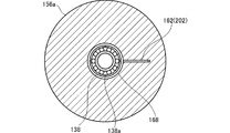
図3は、図2のIII−III線断面を示した図である。図3に示すように、軸受支持部156には、軸受138を囲むように環状流路168が形成されている。グリス流路162は、一端が環状流路168に連通し、他端がグリス供給口166に連通している。これにより、グリス供給口166からグリス流路162を介して供給されたグリスが、環状流路168を介して軸受138の径方向外側の全周に亘って供給される。
FIG. 3 is a cross-sectional view taken along line III-III in FIG. As shown in FIG. 3, an
また、軸受138の外輪には、径方向に向けて貫通する複数の貫通孔138aが形成されている。よって、環状流路168内のグリスが、複数の貫通孔138aを介して軸受138の内部に供給され、転動体(玉)の円滑な転動を維持することが可能となる。
The outer ring of the
図2に戻って説明すると、グリス供給装置110は、ケーシング140の外部に設置され、軸受136、138にグリスを供給する。このグリス供給装置110は、一対のシリンジ170、ピストン172、コンロッド174、駆動装置176を含んで構成され、これらが密閉容器110a内に収容、密閉されている。
Referring back to FIG. 2, the
一対のシリンジ170には、それぞれ第1供給管180および第2供給管182が接続されている。第1供給管180は、一方のシリンジ170と軸受支持部154のグリス供給口164とが連結されている。また、第2供給管182は、他方のシリンジ170と軸受支持部156のグリス供給口166とが連結されている。
A
また、第1供給管180のシリンジ170側の一端部にはバルブ184が設けられ、バルブ184が開閉されることにより、第1供給管180内の流路が開放および閉鎖される。第2供給管182のシリンジ170側の一端部にはバルブ186が設けられ、バルブ186が開閉されることにより、第2供給管182内の流路が開放および閉鎖される。なお、バルブ184、186は、バルブ開閉装置(図示せず)または手動により開閉される。なお、駆動装置176は、軸受136、138にグリスを連続的に供給するように駆動してもよい。
Further, a
シリンジ170内には、グリスが充填されており、駆動装置176が駆動することにより、コンロッド174を介してピストン172が駆動装置176とは反対側に移動される。そうすると、シリンジ170内のグリスが加圧され、第1供給管180、第2供給管182を介して軸受136、138にグリスが供給される。駆動装置176は、所定間隔毎に、予め設定された一定量を軸受136、138に供給するように駆動される。なお、ピストン172は、コンロッド174とは相対的に移動可能にシリンジ170内に配置されており、駆動装置176の駆動によりコンロッド174がピストン172側に移動して当接した後、さらにコンロッド174が移動すると、コンロッド174の移動に伴って移動する。
The
次に、主に、廃熱発電装置100の作動前に、循環経路に作動媒体が封入される際のグリス供給方法について説明する。
Next, the grease supply method when the working medium is sealed in the circulation path before the operation of the waste heat
以下では、グリス供給装置110から軸受136にグリスを供給するための流路であるグリス流路160、グリス供給口164および第1供給管180をまとめてグリス供給路200ともよぶ。また、グリス供給装置110から軸受138にグリスを供給するための流路であるグリス流路162、グリス供給口166、環状流路168および第2供給管182をまとめてグリス供給路202ともよぶ。また、蒸発器102、タービン発電機104、凝縮器106、ポンプ108および流路112のうち、作動媒体が循環する流路を循環経路ともよぶ。また、グリス供給路202側についてのグリス供給方法について説明し、グリス供給路200側についてはグリス供給路202側と同様であるため説明は省略する。
Hereinafter, the
ところで、廃熱発電装置100では、作動前(発電前)の初期設定時に、循環経路に作動媒体が封入される。廃熱発電装置100では、循環経路に空気等が混在していると、廃熱発電装置100の発電効率が低下するため、循環経路に作動媒体が封入される際、一旦、真空ポンプにより循環経路が真空引きされ、循環経路が真空となった状態で、外部から作動媒体が循環経路に注入される。
By the way, in the waste
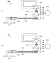
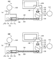
図4は、従来の廃熱発電装置300を示す説明図である。図4(a)に示すように、従来の廃熱発電装置300は、第1の実施形態における廃熱発電装置100と比較して、密閉容器110aおよび連通管116が設けられていない。廃熱発電装置300では、循環経路204に作動媒体が封入される際、グリス供給路202にグリスGR(図中、ハッチングで示す)が予め充填される。そして、ケーシング140に連通された真空ポンプ114が作動され、循環経路204が真空引きされる。そうすると、図4(b)に示すように、ケーシング140内が負圧(真空)になり、グリス供給路202内のグリスGRがケーシング140内に引きこまれ、また、ピストン172がバルブ186側に移動する。そして、廃熱発電装置300では、循環経路204に作動媒体が封入された後、作動を開始すると、所定間隔毎に一定量ずつグリスGRを軸受138に供給すべく、駆動装置176を駆動させてコンロッド174を移動させる。
FIG. 4 is an explanatory view showing a conventional waste heat
しかしながら、廃熱発電装置300では、真空引きの際にピストン172がバルブ186側に移動すると、ピストン172とコンロッド174とが離隔してしまい、作動中にグリスGRを適切に供給できなくなってしまう。また、廃熱発電装置300では、真空引きによりケーシング140内に引きこまれたグリスGR分だけ、作動中にグリスGRを供給することができなくなり、グリスGRの供給時間が短くなってしまう。
However, in the waste heat
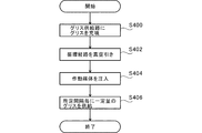
図5は、第1の実施形態におけるグリス供給方法のフローチャートである。図6は、第1の実施形態におけるグリス供給方法を説明する図である。図5および図6(a)に示すように、第1の実施形態におけるグリス供給方法では、廃熱発電装置100の作動前であって、循環経路204に作動媒体が封入される前に、グリス供給装置110からグリス供給路202にグリスGRが充填される(S400)。なお、ここでは、グリスガン等によりグリス供給路202にグリスGRを充填させるようにしてもよい。
FIG. 5 is a flowchart of the grease supply method according to the first embodiment. FIG. 6 is a diagram for explaining a grease supply method according to the first embodiment. As shown in FIG. 5 and FIG. 6A, in the grease supply method in the first embodiment, before the waste heat
その後、図6(b)に示すように、真空ポンプ114が作動され、ケーシング140および循環経路204が真空引きされる(S402)。このとき、廃熱発電装置100では、ケーシング140と密閉容器110aとが連通管116により連通されているので、ケーシング140および循環経路204と、密閉容器110aの圧力がほぼ等しくなる。したがって、廃熱発電装置100では、真空ポンプ114により真空引きされた際に、グリス供給路202の両端に圧力差が発生しないので、グリス供給路202内のグリスGRがケーシング140内に引き込まれることがなく、また、ピストン172がバルブ186側に移動してコンロッド174と離隔することもない。すなわち、本実施の形態では、調整手段の一例である連通管116が、循環経路204またはケーシング140の圧力と、密閉容器110aの圧力とを調整するため、グリスGRがケーシング140に引き込まれることを抑止できる。より好ましくは、調整手段が、ケーシング140または循環経路204の圧力と、密閉容器110aの圧力が略等しくなるように、これらの圧力を調整する。
Thereafter, as shown in FIG. 6B, the
その後、廃熱発電装置100では、外部から循環経路204に作動媒体が注入される(S404)。ここまでの工程(S400〜S404)が廃熱発電装置100の作動前に行われる。
Thereafter, in the waste heat
その後、廃熱発電装置100の作動が開始されると、グリス供給装置110が、所定間隔毎に一定量のグリスGRを、グリス供給路202を介して軸受138に供給する(S406)。
Thereafter, when the operation of the waste heat
このように、廃熱発電装置100では、ケーシング140と密閉容器110aとを連通管116により連通させることで、真空ポンプ114により真空引きされても、グリス供給路202の両端に圧力差が発生することがない。したがって、従来の廃熱発電装置300のようにグリスGRがケーシング140内に引き込まれることがなく、また、ピストン172がバルブ186側に移動してコンロッド174と離隔することもない。これにより、廃熱発電装置100では、作動中に、グリス供給装置110から軸受138にグリスGRが所定間隔毎に一定量供給されることになるので、グリスGRの不足による軸受138の発熱、破損を防止することができる。かくして、廃熱発電装置100では、グリスGRを軸受138に適切に供給することができる。
As described above, in the waste heat
<第2の実施形態>
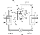
図7は、第2の実施形態における廃熱発電装置500の全体構成を示す概略図である。図7に示すように、廃熱発電装置500は、第1の実施形態における廃熱発電装置100と比較して、連通管116の代わりに真空ポンプ502が設けられている点で異なるが、その他の構成は実質的に等しく、実質的に等しい構成については同一符号を付し、その説明は省略する。
<Second Embodiment>
FIG. 7 is a schematic diagram illustrating an overall configuration of the waste heat
真空ポンプ502は、密閉容器110aに連通されており、駆動することで密閉容器110aを真空引きする。
The
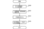
図8は、第2の実施形態におけるグリス供給方法のフローチャートである。図9は、第2の実施形態におけるグリス供給方法を説明する図である。図8および図9(a)に示すように、第2の実施形態におけるグリス供給方法では、廃熱発電装置500の作動前であって、循環経路204に作動媒体が封入される前に、グリス供給装置110からグリス供給路202にグリスGRが充填される(S600)。その後、図9(b)に示すように、真空ポンプ114、502が作動され、ケーシング140および循環経路204と、密閉容器110aとがそれぞれ真空引きされる(S602)。このとき、真空ポンプ502は、グリス供給路202の両端に圧力差が発生しないように、循環経路204の圧力に対して密閉容器110aの圧力を予め設定された所定の圧力差内に維持した状態で真空引きする。これにより、廃熱発電装置500では、真空ポンプ114、502により真空引きされた際に、グリス供給路202の両端に所定の圧力差以上の圧力差が発生しないので、グリス供給路202内のグリスGRがケーシング140内に引き込まれることがなく、また、ピストン172がバルブ186側に移動してコンロッド174と離隔することもない。すなわち、本実施の形態では、調整手段の一例である真空ポンプ502が、循環経路204またはケーシング140の圧力と、密閉容器110aの圧力とを調整するため、グリスGRがケーシング140に引き込まれることを抑止できる。より好ましくは、調整手段が、グリス供給路202の両端に圧力差が発生しないように循環経路204またはケーシング140の圧力と、密閉容器110aの圧力とを調整する。
FIG. 8 is a flowchart of the grease supply method according to the second embodiment. FIG. 9 is a diagram illustrating a grease supply method according to the second embodiment. As shown in FIGS. 8 and 9A, in the grease supply method according to the second embodiment, before the waste heat
その後、廃熱発電装置500では、外部から循環経路204に作動媒体が注入される(S604)。ここまでの工程(S600〜S604)が廃熱発電装置500の作動前に行われる。
Thereafter, in the waste heat
その後、廃熱発電装置500の作動が開始されると、グリス供給装置110が、所定間隔毎に一定量のグリスGRを、グリス供給路202を介して軸受138に供給する(S606)。
Thereafter, when the operation of the waste heat
このように、廃熱発電装置500では、ケーシング140および循環経路204を真空引きする真空ポンプ114と、密閉容器110aを真空引きする真空ポンプ502が設けられる。そして、廃熱発電装置500では、真空ポンプ114、502により、グリス供給路202の両端に所定の圧力差以上の圧力差が発生しないように、ケーシング140および循環経路204と、密閉容器110aとが真空引きされる。したがって、従来の廃熱発電装置300のようにグリスGRがケーシング140内に引き込まれることがなく、また、ピストン172がバルブ186側に移動してコンロッド174と離隔することもない。これにより、廃熱発電装置500では、作動中に、グリス供給装置110からグリスGRが所定間隔毎に一定量供給されることになるので、グリスGRの不足による軸受138の発熱、破損を防止することができる。かくして、廃熱発電装置500では、グリスGRを軸受138に適切に供給することができる。
As described above, the waste heat
以上、添付図面を参照しながら本発明の好適な実施形態について説明したが、本発明はかかる実施形態に限定されないことは言うまでもない。当業者であれば、特許請求の範囲に記載された範疇において、各種の変更例または修正例に想到し得ることは明らかであり、それらについても当然に本発明の技術的範囲に属するものと了解される。 As mentioned above, although preferred embodiment of this invention was described referring an accompanying drawing, it cannot be overemphasized that this invention is not limited to this embodiment. It will be apparent to those skilled in the art that various changes and modifications can be made within the scope of the claims, and these are naturally within the technical scope of the present invention. Is done.
なお、上記の実施形態では、密閉容器110aが、グリス供給装置110の各部を収容、密閉するようにしたが、密閉容器110aは、少なくとも、グリス供給路200、202にグリスを供給する部位であるシリンジ170を収容、密閉すればよい。
In the above embodiment, the sealed
また、上記の実施形態では、ケーシング140に真空ポンプ114が連通されるようにしたが、循環経路204に真空ポンプ114を連通するようにしてもよい。
In the above embodiment, the
また、上記の第1の実施形態では、ケーシング140と密閉容器110aとを連通管116で連通するようにしたが、循環経路204と密閉容器110aとを連通管116で連通するようにしてもよい。
In the first embodiment, the
本発明は、廃熱エネルギーを用いて発電を行う廃熱発電装置に利用することができる。 The present invention can be used in a waste heat power generation apparatus that generates power using waste heat energy.
100、500 廃熱発電装置
102 蒸発器
104 タービン発電機
110 グリス供給装置
110a 密閉容器
112 流路
114 真空ポンプ(第1の真空ポンプ)
116 連通管
130 インペラ
132 シャフト
134 発電機
136、138 軸受
140 ケーシング
200、202 グリス供給路
204 循環経路
502 真空ポンプ(第2の真空ポンプ)
100, 500 Waste heat
116
Claims (7)
前記循環経路に設けられ、ケーシング内に軸受を収容するタービン発電機と、
前記循環経路または前記ケーシングと連通する真空ポンプと、
前記軸受と接続されたグリス供給路と、
前記グリス供給路と接続され、密閉容器に収納されたグリス供給装置と、
前記循環経路または前記ケーシングの圧力と前記密閉容器の圧力の調整を行う調整手段と、
を有する廃熱発電装置。 A circulation path of the working medium;
A turbine generator provided in the circulation path and containing a bearing in the casing;
A vacuum pump communicating with the circulation path or the casing;
A grease supply path connected to the bearing;
A grease supply device connected to the grease supply path and housed in an airtight container;
Adjusting means for adjusting the pressure of the circulation path or the casing and the pressure of the sealed container;
Waste heat power generation device having.
前記調整手段は、前記密閉容器に連通する第2の真空ポンプである、請求項1に記載の廃熱発電装置。 The vacuum pump is a first vacuum pump;
The waste heat power generator according to claim 1, wherein the adjusting means is a second vacuum pump communicating with the sealed container.
前記インペラと一体回転するシャフトと、
前記シャフトの回転により発電する発電機と、
前記シャフトを回転自在に支持する軸受と、
前記循環経路の一部を構成するとともに前記インペラ、前記シャフト、前記発電機および前記軸受が収納されるケーシングと、
前記軸受にグリスを供給するグリス供給装置と、
前記グリス供給装置の少なくともグリスを供給する部位を密閉する密閉容器と、
前記グリス供給装置から前記軸受にグリスを供給するためのグリス供給路と、
前記循環経路または前記ケーシングに連通され、前記循環経路に前記作動媒体が封入される前に、該循環経路を真空引きする真空ポンプと、
前記循環経路または前記ケーシングと、前記密閉容器とを連通させる連通管と
を有する廃熱発電装置。 An impeller provided on a circulation path through which the working medium circulates, and rotated by the working medium vaporized by a heat source supplied from the outside by an evaporator provided on the circulation path;
A shaft that rotates integrally with the impeller;
A generator for generating electricity by rotating the shaft;
A bearing that rotatably supports the shaft;
A casing that constitutes a part of the circulation path and that houses the impeller, the shaft, the generator, and the bearing;
A grease supply device for supplying grease to the bearing;
A sealed container that seals at least a portion of the grease supply device that supplies grease;
A grease supply path for supplying grease to the bearing from the grease supply device;
A vacuum pump communicating with the circulation path or the casing and evacuating the circulation path before the working medium is sealed in the circulation path;
A waste heat power generation apparatus having a communication pipe for communicating the circulation path or the casing and the sealed container.
前記インペラと一体回転するシャフトと、
前記シャフトの回転により発電する発電機と、
前記シャフトを回転自在に支持する軸受と、
前記循環経路の一部を構成するとともに前記インペラ、前記シャフト、前記発電機および前記軸受が収納されるケーシングと、
前記軸受にグリスを供給するグリス供給装置と、
前記グリス供給装置の少なくともグリスを供給する部位を密閉する密閉容器と、
前記グリス供給装置から前記軸受にグリスを供給するためのグリス供給路と、
前記循環経路または前記ケーシングに連通され、該循環経路に前記作動媒体が封入される前に、該循環経路を真空引きする第1の真空ポンプと、
前記密閉容器に連通され、前記第1の真空ポンプにより前記循環経路が真空引きされる際に、該循環経路の圧力に対して該密閉容器内の圧力を所定の圧力差内に維持した状態で、該密閉容器内を真空引きする第2の真空ポンプと
を有する廃熱発電装置。 An impeller provided on a circulation path through which the working medium circulates, and rotated by the working medium vaporized by a heat source supplied from the outside by an evaporator provided on the circulation path;
A shaft that rotates integrally with the impeller;
A generator for generating electricity by rotating the shaft;
A bearing that rotatably supports the shaft;
A casing that constitutes a part of the circulation path and that houses the impeller, the shaft, the generator, and the bearing;
A grease supply device for supplying grease to the bearing;
A sealed container that seals at least a portion of the grease supply device that supplies grease;
A grease supply path for supplying grease to the bearing from the grease supply device;
A first vacuum pump that communicates with the circulation path or the casing and evacuates the circulation path before the working medium is sealed in the circulation path;
When the circulation path is evacuated by the first vacuum pump, the pressure in the sealed container is maintained within a predetermined pressure difference with respect to the pressure of the circulation path. A waste heat power generation apparatus comprising: a second vacuum pump that evacuates the sealed container.
Priority Applications (1)
| Application Number | Priority Date | Filing Date | Title |
|---|---|---|---|
| JP2014190326A JP2016061237A (en) | 2014-09-18 | 2014-09-18 | Waste-heat power generating apparatus |
Applications Claiming Priority (1)
| Application Number | Priority Date | Filing Date | Title |
|---|---|---|---|
| JP2014190326A JP2016061237A (en) | 2014-09-18 | 2014-09-18 | Waste-heat power generating apparatus |
Publications (1)
| Publication Number | Publication Date |
|---|---|
| JP2016061237A true JP2016061237A (en) | 2016-04-25 |
Family
ID=55797303
Family Applications (1)
| Application Number | Title | Priority Date | Filing Date |
|---|---|---|---|
| JP2014190326A Pending JP2016061237A (en) | 2014-09-18 | 2014-09-18 | Waste-heat power generating apparatus |
Country Status (1)
| Country | Link |
|---|---|
| JP (1) | JP2016061237A (en) |
Citations (10)
| Publication number | Priority date | Publication date | Assignee | Title |
|---|---|---|---|---|
| JPS57191403A (en) * | 1981-05-19 | 1982-11-25 | Hitachi Ltd | Method and device for lubricating turbine |
| JPS608596U (en) * | 1983-06-30 | 1985-01-21 | 株式会社島津製作所 | Grease supply device for vacuum pump lubrication |
| JP2010164043A (en) * | 2008-11-20 | 2010-07-29 | Kawasaki Heavy Ind Ltd | Exhaust heat recovery turbine system |
| US20120132287A1 (en) * | 2010-11-25 | 2012-05-31 | Aktiebolaget Skf | Pump for conveying a medium and lubricating system containing the same |
| JP2012149708A (en) * | 2011-01-19 | 2012-08-09 | Toshiba Corp | Device for circulating insulation material, and stationary induction electric apparatus |
| JP2013007367A (en) * | 2011-06-27 | 2013-01-10 | Ihi Corp | Waste-heat power generation apparatus, and power generating apparatus |
| JP2013032725A (en) * | 2011-08-01 | 2013-02-14 | Ihi Corp | Generator |
| JP2014001667A (en) * | 2012-06-18 | 2014-01-09 | Nippon Soken Inc | Rankine cycle device |
| JP5447677B2 (en) * | 2010-09-01 | 2014-03-19 | 株式会社Ihi | Waste heat power generator |
| JP2014129800A (en) * | 2012-12-28 | 2014-07-10 | Mitsubishi Heavy Ind Ltd | Power generating system, and maintenance method of power generating system |
-
2014
- 2014-09-18 JP JP2014190326A patent/JP2016061237A/en active Pending
Patent Citations (10)
| Publication number | Priority date | Publication date | Assignee | Title |
|---|---|---|---|---|
| JPS57191403A (en) * | 1981-05-19 | 1982-11-25 | Hitachi Ltd | Method and device for lubricating turbine |
| JPS608596U (en) * | 1983-06-30 | 1985-01-21 | 株式会社島津製作所 | Grease supply device for vacuum pump lubrication |
| JP2010164043A (en) * | 2008-11-20 | 2010-07-29 | Kawasaki Heavy Ind Ltd | Exhaust heat recovery turbine system |
| JP5447677B2 (en) * | 2010-09-01 | 2014-03-19 | 株式会社Ihi | Waste heat power generator |
| US20120132287A1 (en) * | 2010-11-25 | 2012-05-31 | Aktiebolaget Skf | Pump for conveying a medium and lubricating system containing the same |
| JP2012149708A (en) * | 2011-01-19 | 2012-08-09 | Toshiba Corp | Device for circulating insulation material, and stationary induction electric apparatus |
| JP2013007367A (en) * | 2011-06-27 | 2013-01-10 | Ihi Corp | Waste-heat power generation apparatus, and power generating apparatus |
| JP2013032725A (en) * | 2011-08-01 | 2013-02-14 | Ihi Corp | Generator |
| JP2014001667A (en) * | 2012-06-18 | 2014-01-09 | Nippon Soken Inc | Rankine cycle device |
| JP2014129800A (en) * | 2012-12-28 | 2014-07-10 | Mitsubishi Heavy Ind Ltd | Power generating system, and maintenance method of power generating system |
Similar Documents
| Publication | Publication Date | Title |
|---|---|---|
| EP3193434B1 (en) | Compact high speed generator | |
| JP5866819B2 (en) | Waste heat generator | |
| JP2013169029A (en) | Power generator | |
| JP4286062B2 (en) | Power generation apparatus and power generation method | |
| JP5447677B2 (en) | Waste heat power generator | |
| JP5834538B2 (en) | Waste heat generator | |
| WO2015083458A1 (en) | Coolant pump and binary power generation system using such coolant pump | |
| CN102733873B (en) | Power generation system | |
| JP5397998B2 (en) | Shaft seal structure of vapor compressor for vacuum concentrator | |
| JP6288486B1 (en) | Steam turbine system and method for starting steam turbine | |
| JP2016061237A (en) | Waste-heat power generating apparatus | |
| JP5796371B2 (en) | Waste heat power generator and power generator | |
| JP2008175212A (en) | Turbine generator | |
| JP6339908B2 (en) | Grease supply method | |
| JP2006009592A (en) | Generating set and its operating method | |
| US20160177955A1 (en) | Compression system | |
| JP2014105647A (en) | Turbine generator and waste heat generator | |
| KR101563629B1 (en) | Generating system for organic rankine cycle | |
| JP7391196B2 (en) | an integrated motor-compressor unit having a cooling circuit and a pressure reduction system configured to reduce the pressure of the cooling fluid; | |
| KR101946079B1 (en) | Super conducting synchronous machine comprising a rotor which can rotate in relation to a stator and which has at least one super conducting winding | |
| KR101187727B1 (en) | Organic fluid turbine generator preventing penetration of operating fluid | |
| JP2006509953A (en) | Vacuum pump discharge device and operating method thereof | |
| KR101938138B1 (en) | Generating cycle system | |
| JP2010178486A (en) | Superconducting rotating electric machine | |
| JP2013057265A (en) | Power generation equipment |
Legal Events
| Date | Code | Title | Description |
|---|---|---|---|
| A621 | Written request for application examination |
Free format text: JAPANESE INTERMEDIATE CODE: A621 Effective date: 20170720 |
|
| A711 | Notification of change in applicant |
Free format text: JAPANESE INTERMEDIATE CODE: A712 Effective date: 20171206 |
|
| RD02 | Notification of acceptance of power of attorney |
Free format text: JAPANESE INTERMEDIATE CODE: A7422 Effective date: 20171228 |
|
| A977 | Report on retrieval |
Free format text: JAPANESE INTERMEDIATE CODE: A971007 Effective date: 20180515 |
|
| A131 | Notification of reasons for refusal |
Free format text: JAPANESE INTERMEDIATE CODE: A131 Effective date: 20180522 |
|
| A02 | Decision of refusal |
Free format text: JAPANESE INTERMEDIATE CODE: A02 Effective date: 20181127 |