JP2016100928A - 駆動装置 - Google Patents
駆動装置 Download PDFInfo
- Publication number
- JP2016100928A JP2016100928A JP2014234105A JP2014234105A JP2016100928A JP 2016100928 A JP2016100928 A JP 2016100928A JP 2014234105 A JP2014234105 A JP 2014234105A JP 2014234105 A JP2014234105 A JP 2014234105A JP 2016100928 A JP2016100928 A JP 2016100928A
- Authority
- JP
- Japan
- Prior art keywords
- flexible substrate
- diaphragm
- fixed
- piezoelectric element
- holding member
- Prior art date
- Legal status (The legal status is an assumption and is not a legal conclusion. Google has not performed a legal analysis and makes no representation as to the accuracy of the status listed.)
- Granted
Links
Images


Classifications
-
- H—ELECTRICITY
- H02—GENERATION; CONVERSION OR DISTRIBUTION OF ELECTRIC POWER
- H02N—ELECTRIC MACHINES NOT OTHERWISE PROVIDED FOR
- H02N2/00—Electric machines in general using piezoelectric effect, electrostriction or magnetostriction
- H02N2/02—Electric machines in general using piezoelectric effect, electrostriction or magnetostriction producing linear motion, e.g. actuators; Linear positioners ; Linear motors
- H02N2/026—Electric machines in general using piezoelectric effect, electrostriction or magnetostriction producing linear motion, e.g. actuators; Linear positioners ; Linear motors by pressing one or more vibrators against the driven body
-
- H—ELECTRICITY
- H02—GENERATION; CONVERSION OR DISTRIBUTION OF ELECTRIC POWER
- H02N—ELECTRIC MACHINES NOT OTHERWISE PROVIDED FOR
- H02N2/00—Electric machines in general using piezoelectric effect, electrostriction or magnetostriction
- H02N2/0005—Electric machines in general using piezoelectric effect, electrostriction or magnetostriction producing non-specific motion; Details common to machines covered by H02N2/02 - H02N2/16
- H02N2/001—Driving devices, e.g. vibrators
- H02N2/0015—Driving devices, e.g. vibrators using only bending modes
-
- H—ELECTRICITY
- H02—GENERATION; CONVERSION OR DISTRIBUTION OF ELECTRIC POWER
- H02N—ELECTRIC MACHINES NOT OTHERWISE PROVIDED FOR
- H02N2/00—Electric machines in general using piezoelectric effect, electrostriction or magnetostriction
- H02N2/0005—Electric machines in general using piezoelectric effect, electrostriction or magnetostriction producing non-specific motion; Details common to machines covered by H02N2/02 - H02N2/16
- H02N2/0075—Electrical details, e.g. drive or control circuits or methods
- H02N2/0085—Leads; Wiring arrangements
Landscapes
- General Electrical Machinery Utilizing Piezoelectricity, Electrostriction Or Magnetostriction (AREA)
Abstract
【解決手段】駆動装置のフレキシブル基板3は、圧電素子2に固定される第1の固定部A1と、保持部材5に固定される第2の固定部A2と、振動板1の移動に伴い屈曲変形する屈曲部3fと、を備え、第2の固定部A2は第1の固定部A1と屈曲部3fとの間に設けられる。
【選択図】図10
Description
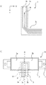
本発明の超音波モータの基本的な構成を図1により説明する。図1(a)は平面図、図1(b)は正面図、図1(c)、(d)は側面図、図1(e)は底面図である。図1において振動板1は、矩形状の平板部と、平板部に設けられた突起部1a及び1bとを有する。突起部1a及び1bは、絞り加工により平板部と一体成型してもよいし、別部材を平板部に接着により固定してもよい。振動板1には高周波振動する圧電素子2が固定されている。圧電素子2は、同方向に分極された2箇所の領域2aと2bとを備え、領域2aがα相に、領域2bがβ相に割り当てられている。圧電素子2は、更に分極されていない領域2cを備えており、領域2cは、図1(b)における圧電素子2の裏面2eの全面電極から側面の2dの領域の電極を経由して導通されたグランドとして使用する電極である。
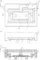
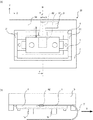
次に、超音波モータの従来例について説明する。図7及び図8は、いずれも従来例における、フレキシブル基板3が変形するという課題を示している。図7(a)は駆動部20の平面図、図7(b)は駆動部20の底面図である。図7(a)では、第2の保持部材5及びローラ61の記載が省略されている。図8(a)はリニア駆動装置30の正面図、図8(b)は図8(a)の断面線b−bにおける断面図である。
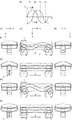
次に、第1の実施形態について、図10を用いて説明する。図10(a)は、第1の実施形態に係るフレキシブル基板3の固定方法を示す底面図、図10(b)は正面図である。主要な構成は、図4に示した構成と同じである。フレキシブル基板3は、両面粘着テープ等の接着手段により第2の保持部材5の固定面5a上に第2の固定部A2で固定されている。このとき、フレキシブル基板3は、圧電素子2上の第1の固定部A1から延出する方向の延長線上(N)で第2の保持部材5に固定されている。すなわち、第2の固定部A2は、フレキシブル基板3が第1の固定部A1から延出する方向の延長線上(N)に設けられている。フレキシブル基板3は、第2の固定部A2で固定された後、移動方向のX方向へ延出している。なお、図10(a)に示す延長線Nの位置は、長辺方向の曲げ振動の2次の固有振動モードの節の位置でもある。

以下、本発明の第2の実施形態について、図13を用いて説明する。第1の実施形態では、フレキシブル基板3が両面粘着テープにより第2の保持部材5に固定されている。しかしながら、第2の実施形態では、フレキシブル基板3が第2の保持部材5に対してX方向及びZ方向の移動は規制され、Y方向の移動は規制されないように第2の保持部材5に固定されている。なお、第1の実施形態と同一部材のものは同一記号で図示される。また、第1の実施形態と同じところは説明を省略し、第1の実施形態と異なるところだけを説明する。
以下、本発明の第3の実施形態について図16を用いて説明する。第3の実施形態では、フレキシブル基板3が第1の保持部材4に固定されている点が第1の実施形態とは異なっている。なお、第1の実施形態と同一部材のものは、同一記号で図示される。また、第1の実施形態と同じところは説明を省略し、第1の実施形態と異なるところだけを説明する。
1a、1b 突起部
1c、1d 連結部
1e、1f 固定穴
2 圧電素子
2a、2b、2c 領域
2d 側面の領域
2e 裏面
3 フレキシブル基板
3a、3b、3c 電極
3d ベース基板
3e 固定穴
3f 屈曲部
4 第1の保持部材
4a、4b 固定軸
4c 切り欠き部
4d 第1の保持部材4側ローラ受け面
4e 固定面
5 第2の保持部材
5a 固定面
5b 第2の保持部材5側ローラ受け面
5c 固定ボス
5d 固定爪
61 ローラ
62 加圧ばね
7 摩擦部材
71 ベース部材
71a 底面
71b 固定ボス
72 転動コロ
10 超音波モータ
20 駆動部
30 リニア駆動装置
A1 第1の固定部
A2 第2の固定部
Claims (8)
- 略矩形状の平板部と前記平板部の上に設けられた突起部とを有する振動板と、
前記振動板に固定され高周波振動する圧電素子と、
該圧電素子に固定され該圧電素子に給電するためのフレキシブル基板と、
前記振動板を保持するための保持部材と、
前記振動板を付勢するための加圧部材と、
前記振動板が加圧部材により付勢され当接する摩擦部材と、
を有し、
前記振動板は、前記圧電素子の高周波振動により前記摩擦部材に対して移動し、
前記フレキシブル基板は、前記圧電素子に固定される第1の固定部と、前記保持部材に固定される第2の固定部と、前記振動板の移動に伴い屈曲変形する屈曲部と、を備え、
前記第2の固定部は、前記第1の固定部と前記屈曲部との間に設けられていることを特徴とする駆動装置。 - 前記フレキシブル基板は、前記振動板の振動モードの節となる位置から引き出されていることを特徴とする、請求項1に記載の駆動装置。
- 前記保持部材は、前記振動板を保持するための第1の保持部材と、前記第1の保持部材を保持するための第2の保持部材と、に分かれており、
前記フレキシブル基板は、該第1の保持部材と該第2の保持部材のいずれかに固定されていることを特徴とする、請求項1又は2に記載の駆動装置。 - 前記第2の固定部は、前記フレキシブル基板が前記第1の固定部から延出する方向の延長線上に設けられていることを特徴とする、請求項1乃至3のいずれか1項に記載の駆動装置。
- 前記フレキシブル基板が前記第1の固定部から延出する方向は、前記振動板の移動方向及び前記振動板の加圧方向に直交する方向であることを特徴とする、請求項1乃至4のいずれか1項に記載の駆動装置。
- 前記フレキシブル基板は、前記振動板の移動方向及び前記振動板の加圧方向の移動が規制され、前記移動方向と前記加圧方向と直交する方向の移動が規制されないように、前記第2の固定部で固定されていることを特徴とする、請求項1乃至5のいずれか1項に記載の駆動装置。
- 前記圧電素子に発生させる高周波振動の周波数は、前記フレキシブル基板のうち、前記第1の固定部と前記第2の固定部との間の該フレキシブル基板の固有振動モードの共振周波数と異なることを特徴とする、請求項1乃至6のいずれか1項に記載の駆動装置。
- 前記駆動装置は、超音波モータであることを特徴とする、請求項1乃至7のいずれか1項に記載の駆動装置。
Priority Applications (2)
| Application Number | Priority Date | Filing Date | Title |
|---|---|---|---|
| JP2014234105A JP6463951B2 (ja) | 2014-11-19 | 2014-11-19 | 駆動装置 |
| US14/937,283 US10103650B2 (en) | 2014-11-19 | 2015-11-10 | Driving device |
Applications Claiming Priority (1)
| Application Number | Priority Date | Filing Date | Title |
|---|---|---|---|
| JP2014234105A JP6463951B2 (ja) | 2014-11-19 | 2014-11-19 | 駆動装置 |
Publications (2)
| Publication Number | Publication Date |
|---|---|
| JP2016100928A true JP2016100928A (ja) | 2016-05-30 |
| JP6463951B2 JP6463951B2 (ja) | 2019-02-06 |
Family
ID=55962601
Family Applications (1)
| Application Number | Title | Priority Date | Filing Date |
|---|---|---|---|
| JP2014234105A Active JP6463951B2 (ja) | 2014-11-19 | 2014-11-19 | 駆動装置 |
Country Status (2)
| Country | Link |
|---|---|
| US (1) | US10103650B2 (ja) |
| JP (1) | JP6463951B2 (ja) |
Cited By (4)
| Publication number | Priority date | Publication date | Assignee | Title |
|---|---|---|---|---|
| JP2017225294A (ja) * | 2016-06-17 | 2017-12-21 | ミネベアミツミ株式会社 | 回転装置及びその回転装置を備える空調システムを有する乗り物 |
| JP2019221073A (ja) * | 2018-06-20 | 2019-12-26 | キヤノン株式会社 | 振動波モータ及び駆動装置 |
| JP2020005353A (ja) * | 2018-06-26 | 2020-01-09 | キヤノン株式会社 | 振動波モータ及び振動波モータを用いた駆動装置 |
| JP2020137237A (ja) * | 2019-02-19 | 2020-08-31 | キヤノン株式会社 | 振動波モータおよび振動波モータを備えた鏡筒駆動装置 |
Families Citing this family (4)
| Publication number | Priority date | Publication date | Assignee | Title |
|---|---|---|---|---|
| JP6829555B2 (ja) | 2016-06-23 | 2021-02-10 | キヤノン株式会社 | 振動波モータ及びレンズ駆動装置 |
| JP6605012B2 (ja) | 2017-12-08 | 2019-11-13 | キヤノン株式会社 | 振動波モータ及び振動波モータを用いたレンズ駆動装置 |
| JP2019195233A (ja) | 2018-05-01 | 2019-11-07 | キヤノン株式会社 | 振動波モータ及び振動波モータを用いた駆動装置 |
| JP7112250B2 (ja) | 2018-05-24 | 2022-08-03 | キヤノン株式会社 | 振動波モータ及び駆動装置 |
Citations (2)
| Publication number | Priority date | Publication date | Assignee | Title |
|---|---|---|---|---|
| JP2006081006A (ja) * | 2004-09-10 | 2006-03-23 | Konica Minolta Photo Imaging Inc | 振れ補正機構付きカメラ |
| JP2012227988A (ja) * | 2011-04-15 | 2012-11-15 | Canon Inc | 振動型リニアアクチュエータとそれを有する光学機器 |
Family Cites Families (7)
| Publication number | Priority date | Publication date | Assignee | Title |
|---|---|---|---|---|
| JP4331531B2 (ja) | 2003-08-06 | 2009-09-16 | オリンパス株式会社 | 振動波リニアモータ及びそれを用いたレンズ装置 |
| JP4276914B2 (ja) * | 2003-09-18 | 2009-06-10 | オリンパス株式会社 | 振動波リニアモータ及びその駆動方法 |
| US7969065B2 (en) * | 2008-09-09 | 2011-06-28 | Canon Kabushiki Kaisha | Vibration wave driving device |
| JP2011045208A (ja) * | 2009-08-24 | 2011-03-03 | Olympus Corp | 超音波モータ |
| JP5467821B2 (ja) * | 2009-09-07 | 2014-04-09 | パナソニック株式会社 | 振動型アクチュエータ |
| JP2012044832A (ja) * | 2010-08-23 | 2012-03-01 | Canon Inc | 振動波駆動装置及び画像振れ補正装置 |
| CN103636017B (zh) * | 2011-06-27 | 2016-06-01 | 佳能株式会社 | 压电元件、振荡波电机和光学装置 |
-
2014
- 2014-11-19 JP JP2014234105A patent/JP6463951B2/ja active Active
-
2015
- 2015-11-10 US US14/937,283 patent/US10103650B2/en active Active
Patent Citations (2)
| Publication number | Priority date | Publication date | Assignee | Title |
|---|---|---|---|---|
| JP2006081006A (ja) * | 2004-09-10 | 2006-03-23 | Konica Minolta Photo Imaging Inc | 振れ補正機構付きカメラ |
| JP2012227988A (ja) * | 2011-04-15 | 2012-11-15 | Canon Inc | 振動型リニアアクチュエータとそれを有する光学機器 |
Cited By (10)
| Publication number | Priority date | Publication date | Assignee | Title |
|---|---|---|---|---|
| JP2017225294A (ja) * | 2016-06-17 | 2017-12-21 | ミネベアミツミ株式会社 | 回転装置及びその回転装置を備える空調システムを有する乗り物 |
| US10770951B2 (en) | 2016-06-17 | 2020-09-08 | Minebea Mitsumi Inc. | Rotary apparatus and vehicle having air conditioning system including the rotating apparatus |
| US11689078B2 (en) | 2016-06-17 | 2023-06-27 | Minebea Mitsumi Inc. | Rotary apparatus and vehicle having air conditioning system including the rotating apparatus |
| US12057758B2 (en) | 2016-06-17 | 2024-08-06 | Minebea Mitsumi Inc. | Rotary apparatus and vehicle having air conditioning system including the rotating apparatus |
| JP2019221073A (ja) * | 2018-06-20 | 2019-12-26 | キヤノン株式会社 | 振動波モータ及び駆動装置 |
| US11245343B2 (en) | 2018-06-20 | 2022-02-08 | Canon Kabushiki Kaisha | Vibration wave motor and driving device |
| JP7094792B2 (ja) | 2018-06-20 | 2022-07-04 | キヤノン株式会社 | 振動波モータ及び駆動装置 |
| JP2020005353A (ja) * | 2018-06-26 | 2020-01-09 | キヤノン株式会社 | 振動波モータ及び振動波モータを用いた駆動装置 |
| JP7098438B2 (ja) | 2018-06-26 | 2022-07-11 | キヤノン株式会社 | 振動波モータ及び振動波モータを用いた駆動装置 |
| JP2020137237A (ja) * | 2019-02-19 | 2020-08-31 | キヤノン株式会社 | 振動波モータおよび振動波モータを備えた鏡筒駆動装置 |
Also Published As
| Publication number | Publication date |
|---|---|
| JP6463951B2 (ja) | 2019-02-06 |
| US10103650B2 (en) | 2018-10-16 |
| US20160141979A1 (en) | 2016-05-19 |
Similar Documents
| Publication | Publication Date | Title |
|---|---|---|
| JP6463951B2 (ja) | 駆動装置 | |
| US10171008B2 (en) | Vibration wave motor and driving apparatus using the vibration wave motor | |
| JP5765993B2 (ja) | 振動型駆動装置 | |
| US11063205B2 (en) | Vibration actuator and method for manufacturing the same | |
| CN101726825A (zh) | 透镜驱动单元以及包括该透镜驱动单元的相机模块 | |
| JP2014018027A (ja) | 振動型アクチュエータ、撮像装置、及びステージ | |
| JP2009017735A (ja) | 超音波モータ | |
| JP2015080329A (ja) | 振動型駆動装置の振動子、振動型駆動装置、交換レンズ、撮像装置、自動ステージ | |
| JP2016226129A (ja) | 振動波モータ | |
| JP6422248B2 (ja) | 駆動装置及びそれを有するレンズ駆動装置 | |
| JP6381326B2 (ja) | 超音波モータ | |
| JP2016027780A (ja) | 振動型アクチュエータ、レンズ鏡筒、撮像装置及び自動ステージ | |
| JP6576214B2 (ja) | 振動型アクチュエータ、レンズ鏡筒、撮像装置及びステージ装置 | |
| US10924037B2 (en) | Vibration motor that prevents resonance of contact member, and electronic apparatus | |
| JP6765849B2 (ja) | 振動型アクチュエータ及び電子機器 | |
| JP6649729B2 (ja) | 振動波モータ | |
| JP2016032351A (ja) | 振動型アクチュエータ、光学機器、及び撮像装置 | |
| JP6708472B2 (ja) | 振動波モータ及び振動波モータが搭載された光学機器 | |
| JP6639244B2 (ja) | 振動型アクチュエータ及び電子機器 | |
| CN107947626B (zh) | 使用振子的马达以及电子设备 | |
| JP4554261B2 (ja) | 駆動装置 | |
| JP6774222B2 (ja) | 振動波モータ及び振動波モータを用いた光学装置 | |
| JP2022057781A (ja) | 振動型駆動装置およびこれを備えた装置 | |
| JP6273137B2 (ja) | モータ、及びモータ付き装置 | |
| JP2018101094A (ja) | 振動型アクチュエータ、レンズ駆動装置、光学機器及び電子機器 |
Legal Events
| Date | Code | Title | Description |
|---|---|---|---|
| A621 | Written request for application examination |
Free format text: JAPANESE INTERMEDIATE CODE: A621 Effective date: 20171106 |
|
| RD05 | Notification of revocation of power of attorney |
Free format text: JAPANESE INTERMEDIATE CODE: A7425 Effective date: 20171214 |
|
| RD04 | Notification of resignation of power of attorney |
Free format text: JAPANESE INTERMEDIATE CODE: A7424 Effective date: 20180126 |
|
| A977 | Report on retrieval |
Free format text: JAPANESE INTERMEDIATE CODE: A971007 Effective date: 20180808 |
|
| A131 | Notification of reasons for refusal |
Free format text: JAPANESE INTERMEDIATE CODE: A131 Effective date: 20180828 |
|
| A521 | Request for written amendment filed |
Free format text: JAPANESE INTERMEDIATE CODE: A523 Effective date: 20181022 |
|
| TRDD | Decision of grant or rejection written | ||
| A01 | Written decision to grant a patent or to grant a registration (utility model) |
Free format text: JAPANESE INTERMEDIATE CODE: A01 Effective date: 20181206 |
|
| A61 | First payment of annual fees (during grant procedure) |
Free format text: JAPANESE INTERMEDIATE CODE: A61 Effective date: 20190107 |
|
| R151 | Written notification of patent or utility model registration |
Ref document number: 6463951 Country of ref document: JP Free format text: JAPANESE INTERMEDIATE CODE: R151 |