JP2016101856A - Combination structure of vehicular storage box and lighting device - Google Patents
Combination structure of vehicular storage box and lighting device Download PDFInfo
- Publication number
- JP2016101856A JP2016101856A JP2014241482A JP2014241482A JP2016101856A JP 2016101856 A JP2016101856 A JP 2016101856A JP 2014241482 A JP2014241482 A JP 2014241482A JP 2014241482 A JP2014241482 A JP 2014241482A JP 2016101856 A JP2016101856 A JP 2016101856A
- Authority
- JP
- Japan
- Prior art keywords
- light
- light source
- storage box
- guide member
- light guide
- Prior art date
- Legal status (The legal status is an assumption and is not a legal conclusion. Google has not performed a legal analysis and makes no representation as to the accuracy of the status listed.)
- Granted
Links
Images



Landscapes
- Vehicle Step Arrangements And Article Storage (AREA)
- Arrangements Of Lighting Devices For Vehicle Interiors, Mounting And Supporting Thereof, Circuits Therefore (AREA)
Abstract
【課題】収納ボックス内部の広範囲域を適切に照明し、かつ光源の嵩張りなどに起因して収納ボックスの取り付けに苦慮するといった不具合も好適に解消可能な構造を提供する。【解決手段】前面部が物品出し入れ用の開口部10aとされた物品収納空間部10を形成しており、かつ車室内に配設される収納ボックスBと、物品収納空間部10を照明するための光源3を有する照明装置Lと、を備えている構造であって、照明装置Lは、光源3が収納ボックスBの背面部に設けられ、かつ光源3から発せられた光が内部に入射することによって外面が発光する導光部材4を備えた構成とされ、導光部材4は、光源3から光を受ける位置から物品収納空間部10の壁部11eの位置まで延びている。【選択図】 図1The present invention provides a structure that can suitably illuminate a wide area inside a storage box and that can suitably solve problems such as difficulty in mounting the storage box due to the bulk of the light source. In order to illuminate a storage box B and an article storage space 10 disposed in a vehicle interior, the front portion forms an article storage space 10 having an opening 10a for putting in and out the goods. The illumination device L includes the light source 3, and the illumination device L includes the light source 3 provided on the back surface of the storage box B, and light emitted from the light source 3 is incident on the inside. Thus, the light guide member 4 whose outer surface emits light is provided, and the light guide member 4 extends from the position where light is received from the light source 3 to the position of the wall portion 11e of the article storage space 10. [Selection] Figure 1
Description
本発明は、車両用収納ボックスと照明装置との組み合わせ構造に関する。 The present invention relates to a combined structure of a vehicle storage box and a lighting device.
自動車などの車両の車室内には、小物類などを収納するための収納ボックスが設けられているのが一般的であるが、この収納ボックスの内部がよく見えるようにするための手段として、照明装置を付属して設ける手段がよく用いられる(たとえば、特許文献1などを参照)。
前記したような手段の一例としては、図6に示すように、物品収納空間部71が形成された収納ボックス7の上壁部70に、LED光源などの光源8を取り付ける手段が挙げられる。
A storage box for storing small items is generally provided in the interior of a vehicle such as an automobile. However, as a means for making the inside of the storage box visible, illumination is provided. A means for attaching the device is often used (for example, see Patent Document 1).
As an example of the above-described means, as shown in FIG. 6, there is a means for attaching a
しかしながら、前記従来の手段においては,次に述べるように、改善すべき余地がある。 However, the conventional means has room for improvement as described below.
第1に、光源8からの光の照射範囲角度βは、さほど大きくない。このため、収納ボックス7内の全域を明るく、かつ略均一な状態に照明することが困難である。その結果、たとえば大きなサイズの物品を物品収納空間部71内に収納させた際に、光源8の光の大半が前記物品によって遮られ、物品収納空間部71内の全体が暗くなるといった不具合を生じてしまう。
第2に、光源8が物品収納空間部71の内側に大きく突出しないように設定するには、光源8を上壁部70の上方に突出させる必要があり、その突出寸法Hが大きくなる。これでは、収納ボックス7を所定のスペースにその前面側から挿入させて取り付けるような場合に、前記スペースを形成するための部材95などに光源8が干渉(当接)し、収納ボックス7の取り付けに苦慮するといった不具合を生じる。
First, the irradiation range angle β of light from the
Secondly, in order to set the
本発明は、前記したような事情のもとで考え出されたものであり、収納ボックス内部の広い範囲を適切に照明することができ、しかも光源が嵩張るようなことに起因して収納ボックスの取り付けに苦慮するといった不具合も好適に解消することが可能な車両用収納ボックスと照明装置との組み合わせ構造を提供することを、その課題としている。 The present invention has been conceived under the circumstances as described above, and can appropriately illuminate a wide range inside the storage box, and the light source is bulky. It is an object of the present invention to provide a combined structure of a vehicle storage box and a lighting device that can suitably solve problems such as difficulty in mounting.
上記の課題を解決するため、本発明では、次の技術的手段を講じている。 In order to solve the above problems, the present invention takes the following technical means.
本発明により提供される車両用収納ボックスと照明装置との組み合わせ構造は、前面部が物品出し入れ用の開口部とされた物品収納空間部を形成しており、かつ車室内に配設される収納ボックスと、前記物品収納空間部を照明するための光源を有する照明装置と、を備えている、車両用収納ボックスと照明装置との組み合わせ構造であって、前記照明装置は、前記光源が前記収納ボックスの背面部に設けられ、かつ前記光源から発せられた光が内部に入射することによって外面が発光する導光部材を備えた構成とされており、前記導光部材は、前記光源から光を受ける位置から前記物品収納空間部の壁部の位置まで延びた
状態に設けられていることを特徴としている。
The combined structure of the vehicular storage box and the lighting device provided by the present invention forms an article storage space whose front portion is an opening for putting in and out the article, and is stored in the vehicle compartment. And a lighting device having a light source for illuminating the article storage space, the vehicle storage box and the lighting device, wherein the light source is stored in the lighting device. The light guide member is provided on the back surface of the box and has an outer surface that emits light when the light emitted from the light source enters the inside, and the light guide member emits light from the light source. It is provided in the state extended from the receiving position to the position of the wall part of the said article | item storage space part.
このような構成によれば、次のような効果が得られる。
第1に、導光部材を発光させる場合、LED光源などの光源をそのまま利用して照明を行なわせる場合と比較すると、光の照射範囲角度を広くとることが可能である。このため、導光部材から物品収納空間部内の全域などの広い領域にわたって光を略均一に照射することが可能となる。その結果、物品収納空間部内が見やすくなり、たとえばサイズが大きい物品を収納した場合であっても、光の多くが遮られて物品収納空間部内の全体が暗くなるといった不具合を適切に防止または抑制することができる。
第2に、光源は、収納ボックスの背面部に設けられており、前記従来技術とは異なり、物品収納空間部のたとえば上壁部の上方などに光源が大きく突出するようなことはない。一方、導光部材は、光源よりも小サイズ(小径あるいは小幅など)に形成することができ、導光部材を物品収納空間部の壁部に設けたとしても、この導光部材が前記壁部の外部に大きく突出して嵩張るようなことを回避することができる。このため、収納ボックスを所定のスペースにその前面側から挿入させて取り付けるような場合に、前記スペースを形成するための部材などに光源や導光部材が干渉するといった不具合を無くし、収納ボックスの取り付けの容易化を図ることができる。
According to such a configuration, the following effects can be obtained.
First, when the light guide member is caused to emit light, the light irradiation range angle can be made wider compared to the case where illumination is performed using a light source such as an LED light source as it is. For this reason, it becomes possible to irradiate light substantially uniformly over wide areas, such as the whole region in an article storage space part, from a light guide member. As a result, the inside of the article storage space becomes easy to see. For example, even when a large-sized article is stored, a problem that much of the light is blocked and the entire inside of the article storage space becomes dark is appropriately prevented or suppressed. be able to.
Secondly, the light source is provided on the back surface of the storage box, and unlike the prior art, the light source does not protrude greatly above the upper wall of the article storage space. On the other hand, the light guide member can be formed in a smaller size (small diameter or narrow width) than the light source, and even if the light guide member is provided on the wall portion of the article storage space portion, the light guide member is the wall portion. It is possible to avoid a large protrusion and bulky outside. For this reason, when the storage box is inserted into a predetermined space from the front side and attached, the trouble of the light source or the light guide member interfering with the member for forming the space is eliminated, and the storage box is attached. Can be facilitated.
本発明のその他の特徴および利点は、添付図面を参照して以下に行なう発明の実施の形態の説明から、より明らかになるであろう。 Other features and advantages of the present invention will become more apparent from the following description of embodiments of the present invention with reference to the accompanying drawings.
以下、本発明の好ましい実施の形態について、図面を参照して具体的に説明する。 Hereinafter, preferred embodiments of the present invention will be specifically described with reference to the drawings.
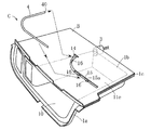
図1に示す構造Cは、収納ボックスBと、照明装置Lとを組み合わせた構造である。
収納ボックスBは、たとえば自動車のダッシュボードの車幅方向略中央部などに設けられた凹部または開口部分に差し込まれて取り付けられるものであり、全体が樹脂製であって、前面部が物品出し入れ用の開口部10aとされた物品収納空間部10を形成している。
The structure C shown in FIG. 1 is a structure in which the storage box B and the lighting device L are combined.
The storage box B is, for example, inserted into and attached to a recess or an opening provided in a substantially central part in the vehicle width direction of a dashboard of an automobile, and is entirely made of resin, and the front part is used for putting in and out articles. The
図2に示すように、収納ボックスBは、ヒンジ部1c(たとえば、インテグラルヒンジ部)を介して、ボックス本体部1aと上カバー部1bとが一体的に繋がった構成とされている。ボックス本体部1aは、底壁部11a、この底壁部11aから立ち上がった左右一対の側壁部11b,11c、および奥壁部11dを備えており、上カバー部1bを閉じることにより、上部が閉塞した物品収納空間部10が形成される。したがって、上カバー部1bの一部の領域は、物品収納空間部10の上壁部11eに相当する。なお、ボックス本体部1aと上カバー部1bとの位置決め、および上カバー部1bの閉じ状態保持を図るための手段として、上カバー部1bには、位置決め用突起20および係止用突起21が適当数設けられている。これに対応し、ボックス本体部1aには、位置決め用突起20が密に
嵌入する孔部20a、および係止用突起21を抜け止め状態に挿入係止させるための係止用孔部21aがそれぞれ適当数設けられている。
As shown in FIG. 2, the storage box B is configured such that the box body 1a and the
照明装置Lは、LED光源などの光源3と、導光部材4とを組み合わせて構成されている。光源3は、収納ボックスBの背面部に設けられている。好ましくは、光源3は、この光源3から発せられた光が物品収納空間部10内に直接進行しないように物品収納空間部10の外部に設けられている。図2に示すように、物品収納空間部10の側壁部11bの外側には、補助壁部12が設けられ、かつこの補助壁部12には、孔部13aが設けられた後壁部13が連設されている(図4(a)も参照)。光源3は、その発光部が孔部13aに挿入され、または発光部が孔部13aに対面するようにして後壁部13に取り付けられている。このことにより、光源3から発せられた光のうち、導光部材4に入射しない余剰の光は、図2で示した壁部11bと補助壁部12との相互間の領域に進行するようになっている。
The illumination device L is configured by combining a
導光部材4は、たとえば住友スリーエム株式会社製の商品名ライトストリングであり、可撓性を有し、かつコア部およびクラッド部(図示略)が同心状に形成されたファイバ状である。導光部材4は、その一端面40から内部に光が入射すると、この光を導光部材4の長手方向に進行させつつ、光の一部を導光部材4の外面から出射させ、導光部材4の外面全体が発光面となるように構成されたものである。この導光部材4の一端面40は、光源3に対面接近した配置とされている。
The
導光部材4は、光源3に対面接近した位置から物品収納空間部10の上壁部11eまで延びた状態に設けられている。より具体的には、上壁部11eには、導光部材4を上下方向に貫通させるための貫通孔14が設けられている。また、上壁部11eの上面部には、導光部材4を嵌入保持させるための凹溝15が設けられている(図3も参照)。この凹溝15の底部の全体または一部には、導光部材4の外面を物品収納空間部10側に臨ませて、導光部材4から発生せられた光を物品収納空間部10に進行可能とする孔部15a(スリット状も含む)が形成されている。導光部材4の位置決め手段として、凹溝15に沿った位置には、導光部材4が凹溝15の上方へ浮き上がることを防止するための押さえ爪16が適宜設けられている。
The
収納ボックスBへの導光部材4の取り付けは、次のような手順で行なうことが可能とされている。
すなわち、図5に示すように、収納ボックスBの上カバー部1bを閉じた状態において、上カバー部1bの上側から導光部材4の一端側を貫通孔14に差し込むとともに、導光部材4の他端側を凹溝15に嵌入させる。本実施形態においては、導光部材4を貫通孔14に差し込んでいくと、この導光部材4は、その一端面40が光源3に対向接近する位置に導かれるようになっている。このための手段としては、たとえば図4に示すように、上カバー部1bの下面部に下向き凸状の1または複数のガイド部17が設けられている。このガイド部17は、光源3に近づくほど下面部の高さが低くなるように設けられており、導光部材4を貫通孔14から差し込むと、この導光部材4の上部がガイド部17の下面に摺接することにより斜め下方にガイドされ、導光部材4の一端面40が光源3に対向接近するように構成されている。好ましくは、図4(b)に示すように、ガイド部17の下面部には、導光部材4の上部側が嵌入する凹状部17aが設けられており、矢印Wで示す幅方向において導光部材4の位置決めを図ることが可能とされている。
The
That is, as shown in FIG. 5, in the state where the
次に、前記した構造Cの作用について説明する。 Next, the operation of the structure C described above will be described.
まず、光源3を点灯駆動させることにより、導光部材4の外面を発光させることができるが、この導光部材4の外面の一部は、上壁部11eの孔部15aを介して物品収納空間
部10に臨んでいるため、導光部材4の発光により物品収納空間部10内を照明することができる。導光部材4からの光の出射は、導光部材4の全周囲に向けて行なわれるため、たとえば図3で示すように、光の照射範囲角度αを相当に大きくし、物品収納空間部10の略全域を適切に、かつ略均一な状態に照明することが可能である。このため、物品収納空間部10の内部が明るく、見やすくなる。サイズが大きい物品を収納した場合であっても、多くの光が物品によって遮られないようし、物品収納空間部10の内部全体が余り暗くならないようにすることが可能である。
First, the outer surface of the
光源3は、図2を参照して説明したとおり、物品収納空間部10の外部に設けられており、この光源3から発せられた光が直接的には物品収納空間部10内に進行せず、収納ボックスBの正面から光源3が見えないようにされている。本実施形態とは異なり、光源3が収納ボックスBの正面から見えたのでは、光源3が眩しいが、本実施形態によれば、そのようなことも好適に回避することが可能である。
As described with reference to FIG. 2, the
光源3は、収納ボックスBの背面部に設けられており、たとえば上壁部11eの上側や側壁部11b,11cの横などに光源3が大きく突出した状態となるようなことは回避されている。一方、導光部材4は、上壁部11eに取り付けられているものの、この導光部材4は小径のファイバ状であり、上壁部11eの上側に大きく嵩張った状態で突出するようなことはない。とくに、本実施形態においては、上壁部11eに設けた凹溝15に導光部材4を嵌入させているために、導光部材4が上壁部11eの上側に突出する寸法をかなり小さくし、または導光部材4が上壁部11eの上側には突出しない構成とすることが可能である。したがって、収納ボックスBを車室内の所定のスペースにその前面側から挿入させて取り付ける場合には、前記スペースを形成するための部材、またはその近傍に位置する部材9に光源3や導光部材4が干渉するといった不具合を生じないようにすることができる。その結果、収納ボックスの取り付けの容易化が図られる。
The
図5を参照して説明したように、収納ボックスBに対する導光部材4の取り付けは、収納ボックスBの上カバー部1bを閉じた組立状態において、上カバー部1bの上側から導光部材4の一端側を貫通孔14に差し込むとともに、他端側を凹溝15に嵌入させるだけでよい。このため、導光部材4の取り付け作業性にも優れたものとなる。
As described with reference to FIG. 5, the
本発明は、上述した実施形態の内容に限定されない。本発明に係る車両用収納ボックスと照明装置との組み合わせ構造の各部の具体的な構成は、本発明の意図する範囲内において種々に設計変更自在である。 The present invention is not limited to the contents of the above-described embodiment. The specific configuration of each part of the combined structure of the vehicle storage box and the lighting device according to the present invention can be variously modified within the scope intended by the present invention.
導光部材は、ファイバ状のものに限定されない。光源から発せられた光が内部に入射することによって外面が発光する機能を備えたものであればよい。光源としては、LED光源以外の光源を用いることができる。
収納ボックスの物品収納空間部は、前面に開口部が形成された形態であるが、この開口部は、常時開口した状態になくてもよい。たとえば、物品収納空間部の前面開口部を、開閉蓋を用いて常時は閉じた状態となるように構成してもよい。物品収納空間部内に、たとえばスライド方式の引き出しケースを収容させるようにした構成とすることも可能である。収納ボックスの具体的な取り付け位置も、ダッシュボードに限定されず、たとえば後部座席廻りなどの様々な箇所に設置することができる。
導光部材が取り付けられる位置は、物品収納空間部の上壁部に限定されない。たとえば、導光部材を、光源から光を受ける位置から物品収納空間部の側壁部や底壁部などの壁部まで延びた状態とし、これら側壁部や底壁部の位置から物品収納空間部を照明する構成とすることもできる。
The light guide member is not limited to a fiber-shaped member. What is necessary is just to have the function which an outer surface light-emits when the light emitted from the light source injects inside. As the light source, a light source other than the LED light source can be used.
The article storage space portion of the storage box has a form in which an opening is formed on the front surface. However, the opening may not be always open. For example, the front opening of the article storage space may be configured to be normally closed using an opening / closing lid. For example, a slide-type drawer case may be accommodated in the article storage space. The specific mounting position of the storage box is not limited to the dashboard, and can be installed at various locations such as around the rear seat.
The position where the light guide member is attached is not limited to the upper wall portion of the article storage space portion. For example, the light guide member extends from a position where light is received from the light source to a wall portion such as a side wall portion or a bottom wall portion of the article storage space portion, and the article storage space portion is moved from the position of the side wall portion or the bottom wall portion. It can also be set as the structure illuminated.
B 収納ボックス
C 構造(車両用収納ボックスと照明装置との組み合わせ構造)
L 照明装置
10 物品収納空間部
10a 開口部(物品収納空間部の)
11e 上壁部
3 光源
4 導光部材
B Storage box C structure (combination structure of vehicle storage box and lighting device)
11e
Claims (1)
前記物品収納空間部を照明するための光源を有する照明装置と、
を備えている、車両用収納ボックスと照明装置との組み合わせ構造であって、
前記照明装置は、前記光源が前記収納ボックスの背面部に設けられ、かつ前記光源から発せられた光が内部に入射することによって外面が発光する導光部材を備えた構成とされており、
前記導光部材は、前記光源から光を受ける位置から前記物品収納空間部の壁部の位置まで延びた状態に設けられていることを特徴とする、車両用収納ボックスと照明装置との組み合わせ構造。 A storage box having a front portion forming an article storage space portion that is an opening for putting in and out the article, and disposed in the vehicle interior;
An illumination device having a light source for illuminating the article storage space;
A vehicle storage box and a lighting device combination structure,
The illuminating device is configured to include a light guide member in which the light source is provided on a back surface portion of the storage box, and an outer surface emits light when light emitted from the light source enters the inside.
The light guide member is provided in a state extending from a position where light is received from the light source to a position of a wall portion of the article storage space, and a combined structure of a vehicle storage box and a lighting device .
Priority Applications (1)
| Application Number | Priority Date | Filing Date | Title |
|---|---|---|---|
| JP2014241482A JP6510219B2 (en) | 2014-11-28 | 2014-11-28 | Combination structure of vehicle storage box and lighting device |
Applications Claiming Priority (1)
| Application Number | Priority Date | Filing Date | Title |
|---|---|---|---|
| JP2014241482A JP6510219B2 (en) | 2014-11-28 | 2014-11-28 | Combination structure of vehicle storage box and lighting device |
Publications (2)
| Publication Number | Publication Date |
|---|---|
| JP2016101856A true JP2016101856A (en) | 2016-06-02 |
| JP6510219B2 JP6510219B2 (en) | 2019-05-08 |
Family
ID=56088274
Family Applications (1)
| Application Number | Title | Priority Date | Filing Date |
|---|---|---|---|
| JP2014241482A Active JP6510219B2 (en) | 2014-11-28 | 2014-11-28 | Combination structure of vehicle storage box and lighting device |
Country Status (1)
| Country | Link |
|---|---|
| JP (1) | JP6510219B2 (en) |
Cited By (1)
| Publication number | Priority date | Publication date | Assignee | Title |
|---|---|---|---|---|
| CN108302364A (en) * | 2016-08-25 | 2018-07-20 | 保时捷股份公司 | Lighting element and loudspeaker for a motor vehicle |
Citations (4)
| Publication number | Priority date | Publication date | Assignee | Title |
|---|---|---|---|---|
| JPS57117239U (en) * | 1981-01-16 | 1982-07-20 | ||
| JPH027036U (en) * | 1988-06-27 | 1990-01-17 | ||
| JPH075922U (en) * | 1993-06-25 | 1995-01-27 | 株式会社小糸製作所 | Vehicle lighting display |
| JP2011102088A (en) * | 2009-11-11 | 2011-05-26 | Toyoda Gosei Co Ltd | Vehicular console lamp |
-
2014
- 2014-11-28 JP JP2014241482A patent/JP6510219B2/en active Active
Patent Citations (4)
| Publication number | Priority date | Publication date | Assignee | Title |
|---|---|---|---|---|
| JPS57117239U (en) * | 1981-01-16 | 1982-07-20 | ||
| JPH027036U (en) * | 1988-06-27 | 1990-01-17 | ||
| JPH075922U (en) * | 1993-06-25 | 1995-01-27 | 株式会社小糸製作所 | Vehicle lighting display |
| JP2011102088A (en) * | 2009-11-11 | 2011-05-26 | Toyoda Gosei Co Ltd | Vehicular console lamp |
Cited By (1)
| Publication number | Priority date | Publication date | Assignee | Title |
|---|---|---|---|---|
| CN108302364A (en) * | 2016-08-25 | 2018-07-20 | 保时捷股份公司 | Lighting element and loudspeaker for a motor vehicle |
Also Published As
| Publication number | Publication date |
|---|---|
| JP6510219B2 (en) | 2019-05-08 |
Similar Documents
| Publication | Publication Date | Title |
|---|---|---|
| JP5282133B2 (en) | Vehicle lighting device | |
| JP5802103B2 (en) | Vehicle lighting device | |
| US10386566B2 (en) | Vehicle cup-holder with illuminating light guide | |
| JP6128390B2 (en) | Interior materials for vehicles | |
| JP5652482B2 (en) | Vehicle lamp structure | |
| JP4933240B2 (en) | Vehicle lining | |
| JP2016132297A (en) | Vehicle lighting fixture structure | |
| JP5733323B2 (en) | Vehicle lamp structure | |
| JP5287188B2 (en) | Storage | |
| JP2008100653A (en) | Vehicle lighting | |
| CN204095652U (en) | Storage device for vehicles including illuminated façades | |
| JP6510219B2 (en) | Combination structure of vehicle storage box and lighting device | |
| JP5450035B2 (en) | Vehicle lighting device | |
| JP4884425B2 (en) | Interior parts for vehicles | |
| CN104220805A (en) | Vehicle rear light structure | |
| JP6751813B2 (en) | Vehicle luggage compartment structure | |
| JP5328160B2 (en) | Car compartment storage structure | |
| JP2009269549A (en) | Handrail structure for vehicle | |
| JP2016107962A (en) | Lighting device for vehicle | |
| JP2014091399A (en) | Illumination device for vehicle cabin | |
| JP2014213670A (en) | Light-emitting device for vehicle | |
| JP2548059B2 (en) | Storage box device | |
| JP6973273B2 (en) | Lighting equipment for vehicles | |
| US10149534B2 (en) | Luminaire and drawer device | |
| KR101172199B1 (en) | Cargo screen lamp for vehicle |
Legal Events
| Date | Code | Title | Description |
|---|---|---|---|
| A621 | Written request for application examination |
Free format text: JAPANESE INTERMEDIATE CODE: A621 Effective date: 20171113 |
|
| A977 | Report on retrieval |
Free format text: JAPANESE INTERMEDIATE CODE: A971007 Effective date: 20180809 |
|
| A131 | Notification of reasons for refusal |
Free format text: JAPANESE INTERMEDIATE CODE: A131 Effective date: 20180816 |
|
| A521 | Request for written amendment filed |
Free format text: JAPANESE INTERMEDIATE CODE: A523 Effective date: 20181009 |
|
| TRDD | Decision of grant or rejection written | ||
| A01 | Written decision to grant a patent or to grant a registration (utility model) |
Free format text: JAPANESE INTERMEDIATE CODE: A01 Effective date: 20190319 |
|
| A61 | First payment of annual fees (during grant procedure) |
Free format text: JAPANESE INTERMEDIATE CODE: A61 Effective date: 20190404 |
|
| R150 | Certificate of patent or registration of utility model |
Ref document number: 6510219 Country of ref document: JP Free format text: JAPANESE INTERMEDIATE CODE: R150 |
|
| R250 | Receipt of annual fees |
Free format text: JAPANESE INTERMEDIATE CODE: R250 |
|
| R250 | Receipt of annual fees |
Free format text: JAPANESE INTERMEDIATE CODE: R250 |
|
| R250 | Receipt of annual fees |
Free format text: JAPANESE INTERMEDIATE CODE: R250 |
|
| R250 | Receipt of annual fees |
Free format text: JAPANESE INTERMEDIATE CODE: R250 |
|
| R250 | Receipt of annual fees |
Free format text: JAPANESE INTERMEDIATE CODE: R250 |