JP2016102761A - 半導体センサ装置 - Google Patents
半導体センサ装置 Download PDFInfo
- Publication number
- JP2016102761A JP2016102761A JP2014242203A JP2014242203A JP2016102761A JP 2016102761 A JP2016102761 A JP 2016102761A JP 2014242203 A JP2014242203 A JP 2014242203A JP 2014242203 A JP2014242203 A JP 2014242203A JP 2016102761 A JP2016102761 A JP 2016102761A
- Authority
- JP
- Japan
- Prior art keywords
- semiconductor sensor
- substrate
- pressure medium
- sensor device
- sensor element
- Prior art date
- Legal status (The legal status is an assumption and is not a legal conclusion. Google has not performed a legal analysis and makes no representation as to the accuracy of the status listed.)
- Granted
Links
Images





Classifications
-
- G—PHYSICS
- G01—MEASURING; TESTING
- G01L—MEASURING FORCE, STRESS, TORQUE, WORK, MECHANICAL POWER, MECHANICAL EFFICIENCY, OR FLUID PRESSURE
- G01L19/00—Details of, or accessories for, apparatus for measuring steady or quasi-steady pressure of a fluent medium insofar as such details or accessories are not special to particular types of pressure gauges
- G01L19/06—Means for preventing overload or deleterious influence of the measured medium on the measuring device or vice versa
- G01L19/0627—Protection against aggressive medium in general
- G01L19/0654—Protection against aggressive medium in general against moisture or humidity
-
- G—PHYSICS
- G01—MEASURING; TESTING
- G01L—MEASURING FORCE, STRESS, TORQUE, WORK, MECHANICAL POWER, MECHANICAL EFFICIENCY, OR FLUID PRESSURE
- G01L19/00—Details of, or accessories for, apparatus for measuring steady or quasi-steady pressure of a fluent medium insofar as such details or accessories are not special to particular types of pressure gauges
- G01L19/0007—Fluidic connecting means
- G01L19/0038—Fluidic connecting means being part of the housing
-
- G—PHYSICS
- G01—MEASURING; TESTING
- G01L—MEASURING FORCE, STRESS, TORQUE, WORK, MECHANICAL POWER, MECHANICAL EFFICIENCY, OR FLUID PRESSURE
- G01L19/00—Details of, or accessories for, apparatus for measuring steady or quasi-steady pressure of a fluent medium insofar as such details or accessories are not special to particular types of pressure gauges
- G01L19/14—Housings
- G01L19/142—Multiple part housings
- G01L19/144—Multiple part housings with dismountable parts, e.g. for maintenance purposes or for ensuring sterile conditions
-
- G—PHYSICS
- G01—MEASURING; TESTING
- G01L—MEASURING FORCE, STRESS, TORQUE, WORK, MECHANICAL POWER, MECHANICAL EFFICIENCY, OR FLUID PRESSURE
- G01L19/00—Details of, or accessories for, apparatus for measuring steady or quasi-steady pressure of a fluent medium insofar as such details or accessories are not special to particular types of pressure gauges
- G01L19/14—Housings
- G01L19/147—Details about the mounting of the sensor to support or covering means
-
- G—PHYSICS
- G01—MEASURING; TESTING
- G01L—MEASURING FORCE, STRESS, TORQUE, WORK, MECHANICAL POWER, MECHANICAL EFFICIENCY, OR FLUID PRESSURE
- G01L9/00—Measuring steady of quasi-steady pressure of fluid or fluent solid material by electric or magnetic pressure-sensitive elements; Transmitting or indicating the displacement of mechanical pressure-sensitive elements, used to measure the steady or quasi-steady pressure of a fluid or fluent solid material, by electric or magnetic means
- G01L9/0041—Transmitting or indicating the displacement of flexible diaphragms
- G01L9/0072—Transmitting or indicating the displacement of flexible diaphragms using variations in capacitance
- G01L9/0073—Transmitting or indicating the displacement of flexible diaphragms using variations in capacitance using a semiconductive diaphragm
-
- H—ELECTRICITY
- H10—SEMICONDUCTOR DEVICES; ELECTRIC SOLID-STATE DEVICES NOT OTHERWISE PROVIDED FOR
- H10D—INORGANIC ELECTRIC SEMICONDUCTOR DEVICES
- H10D48/00—Individual devices not covered by groups H10D1/00 - H10D44/00
- H10D48/50—Devices controlled by mechanical forces, e.g. pressure
Landscapes
- Physics & Mathematics (AREA)
- General Physics & Mathematics (AREA)
- Chemical & Material Sciences (AREA)
- Analytical Chemistry (AREA)
- Measuring Fluid Pressure (AREA)
- Pressure Sensors (AREA)
Abstract
Description
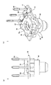
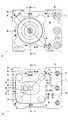
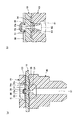
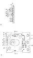
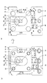
図1〜図4は、第1の実施の形態に係る半導体センサ装置を例示する図である。なお、図1(a)は正面図、図1(b)は斜視図、図2(a)は平面図、図2(b)は底面図、図3(a)は図2のA−A線に沿う断面図、図3(b)は図3(a)のC部の拡大図、図4は図2のB−B線に沿う断面図である。又、図5〜図14は、第1の実施の形態に係る半導体センサ装置の製造工程を例示する図である。
まず、図1〜図5を参照しながら、第1の実施の形態に係る半導体センサ装置1の構造について説明する。図1〜図5に示すように、半導体センサ装置1は、大略すると、基板10と、シリンダ70と、ノズル80と、外部端子90とを有する。シリンダ70とノズル80とは基板10を挟んだ状態で接合されている。
次に、図5〜図14を参照しながら、第1の実施の形態に係る半導体センサ装置1の製造方法について説明する。まず、図5(a)に示す工程では、基板10を準備する。そして、図5(b)に示す工程では、基板10の部品実装用パッド13に実装部品40を実装する。具体的には、例えば、部品実装用パッド13にクリームはんだを塗布し、クリームはんだ上に実装部品40を配置し、リフロー等によりクリームはんだ等を溶融後凝固させる。なお、半導体センサ装置1では、基板10の上面又は下面に全ての実装部品が実装され、シリンダ70やノズル80に直接実装されることがないため、既存の実装機を使用して容易に製造が可能である。
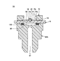
図15は、第1の実施の形態の変形例に係る半導体センサ装置を例示する断面図であり、図3(a)に対応する断面を示している。第1の実施の形態では、接着樹脂54及び55により圧力媒体をシールする例を示したが、これに代えて、図15に示す半導体センサ装置1Aのように、Oリング130により圧力媒体をシールする構造としてもよい。
10 基板
10x 圧力媒体導入孔
10y 位置決め孔
10z 外部端子挿入孔
11 素子搭載領域
11a 圧力媒体導入孔の周辺領域
12 ボンディングパッド
13 部品実装用パッド
14 外部端子実装用パッド
15 ソルダーレジスト
15a、15b レジストスペーサ
16 スルーホール
18 テスト用パッド
20 半導体センサ素子
30 制御IC
40 実装部品
51、52、53 接着樹脂
54 シール用接着樹脂
55 ノズル接着樹脂
58 デバイス保護ゲル
59 基板保護ゲル
60 金属線
70 シリンダ
70x 開口部
70y 位置決め孔
70z 段差部
80、80A ノズル
81 圧力媒体導入孔
82 流量制限部
83 バッファ部
85 Oリング配置部
89 位置決め部
90 外部端子
110、120 ケース
130 Oリング
Claims (9)
- 基板と、
前記基板の一方の側に実装され、圧力媒体の圧力を検出する半導体センサ素子と、
前記基板の一方の側に実装され、前記半導体センサ素子を保護する保護部材と、
前記基板の他方の側に実装され、前記基板に設けられた貫通孔を介して前記半導体センサ素子に圧力媒体を導入する圧力媒体導入部材と、を有し、
前記保護部材と前記圧力媒体導入部材とが前記基板を挟んだ状態で接合されている半導体センサ装置。 - 前記圧力媒体導入部材は位置決め部を備え、
前記位置決め部は前記基板及び前記保護部材を連通する位置決め孔に挿入され、前記位置決め部の先端が前記保護部材の表面から突出し、
前記突出した部分が熱溶着により前記保護部材の表面と接合されている請求項1記載の半導体センサ装置。 - 前記圧力媒体導入部材は、前記基板の他方の側の前記貫通孔の外側に環状に設けられた第1の接着樹脂と、前記第1の接着樹脂の更に外側に設けられた第2の接着樹脂により、前記基板と接着されている請求項1又は2記載の半導体センサ装置。
- 前記第1の接着樹脂はフッ素系の樹脂であり、前記第2の接着樹脂はシリコーン系の樹脂である請求項3記載の半導体センサ装置。
- 前記圧力媒体導入部材は、圧力媒体導入孔を備え、
前記圧力媒体導入孔は、前記基板と遠い方から近い方にかけて、第1の断面積を備えた第1の部分と、前記第1の断面積よりも小さい第2の断面積を備えた第2の部分と、前記第2の断面積よりも大きい第3の断面積を備えた第3の部分と、を有している請求項1乃至4の何れか一項記載の半導体センサ装置。 - 前記第2の部分の断面積は、前記第1の部分側から前記第3の部分側に近づくにつれて徐々に小さくなる請求項5記載の半導体センサ装置。
- 全ての実装部品が前記基板上に実装されている請求項1乃至6の何れか一項記載の半導体センサ装置。
- 前記保護部材は開口部を備え、
平面視において、前記半導体センサ素子の中心から前記開口部の内壁面までの距離が、点対称の関係である請求項1乃至7の何れか一項記載の半導体センサ装置。 - 前記圧力媒体がガスである請求項1乃至8の何れか一項記載の半導体センサ装置。
Priority Applications (4)
| Application Number | Priority Date | Filing Date | Title |
|---|---|---|---|
| JP2014242203A JP6428205B2 (ja) | 2014-11-28 | 2014-11-28 | 半導体センサ装置 |
| EP15863885.8A EP3225964B1 (en) | 2014-11-28 | 2015-11-16 | Semiconductor sensor device |
| CN201580065969.XA CN107003199B (zh) | 2014-11-28 | 2015-11-16 | 半导体传感器装置 |
| PCT/JP2015/082117 WO2016084641A1 (ja) | 2014-11-28 | 2015-11-16 | 半導体センサ装置 |
Applications Claiming Priority (1)
| Application Number | Priority Date | Filing Date | Title |
|---|---|---|---|
| JP2014242203A JP6428205B2 (ja) | 2014-11-28 | 2014-11-28 | 半導体センサ装置 |
Related Child Applications (2)
| Application Number | Title | Priority Date | Filing Date |
|---|---|---|---|
| JP2018172130A Division JP6725852B2 (ja) | 2018-09-14 | 2018-09-14 | 半導体センサ装置 |
| JP2018172129A Division JP6562142B2 (ja) | 2018-09-14 | 2018-09-14 | 半導体センサ装置 |
Publications (2)
| Publication Number | Publication Date |
|---|---|
| JP2016102761A true JP2016102761A (ja) | 2016-06-02 |
| JP6428205B2 JP6428205B2 (ja) | 2018-11-28 |
Family
ID=56074208
Family Applications (1)
| Application Number | Title | Priority Date | Filing Date |
|---|---|---|---|
| JP2014242203A Active JP6428205B2 (ja) | 2014-11-28 | 2014-11-28 | 半導体センサ装置 |
Country Status (4)
| Country | Link |
|---|---|
| EP (1) | EP3225964B1 (ja) |
| JP (1) | JP6428205B2 (ja) |
| CN (1) | CN107003199B (ja) |
| WO (1) | WO2016084641A1 (ja) |
Citations (3)
| Publication number | Priority date | Publication date | Assignee | Title |
|---|---|---|---|---|
| JPH0943084A (ja) * | 1995-07-28 | 1997-02-14 | Denso Corp | センサ装置及びセンサチップの固着方法 |
| JPH10160604A (ja) * | 1996-11-27 | 1998-06-19 | Matsushita Electric Works Ltd | 圧力センサ |
| JP2003254849A (ja) * | 2002-02-28 | 2003-09-10 | Sunx Ltd | 圧力検出器及び圧力センサ |
Family Cites Families (4)
| Publication number | Priority date | Publication date | Assignee | Title |
|---|---|---|---|---|
| JP3410257B2 (ja) * | 1995-07-31 | 2003-05-26 | 株式会社デンソー | 圧力センサ |
| US7024937B2 (en) * | 2003-12-03 | 2006-04-11 | Honeywell International Inc. | Isolated pressure transducer |
| JP5847385B2 (ja) * | 2010-08-31 | 2016-01-20 | ミツミ電機株式会社 | 圧力センサ装置及び該装置を備える電子機器、並びに該装置の実装方法 |
| DE102013101731A1 (de) * | 2013-02-21 | 2014-09-04 | Epcos Ag | Drucksensorsystem |
-
2014
- 2014-11-28 JP JP2014242203A patent/JP6428205B2/ja active Active
-
2015
- 2015-11-16 CN CN201580065969.XA patent/CN107003199B/zh active Active
- 2015-11-16 WO PCT/JP2015/082117 patent/WO2016084641A1/ja not_active Ceased
- 2015-11-16 EP EP15863885.8A patent/EP3225964B1/en active Active
Patent Citations (3)
| Publication number | Priority date | Publication date | Assignee | Title |
|---|---|---|---|---|
| JPH0943084A (ja) * | 1995-07-28 | 1997-02-14 | Denso Corp | センサ装置及びセンサチップの固着方法 |
| JPH10160604A (ja) * | 1996-11-27 | 1998-06-19 | Matsushita Electric Works Ltd | 圧力センサ |
| JP2003254849A (ja) * | 2002-02-28 | 2003-09-10 | Sunx Ltd | 圧力検出器及び圧力センサ |
Also Published As
| Publication number | Publication date |
|---|---|
| JP6428205B2 (ja) | 2018-11-28 |
| EP3225964A4 (en) | 2018-10-24 |
| EP3225964B1 (en) | 2019-09-18 |
| CN107003199B (zh) | 2020-01-07 |
| WO2016084641A1 (ja) | 2016-06-02 |
| CN107003199A (zh) | 2017-08-01 |
| EP3225964A1 (en) | 2017-10-04 |
Similar Documents
| Publication | Publication Date | Title |
|---|---|---|
| KR101236678B1 (ko) | 압력 센서 장치 | |
| JP4548066B2 (ja) | 圧力センサ | |
| EP2316008B1 (en) | Sensor device packaging and corresponding method | |
| KR101109282B1 (ko) | 압력 센서장치 | |
| CN101375146B (zh) | 压力传感器封装体和电子器件 | |
| US11146893B2 (en) | Sensor system, sensor arrangement, and assembly method using solder for sealing | |
| JP6588321B2 (ja) | 圧力センサ | |
| JP5320863B2 (ja) | 電子部品 | |
| JP6562142B2 (ja) | 半導体センサ装置 | |
| JP6428205B2 (ja) | 半導体センサ装置 | |
| JP6725852B2 (ja) | 半導体センサ装置 | |
| JP6507596B2 (ja) | 半導体センサ装置 | |
| JP6580079B2 (ja) | 圧力センサ、および、圧力センサの製造方法 | |
| WO2022080130A1 (ja) | センサモジュールおよびその製造方法 | |
| JP6554786B2 (ja) | 半導体センサ装置 | |
| JP6507595B2 (ja) | 半導体センサ装置 | |
| CN220853975U (zh) | 压力传感器 | |
| JP2019024084A (ja) | 半導体装置及び半導体装置の製造方法 | |
| JP6970862B1 (ja) | 半導体力センサ | |
| JP4045988B2 (ja) | 圧力センサ | |
| JP2006194682A (ja) | 温度センサ一体型圧力センサ装置 | |
| JP4983329B2 (ja) | センサ装置 | |
| CN110431394A (zh) | 压力传感器 | |
| WO2024004248A1 (ja) | 圧力センサ | |
| CN117723196A (zh) | 压力传感器 |
Legal Events
| Date | Code | Title | Description |
|---|---|---|---|
| A621 | Written request for application examination |
Free format text: JAPANESE INTERMEDIATE CODE: A621 Effective date: 20171020 |
|
| A131 | Notification of reasons for refusal |
Free format text: JAPANESE INTERMEDIATE CODE: A131 Effective date: 20180717 |
|
| A521 | Request for written amendment filed |
Free format text: JAPANESE INTERMEDIATE CODE: A523 Effective date: 20180914 |
|
| TRDD | Decision of grant or rejection written | ||
| A01 | Written decision to grant a patent or to grant a registration (utility model) |
Free format text: JAPANESE INTERMEDIATE CODE: A01 Effective date: 20181002 |
|
| A61 | First payment of annual fees (during grant procedure) |
Free format text: JAPANESE INTERMEDIATE CODE: A61 Effective date: 20181015 |
|
| R150 | Certificate of patent or registration of utility model |
Ref document number: 6428205 Country of ref document: JP Free format text: JAPANESE INTERMEDIATE CODE: R150 |