JP2016110856A - Flat battery - Google Patents
Flat battery Download PDFInfo
- Publication number
- JP2016110856A JP2016110856A JP2014247770A JP2014247770A JP2016110856A JP 2016110856 A JP2016110856 A JP 2016110856A JP 2014247770 A JP2014247770 A JP 2014247770A JP 2014247770 A JP2014247770 A JP 2014247770A JP 2016110856 A JP2016110856 A JP 2016110856A
- Authority
- JP
- Japan
- Prior art keywords
- electrode plate
- electrode group
- fixing member
- positive electrode
- negative electrode
- Prior art date
- Legal status (The legal status is an assumption and is not a legal conclusion. Google has not performed a legal analysis and makes no representation as to the accuracy of the status listed.)
- Pending
Links
- 229910052751 metal Inorganic materials 0.000 claims abstract description 31
- 239000002184 metal Substances 0.000 claims abstract description 31
- 239000011888 foil Substances 0.000 claims abstract description 26
- 239000011149 active material Substances 0.000 claims abstract description 23
- 239000010410 layer Substances 0.000 description 49
- 230000004048 modification Effects 0.000 description 38
- 238000012986 modification Methods 0.000 description 38
- 238000000034 method Methods 0.000 description 13
- 239000000853 adhesive Substances 0.000 description 8
- 230000001070 adhesive effect Effects 0.000 description 8
- 238000005452 bending Methods 0.000 description 7
- 238000004519 manufacturing process Methods 0.000 description 6
- 239000000463 material Substances 0.000 description 6
- 230000006866 deterioration Effects 0.000 description 5
- 125000006850 spacer group Chemical group 0.000 description 5
- 238000003466 welding Methods 0.000 description 5
- 239000012790 adhesive layer Substances 0.000 description 4
- 239000002390 adhesive tape Substances 0.000 description 3
- 239000011230 binding agent Substances 0.000 description 3
- 239000003795 chemical substances by application Substances 0.000 description 3
- 238000010030 laminating Methods 0.000 description 3
- 229910052744 lithium Inorganic materials 0.000 description 3
- 239000000203 mixture Substances 0.000 description 3
- OKTJSMMVPCPJKN-UHFFFAOYSA-N Carbon Chemical compound [C] OKTJSMMVPCPJKN-UHFFFAOYSA-N 0.000 description 2
- KMTRUDSVKNLOMY-UHFFFAOYSA-N Ethylene carbonate Chemical compound O=C1OCCO1 KMTRUDSVKNLOMY-UHFFFAOYSA-N 0.000 description 2
- WHXSMMKQMYFTQS-UHFFFAOYSA-N Lithium Chemical compound [Li] WHXSMMKQMYFTQS-UHFFFAOYSA-N 0.000 description 2
- 239000002033 PVDF binder Substances 0.000 description 2
- 238000005336 cracking Methods 0.000 description 2
- 238000005520 cutting process Methods 0.000 description 2
- 238000010586 diagram Methods 0.000 description 2
- 230000005611 electricity Effects 0.000 description 2
- 239000008151 electrolyte solution Substances 0.000 description 2
- 230000002093 peripheral effect Effects 0.000 description 2
- 229920002981 polyvinylidene fluoride Polymers 0.000 description 2
- RUOJZAUFBMNUDX-UHFFFAOYSA-N propylene carbonate Chemical compound CC1COC(=O)O1 RUOJZAUFBMNUDX-UHFFFAOYSA-N 0.000 description 2
- RYGMFSIKBFXOCR-UHFFFAOYSA-N Copper Chemical compound [Cu] RYGMFSIKBFXOCR-UHFFFAOYSA-N 0.000 description 1
- 229910012851 LiCoO 2 Inorganic materials 0.000 description 1
- 229910014689 LiMnO Inorganic materials 0.000 description 1
- 229910013290 LiNiO 2 Inorganic materials 0.000 description 1
- 229910013870 LiPF 6 Inorganic materials 0.000 description 1
- 239000004820 Pressure-sensitive adhesive Substances 0.000 description 1
- 239000006230 acetylene black Substances 0.000 description 1
- NIXOWILDQLNWCW-UHFFFAOYSA-N acrylic acid group Chemical group C(C=C)(=O)O NIXOWILDQLNWCW-UHFFFAOYSA-N 0.000 description 1
- 229910052782 aluminium Inorganic materials 0.000 description 1
- XAGFODPZIPBFFR-UHFFFAOYSA-N aluminium Chemical compound [Al] XAGFODPZIPBFFR-UHFFFAOYSA-N 0.000 description 1
- 239000006258 conductive agent Substances 0.000 description 1
- 238000007796 conventional method Methods 0.000 description 1
- 239000011889 copper foil Substances 0.000 description 1
- 230000001351 cycling effect Effects 0.000 description 1
- 230000007423 decrease Effects 0.000 description 1
- 230000007547 defect Effects 0.000 description 1
- QHGJSLXSVXVKHZ-UHFFFAOYSA-N dilithium;dioxido(dioxo)manganese Chemical compound [Li+].[Li+].[O-][Mn]([O-])(=O)=O QHGJSLXSVXVKHZ-UHFFFAOYSA-N 0.000 description 1
- 239000000428 dust Substances 0.000 description 1
- 239000003792 electrolyte Substances 0.000 description 1
- 238000007306 functionalization reaction Methods 0.000 description 1
- 229910002804 graphite Inorganic materials 0.000 description 1
- 239000010439 graphite Substances 0.000 description 1
- 239000012535 impurity Substances 0.000 description 1
- 230000001788 irregular Effects 0.000 description 1
- 238000003475 lamination Methods 0.000 description 1
- -1 lithium hexafluorophosphate Chemical compound 0.000 description 1
- 229910003002 lithium salt Inorganic materials 0.000 description 1
- 159000000002 lithium salts Chemical class 0.000 description 1
- 239000007769 metal material Substances 0.000 description 1
- 239000002923 metal particle Substances 0.000 description 1
- 239000007773 negative electrode material Substances 0.000 description 1
- 229910052755 nonmetal Inorganic materials 0.000 description 1
- 229920000728 polyester Polymers 0.000 description 1
- 239000007774 positive electrode material Substances 0.000 description 1
- 238000003825 pressing Methods 0.000 description 1
- 238000000926 separation method Methods 0.000 description 1
- 239000002904 solvent Substances 0.000 description 1
- 229910001220 stainless steel Inorganic materials 0.000 description 1
- 239000010935 stainless steel Substances 0.000 description 1
- 238000003860 storage Methods 0.000 description 1
Images









Classifications
-
- Y—GENERAL TAGGING OF NEW TECHNOLOGICAL DEVELOPMENTS; GENERAL TAGGING OF CROSS-SECTIONAL TECHNOLOGIES SPANNING OVER SEVERAL SECTIONS OF THE IPC; TECHNICAL SUBJECTS COVERED BY FORMER USPC CROSS-REFERENCE ART COLLECTIONS [XRACs] AND DIGESTS
- Y02—TECHNOLOGIES OR APPLICATIONS FOR MITIGATION OR ADAPTATION AGAINST CLIMATE CHANGE
- Y02E—REDUCTION OF GREENHOUSE GAS [GHG] EMISSIONS, RELATED TO ENERGY GENERATION, TRANSMISSION OR DISTRIBUTION
- Y02E60/00—Enabling technologies; Technologies with a potential or indirect contribution to GHG emissions mitigation
- Y02E60/10—Energy storage using batteries
-
- Y—GENERAL TAGGING OF NEW TECHNOLOGICAL DEVELOPMENTS; GENERAL TAGGING OF CROSS-SECTIONAL TECHNOLOGIES SPANNING OVER SEVERAL SECTIONS OF THE IPC; TECHNICAL SUBJECTS COVERED BY FORMER USPC CROSS-REFERENCE ART COLLECTIONS [XRACs] AND DIGESTS
- Y02—TECHNOLOGIES OR APPLICATIONS FOR MITIGATION OR ADAPTATION AGAINST CLIMATE CHANGE
- Y02P—CLIMATE CHANGE MITIGATION TECHNOLOGIES IN THE PRODUCTION OR PROCESSING OF GOODS
- Y02P70/00—Climate change mitigation technologies in the production process for final industrial or consumer products
- Y02P70/50—Manufacturing or production processes characterised by the final manufactured product
Landscapes
- Primary Cells (AREA)
- Secondary Cells (AREA)
Abstract
Description
本発明は活物質層による複数の層を形成した電極群を収納体に内包した扁平型電池に関する。 The present invention relates to a flat battery in which an electrode group in which a plurality of layers of active material layers are formed is enclosed in a storage body.
電池は、金属箔の表面に活物質層(所定の活物質とバインダー剤との混合物)を設けてなる正極及び負極の電極板を、セパレータを介して電気的に絶縁した状態で対向させ、その間に電解液を介在させる構造を有している。 In the battery, positive and negative electrode plates, each having an active material layer (a mixture of a predetermined active material and a binder agent) provided on the surface of a metal foil, are opposed to each other while being electrically insulated through a separator. It has a structure in which an electrolyte is interposed.
電極板同士が対向してなる構成を電極群と呼び、この電極群を所定の形状の電池ケースに収納し、電池ケースの所定の電極端子に正極及び負極をそれぞれ電気的に接続することで、一次又は二次電池として機能する。 The configuration in which the electrode plates are opposed to each other is called an electrode group, this electrode group is housed in a battery case of a predetermined shape, and a positive electrode and a negative electrode are electrically connected to predetermined electrode terminals of the battery case, respectively. Functions as a primary or secondary battery.
ボタン型やコインセル型に代表される扁平型電池は、多くの場合、電池ケースが金属で構成されており、それぞれの極性の電極端子を兼ねている。この電池ケースは、正極の電極端子となるケースと、負極の電極端子となるケースとが電気的に絶縁された状態で嵌合や接着などで固定されている。 In many cases, a flat battery represented by a button type or a coin cell type has a battery case made of metal and serves also as an electrode terminal of each polarity. The battery case is fixed by fitting or bonding in a state where the case serving as the positive electrode terminal and the case serving as the negative electrode terminal are electrically insulated.
特に近年、高機能携帯電話や小型情報端末等の携帯電子機器の進歩に伴い、搭載される電池もますます小型薄型化が求められており、扁平型電池が採用される機会が多くなってきている。同時に、このような電子機器の多機能化によって機器の消費電力も増大する傾向にあり、より電池容量が大きい扁平型の一次、二次電池が求められている。こうした背景から、一次電池の場合は放電レートが高く、二次電池の場合は充放電レートが高く、しかも薄型かつ小型大容量の扁平型電池の提案が多くなされている。 Particularly in recent years, with the advancement of portable electronic devices such as high-function mobile phones and small information terminals, batteries to be mounted are increasingly required to be smaller and thinner, and there are more opportunities to adopt flat batteries. Yes. At the same time, the power consumption of the devices tends to increase due to the multi-functionalization of such electronic devices, and flat primary and secondary batteries with larger battery capacities are demanded. Against this background, many proposals have been made for flat batteries having a high discharge rate in the case of primary batteries and a high charge / discharge rate in the case of secondary batteries, and which are thin, small and large in capacity.
扁平型電池は、小型で薄い形状であるため、電池ケースの限られたスペースの中で正極の電極板(以下、正極板と称する)と負極の電極板(以下、負極板と称する)とを対向させただけでは十分な蓄電量を確保できない。そこで、より多くの蓄電量を得るために、電池ケースよりも大きな面積の電極板を用いるものが多い。 Since a flat battery is small and thin, a positive electrode plate (hereinafter referred to as a positive plate) and a negative electrode plate (hereinafter referred to as a negative plate) in a limited space of the battery case. It is not possible to ensure a sufficient amount of electricity stored just by facing them. Therefore, in order to obtain a larger amount of stored electricity, many use an electrode plate having a larger area than the battery case.
そのような構成の扁平型電池にあっては、大きな面積の電極板を如何にして所定のサイズの電池ケースに収納するかが重要であって、それに関する技術も多くの提案がなされている。例えば、正極板と負極板とを対向させて折り畳む技術や、双方の極性の電極板をそれぞれ複数用い、それらを積層する技術などである。 In a flat battery having such a configuration, it is important how to store a large-area electrode plate in a battery case of a predetermined size, and many proposals have been made on techniques related to it. For example, there are a technique of folding the positive electrode plate and the negative electrode plate facing each other, a technique of using a plurality of electrode plates of both polarities, and laminating them.
また、電極板を折り畳んだり積層したりすると、電極群を形成してもその重ね合せがずれてしまうことがある。そのようなずれを積層ずれと呼び、この積層ずれが起こると、正極板と負極板との対向面積が低下してしまったり、重ね合せが層ごとに不規則になったりする。また、電極群の形状が崩れてしまうこともある。そうすると、電池容量の低下や、電池ケースから電極板の一部がはみ出してしまうなどの不良を発生させてしまう。このため、積層ずれを防ぐことも大変重要であり多くの提案をみるものである(例えば、特許文献1参照。)。 In addition, when the electrode plates are folded or stacked, even if an electrode group is formed, the overlay may be shifted. Such a shift is called a stacking shift. When this stacking shift occurs, the facing area between the positive electrode plate and the negative electrode plate is reduced, or the stacking is irregular for each layer. In addition, the shape of the electrode group may collapse. If it does so, defects, such as a fall of battery capacity and a part of electrode plate protruding from a battery case, will generate | occur | produce. For this reason, it is very important to prevent misalignment, and many proposals are seen (for example, refer to Patent Document 1).
ここで、特許文献1に示した従来技術の扁平型電池(コイン形電池)の概略を、図を用いて説明する。まず構造を、図16を用いて説明する。
図16において、扁平型電池を構成する電極群100は、平面視で略円形の負極板101(実線で示す)と正極板102(点線で示す)とが交互に積層して構成されている。こ
の電極群100の外周は、それぞれ一対の直線部と円弧部を有している。そして、負極板101の直線部の中央からは、負極リード101aが導出され、すべての負極リード101aが結束して、図示しない電池容器の負極缶に接続されている。
Here, an outline of a conventional flat battery (coin-type battery) shown in
In FIG. 16, the
一方、正極板102の直線部の中央からは、正極リード102aが導出され、すべての正極リード102aが結束して、図示しない電池容器の正極缶に接続されている。なお、正極102は、図示しないセパレータで覆われ、負極板101と正極板102とは、電気的に絶縁している。
On the other hand, a positive electrode lead 102a is led out from the center of the straight portion of the
また、電極群100の一対の円弧部は、電極群100の上端面から側面に沿って下端面に至るように貼り付けられた第1の結束テープ103a、103bによって結束されている。また、電極群100の一対の直線部は、電極群100の上端面から側面に沿って下端面に至るように貼り付けられた第2の結束テープ104a、104bによって結束されている。
Further, the pair of arc portions of the
このように、電極群100の各円弧部及び各直線部が、第1の結束テープ103a、103bと、第2の結束テープ104a、104bとにより、計4箇所に分散して結束され、固定されているので、負極板101と正極板102との積層ずれを防ぐことができる。
In this way, each arc part and each straight line part of the
しかしながら、特許文献1に示した従来技術は、負極板101と正極板102とで構成される電極群100を4箇所の結束テープで固定しているために、結束テープの取り付け工程が複雑であり、電池の製造工数が増えてしまうという問題を有している。扁平型電池は小型のものが多く、4箇所の結束テープの固定作業時に電極板を傷つけてしまうこともあり、それが電池の信頼性を低下させる要因にもなっていた。
However, in the prior art disclosed in
また、電極群100を電池ケースに内包すると、結束テープの厚みによって正極板と負極板との電極部(活物質層を形成している部分)に段差が生じ、電池としての特性が劣化し、信頼性が低下する問題がある。以下、その問題を図17を用いて詳述する。
In addition, when the
図17は、特許文献1に示した従来技術の問題を説明するために、電極群100を電池ケースに内包する様子を模式的に示した図であって、電極群100の結束テープ103a付近(図16参照)の断面を示した断面図である。
FIG. 17 is a diagram schematically showing a state in which the
図17において、扁平型電池を完成させるために電極群100を電池ケース200の内部に載置し、電池ケース200の正極缶201と負極缶202とを嵌合する。このとき、正極缶201及び負極缶202に上下方向から圧力Pが加えられるが、この圧力Pが正極缶201と負極缶202とに対して均一だったとしても、電極群100の上端面には、結束テープ103aがあるために、圧力Pは電極群100に均一には加わらない。
In FIG. 17, in order to complete the flat battery, the
すなわち、図17に示したように、電極群100に圧力Pが加わると、結束テープ103aが電極群100に厚み方向で重なっている部分が、重なっていない部分に比べて、結束テープ103aの厚み分だけ強く押し込まれてしまうのである。このため、領域Z(楕円の点線で示す)においては、電極群100を構成する負極板101と正極板102とに段差が生じてしまう。なお、図示していないが、電極群100の下端面にも結束テープ1
03aがあるならば、当然であるが、下端面側からも均一でない圧力が加えられて段差が生じることになる。
That is, as shown in FIG. 17, when the pressure P is applied to the
If there is 03a, it is natural that non-uniform pressure is applied also from the lower end surface side to cause a step.
この領域Zにおける形状変化によって、負極板101の電極部と正極板102の電極部とに局部的な歪みが生じ、素材(特に活物質層)の亀裂や劣化を生じ、二次電池であるならば、充放電特性(サイクル特性)の劣化を招くなど、電池としての信頼性が低下してしまうという課題がある。
If the shape change in this region Z causes local distortion in the electrode part of the
また、局部的な歪みによって電極間の距離の一様性が失われ、電極間の距離が他より狭い領域が生じると、その領域では電極間の電気抵抗が小さくなるので、例えばリチウムイオン二次電池の場合、充電時に電気抵抗が小さい領域に充電電流が集中的に流れる現象が発生する。その結果、電流の集中によって熱が発生し、その熱よってリチウム金属が負極上に析出し、最悪の場合、正極板と負極板とが短絡してしまうという課題もある。 Also, when the distance between the electrodes is lost due to local distortion and a region where the distance between the electrodes is narrower than the others is generated, the electrical resistance between the electrodes is reduced in that region. In the case of a battery, a phenomenon occurs in which a charging current flows intensively in a region where electric resistance is small during charging. As a result, heat is generated by the concentration of current, and lithium metal is deposited on the negative electrode due to the heat. In the worst case, there is a problem that the positive electrode plate and the negative electrode plate are short-circuited.
本発明の目的は上記課題を解決し、正極板と負極板との対向状態が平行平面になることで歪みや段差を無くし、高性能で信頼性に優れた扁平型電池を提供することである。 The object of the present invention is to solve the above-mentioned problems and to provide a flat battery having high performance and excellent reliability by eliminating the distortion and the step because the opposing state of the positive electrode plate and the negative electrode plate is a parallel plane. .
上記課題を解決するために、本発明の扁平型電池は、下記記載の構成を採用する。 In order to solve the above problems, the flat battery of the present invention employs the following configuration.
本発明の扁平型電池は、金属箔の表面に活物質層が形成された正極板及び負極板を有し、正極板と負極板とが対向するように複数の層を形成して、収納体に内包した扁平型電池において、正極板又は負極板の端面と、複数の層の側面と、を覆い正極板と負極板とが離間しないように固定する固定手段を設け、固定手段は、端面を覆う第1部分と、第1部分の端辺から延設して側面を覆う第2部分と、からなることを特徴とする。 The flat battery of the present invention has a positive electrode plate and a negative electrode plate on which an active material layer is formed on the surface of a metal foil, and a plurality of layers are formed so that the positive electrode plate and the negative electrode plate face each other. In the flat battery encapsulated in the battery, there is provided a fixing means for covering the end face of the positive electrode plate or the negative electrode plate and the side surfaces of the plurality of layers so that the positive electrode plate and the negative electrode plate are not separated from each other. It consists of the 1st part which covers, and the 2nd part which extends from the edge of the 1st part and covers a side surface, It is characterized by the above-mentioned.
上記構成により、正極板と負極板との端面を覆う第1部分と側面を覆う第2部分とによりなる固定手段を設けることで、正極板と負極板とが固定されて離間を防ぐので、高容量で信頼性に優れ、且つ、製造工程が簡略化された扁平型電池を提供できる。 With the above configuration, by providing a fixing means that includes a first part that covers the end faces of the positive electrode plate and the negative electrode plate and a second part that covers the side surfaces, the positive electrode plate and the negative electrode plate are fixed to prevent separation. It is possible to provide a flat battery having high capacity, high reliability, and a simplified manufacturing process.
また、第1部分は、複数の層における対向形状と略同じ大きさにしてもよい。 Further, the first portion may be approximately the same size as the opposing shape in the plurality of layers.
これにより、第1部分は、複数の層における対向形状と略同じ大きさに構成されるので、正極板と負極板との対向状態が平行平面になって歪みや段差を防ぐことができる。その結果、活物質層等の亀裂や劣化を防いで、電池としての信頼性が高く、二次電池の場合はサイクル特性に優れた扁平型電池を提供できる。 Thereby, since the 1st part is comprised in the substantially same magnitude | size as the opposing shape in a some layer, the opposing state of a positive electrode plate and a negative electrode plate becomes a parallel plane, and it can prevent a distortion and a level | step difference. As a result, it is possible to provide a flat battery that prevents cracks and deterioration of the active material layer, has high reliability as a battery, and has excellent cycle characteristics in the case of a secondary battery.
また、第2部分は、第1部分よりも面積が小さくてもよい。 Further, the area of the second portion may be smaller than that of the first portion.
これにより、第2部分の形状を小さく、例えば、帯状に細くすることで、正極板と負極板との複数の層による平面視の形状が多角形または円形等であっても、第2部分が複数の層の外周から大きくはみ出さすことなく側面を覆い固定することができる。 Thereby, the shape of the second portion is made small, for example, thin in a band shape, so that even if the shape in plan view by the plurality of layers of the positive electrode plate and the negative electrode plate is polygonal or circular, the second portion is The side surfaces can be covered and fixed without protruding greatly from the outer periphery of the plurality of layers.
また、第2部分は、その端部に折り返し部を有し、折り返し部は、正極板又は負極板の他の端面と接するようにしてもよい。 Further, the second portion may have a folded portion at an end thereof, and the folded portion may be in contact with the other end surface of the positive electrode plate or the negative electrode plate.
これにより、第2部分の端部が正極板又は負極板の他の端面を覆う構成となるので、正極板と負極板とを挟み込むようにして固定でき、正極板と負極板との離間を確実に防ぐことができる。 As a result, the end portion of the second portion covers the other end face of the positive electrode plate or the negative electrode plate, so that the positive electrode plate and the negative electrode plate can be sandwiched and fixed, and the positive electrode plate and the negative electrode plate are reliably separated. Can be prevented.
本発明の扁平型電池によれば、正極板と負極板との端面を覆う第1部分と側面を覆う第2部分とによりなる固定手段を備えることで、正極板と負極板とが固定されて離間しなくなると共に、正極板と負極板との対向状態が平行平面になって歪みや段差の発生を防ぐので、活物質層等の亀裂や劣化を防止し、電池としての信頼性が高く、二次電池の場合はサイクル特性に優れた高容量の扁平型電池を提供できる。 According to the flat battery of the present invention, the positive electrode plate and the negative electrode plate are fixed by including the fixing means including the first part covering the end faces of the positive electrode plate and the negative electrode plate and the second part covering the side surface. Since the positive electrode plate and the negative electrode plate face each other in a parallel plane and prevent the occurrence of distortion and steps, cracks and deterioration of the active material layer and the like are prevented, and the battery is highly reliable. In the case of a secondary battery, a high capacity flat battery excellent in cycle characteristics can be provided.
以下図面に基づいて本発明の扁平型電池の具体的な実施の形態、及びその変形例を詳述する。特に限定するものではないが、説明にあっては、扁平型二次電池を例にして説明する。 Hereinafter, specific embodiments of the flat battery of the present invention and modifications thereof will be described in detail with reference to the drawings. Although not particularly limited, a flat secondary battery will be described as an example in the description.
[実施形態の説明]
扁平型電池の第1の実施形態は、固定手段の第1部分は正極板と負極板の複数の層における対向形状と略同じ大きさであり、電極群の一方の端面を覆い、固定手段の第2部分は第1部分の端辺の一辺から延設し電極群の側面を覆う構成される。
[Description of Embodiment]
In the first embodiment of the flat battery, the first portion of the fixing means is substantially the same size as the opposing shape in the plurality of layers of the positive electrode plate and the negative electrode plate, covers one end surface of the electrode group, The second part extends from one side of the end of the first part and covers the side surface of the electrode group.
第2の実施形態は、固定手段の第1部分は正極板と負極板の複数の層における対向形状と略同じ大きさであり、固定手段の第2部分は第1部分の端辺の二辺から延設して構成される。 In the second embodiment, the first portion of the fixing means is substantially the same size as the opposing shape in the plurality of layers of the positive electrode plate and the negative electrode plate, and the second portion of the fixing means is the two sides of the end of the first portion. It is configured to extend from.
第3の実施形態は、固定手段の第1部分は正極板と負極板の複数の層における対向形状と略同じ大きさであり、第2部分の端部に第3部分を有し、この第3部分が電極群の他方の端面に回り込むように構成される。 In the third embodiment, the first part of the fixing means has substantially the same size as the opposing shape in the plurality of layers of the positive electrode plate and the negative electrode plate, and has a third part at the end of the second part. The three portions are configured to wrap around the other end face of the electrode group.
なお、各実施形態の説明及び図は一実施形態であって、これに限定されるものではない。また、図面における寸法は実際の形状を反映したものではなく図面を見やすくするため、一部誇張して記載している場合がある。また、発明に直接関係しない一部の要素は省略し、各実施形態において同一又は相当する要素には同一番号を付与して重複する説明は省略するものとする。 In addition, description and figure of each embodiment are one Embodiment, Comprising: It is not limited to this. In addition, dimensions in the drawings do not reflect actual shapes and may be exaggerated in part in order to make the drawings easier to see. In addition, some elements not directly related to the invention are omitted, and the same or corresponding elements in each embodiment are given the same numbers, and redundant descriptions are omitted.
[第1の実施形態の構成説明:図1]
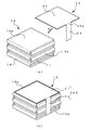
まず、第1の実施形態の扁平型電池の電極群及び固定部材の構成を、図1を用いて説明する。
図1(a)は第1の実施形態の電極群の斜視図であり、図1(b)は図1(a)で示す切断線A−A´による電極群の断面図である。
[Description of Configuration of First Embodiment: FIG. 1]
First, the configuration of the electrode group and the fixing member of the flat battery according to the first embodiment will be described with reference to FIG.
FIG. 1A is a perspective view of the electrode group of the first embodiment, and FIG. 1B is a cross-sectional view of the electrode group along the cutting line AA ′ shown in FIG.
図1において、符号10は第1の実施形態の扁平型電池を構成する電極群である。なお、電極群とは、すでに説明したように、正極板と負極板とが対向して複数の層を形成した構成を称する。電極群10は、帯形状の正極板11と負極板16とのそれぞれの電極部同士を重ねて交互に折り畳む、九十九折りにて複数の層を形成したものを例として説明する。
In FIG. 1, the code |
九十九折りとは、帯形状の2つ構造物の一部を重ね、交互に折り畳む公知の手法である。本実施形態では、正極板及び負極板を構成する互いの電極部同士を重ね、正極板11と負極板16とを交互に折り畳むことで九十九折りとする。なお、電極群10は、九十九折りに限定されず、例えば、正極板と負極板とを対向して巻回する構成や、正極板と負極板とを重ね、交互に折り返す、所謂、蛇腹折りをして構成してもよい。
Ninety-nine folds are a known technique in which a part of two belt-shaped structures are overlapped and folded alternately. In the present embodiment, the electrode portions constituting the positive electrode plate and the negative electrode plate are overlapped with each other, and the
符号20は第1の実施形態の固定手段としての絶縁性の固定部材であり、粘着テープ等で構成される。固定部材20は、電極群10の一方の端面を覆う第1部分21と、第1部分21の端辺から延設して電極群10の複数の層の側面を覆う第2部分22と、からなる。
固定部材20が電極群10と接する面は粘着層を有しており、この固定部材20によって一方の端面と側面とを覆われた電極群10は、折り畳まれた正極板11と負極板16とが離間せず(積層ずれや、ばらけたりせず)、折り畳まれた状態を安定して保つことができる。
The surface where the fixing
電極群10は、製造工程の途中、移動や電池ケースへの組み込み工程で積層ずれを起こしたり、また、折り畳まれた電極板がばらけたりする可能性がある。そのような状態の電極群10が、電池ケースに組み込まれると、様々な問題が発生するが、この固定部材20によりそれを防ぐことができる。
There is a possibility that the
電極群10は、例示したように九十九折りすることで、正極板11と負極板16とが平面的に折り重なっている。いわば双方の電極板が噛み合っているような状態であるから、
固定部材20により電極群10の端面と側面とを固定すれば、双方の電極板が積層ずれを起こすことはない。
As illustrated, the
If the end surface and the side surface of the
電極群10の図面上の最上部は、正極板11の末端に形成される接続タブ部12が配置されている。接続タブ部12は、詳細は後述するが、電極群10を収納する電池ケースと正極板11とを電気的に接続するものである。この接続タブ部12は、電極群10の端面を覆う固定部材20の第1部分21の上側に位置し、固定部材20によっては固定されない。
A connection tab portion 12 formed at the end of the
この配置によって、電極群10が後述する電池ケースに収納されると、接続タブ部12は電極群10の最上部に位置するので、接続タブ部12と電池ケースが接することができるのである。なお、図1(b)は接続タブ部12の図示を省略している。
With this arrangement, when the
また、電極群10の図面上の最下部は、負極板16の末端に形成される接続タブ部17が配置されている。接続タブ部17は、詳細は後述するが、電池ケースと負極板16とを電気的に接続するものである。
A
また、電極群10の形状は平面視で四角形であるが、形状は任意であり、例えば、多角形や円形等でもよい。なお、正極板11と負極板16との間には、双方を電気的に絶縁するセパレータが配置されるが、セパレータは本発明に直接関係しない要素であるので、図示は省略する。
The shape of the
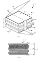
[正極板と負極板の説明:図2]
次に、第1の実施形態の扁平型電池を構成する電極群を形成する、正極板及び負極板の構成を、図2を用いて説明する。
図2(a)は正極板及び負極板の平面図であり、図2(b)は図2(a)で示す切断線B−B´による正極板の厚み方向の断面図である。
[Explanation of positive and negative plates: FIG. 2]
Next, the structure of the positive electrode plate and the negative electrode plate which form the electrode group which comprises the flat battery of 1st Embodiment is demonstrated using FIG.
2A is a plan view of the positive electrode plate and the negative electrode plate, and FIG. 2B is a cross-sectional view in the thickness direction of the positive electrode plate taken along the cutting line BB ′ shown in FIG.
図2において、正極板11は、帯形状の金属箔11pの表面の所定の部分に複数の活物質層を設けている。活物質層は平面視で、例えば、四角形で構成している。これら活物質層は、正極板11の電極部となり、正極部13と称する。各正極部13の間は金属箔11pによって接続されており、この部分を接続部11rと称する。この接続部11rは、活物質層が設けられておらず金属箔11pが露出している状態となっている。
In FIG. 2, the
正極板11の金属箔11pは正極集電体とも呼ばれ、例えば、アルミニウム箔を用いる。その厚みは、例えば、20μmである。この金属箔11pの表面に、ニッケル酸リチウム(LiNiO2)、マンガン酸リチウム(LiMnO2)、コバルト酸リチウム(LiCoO2)等の正極活物質と、アセチレンブラック等の導電剤及び、ポリフッ化ビニリデン等のバインダー剤との混合物で構成した活物資層を形成する。
The metal foil 11p of the
この活物質層を所定の形状に形成することで、正極板11の電極部である複数の正極部13が構成される。なお、正極部13は、図2(b)の断面図に示すように、金属箔11pを挟んで、金属箔11pの表面と裏面に対向して形成される。
By forming this active material layer in a predetermined shape, a plurality of positive electrode portions 13 which are electrode portions of the
正極板11の図面上の下側の末端には、金属箔11pを延出した接続タブ部12が配置されている。この接続タブ部12は、前述したように、正極板11を後述する電池ケースと電気的に接続するためのものであり、一例として接続タブ部12と電池ケースとは溶接によって電気的に接続される。このために、接続タブ部12の表面は、金属箔11pが露出している。接続タブ部12の平面視の大きさと形状は、正極部13と略等しく、この例では四角形である。
At the lower end of the
負極板16は、正極板11と同様に、帯形状の金属箔16pの表面の所定の部分に複数の活物質層を設けている。活物質層は平面視で例えば、正極板11と同様に四角形で構成している。これら活物質層は、負極板16の電極部となり、負極部18と称する。各負極部18の間は金属箔16pによって接続されており、この部分を接続部16rと称する。この接続部16rは、活物質層が設けられておらず金属箔16pが露出している状態となっている。
Similarly to the
負極板16の金属箔16pは負極集電体とも呼ばれ、例えば、銅箔を用いる。その厚みは、例えば、20μmである。この金属箔16pの表面に、グラファイト等の負極活物質とポリフッ化ビニリデン等のバインダー剤との混合物で構成した活物資層を設ける。
The metal foil 16p of the
この活物質層を所定の形状に形成することで、負極板16の電極部である複数の負極部18が構成される。なお、負極部18は、図示しないが正極部13と同様に、金属箔16pを挟んで、金属箔16pの表面と裏面に対向して形成される。
By forming this active material layer in a predetermined shape, a plurality of
負極板16の図面上の下側の末端には、金属箔16pを延出した接続タブ部17が配置されている。この接続タブ部17は、前述したように、負極板16を後述する電池ケースと電気的に接続するためのものであり、一例として接続タブ部17と電池ケースとは面接触によって電気的に接続される。このために、接続タブ部17の表面は、金属箔16pが露出している。接続タブ部17の平面視の大きさと形状は、負極部18と略等しく、この例では四角形である。
At the lower end of the
このような形状の電極板を九十九折りするのであるが、例えば、正極板11と負極板16とのどれか1つの電極部同士を重ね、正極板11と負極板16とを交互に折り畳むことで電極群10(図1参照)が完成する。
The electrode plate having such a shape is folded into ninety nines. For example, any one of the
[第1の実施形態の固定部材の説明:図3]
次に、第1の実施形態の扁平型電池を構成する固定部材の詳細構成を、図3を用いて説明する。
図3(a)は第1の実施形態の固定部材の平面図であり、図3(b)は固定部材を折り曲げた状態の斜視図である。図3(a)において、固定部材20は、前述したように、電極部10の端面を覆う第1部分21と、第1部分21の端辺から延設して電極群10の複数の層の側面を覆う第2部分22と、によって構成される。
[Description of Fixing Member of First Embodiment: FIG. 3]
Next, the detailed structure of the fixing member which comprises the flat battery of 1st Embodiment is demonstrated using FIG.
FIG. 3A is a plan view of the fixing member of the first embodiment, and FIG. 3B is a perspective view of the fixing member in a folded state. 3A, as described above, the fixing
固定部材20は、前述したように、絶縁性の粘着テープ等で構成され、電極群10と接する片側の面は粘着層(図示せず)に覆われた粘着面となっている。なお、固定部材20は粘着テープに限定されず、非金属であって厚みが薄い材料であればよい。また、後述する各実施形態及びその変形例の固定部材の材質は、第1の実施形態の固定部材20と同様である。
As described above, the fixing
第1部分21は、正極板11と負極板16による複数の層における対向形状(すなわち、正極部13と負極部18との層による平面視形状)と略同じ大きさであり、形状もこの例では正極部13と負極部18に合わせて四角形としている。このため、第1部分21で電極群10の端面を一様に覆うため、電極群10の端面に凹凸を作ることはない。
The
第2部分22は、第1部分21の端辺21aから延設して形成されている。図示する例では、その幅Wが一様な帯形状である。第2部分22の長さLは、電極群10の高さH(図1参照)に等しくするとよい。このようにすれば、第2部分22が電極群10の側面の高さ全体に接して覆うことができ、正極板と負極板とがばらけてしまうことを防止できる
。
The
図示した例では、第2部分22の幅Wは、第1部分21の一辺より短く(狭く)形成されているが、もちろんそれは一例であって、電極群10の形状などに鑑みて自由に決めることができる。しかし、幅Wを第1部分21の端辺21aの長さよりも短くすることで、図3(b)に示すように折り曲げたときに、その折り曲げ加工がしやすい。
In the illustrated example, the width W of the
第1部分21と第2部分22との繋がり部分には、折り曲げ部22aがある(点線で示す)。この折り曲げ部22aを基準にして、第2部分22を粘着面(図示せず)を内側にして約90度近くまで折り曲げるのである。図3(b)は、第2部分22を折り曲げ部22aを基準にして矢印Fの方向へ折り曲げた状態の固定部材20を示している。
The connecting portion between the
第2部分22の折り曲げ作業は、公知の把持部材を用いて第1部分21を固定し、公知の治具を用いて第2部分22を折り曲げる。なお、この折り曲げ作業は、固定部材20の第1部分21を電極群10に固着したあとで実施してもよい。
The
このように固定部材20は、第1部分21で電極群10の端面を一様に覆うため、電極群10の端面に凹凸を作ることはなく、第1部分21よりも面積が小さい第2部分22であるが、電極群10の側面を覆うことで、電極群10の積層ずれや電極板同士がばらけてしまうことを防止できる。
Thus, since the fixing
特に、第2部分の形状を小さく、例えば、本実施形態のように帯状に細くすることで、正極板と負極板との複数の層による平面視の形状が多角形または円形等であっても、第2部分が複数の層の外周から大きくはみ出さすことなく側面を覆い固定することができる。 In particular, by reducing the shape of the second portion, for example, by making it thin like a band as in this embodiment, even if the shape in plan view by a plurality of layers of the positive electrode plate and the negative electrode plate is polygonal or circular, etc. The second portion can cover and fix the side surface without protruding greatly from the outer periphery of the plurality of layers.
ところで、電極板の電極部となる正極部や負極部の平面視での形状は、図示した四角形の場合と、そうではない形状、例えば多角形や円形など様々な形状の場合がある。電極部の形状をどのようにするかは、電池の形状や性能から決まるものであるが、電極部の形状が平面視でどのような形状であっても、電極群の端面を覆う第1部分21と側面を覆う第2部分22とによる固定部材20によって、電極群10を確実に固定することができる。
By the way, the shape of the positive electrode part and the negative electrode part, which are electrode parts of the electrode plate, in a plan view may be various shapes such as a rectangular shape shown in the figure and other shapes such as a polygon or a circle. The shape of the electrode part is determined by the shape and performance of the battery, but the first part that covers the end face of the electrode group, regardless of the shape of the electrode part in plan view. The
[固定部材の電極群への取り付け説明:図4]
次に、固定部材を電極群に取り付ける工程を、図4を用いて説明する。
図4(a)は、固定部材の取り付け前の様子を示す斜視図であり、図4(b)は、固定部材の取り付け後の様子を示す斜視図である。なお、図4では電極群10の接続タブ部の図示を省略している。
[Explanation of fixing member to electrode group: Fig. 4]
Next, the process of attaching the fixing member to the electrode group will be described with reference to FIG.
FIG. 4A is a perspective view showing a state before the fixing member is attached, and FIG. 4B is a perspective view showing a state after the fixing member is attached. In FIG. 4, illustration of the connection tab portion of the
図4(a)において、固定部材20の第2部分22を折り曲げ部22aを基準にして折り曲げた後、公知の移動手段を用いて固定部材20を矢印Gの方向に移動させて、第1部分21の粘着面(内側)を正極板11と負極板16とでなる電極群10の一方の端面10aに接して固着し、次に、折り曲げた第2部分22の粘着面(内側)を電極群10の複数の層の側面10bに接して固着する。
In FIG. 4A, after the
そうすると、図4(b)に示す状態になる。すなわち、電極群10の一方の端面10aに固定部材20の第1部分21が固着して覆い、電極群10の側面10bに固定部材20の第2部分22が固着して覆っている。
これにより、電極群10の端面10aと側面10bは固定部材20によって覆われて固定されるので、電極板が積層ずれを起こしたり、折り畳まれた電極板がばらけてしまうこともなく、電池ケースに組み込むことができる。
Then, the state shown in FIG. That is, the
Thereby, since the end surface 10a and the side surface 10b of the
なお、電極群10と固定部材20との位置関係は、図示した例に限定されず、例えば、固定部材20の第1部分21が、電極群10の図面上の下側の端面を覆ってもよいし、第2部分22は、接続タブ部12、17(図1参照)が邪魔にならない側面であれば、電極群10のどの側面を覆ってもよい。
The positional relationship between the
このように、固定部材20は、電極群10の端面を覆う第1部分21と側面を覆う第2部分22とが一体の形状であるので、電極群10の離間を防ぐ固定作業(固定部材の取り付け作業)が従来例と比較して簡単であり、扁平型電池の製造工程の簡略化を実現できる。
As described above, the fixing
[電極群の電池ケースへの組み込み説明:図5]
次に、電極群を電池ケースに組み込んで扁平型電池を完成される工程を、図5を用いて説明する。
図5(a)は電極群を電池ケースに収納し、電極板と電池ケースとを接続する工程を示す断面図であり、図5(b)は電池ケースを嵌合して扁平型電池を完成する断面図である。
[Explanation of assembly of electrode group into battery case: Fig. 5]
Next, a process of completing the flat battery by incorporating the electrode group into the battery case will be described with reference to FIG.
FIG. 5A is a cross-sectional view showing a process of housing an electrode group in a battery case and connecting the electrode plate and the battery case, and FIG. 5B is a diagram showing a flat battery by fitting the battery case. FIG.
なお、ここでは、電池ケースを正極缶2と負極缶3とによってなる金属ケースとして説明する。正極缶2は扁平の有底円筒形であり、負極缶は円形の皿状である。また、その材質は一例としてステンレスである。ただし、電池ケースの材質は金属に限定されない。 Here, the battery case will be described as a metal case including the positive electrode can 2 and the negative electrode can 3. The positive electrode can 2 has a flat bottomed cylindrical shape, and the negative electrode can has a circular dish shape. The material is stainless steel as an example. However, the material of the battery case is not limited to metal.
図5(a)において、電極群10を固定部材20によって固定した後、電極群10を正極板11の接続タブ部12が図面上の下側になるように配置する。
5A, after the
次に、電極群10を電池ケースの正極缶2の内側に移動させて、電極群10の正極板11の接続タブ部12と正極缶2の内面とを溶接によって電気的に接続する(溶接箇所Xを点線で示す)。なお、溶接は、例えば、公知の超音波溶接機(図示せず)によって実施することができる。
Next, the
次に、正極缶2の内部に、公知の滴下装置(図示せず)によって電解液を注入する。電解液は、例えば、六フッ化リン酸リチウム(LiPF6)などのリチウム塩やエチレンカーボネート(EC)、プロピレンカーボネート(PC)のような溶媒を用いることができる。 Next, an electrolytic solution is injected into the positive electrode can 2 by a known dropping device (not shown). For example, a lithium salt such as lithium hexafluorophosphate (LiPF 6 ) or a solvent such as ethylene carbonate (EC) or propylene carbonate (PC) can be used as the electrolytic solution.
次に、負極缶3を正極缶2の上部に配置し、負極缶3に圧力P1を加えて負極缶3を正極缶2の内側に填め込み、電極群10を圧縮する。これにより、負極缶3の内面と電極群10の最上面の負極板16の接続タブ部17とは、面接触によって電気的に接続される。また、負極缶3の外周部分3aが正極缶2の内周にリング状に配置されたガスケット4の溝4aに填め込まれて押圧される。
Next, the negative electrode can 3 is disposed above the positive electrode can 2, the
電極群10は、固定部材20によって端面と側面とが固定されているので、積層された電極板が積層ずれを起こすことがなく、電極群10は、九十九折りによって折り畳まれた正常な状態で電池ケースに収納される。
Since the end face and the side surface of the
次に、図5(b)に示すように、負極缶3を押圧した状態で、正極缶2の外周部2aの全周に矢印P2の方向から所定の圧力を加えて、正極缶2と負極缶3とを嵌合する。これにより、正極缶2と負極缶3とは嵌合されるが、ガスケット4を介しているので、電気的に絶縁されると共に、外部から水分やごみなどの不純物の侵入を防止する。
Next, as shown in FIG. 5B, in a state where the negative electrode can 3 is pressed, a predetermined pressure is applied to the entire circumference of the outer peripheral portion 2a of the positive electrode can 2 from the direction of the arrow P2, so that the positive electrode can 2 and the negative electrode The
以上のような工程によって、電極群10は収納体である電池ケースに内包されて扁平型
電池1が完成する(図5(b)参照)。
Through the steps as described above, the
電極群10が電池ケースに収納されると、電極群10は、正極缶2と負極缶3とによって圧縮された状態となり、電極群10と電池ケースの正極缶2との間に固定部材20の第1部分21が介在することになる。
When the
固定部材20の第1部分21は、前述したように、正極板11と負極板16とによる複数の層(すなわち、正極部13と負極部18)における対向形状と略同じ大きさであり、形状も正極部13と負極部18とに合わせて、この例では四角形であるので、電極群10が正極缶2と接する端面(図面上の下側)は平坦であって凹凸などは存在しない。また、電極群10が負極缶3と接する端面(図面上の上側)は固定部材が無く、同様に平坦である。
As described above, the
これにより、固定部材20によって固定された電極群10が電池ケースに組み込まれて内部で圧縮されても、従来技術とは異なり、電極群10に掛る力は均一となり、電極群10の正極板11と負極板16との対向状態は平行平面に維持される。
As a result, even when the
以上のように、第1の実施形態によれば、正極板11又は負極板16の端面を覆う第1部分21と側面を覆う第2部分22とによる一体構造の固定部材20により、電極群10の折り畳み状態が固定され、特に製造工程中に正極板11と負極板16とが積層ずれなどを起こすことがないので、製造工程での作業性が向上する。また、対向する電極部の積層ずれがないので、高容量で信頼性に優れた扁平型電池を提供できる。
As described above, according to the first embodiment, the
また、正極板11と負極板16との対向状態が平行平面に維持されるので、歪みや段差などが発生せず、正極板11と負極板16との電極間ギャップが均一に保たれ、活物質層等に亀裂や劣化、電気的な短絡が生じることがなく、信頼性の高い扁平型電池を提供できる。また、扁平型電池が二次電池であれば、サイクル特性にも優れた電池とすることができる。
Further, since the opposing state of the
[第1の実施形態の変形例1の構成説明:図6]
次に、第1の実施形態の扁平型電池の変形例1の構成を、図6を用いて説明する。
第1の実施形態の変形例1は、第1部分の一辺から延設した第2部分を有する固定部材を2つ用い、2つの固定手段が対向して電極群を固定する構成である。
[Description of Configuration of
Next, the structure of the
The first modification of the first embodiment has a configuration in which two fixing members each having a second portion extending from one side of the first portion are used, and two fixing means are opposed to fix the electrode group.
図6において、符号30は第1の実施形態の変形例1の固定手段としての第1固定部材である。第1固定部材30は、電極群10の一方の端面の略半分を覆う第1部分31と、第1部分31の端辺から延設して電極群10の側面を覆う第2部分32と、からなる。
In FIG. 6, the code | symbol 30 is the 1st fixing member as a fixing means of the
また、符号35は第1の実施形態の変形例1の固定手段としての第2固定部材である。第2固定部材35は、電極群10の一方の端面の略半分を覆う第1部分36と、第1部分36の端辺から延設して電極群10の他の側面を覆う第2部分37と、からなる。
第1固定部材30と第2固定部材35とのそれぞれの第1部分31、36を合わせた平面視の大きさは、電極群10の正極板11と負極板16とによる複数の層における対向形状と略同じ大きさである。また、2つの第1部分31と第1部分36とは、厚み方向で重なることがないようにその大きさが規定されており、図示する例では、電極群10の端面において双方は若干の距離を離間して固定されている。
The size in plan view of the first portions 31 and 36 of the first fixing member 30 and the second fixing
これにより、第1固定部材30と第2固定部材35とによって固定された電極群10が電池ケースに組み込まれて内部で圧縮されても、第1の実施形態と同様に(図5参照)、
電極群10が正極缶2と接する端面は平坦であって凹凸などは存在しない。その結果、電極群10において正極板11と負極板16との対向状態が平行平面になって歪みや段差などが発生せず、第1の実施形態と同様に、信頼性の高い扁平型電池を提供できる。
Thereby, even if the
The end face where the
また、第1固定部材30及び第2固定部材35のそれぞれの第2部分32、37は、電極群10の対向する2つの側面を覆うので、電極群10は、より積層ずれを起こしにくくなる。
In addition, since the
[第1の実施形態の変形例2の構成説明:図7]
次に、第1の実施形態の扁平型電池の変形例2の構成を、図7を用いて説明する。
第1の実施形態の変形例2は、第1部分の一辺から延設した第2部分を有する固定部材を2つ用い、2つの固定手段が並んで配置され、それぞれの第2部分が電極群に対して対角に配置される構成である。
[Description of Configuration of
Next, the structure of the
図7において、符号40は第1の実施形態の変形例2の固定手段としての第1固定部材である。第1固定部材40は、電極群10の一方の端面の略半分を覆う第1部分41と、第1部分41の端辺から延設して電極群10の側面を覆う第2部分42と、からなる。
In FIG. 7, the code | symbol 40 is a 1st fixing member as a fixing means of the
また、符号45は第1の実施形態の変形例2の固定手段としての第2固定部材である。第2固定部材45は、電極群10の一方の端面の略半分を覆う第1部分46と、第1部分46の端辺から延設して電極群10の他の側面を覆う第2部分47と、からなる。
Reference numeral 45 denotes a second fixing member as a fixing means of the second modification of the first embodiment. The second fixing member 45 includes a first portion 46 that covers substantially half of one end surface of the
第1固定部材40と第2固定部材45とのそれぞれの第1部分41、46を合わせた平面視の大きさは、電極群10の正極板11と負極板16とによる複数の層における対向形状と略同じ大きさである。また、2つの第1部分41と第1部分46とは、厚み方向で重なることがないようにその大きさが規定されており、図示する例では、電極群10の端面において双方は若干の距離を離間して固定されている。
The size in plan view of the first portions 41 and 46 of the first fixing member 40 and the second fixing member 45 is the opposing shape in the plurality of layers of the
これにより、第1固定部材40と第2固定部材45とによって固定された電極群10が電池ケースに組み込まれて内部で圧縮されても、第1の実施形態と同様に(図5参照)、電極群10が正極缶2と接する端面は平坦であって凹凸などは存在しない。その結果、電極群10において正極板11と負極板16との対向状態が平行平面になって歪みや段差などが発生せず、第1の実施形態と同様に、信頼性の高い扁平型電池を提供できる。
Thereby, even if the
また、第1固定部材40及び第2固定部材45のそれぞれの第2部分42、47は、電極群10に対して対角に配置されて2つの側面を覆うので、電極群10は、電極板の電極部を平面視したときの回転方向、つまり、ねじれる方向の積層ずれを、より防ぐことができる。
Further, the second portions 42 and 47 of the first fixing member 40 and the second fixing member 45 are arranged diagonally with respect to the
なお、上述した例では、変形例1の第1固定部材30と第2固定部材35と、変形例2の第1固定部材40と第2固定部材45と、のそれぞれの第1部分の面積は、電極群10の平面視の面積に対して均等に約1/2となっているが、もちろん、均等ではなく、例えば、第1固定部材30の方を第2固定部材35よりも大きくするなどしてもよい。その場合であっても、2つの第1部分同士は厚み方向で重なることがないようにすると共に、2つの第1部分で電極群10の端面を覆うようにすることは無論である。
In the above-described example, the areas of the first portions of the first fixing member 30 and the second fixing
[第1の実施形態の変形例3の構成説明:図8]
次に、第1の実施形態の扁平型電池の変形例3の構成を、図8を用いて説明する。
第1の実施形態の変形例3は、第1部分の端辺の一辺から延設した2つの第2部分を有する固定手段の構成である。
[Description of Configuration of
Next, the configuration of
The
図8において、符号50は第1の実施形態の変形例3の固定手段としての固定部材である。固定部材50は、電極群10の一方の端面の略全体を覆う第1部分51と、第1部分51の端辺の一辺から延設して電極群10の側面を覆う2つの第2部分52、53と、からなる。
In FIG. 8, reference numeral 50 denotes a fixing member as fixing means of the third modification of the first embodiment. The fixing member 50 includes a first portion 51 that covers substantially the entire one end surface of the
固定部材50の第1部分51の平面視の大きさは、電極群10の正極板11と負極板16による複数の層における対向形状と略同じ大きさである。
The size of the first portion 51 of the fixing member 50 in plan view is substantially the same as the opposing shape in the plurality of layers of the
図8に示すように、固定手段を構成する第2部分は複数設けてもよく、このような構成にすることによって、電極群をより強固に固定できる。 As shown in FIG. 8, a plurality of second portions constituting the fixing means may be provided. With such a configuration, the electrode group can be fixed more firmly.
なお、図示しないが、固定手段50の第2部分52と第2の部分53との間をさらに離して、電極群10の側面の角を第2の部分の長手方向の端辺と合わせるようにしてもよい。
また、第2部分の数は、図示した例では2つであるが、もちろんその数は限定されるものではなく、電極群10の形状に鑑みて自由に変更できる。
Although not shown, the second portion 52 and the second portion 53 of the fixing means 50 are further separated so that the corners of the side surfaces of the
In addition, the number of the second portions is two in the illustrated example, but the number is not limited of course, and can be freely changed in view of the shape of the
[第2の実施形態の構成説明:図9]
次に、第2の実施形態の扁平型電池の電極群及び固定部材の構成を、図9を用いて説明する。
図9(a)は第2の実施形態の電極群の斜視図であり、図9(b)は第2の実施形態の固定部材の平面図である。
[Description of Configuration of Second Embodiment: FIG. 9]
Next, the configuration of the electrode group and the fixing member of the flat battery according to the second embodiment will be described with reference to FIG.
FIG. 9A is a perspective view of the electrode group of the second embodiment, and FIG. 9B is a plan view of the fixing member of the second embodiment.
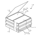
図9(a)において、符号60は第2の実施形態の固定手段としての固定部材である。固定部材60は、電極群10の一方の端面の略全体を覆う第1部分61と、第1部分61の一方の端辺から延設して電極群10の一方の側面を覆う第2部分62と、第1部分61の他の端辺から延設して電極群10の他方の側面を覆う第2部分63と、からなる。固定部材60が電極群10と接する片側の面は粘着層(図示せず)に覆われた粘着面となっている。
In FIG. 9A, reference numeral 60 denotes a fixing member as fixing means of the second embodiment. The fixing member 60 includes a
固定部材60は、図9(b)に示すように、電極部10の端面を覆う第1部分61と、第1部分61の2つの端辺からそれぞれ延設して電極群10の対向する側面を覆う、第2部分62と第2部分63とによって構成される。
As illustrated in FIG. 9B, the fixing member 60 includes a
第1部分61は、正極板11と負極板16とによる複数の層における対向形状と略同じ大きさであり、形状も正極部13と負極部18とに合わせて、この例では四角形である。
The
また、第1部分61の一方の端辺61aの任意の場所(図9に示す例では、短辺61aの中央付近)から延設して帯形状の第2部分62が形成されている。また、第1部分61の他方の端辺61bの任意の場所(図9に示す例では、短辺61bの中央付近)から延設して帯形状の第2部分63が形成されている。
Further, a band-shaped
説明に用いている例では、電極板を構成する電極部が平面視で四角形であるから、固定部材60の一方の端辺61aと他方の端辺61bとは対向しており、それ故に、第2部分62と第2部分63とは、平面視で第1部分61を挟んで対向して形成されている。
In the example used for the description, since the electrode part constituting the electrode plate is quadrangular in plan view, one end side 61a and the other end side 61b of the fixing member 60 are opposed to each other. The two
2つの第2部分62、63の長さLは、電極群10の高さH(図9(a)参照)に等しくするとよい。その理由は、第1の実施形態と同様である。
第2部分62、63の幅Wは、第1部分61の一辺より短く形成されており、図9に示
す例では、幅Wを一定としている。これによって、第2部分62、63は帯形状となっている。なお、第2部分62、63の幅Wが第1部分61の端辺よりも狭い理由も、第1の実施形態と同様である。
The length L of the two
The width W of the
第1部分61と第2部分62、63との繋がり部分には、それぞれ折り曲げ部62a、63aがある(点線で示す)。この折り曲げ部62a、63aを基準にして第2部分62、63を粘着面(図示せず)を内側にしてそれぞれ約90度近くまで折り曲げ、その状態で固定部材60を電極群10の端面と側面に接して電極群10を固定する。
There are bent portions 62a and 63a (indicated by dotted lines) at the connecting portions between the
以上のように、第2の実施形態によれば、固定部材60には対向する2つの第2部分62、63があり、電極群10の対向する2つの側面を覆うことができるので、電極群10の側面は、固定部材60によって確実に固着され、折り畳まれた正極板11と負極板16とがばらけたり、積層ずれをおこさないように固定される。
As described above, according to the second embodiment, the fixing member 60 has the two opposing
なお、固定部材60で固定された電極群10を電池ケースに組み込む工程は、第1の実施形態での組み込み工程(図5参照)と同様であるので説明は省略する。
In addition, since the process of incorporating the
[第2の実施形態の変形例1の構成説明:図10]
次に、第2の実施形態の変形例1の構成を、図10を用いて説明する。
第2の実施形態の変形例1は、第1部分の対向する2辺から延設した2つの第2部分を有する固定手段を、2つ有する構成である。
[Description of Configuration of
Next, the structure of the
The first modification of the second embodiment is a configuration having two fixing means having two second parts extending from two opposite sides of the first part.
図10において、符号70は第2の実施形態の変形例1の固定手段としての第1固定部材である。第1固定部材70は、電極群10の一方の端面の略半分を覆う第1部分71と、第1部分71の対向する端辺からそれぞれ延設して電極群10の対向する側面を覆う2つの第2部分72、73と、からなる。
In FIG. 10,
また、符号75は第2の実施形態の変形例1の固定手段としての第2固定部材である。第2固定部材75は、電極群10の一方の端面の略半分を覆う第1部分76と、第1部分76の対向する端辺からそれぞれ延設して電極群10の対向する側面を覆う2つの第2部分77、78と、からなる。
Reference numeral 75 denotes a second fixing member as fixing means of the first modification of the second embodiment. The second fixing member 75 includes a first portion 76 that covers substantially half of one end face of the
第1固定部材70と第2固定部材75とのそれぞれの第1部分71、76を合わせた平面視の大きさは、電極群10の正極板11と負極板16による複数の層における対向形状と略同じ大きさである。また、2つの第1部分71と第1部分76とは、厚み方向で重なることがないようにその大きさが規定されており、電極群10の端面において双方は若干の距離を離間して固定されている。
The size in plan view of the first portions 71 and 76 of the first fixing
第1固定部材70及び第2固定部材75のそれぞれの第2部分72、73及び第2部分77、78は、電極群10の対向する側面をそれぞれ2箇所で覆うので、電極群10は、より積層ずれを起こしにくくなる。
Since the second portions 72 and 73 and the
[固定部材を電極群の上下から固定する例の説明:図11]
以上説明した第1の実施形態と第2の実施形態は、固定部材を電極群の一方の端面(図面上では上側の端面)から側面を覆うように固定する例と、そのような固定部材を2つ設ける例を説明した。
もちろん、それらの例に限定せず、2つの固定部材を用い、電極群の一方の端面と他方の端面(図面上では下側の端面)との両方を固定するようにしてもよい。その例を、図11を用いて説明する。
[Description of an example of fixing the fixing member from above and below the electrode group: FIG. 11]
In the first and second embodiments described above, an example in which the fixing member is fixed so as to cover the side surface from one end surface (the upper end surface in the drawing) of the electrode group, and such a fixing member is provided. The example which provides two was demonstrated.
Of course, the present invention is not limited to these examples, and two fixing members may be used to fix both one end surface and the other end surface (the lower end surface in the drawing) of the electrode group. An example thereof will be described with reference to FIG.
図11において、符号90aは第1の実施形態の固定手段20(図3参照)と同様な形状を有する第1固定部材である。第1固定部材90aは、電極群10の図面上の上面の端面を覆う第1部分91aと、第1部分91aの端辺から延設して電極群10の側面を覆う第2部分92aと、からなる。
In FIG. 11, reference numeral 90a denotes a first fixing member having the same shape as the fixing means 20 (see FIG. 3) of the first embodiment. The first fixing member 90a includes a first portion 91a that covers the end surface of the upper surface of the
同様に、符号90bも第1の実施形態の固定手段20と同様な形状を有する第2固定部材である。第2固定部材90bは、電極群10の図面上の下面の端面を覆う第1部分91bと、第1部分91bの端辺から延設して電極群10の他の側面を覆う第2部分92bと、からなる。
Similarly, reference numeral 90b is a second fixing member having the same shape as the fixing means 20 of the first embodiment. The second fixing member 90b includes a first portion 91b that covers the end surface of the lower surface of the
このように、第1固定部材90aと第2固定部材90bとは、電極群10の両端面(図面上の上面と下面)を覆うように設けている。また、第1固定部材90aの第2部分92aと第2固定部材90bの第2部分92bは、電極群10の別の側面をそれぞれ覆っている。
Thus, the 1st fixing member 90a and the 2nd fixing member 90b are provided so that the both end surfaces (upper surface and lower surface on drawing) of the
なお、図11では、一例として第2部分92aと第2部分92bとは、電極群10の隣接する側面をそれぞれ覆っている。つまり、平面的に第1固定部材90aと第2固定部材90bとを90度ずらしているが、もちろんこの配置に限定されず、図示しないが、電極群10の対向する側面を覆ってもよい。
In FIG. 11, as an example, the second portion 92 a and the second portion 92 b cover adjacent side surfaces of the
また、電極群10を構成する正極板11の接続タブ部12は、電極群10の上面の端面を覆う第1固定部材90aの第1部分91aの上側の最上部に位置する。また同様に、電極群10を構成する負極板16の接続タブ部17は、電極群10の下面の端面を覆う第2固定部材90bの第1部分91bの下側の最下部に位置する。
Further, the connection tab portion 12 of the
この構成により、第1固定部材90aと第2固定部材90bによって固定された電極群10が、電池ケースに収納された場合(図5参照)、接続タブ部12と接続タブ部17は、それぞれ電池ケースの正極缶2と負極缶3に接することができるので、電気的な接続が可能となる。
With this configuration, when the
[第3の実施形態の構成説明:図12]
次に、第3の実施形態の扁平型電池の電極群及び固定部材の構成を、図12を用いて説明する。
図12(a)は第3の実施形態の電極群の斜視図であり、図12(b)は図12(a)の切断線C−C´による断面図である。なお、図12(b)の断面図は接続タブ部12、17を省略している。
[Description of Configuration of Third Embodiment: FIG. 12]
Next, the structure of the electrode group and fixing member of the flat battery according to the third embodiment will be described with reference to FIG.
FIG. 12A is a perspective view of the electrode group of the third embodiment, and FIG. 12B is a cross-sectional view taken along the section line CC ′ of FIG. In addition, the
図12において、符号80は第3の実施形態の固定手段としての固定部材である。固定部材80は、電極群10の一方の端面の略全体を覆う第1部分81と、第1部分81の端辺から延設して電極群10の側面を覆う第2部分82と、第2部分82の端部に電極群10の他方の端面を覆う折り返し部となる第3部分83とを有している。
In FIG. 12, reference numeral 80 denotes a fixing member as fixing means of the third embodiment. The fixing member 80 includes a
すなわち、固定部材80は、第2部分82の端部に、その先端部分を折り返す折り返し部となる第3部分83を設けている点が、すでに説明した実施形態と異なる点である。
第3部分83は、この例では、第1部分81と同じ面積で形成している。この形状の詳細は後述するが、固定部材80は、この形状により、電極群10の両端面(図面上の上面と下面)を挟み込むようにして固定することができる。
That is, the fixing member 80 is different from the embodiment described above in that a third portion 83 is provided at the end portion of the second portion 82 as a folded portion that folds the tip portion.
In this example, the third portion 83 is formed with the same area as the
また、電極群10を構成する正極板11の接続タブ部12は、電極群10の上面の端面を覆う固定部材80の第1部分81の上側の最上部に位置する。また同様に、電極群10
を構成する負極板16の接続タブ部17は、電極群10の下面の端面を覆う固定部材80の第3部分83の下側の最下部に位置する。
Further, the connection tab portion 12 of the
The connecting
この構成により、固定部材80によって固定された電極群10が、電池ケースに収納された場合(図5参照)、接続タブ部12と接続タブ部17は、それぞれ電池ケースの正極缶2と負極缶3に接することができるので、電気的な接続が可能となる。
With this configuration, when the
[第3の実施形態の固定部材の説明:図13]
次に、第3の実施形態の固定部材の詳細構造を、図13を用いて説明する。
図13(a)は第3の実施形態の固定部材の平面図であり、図13(b)は固定部材を折り曲げた状態の斜視図である。
[Description of Fixing Member of Third Embodiment: FIG. 13]
Next, the detailed structure of the fixing member of the third embodiment will be described with reference to FIG.
FIG. 13A is a plan view of the fixing member of the third embodiment, and FIG. 13B is a perspective view of the fixing member in a folded state.
図13(a)において、固定部材80は、前述したように、電極部10の一方の端面を覆う第1部分81と、第1部分81の端辺から延設して電極群10の側面を覆う第2部分82と、第2部分82の端部に電極群10の他方の端面を覆う第3部分83と、によって構成される。固定部材80が電極群10と接する片側の面は粘着層(図示せず)に覆われた粘着面となっている。
In FIG. 13A, as described above, the fixing member 80 includes the
第1部分81と第3部分83とは、正極板11と負極板16による複数の層における対向形状と同じ大きさであり、形状も正極部13と負極部18に合わせて、この例では四角形である。
The
第1部分81の端辺81aから延設して帯形状の第2部分82が形成されている。第2部分82の端部には、第3部分83が設けてあり、この例では第2部分82と一体となって形成されている。第2部分82は、後述するようにその幅Wが一定な帯形状であるので、3第1部分81の端辺81aと第3部分83の端辺83aとは、平面視では平行している。
A band-shaped second portion 82 is formed extending from the end side 81 a of the
第2部分82の長さLは、電極群10の高さH(図12参照)に略等しくするとよい。これは、第2部分82の両端に形成される第1部分81と第3部分83とによって、電極群10の両端面を挟み込むようにして固定するために、第2部分82の長さLと電極群10の高さHが略等しいと好都合だからである。
The length L of the second portion 82 is preferably substantially equal to the height H of the electrode group 10 (see FIG. 12). This is because the
すなわち、第2部分82の長さLが短いと、第1部分81と第1部分83とによって電極群10を挟み込むことが困難になり、また、第2部分82の長さLが長すぎると、第2部分82が電極群10の側面から離れて、側面を固定できなくなるためである。
That is, if the length L of the second portion 82 is short, it becomes difficult to sandwich the
また、第2部分82の幅Wは、第1部分81の端辺より短く形成され、これによって、第2部分82は帯形状となる。図示した例では、第2部分82の幅Wは一定である。第2部分82の幅Wが短く形成される理由は、第1の実施形態と同様である。
Further, the width W of the second portion 82 is formed shorter than the end side of the
また、第1部分81と第2部分82の繋がり部分には、折り曲げ部82a(点線で示す)があり、第2部分82と第3部分83との繋がり部分には、折り曲げ部82b(点線で示す)がある。
The connecting portion between the
この2つの折り曲げ部82a、82bを基準にして粘着面(図示せず)を内側にして第1部分81と第3部分83とをそれぞれ約90度近くまで折り曲げ、第1部分81と第3部分83とが、平行となる状態にしてから、電極群10の両端面を挟み込むように覆い固定する。
The
その様子を示すのが図13(b)である。図示するように、折り曲げ部82a、82bを基準にして第1部分81と第3部分83とを矢印F1、F2の方向へ折り曲げた状態の固定部材80を示している。
なお、折り曲げ作業は、第1部分81又は第3部分83のいずれかを電極群10の端面に固着したあとに実施するか、第2部分82を電極群10の側面に固着した後、同時に第1部分81と第3部分83とを折り曲げてもよい。
This is shown in FIG. 13 (b). As shown in the figure, the fixing member 80 is shown in a state in which the
The bending operation is performed after either the
また、固定部材80は、図13(b)に示すように、第1部分81と第3部分83とが折れ曲がって平行になっている状態の非金属によるクリップでもよい。クリップ状の固定部材80であれば、折り曲げ作業が不要であり、平行に形成された第1部分81と第3部分83との間に電極群10を差し込むことで、電極群10を簡単に固定することができる。
The fixing member 80 may be a non-metallic clip in which the
もちろん、固定部材80をクリップ形状とするとき、第1部分81と第3部分83とが平行となっていなくてもよい。すなわち、第1部分81において、第2部分82との繋がり部分がない側の短辺81bと、第3部分83において、第2部分82との繋がり部分がない側の端辺83bと、の対向距離が、図12に示す電極群10の高さHよりも若干小さくなるように、第1部分81と第3部分83とを傾斜させて曲げるのである。
Of course, when the fixing member 80 has a clip shape, the
そうすると、電極群10に固定部材80を差し込むときに、固定部材80の第1部分81と第3部分83とを押し広げるようにすれば、押し込みが終わると電極群10を第1部分81と第3部分83とで付勢するようになり、より強固に固定することができる。
Then, when the fixing member 80 is inserted into the
以上のように、第3の実施形態によれば、固定部材80により電極群10の上下両方の端面を挟むように固定することができるので、電極群10は、固定部材80によって確実に固着され、正極板11と負極板16とが離間しないように固定される。
As described above, according to the third embodiment, since the fixing member 80 can fix both the upper and lower end surfaces of the
なお、固定部材80で固定された電極群10を電池ケースに組み込む工程は、第1の実施形態での組み込み工程(図5参照)と同様であるので説明は省略する。
The process of incorporating the
[第3の実施形態の変形例の構成説明:図14、図15]
次に、第3の実施形態の変形例の構成を、図14及び図15を用いて説明する。
第3の実施形態の変形例は、すでに説明した第3実施形態(図12及び図13参照)の第2部分の端部に設ける折り返し部となる第3部分を小型化した例である。具体的には、固定部材の第2部分の長さを電極群の高さより長くして折り返し部を設け、この折り返し部によって電極群の他方の端面の一部を覆う構成である。
[Description of Configuration of Modified Example of Third Embodiment: FIGS. 14 and 15]
Next, a configuration of a modification of the third embodiment will be described with reference to FIGS. 14 and 15.
The modified example of the third embodiment is an example in which the third portion serving as the folded portion provided at the end portion of the second portion of the third embodiment (see FIGS. 12 and 13) already described is downsized. Specifically, the length of the second portion of the fixing member is made longer than the height of the electrode group to provide a folded portion, and this folded portion covers a part of the other end surface of the electrode group.
すでに説明した従来技術のように、電極群の端面が平坦でないと、金属ケースに電極群を搭載する作業において、金属ケースに掛る圧力により、電極群を形成する電極板同士の対向面が不均一になるなどの不具合を生じる。第3実施形態(図12及び図13参照)は、電極群の下部側の端面を固定する第3部分が、その端面と略同じ大きさであるため、電極群を形成する電極板同士の対向面は不均一にならない。 If the end face of the electrode group is not flat as in the prior art described above, the opposing surfaces of the electrode plates forming the electrode group are not uniform due to the pressure applied to the metal case in the work of mounting the electrode group on the metal case. This causes problems such as becoming. In the third embodiment (see FIGS. 12 and 13), since the third portion for fixing the lower end surface of the electrode group is substantially the same size as the end surface, the electrode plates forming the electrode group are opposed to each other. The surface will not be uneven.
この第3の実施形態の変形例は、電極群の下側の端面に固定部材95の折り返し部97a、98aが回り込む形態である点は第3の実施形態と同じであるが、この折り返し部97a、98aは、第3実施形態の第3部分よりも面積が小さい。
しかしながら、第3の実施形態の変形例は、従来技術のように電極群を形成する電極板同士の対向面が不均一になるようなことはなく、電極群の端面を平坦にすることができる。以下詳述する。
The modification of the third embodiment is the same as the third embodiment in that the folded portions 97a and 98a of the fixing member 95 wrap around the lower end face of the electrode group, but the folded portion 97a. 98a has a smaller area than the third portion of the third embodiment.
However, in the modification of the third embodiment, the opposing surfaces of the electrode plates forming the electrode group do not become non-uniform as in the prior art, and the end face of the electrode group can be flattened. . This will be described in detail below.
図14(a)は第3の実施形態の変形例の固定部材の平面図であり、図14(b)は
第3の実施形態の変形例の固定部材の斜視図である。また、図15(a)は第3の実施形態の変形例の固定部材で覆われた電極群の断面図であり、図15(b)は第3の実施形態の変形例の固定部材で覆われた電極群の他の例の断面図である。
FIG. 14A is a plan view of a fixing member according to a modification of the third embodiment, and FIG. 14B is a perspective view of a fixing member according to a modification of the third embodiment. FIG. 15A is a cross-sectional view of an electrode group covered with a fixing member according to a modification of the third embodiment, and FIG. 15B is covered with a fixing member according to a modification of the third embodiment. It is sectional drawing of the other example of the broken electrode group.
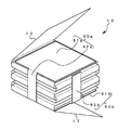
図14(a)において、符号95は第3の実施形態の変形例の固定手段としての固定部材である。固定部材95は、電極群10の一方の端面の略全体を覆う第1部分96と、第1部分96の端辺から延設して電極群10の一方の側面を覆う第2部分97と、第1部分96の他の端辺から延設して電極群10の他方の側面を覆う第2部分98と、からなる。第2部分97、98の端部には、折り返し部97a、98aがそれぞれ設けてある。
In FIG. 14A, reference numeral 95 denotes a fixing member as fixing means of a modification of the third embodiment. The fixing member 95 includes a
この折り返し部97a、98aが、図12及び図13を用いて説明した第3の実施形態の第3部分83に相当する。 The folded portions 97a and 98a correspond to the third portion 83 of the third embodiment described with reference to FIGS.
固定部材95の第1部分96の平面視の大きさは、電極群10の正極板11と負極板16とによる複数の層における対向形状と略同じ大きさであり、形状も正極部13、負極部18に合わせて、この例では四角形である。
The size of the
第1部分96から延設する2つの第2部分97、98の長さL´は、電極群10の高さH(図15(a)参照)より所定の長さだけ長く形成されている。この所定の長さは、折り返し部97a、98aの折り返し距離により決まる。すなわち、電極群10の高さHより長い領域が折り返し部97a、98aとなる。
The length L ′ of the two
第3の実施形態の変形例は、この第2部分97、98の折り返し部97a、98aを、第1部分96で覆われた電極群10の一方の端面に対面する他方の端面、すなわち、正極板11又は負極板16の他方の端面の角で折り返して、その端面に接して覆うのである。
In the modified example of the third embodiment, the folded portions 97a and 98a of the
図14(b)は、固定部材95の第2部分97、98の折り返し部97a、98aが、どのように折り返されるかを示している。すなわち、2つの第2部分97、98を第1部分96に対して、約90度近くまで折り曲げた後、折り返し部97a、98aをそれぞれ内側に向き合わせて折り返すのである。このときの折り返し角度は、約90度である。
FIG. 14B shows how the folded portions 97 a and 98 a of the
実際の折り曲げ作業は、図示しないが、固定部材95の第1部分96を電極群10の一方の端面に固定してから、2つの第2部分97、98を側面に沿って折り曲げ、さらに折り返し部97a、98aを他方の端面に折り返すとよい。このようにして、2つの第2部分97、98と折り返し部97a、98aとを折り曲げ折り返すことで、電極群10の上下の端面を挟み込むようにして固定することができる。
Although the actual bending operation is not shown, the
次に、第3の実施形態の変形例の固定部材がどのようにして電極群を固定するかを、図15の断面図を用いて説明する。
なお、図15では、電極群10の正極板11の接続タブ部12は、第1部分96の上側の電極群10の最上部に位置するが図示を省略している。また、負極板16の接続タブ部17は、電極群10の他方の端面10c(電極群10の図面上の最下部)に配置されている。この接続タブ部17は、前述したように、金属箔16pが露出しているので、電極群10の他方の端面10cは、接続タブ部17である金属箔16pが露出した状態である。
Next, how the fixing member of the modification of the third embodiment fixes the electrode group will be described with reference to the cross-sectional view of FIG.
In FIG. 15, the connection tab portion 12 of the
図15(a)において、固定部材95の第1部分96は、電極群10の一方の端面10a(図面上の上側)に固着し覆っている。また、固定部材95の2つの第2部分97、98は、電極群10の対向する側面に固着し覆っている。さらに、2つの第2部分97、98のそれぞれの折り返し部97a、98aは、電極群10の他方の端面10c(すなわち
、接続タブ部17)の角で折り返され、端面10cに接してその一部を覆っている。
In FIG. 15A, the
すなわち、2つの第2部分97、98のそれぞれの折り返し部97a、98aは、接続タブ部17を内側にして折り返し、接続タブ部17の一部分を覆っている。これにより、電極群10の端面10cは、接続タブ部17の表面に、折り返し部97a、98aが重なる領域が存在する。そして、この領域においては、折り返し部97a、98aの厚み分だけ厚くなるので凸領域となる。
That is, the folded portions 97 a and 98 a of the two
しかし、図15(a)で示す例では、電極群10を構成する正極板11の正極部13と負極板16の負極部18は、平面視で電極群10の外形より小さい面積で形成されているため、電極群10の外形から正極部13と負極部18までには、電極群10の内側周辺に図示するように隙間Sが存在する。
However, in the example shown in FIG. 15A, the positive electrode portion 13 of the
そして、この隙間Sの領域に2つの第2部分97、98のそれぞれの折り返し部97a、98aが配置されているので、この折り返し部97a、98aは、正極部13と負極部18とが積層された重なり領域には入らないように配置される。
Since the folded portions 97a and 98a of the two
この隙間Sは、電極板を構成する電極部(つまり、活物質層がある部分)ではなく、金属箔からなる接続部の部分であるから、前述したように、折り返し部97a、98aが、正極部13と負極部18とが重なり合っていない隙間Sの領域のみに配置されるならば、折り返し部97a、98aの厚みによって凸領域ができたとしても、その凸領域は隙間Sの範囲に限定されるので、正極部13と負極部18とに均一でない大きな圧力が加わることを防ぐことができる。
Since the gap S is not an electrode portion constituting the electrode plate (that is, a portion having an active material layer) but a connecting portion made of a metal foil, the folded portions 97a and 98a are connected to the positive electrode as described above. If the portion 13 and the
このため、電極群10の端面10cが2つの第2部分97、98のそれぞれの折り返し部97a、98aで覆われたとしても、電極群10の正極部13と負極部18との対向状態は平行平面を保つことができ、その結果、電極部に歪みや段差などが発生せず、信頼性の高い扁平型電池を提供できる。
For this reason, even if the end surface 10c of the
ところで、電極群の大きさは、求める電池の性能やサイズにより決めることができるが、電池容量を増やしたいなどの理由から、電極板を構成する電極部をより大きくしたい場合がある。そのようなときは、図15(a)に示す電極群10の外形から正極部13と負極部18とが重なる部分までの隙間Sは、ほとんど存在しなくなる。
By the way, although the size of the electrode group can be determined by the required battery performance and size, there are cases in which it is desired to make the electrode portion constituting the electrode plate larger for reasons such as increasing the battery capacity. In such a case, there is almost no gap S from the outer shape of the
そうすると、固定部材95を構成する第2部分97、98のそれぞれの折り返し部97a、98aは、上述の例とは異なり、電極群の電極部が対向する領域と平面的に重なってしまう(図15(b)の領域V)。
Then, unlike the above-described example, the folded portions 97a and 98a of the
そのような領域Vが発生しても、図15(b)に示すように、電極群10の端面10cにおいて、折り返し部97a、98aがない領域に、図示するように、折り返し部97a、98aの厚みと等しい厚みの導電性のスペーサ99を設ければよい。このようにすることで、折り返し部97a、98aがあっても端面10c全体を平坦化することができる。
Even if such a region V occurs, as shown in FIG. 15B, in the end surface 10c of the
スペーサ99は、例えば、公知の導電性フィルムで構成することができる。この導電性フィルムは、特に限定するものではないが、ポリエステルを主成分とする基材の一方の面に多数の金属粒子を含有するなどした導電性アクリル系粘着剤を塗布した構造である。
The
このようなスペーサ99は、電極群10の端面10c(すなわち、接続タブ部17)と、電極群10が電池ケースに収納されたとき、その電池ケース(例えば、負極缶3:図5参照)と、を電気的に接続する接続部材としても機能し、電極群10と電池ケースを電気
的に接続することができる。
Such a
このスペーサ99を端面10cに貼ることで、電極群10が電池ケースに組み込まれて圧縮されても、電極群10の端面10c全域が平坦なので、正極板11の正極部13と負極板16の負極部18とには均一の圧力が加わり、電極群10の正極部13と負極部18との対向状態は平行平面に保つことができ、電極部に歪みや段差などが発生せず、信頼性の高い扁平型電池を提供できる。
By sticking this
また、第3の実施形態の変形例の固定部材95も第3の実施形態と同様に、第2部分97、98と折り返し部97a、98aとが第1部分96からそれぞれ折り曲がった状態の非金属によるクリップとしてもよい。
Further, the fixing member 95 according to the modified example of the third embodiment is similar to the third embodiment in that the
クリップ状の固定部材95であれば、折り曲げ作業が不要であり、第1部分96と折り返し部97a、98aとの間に電極群10を差し込むことで、電極群10を簡単に固定することができる。
If the clip-shaped fixing member 95 is used, the bending operation is not necessary, and the
以上、本発明の扁平型電池の3つの実施形態を説明した。本発明はそれらの実施形態に限定されるものではなく、本発明の要旨を満たすものであれば、任意に変更してよい。 The three embodiments of the flat battery of the present invention have been described above. The present invention is not limited to these embodiments, and may be arbitrarily changed as long as the gist of the present invention is satisfied.
1 扁平型電池
2 正極缶
3 負極缶
4 ガスケット
10 電極群
11 正極板
12、17 接続タブ部
13 正極部
16 負極板
18 負極部
20、50、60、80、95 固定部材
21、31、36、41、46、51、61、71、76、81、83、91a、91b、96 第1部分
22、32、37、42、47、52、53、62、63、72、73、77、78、82、92a、92b、97、98 第2部分
30、40、70、90a 第1固定部材
35、45、75、90b 第2固定部材
97a、98a 折り返し部
99 スペーサ
DESCRIPTION OF
Claims (4)
前記正極板と前記負極板とが対向するように複数の層を形成して、収納体に内包した扁平型電池において、
前記正極板又は前記負極板の端面と、前記複数の層の側面と、を覆い前記正極板と前記負極板とが離間しないように固定する固定手段を設け、
前記固定手段は、前記端面を覆う第1部分と、前記第1部分の端辺から延設して前記側面を覆う第2部分と、からなる
ことを特徴とする扁平型電池。 Having a positive electrode plate and a negative electrode plate with an active material layer formed on the surface of the metal foil,
In the flat battery in which a plurality of layers are formed so that the positive electrode plate and the negative electrode plate face each other,
Providing a fixing means for covering the end face of the positive electrode plate or the negative electrode plate and the side surfaces of the plurality of layers so that the positive electrode plate and the negative electrode plate are not separated from each other;
The flat battery is characterized in that the fixing means includes a first portion that covers the end surface, and a second portion that extends from the end side of the first portion and covers the side surface.
ことを特徴とする請求項1に記載の扁平型電池。 2. The flat battery according to claim 1, wherein the first portion has substantially the same size as a facing shape in the plurality of layers.
ことを特徴とする請求項1又は2に記載の扁平型電池。 The flat battery according to claim 1 or 2, wherein the second portion has a smaller area than the first portion.
前記折り返し部は、前記正極板又は前記負極板の他の端面と接する
ことを特徴とする請求項1から3のいずれか1つに記載の扁平型電池。 The second portion has a folded portion at an end thereof,
The flat battery according to any one of claims 1 to 3, wherein the folded portion is in contact with the other end face of the positive electrode plate or the negative electrode plate.
Priority Applications (1)
| Application Number | Priority Date | Filing Date | Title |
|---|---|---|---|
| JP2014247770A JP2016110856A (en) | 2014-12-08 | 2014-12-08 | Flat battery |
Applications Claiming Priority (1)
| Application Number | Priority Date | Filing Date | Title |
|---|---|---|---|
| JP2014247770A JP2016110856A (en) | 2014-12-08 | 2014-12-08 | Flat battery |
Publications (1)
| Publication Number | Publication Date |
|---|---|
| JP2016110856A true JP2016110856A (en) | 2016-06-20 |
Family
ID=56122222
Family Applications (1)
| Application Number | Title | Priority Date | Filing Date |
|---|---|---|---|
| JP2014247770A Pending JP2016110856A (en) | 2014-12-08 | 2014-12-08 | Flat battery |
Country Status (1)
| Country | Link |
|---|---|
| JP (1) | JP2016110856A (en) |
Cited By (4)
| Publication number | Priority date | Publication date | Assignee | Title |
|---|---|---|---|---|
| JP2021061161A (en) * | 2019-10-07 | 2021-04-15 | セイコーインスツル株式会社 | Electrochemical cell |
| CN114171854A (en) * | 2020-09-11 | 2022-03-11 | 丰田自动车株式会社 | Battery module |
| JP2022534862A (en) * | 2019-06-04 | 2022-08-04 | レナタ・アーゲー | cell battery |
| JP2022145585A (en) * | 2021-03-18 | 2022-10-04 | 輝能科技股▲分▼有限公司 | Electrode assembly and battery device thereof |
-
2014
- 2014-12-08 JP JP2014247770A patent/JP2016110856A/en active Pending
Cited By (16)
| Publication number | Priority date | Publication date | Assignee | Title |
|---|---|---|---|---|
| US12531263B2 (en) | 2019-06-04 | 2026-01-20 | Renata Ag | Cell battery |
| JP2022534862A (en) * | 2019-06-04 | 2022-08-04 | レナタ・アーゲー | cell battery |
| JP7489406B2 (en) | 2019-06-04 | 2024-05-23 | レナタ・アーゲー | Cell battery |
| JP2021061161A (en) * | 2019-10-07 | 2021-04-15 | セイコーインスツル株式会社 | Electrochemical cell |
| JP7538293B2 (en) | 2019-10-07 | 2024-08-21 | セイコーインスツル株式会社 | Laminated electrode body |
| JP7304788B2 (en) | 2019-10-07 | 2023-07-07 | セイコーインスツル株式会社 | electrochemical cell |
| JP2023127589A (en) * | 2019-10-07 | 2023-09-13 | セイコーインスツル株式会社 | Laminated electrode body |
| JP2023160998A (en) * | 2020-09-11 | 2023-11-02 | トヨタ自動車株式会社 | Battery module manufacturing method |
| JP7354971B2 (en) | 2020-09-11 | 2023-10-03 | トヨタ自動車株式会社 | battery module |
| US11942592B2 (en) | 2020-09-11 | 2024-03-26 | Toyota Jidosha Kabushiki Kaisha | Battery module |
| JP2022047130A (en) * | 2020-09-11 | 2022-03-24 | トヨタ自動車株式会社 | Battery module |
| JP7601167B2 (en) | 2020-09-11 | 2024-12-17 | トヨタ自動車株式会社 | Battery module manufacturing method |
| US12315869B2 (en) | 2020-09-11 | 2025-05-27 | Toyota Jidosha Kabushiki Kaisha | Battery module |
| CN114171854A (en) * | 2020-09-11 | 2022-03-11 | 丰田自动车株式会社 | Battery module |
| JP7417647B2 (en) | 2021-03-18 | 2024-01-18 | 輝能科技股▲分▼有限公司 | Electrode assembly and its battery device |
| JP2022145585A (en) * | 2021-03-18 | 2022-10-04 | 輝能科技股▲分▼有限公司 | Electrode assembly and battery device thereof |
Similar Documents
| Publication | Publication Date | Title |
|---|---|---|
| JP5779828B2 (en) | Electrode assembly having step, battery cell, battery pack and device including the same | |
| JP6618677B2 (en) | Electrode assembly and secondary battery including the same | |
| JP5825436B2 (en) | ELECTRODE ASSEMBLY EXCELLENT IN ELECTRODE TAB CONNECTIVITY, BATTERY CELL CONTAINING THE SAME, DEVICE AND MANUFACTURING METHOD | |
| JP6884459B2 (en) | Electrode assembly and secondary battery equipped with it | |
| JP5943244B2 (en) | Electrode assembly having step, battery cell, battery pack and device including the same | |
| JP6735445B2 (en) | Wound battery | |
| KR102303827B1 (en) | Complex electrode assembly including a plurality of electrode assemblies and electrochemical device comprising the complex electrode assembly | |
| JP6169789B2 (en) | Curved electrode laminate and battery pack including the same | |
| JP5943243B2 (en) | Electrode assembly having step, battery cell, battery pack and device including the same | |
| KR101526457B1 (en) | Electrode Having Round Corner | |
| US10741820B2 (en) | Rechargeable battery | |
| KR20130118716A (en) | Electrode assembly, battery cell and device comprising the same | |
| JPWO2017010046A1 (en) | Winding battery | |
| CN108292730A (en) | Electrochemical device | |
| CN107851768A (en) | The manufacture method of electrochemical device | |
| KR102314631B1 (en) | Electrode-assembly | |
| JP2016115471A (en) | Flat battery | |
| JP2017050243A (en) | Flat-type battery | |
| JP2016110856A (en) | Flat battery | |
| US20150255775A1 (en) | Stepwise electrode assembly including one-sided negative electrode | |
| JP2016111020A (en) | Flat battery | |
| JP2016129095A (en) | Flat type battery | |
| US20220328940A1 (en) | Secondary battery | |
| JP2016076329A (en) | Flat type battery and manufacturing method for the same | |
| CN111193075B (en) | Electrochemical cell |