JP2016125478A - Air-fuel ratio control device for internal combustion engine - Google Patents
Air-fuel ratio control device for internal combustion engine Download PDFInfo
- Publication number
- JP2016125478A JP2016125478A JP2015002552A JP2015002552A JP2016125478A JP 2016125478 A JP2016125478 A JP 2016125478A JP 2015002552 A JP2015002552 A JP 2015002552A JP 2015002552 A JP2015002552 A JP 2015002552A JP 2016125478 A JP2016125478 A JP 2016125478A
- Authority
- JP
- Japan
- Prior art keywords
- air
- fuel ratio
- fuel
- way catalyst
- internal combustion
- Prior art date
- Legal status (The legal status is an assumption and is not a legal conclusion. Google has not performed a legal analysis and makes no representation as to the accuracy of the status listed.)
- Pending
Links
Images
Classifications
-
- Y—GENERAL TAGGING OF NEW TECHNOLOGICAL DEVELOPMENTS; GENERAL TAGGING OF CROSS-SECTIONAL TECHNOLOGIES SPANNING OVER SEVERAL SECTIONS OF THE IPC; TECHNICAL SUBJECTS COVERED BY FORMER USPC CROSS-REFERENCE ART COLLECTIONS [XRACs] AND DIGESTS
- Y02—TECHNOLOGIES OR APPLICATIONS FOR MITIGATION OR ADAPTATION AGAINST CLIMATE CHANGE
- Y02T—CLIMATE CHANGE MITIGATION TECHNOLOGIES RELATED TO TRANSPORTATION
- Y02T10/00—Road transport of goods or passengers
- Y02T10/10—Internal combustion engine [ICE] based vehicles
- Y02T10/12—Improving ICE efficiencies
-
- Y—GENERAL TAGGING OF NEW TECHNOLOGICAL DEVELOPMENTS; GENERAL TAGGING OF CROSS-SECTIONAL TECHNOLOGIES SPANNING OVER SEVERAL SECTIONS OF THE IPC; TECHNICAL SUBJECTS COVERED BY FORMER USPC CROSS-REFERENCE ART COLLECTIONS [XRACs] AND DIGESTS
- Y02—TECHNOLOGIES OR APPLICATIONS FOR MITIGATION OR ADAPTATION AGAINST CLIMATE CHANGE
- Y02T—CLIMATE CHANGE MITIGATION TECHNOLOGIES RELATED TO TRANSPORTATION
- Y02T10/00—Road transport of goods or passengers
- Y02T10/10—Internal combustion engine [ICE] based vehicles
- Y02T10/30—Use of alternative fuels, e.g. biofuels
Landscapes
- Electrical Control Of Air Or Fuel Supplied To Internal-Combustion Engine (AREA)
- Combined Controls Of Internal Combustion Engines (AREA)
- Exhaust Gas After Treatment (AREA)
- Output Control And Ontrol Of Special Type Engine (AREA)
Abstract
Description
本発明は、メタンを主成分とする燃料を使用して運転される内燃機関の空燃比制御装置に関する。 The present invention relates to an air-fuel ratio control apparatus for an internal combustion engine that is operated using a fuel mainly composed of methane.
従来、ガソリンを使用する内燃機関の空燃比制御装置として、三元触媒より下流の排気通路に配置された酸素濃度センサの出力信号に基づいて三元触媒より上流の排気通路に配置された空燃比センサの出力信号を補正し、その補正後の出力信号が目標空燃比に一致するように燃料噴射量をフィードバック制御するものにおいて、三元触媒が十分に活性していないときに、前記空燃比センサの出力目標値をリッチ側に移行させることで、三元触媒より下流に排出されるNOXの量を減少させようとする技術が提案されている(たとえば、特許文献1を参照)。 Conventionally, as an air-fuel ratio control device for an internal combustion engine using gasoline, an air-fuel ratio arranged in an exhaust passage upstream of the three-way catalyst based on an output signal of an oxygen concentration sensor arranged in the exhaust passage downstream of the three-way catalyst When the output signal of the sensor is corrected, and the fuel injection amount is feedback controlled so that the corrected output signal matches the target air-fuel ratio, the air-fuel ratio sensor is used when the three-way catalyst is not sufficiently activated. output target value by shifting to the rich side, techniques to try to reduce the amount of the NO X discharged from the three-way catalyst downstream has been proposed (e.g., see Patent Document 1).
本発明の目的は、メタンを主成分とする燃料を使用して運転され、その排気通路に三元触媒が配置される内燃機関の空燃比制御装置において、排気中に含まれるメタンを三元触媒によって好適に浄化することができる技術の提供にある。 An object of the present invention is an air-fuel ratio control apparatus for an internal combustion engine that is operated using a fuel mainly composed of methane and has a three-way catalyst disposed in an exhaust passage thereof. Therefore, the present invention provides a technique that can be suitably purified.
本発明は、上記した課題を解決するために、以下のような手段を採用した。すなわち、本発明は、メタンを主成分とする燃料を使用して運転され、その排気通路に三元触媒が配置される内燃機関の空燃比制御装置において、メタンを主成分とする燃料を内燃機関の吸気通路又は気筒内へ噴射するための燃料噴射弁と、前記三元触媒の温度を取得する取得手段と、前記取得手段により取得された温度に応じて、内燃機関で燃焼に供される混合気の目標空燃比を設定する設定手段と、前記設定手段により設定された目標空燃比に従って、前記燃料噴射弁を制御する制御手段と、を備え、前記三元触媒は該三元触媒の温度が低いときは高いときに比べメタンの浄化率が最大となる空燃比が低くなる特性を有し、前記設定手段は前記取得手段により取得された前記三元触媒の温度において前記三元触媒によるメタンの浄化率が最大となる空燃比を目標空燃比に設定するようにした。 The present invention employs the following means in order to solve the above-described problems. That is, the present invention relates to an air-fuel ratio control apparatus for an internal combustion engine that is operated using a fuel mainly composed of methane and has a three-way catalyst disposed in an exhaust passage thereof. A fuel injection valve for injecting into the intake passage or the cylinder, an acquisition means for acquiring the temperature of the three-way catalyst, and a mixture provided for combustion in the internal combustion engine according to the temperature acquired by the acquisition means Setting means for setting a target air-fuel ratio of air, and control means for controlling the fuel injection valve in accordance with the target air-fuel ratio set by the setting means, wherein the temperature of the three-way catalyst is When the temperature is low, the air-fuel ratio at which the purification rate of methane is maximized is lower than when it is high, and the setting means is configured to reduce the methane produced by the three-way catalyst at the temperature of the three-way catalyst obtained by the obtaining means. Purification rate The air-fuel ratio becomes larger and to set the target air-fuel ratio.
本発明によれば、メタンを主成分とする燃料を使用して運転され、その排気通路に三元触媒が配置される内燃機関の空燃比制御装置において、排気中に含まれるメタンを三元触媒によって好適に浄化することができる。 According to the present invention, in an air-fuel ratio control apparatus for an internal combustion engine that is operated using a fuel containing methane as a main component and a three-way catalyst is disposed in an exhaust passage thereof, the methane contained in the exhaust gas is three-way catalyst. Can be suitably purified.
以下、本発明の具体的な実施形態について図面に基づいて説明する。本実施形態に記載される構成部品の寸法、材質、形状、相対配置等は、特に記載がない限り発明の技術的範囲をそれらのみに限定する趣旨のものではない。 Hereinafter, specific embodiments of the present invention will be described with reference to the drawings. The dimensions, materials, shapes, relative arrangements, and the like of the components described in the present embodiment are not intended to limit the technical scope of the invention to those unless otherwise specified.
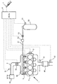
図1は、本発明を適用する内燃機関の概略構成を示す図である。図1に示す内燃機関1は、メタンを主成分とする圧縮天然ガス(CNG:Compressed Natural Gas)を使用して運転される火花点火式の内燃機関である。なお、図1に示す内燃機関1は4つの気筒2を有しているが、本発明を適用可能な内燃機関の気筒数は4つに限られるものではなく、3つ以下であってもよく、又は5つ以上であってもよい。
FIG. 1 is a diagram showing a schematic configuration of an internal combustion engine to which the present invention is applied. An
内燃機関1には、吸気管3と排気管4とが接続されている。吸気管3は、大気中から取り込まれた新気(空気)を各気筒2へ導くための通路である。吸気管3の途中には、エアクリーナ30が取り付けられている。エアクリーナ30は、空気中に含まれる塵や埃などを捕集するものである。エアクリーナ30より下流の吸気管3には、エアフローメータ31が取り付けられている。エアフローメータ31は、吸気管3を流れる空気の量(質量)に相関する電気信号を出力するものである。エアフローメータ31より下流の吸気管3には、スロットル弁32が取り付けられている。スロットル弁32は、吸気管3の通路断面積を変更することにより、内燃機関1へ供給される空気量を変更するものである。
An intake pipe 3 and an
なお、スロットル弁32より下流の吸気管3は、4つの枝管に分岐され、各枝管が一つの気筒2に接続されている。吸気管3の各枝管には、該枝管内にCNGを噴射するための燃料噴射弁5が取り付けられている。なお、燃料噴射弁5は、内燃機関1に取り付けられて、気筒2内へ直接CNGを噴射するように構成されてもよい。
The intake pipe 3 downstream of the
燃料噴射弁5は、デリバリパイプ50に接続されている。デリバリパイプ50は、燃料パイプ51を介して、ガスタンク52に接続されている。ガスタンク52は、CNGを貯蔵するためのタンクである。ガスタンク52に貯蔵されたCNGは、燃料パイプ51を介してデリバリパイプ50へ供給され、次いでデリバリパイプ50から4つの燃料噴射弁5に分配される。なお、燃料パイプ51の途中には、遮断弁53が配置される。遮断弁53は、燃料パイプ51の導通と遮断を切り替えるものであり、内燃機関1の運転停止中(たとえば、イグニッションスイッチがオフの期間)は閉弁し、内燃機関1の運転中(たとえば、イグニッションスイッチがオンの期間)は開弁する。遮断弁53としては、たとえば、駆動電力が印加されたときに開弁し、駆動電力が印加されないときは閉弁する電磁式の弁装置を用いることができる。
The
遮断弁53より下流の燃料パイプ51には、レギュレータ54が配置される。レギュレータ54は、ガスタンク52から供給されるCNGの圧力を予め設定された圧力(設定圧力)に減圧するものである。言い換えると、レギュレータ54は、該レギュレータ54より下流の燃料パイプ51における燃料圧力、言い換えれば燃料噴射弁5及びデリバリパイプ50に印加される燃料圧力(以下、「燃料噴射圧力」と称する)が設定圧力と等しくなるように、燃料パイプ51の通路断面積を調整する弁装置である。レギュレータ54としては、たとえば、ダイヤフラムとスプリングを組み合わせた機械式の弁装置を用いることができる。また、ガスタンク52には、圧力センサ55が取り付けられている。圧力センサ55は、ガスタンク52内の圧力に相関した電気信号を出力する。
A
排気管4は、各気筒2から排出される既燃ガス(排気)を排気浄化装置40や消音器などの経由させた後に大気中へ排出するための通路である。排気浄化装置40は、筒状のケーシング内に三元触媒を収容したものであり、排気中の炭化水素(HC)、一酸化炭素(
CO)、及び窒素酸化物(NOX)を浄化するための装置である。また、排気浄化装置40より上流の排気管4には、気筒2内で燃焼に供された混合気の空燃比に相関する電気信号を出力する空燃比センサ41が取り付けられている。また、排気浄化装置40より下流の排気管4には、排気の温度に相関する電気信号を出力する排気温度センサ42が取り付けられている。
The
CO), and a device for purifying nitrogen oxides (NO X). Further, an air-
このように構成された内燃機関1には、ECU(Electronic Control Unit)6が搭載
されている。ECU6は、CPU、ROM、RAM、バックアップRAMなどから構成される電子制御ユニットである。ECU6には、前述したエアフローメータ31、空燃比センサ41、排気温度センサ42、圧力センサ55に加え、アクセルポジションセンサ7やクランクポジションセンサ8等の各種センサが電気的に接続されている。
An ECU (Electronic Control Unit) 6 is mounted on the
アクセルポジションセンサ7は、アクセルペダルの操作量(アクセル開度)に相関する電気信号を出力するセンサである。クランクポジションセンサ8は、内燃機関1のクランクシャフトの回転位置に相関する電気信号を出力するセンサである。
The
また、ECU6には、燃料噴射弁5、スロットル弁32、及び遮断弁53等の各種機器が電気的に接続されている。ECU6は、前記した各種センサの出力信号に基づいて、前記各種機器を制御する。たとえば、ECU6は、前記した各種センサの出力信号に基づいて内燃機関1の運転条件(たとえば、機関負荷や機関回転速度等)を特定し、その運転条件に基づいて各気筒2で燃焼に供される混合気の目標空燃比を設定し、その目標空燃比とエアフローメータ31の出力信号(吸入空気量)とに基づいて燃料噴射弁5から噴射させるCNGの量(目標燃料噴射量)を演算する。そして、ECU6は、目標燃料噴射量に従って燃料噴射弁5を制御する。また、ECU6は、空燃比センサ41の出力信号が目標空燃比と一致するように、燃料噴射量をフィードバック制御する。
Various devices such as the
ここで、内燃機関の燃料としてガソリンや軽油等の液体燃料が使用される場合においては、排気中に含まれるメタンが少ない。そのため、三元触媒は、排気の空燃比が理論空燃比近傍の所定の範囲に属するときに、排気中の炭化水素(HC)、一酸化炭素(CO)、及び窒素酸化物(NOX)を効果的に浄化することができる。これに対し、内燃機関の燃料としてメタンを主成分とするCNGが使用される場合においては、排気中に含まれる炭化水素が主にメタンとなる。そして、三元触媒の温度が所定温度(窒素酸化物や一酸化炭素の転化率が80%以上になる温度であって、たとえば400℃)以上であるときは、三元触媒によるメタンの浄化率が最大となる空燃比は、三元触媒の温度に応じて変化する。 Here, when liquid fuel such as gasoline or light oil is used as the fuel for the internal combustion engine, the amount of methane contained in the exhaust gas is small. Therefore, the three-way catalyst when the air-fuel ratio of the exhaust gas is within a predetermined ratio of near stoichiometric air-fuel ratio, hydrocarbons in the exhaust gas (HC), carbon monoxide (CO), and nitrogen oxides (NO X) It can be effectively purified. On the other hand, when CNG mainly composed of methane is used as the fuel for the internal combustion engine, hydrocarbons contained in the exhaust gas are mainly methane. When the temperature of the three-way catalyst is equal to or higher than a predetermined temperature (the temperature at which the conversion rate of nitrogen oxides or carbon monoxide is 80% or more, for example, 400 ° C.), the methane purification rate by the three-way catalyst The air-fuel ratio at which the maximum value changes depends on the temperature of the three-way catalyst.
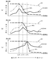
図2は、三元触媒へ流入する排気の空燃比と三元触媒による排気成分(炭化水素、一酸化炭素、及び窒素酸化物)の浄化率との関係を示す図である。なお、図2中の(a)は、三元触媒の温度が400℃であるときの関係を示す。また、図2中の(b)は、三元触媒の温度が600℃であるときの関係を示す。そして、図2中の(c)は、三元触媒の温度が800℃以上であるときの関係を示す。 FIG. 2 is a diagram showing the relationship between the air-fuel ratio of the exhaust gas flowing into the three-way catalyst and the purification rate of exhaust components (hydrocarbon, carbon monoxide, and nitrogen oxide) by the three-way catalyst. In addition, (a) in FIG. 2 shows a relationship when the temperature of a three-way catalyst is 400 degreeC. Moreover, (b) in FIG. 2 shows the relationship when the temperature of the three-way catalyst is 600 ° C. And (c) in FIG. 2 shows the relationship when the temperature of the three-way catalyst is 800 ° C. or higher.
図2中の(a)に示すように、三元触媒の温度が400℃であるときは、メタンを主成分とする炭化水素(図中のHC(CH4))の浄化率が最大となる排気の空燃比(図中のA/F1)は、理論空燃比(図中のA/Ft)より低いリッチな空燃比となる。そして、排気の空燃比が前記A/F1であるときは、一酸化炭素及び窒素酸化物の浄化率も十分に高くなる。 As shown in FIG. 2 (a), when the temperature of the three-way catalyst is 400 ° C., the purification rate of hydrocarbons mainly composed of methane (HC (CH 4 ) in the figure) becomes maximum. The air-fuel ratio (A / F1 in the figure) of the exhaust gas is a rich air-fuel ratio that is lower than the theoretical air-fuel ratio (A / Ft in the figure). When the air-fuel ratio of the exhaust gas is A / F1, the purification rate of carbon monoxide and nitrogen oxide is sufficiently high.
また、図2中の(b)に示すように、三元触媒の温度が600℃であるときは、メタンを主成分とする炭化水素の浄化率が最大となる空燃比(図中のA/F2)は、前記した400℃のときの空燃比A/F1より高く、且つ理論空燃比A/Ftより低いリッチな空燃
比となる。そして、排気の空燃比が前記A/F2であるときは、一酸化炭素及び窒素酸化物の浄化率も十分に高くなる。
Further, as shown in FIG. 2B, when the temperature of the three-way catalyst is 600 ° C., the air-fuel ratio (A / F2) is a rich air-fuel ratio that is higher than the air-fuel ratio A / F1 at 400 ° C. and lower than the stoichiometric air-fuel ratio A / Ft. When the air-fuel ratio of the exhaust gas is A / F2, the purification rate of carbon monoxide and nitrogen oxide is sufficiently high.
さらに、図2中の(c)に示すように、三元触媒の温度が800℃以上の高温であるときは、メタンを主成分とする炭化水素の浄化率が最大となる空燃比は、理論空燃比A/Ftに近似する。そして、排気の空燃比が理論空燃比A/Ftに近似しているときは、一酸化炭素及び窒素酸化物の浄化率も十分に高くなる。 Further, as shown in FIG. 2 (c), when the temperature of the three-way catalyst is a high temperature of 800 ° C. or higher, the air-fuel ratio at which the purification rate of hydrocarbons mainly composed of methane is maximized is It approximates to the air-fuel ratio A / Ft. When the air-fuel ratio of the exhaust is close to the stoichiometric air-fuel ratio A / Ft, the purification rate of carbon monoxide and nitrogen oxide is sufficiently high.
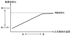
上記したような三元触媒の特性を考慮すると、三元触媒へ流入する排気の空燃比を、メタンを主成分とする炭化水素の浄化率が最大となる空燃比(以下、「最適空燃比」と記す)に制御することができれば、メタンを主成分とする炭化水素の浄化率を最大にすることができるとともに、一酸化炭素及び窒素酸化物の浄化率も十分に高めることができる。そこで、本実施例では、三元触媒の温度と最適空燃比との関係を予め実験的に求めておき、それらの関係をマップ又は関数式の態様でECU6のROMに記憶させておくようにした。具体的には、図3に示すように、三元触媒の温度が低いときは高いときに比べ、最適空燃比が低くなるようなマップ又は関数式をECU6のROMに記憶させておくものとする。そして、ECU6は、三元触媒の温度を引数として前記マップ又は前記関数式にアクセスすることで、最適空燃比を求め、その最適空燃比を目標空燃比に設定する。このように、内燃機関1の気筒2内で燃焼に供される混合気の目標空燃比が設定されると、三元触媒へ流入する排気の空燃比が該三元触媒の温度に応じた最適空燃比になるため、三元触媒によるメタンの浄化率を最大にしつつ、一酸化炭素及び窒素酸化物の浄化率を十分に高めることができる。
Considering the characteristics of the three-way catalyst as described above, the air-fuel ratio of the exhaust gas flowing into the three-way catalyst is defined as the air-fuel ratio (hereinafter referred to as “optimum air-fuel ratio”) that maximizes the purification rate of hydrocarbons mainly composed of methane. Can be maximized, and the purification rate of carbon monoxide and nitrogen oxides can be sufficiently increased. Therefore, in this embodiment, the relationship between the temperature of the three-way catalyst and the optimum air-fuel ratio is experimentally obtained in advance, and the relationship is stored in the ROM of the
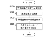
以下、内燃機関1の気筒2内で燃焼に供される混合気の空燃比を制御する手順について図4に沿って説明する。図4は、三元触媒の温度が前記所定温度以上であるときに、ECU6が所定の周期で繰り返し実行する処理ルーチンを示すフローチャートである。この処理ルーチンは、予めECU6のROMに記憶されているものとする。
Hereinafter, the procedure for controlling the air-fuel ratio of the air-fuel mixture used for combustion in the
図4の処理ルーチンでは、ECU6は、先ずS101の処理において、三元触媒の温度Tcatを取得する。ここで、三元触媒の温度は、該三元触媒に温度センサを取り付けることで直接測定されてもよく、内燃機関1の運転状態又は排気温度センサ42の測定値から推定されてもよい。なお、ECU6がS101の処理を実行することにより、本発明に係わる取得手段が実現される。
In the processing routine of FIG. 4, the
S102の処理では、ECU6は、前記S101の処理で取得された三元触媒の温度Tcatを引数として、前述した図3に示したような関係を規定したマップ又は関数式にアクセスし、前記温度Tcatに対応した最適空燃比を演算する。続いて、ECU6は、S103の処理へ進み、前記S102の処理で算出された最適空燃比を目標空燃比に設定する。このようにECU6がS102及びS103の処理を実行することにより、本発明に係わる設定手段が実現される。
In the process of S102, the
S104の処理では、ECU6は、前記S103の処理で設定された目標空燃比に従って燃料噴射弁5を制御する。詳細には、ECU6は、エアフローメータ31の出力信号(吸入空気量)を前記目標空燃比で除算することで目標燃料噴射量を算出し、その算出された目標燃料噴射量に従って燃料噴射弁5の開弁時間を制御する。さらに、ECU6は、空燃比センサ41の出力信号と前記目標空燃比との差に基づいて目標燃料噴射量を補正する制御(空燃比フィードバック制御)も実行する。このようにECU6がS104の処理を実行することにより、本発明に係わる制御手段が実現される。
In the process of S104, the
以上述べた実施例によれば、三元触媒における一酸化炭素及び窒素酸化物の浄化率を高
く保ちつつ、三元触媒におけるメタンの浄化率を最大限に高めることができる。その結果、メタンを主成分とする燃料を使用する内燃機関において、排気浄化装置40より下流へ排出される一酸化炭素及び窒素酸化物の量を少なく抑えつつ、メタンの量も最小限に抑えることができる。
According to the embodiment described above, the purification rate of methane in the three-way catalyst can be maximized while the purification rate of carbon monoxide and nitrogen oxides in the three-way catalyst is kept high. As a result, in an internal combustion engine that uses a fuel mainly composed of methane, the amount of methane is minimized while keeping the amount of carbon monoxide and nitrogen oxide discharged downstream from the
なお、本実施例では、CNGを使用して運転される内燃機関に本発明を適用する例について述べたが、CNGの代わりにエタノールの含有率が高い液体燃料を使用して運転される内燃機関にも適用することができる。これは、エタノールの含有率が高い液体燃料が燃焼されると、排気中に含まれるメタンの濃度が高くなるため、本実施例で述べたように三元触媒の温度に応じて目標空燃比を設定することで、排気中に含まれるメタンを効率的に浄化することが可能になる。また、本発明は、CNGと液体燃料(ガソリンやアルコール燃料等)とを使用可能な火花点火式の内燃機関に適用することも可能である。たとえば、内燃機関がCNGを使用して運転されているときに、本実施例で述べたように三元触媒の温度に応じて目標空燃比を設定することで、排気中に含まれるメタンを効率的に浄化することができる。 In this embodiment, an example in which the present invention is applied to an internal combustion engine that is operated using CNG has been described. However, an internal combustion engine that is operated using a liquid fuel having a high ethanol content instead of CNG. It can also be applied to. This is because when the liquid fuel having a high ethanol content is combusted, the concentration of methane contained in the exhaust gas becomes high. By setting, methane contained in the exhaust can be efficiently purified. The present invention can also be applied to a spark ignition type internal combustion engine that can use CNG and liquid fuel (gasoline, alcohol fuel, etc.). For example, when the internal combustion engine is operated using CNG, the target air-fuel ratio is set according to the temperature of the three-way catalyst as described in the present embodiment, so that the methane contained in the exhaust can be made efficient. Can be purified.
1 内燃機関
2 気筒
3 吸気管
4 排気管
5 燃料噴射弁
6 ECU
40 排気浄化装置
41 空燃比センサ
42 排気温度センサ
52 ガスタンク
DESCRIPTION OF
40
Claims (1)
メタンを主成分とする燃料を内燃機関の吸気通路又は気筒内へ噴射するための燃料噴射弁と、
前記三元触媒の温度を取得する取得手段と、
前記取得手段により取得された温度に応じて、内燃機関で燃焼に供される混合気の目標空燃比を設定する設定手段と、
前記設定手段により設定された目標空燃比に従って、前記燃料噴射弁を制御する制御手段と、
を備え、
前記三元触媒は、該三元触媒の温度が低いときは高いときに比べ、メタンの浄化率が最大となる空燃比が低くなる特性を有し、
前記設定手段は、前記取得手段により取得される温度において前記三元触媒によるメタンの浄化率が最大となる空燃比を目標空燃比に設定することを特徴とする内燃機関の空燃比制御装置。 In an air-fuel ratio control device for an internal combustion engine that is operated using a fuel mainly composed of methane and a three-way catalyst is disposed in the exhaust passage thereof,
A fuel injection valve for injecting fuel containing methane as a main component into an intake passage or a cylinder of an internal combustion engine;
Obtaining means for obtaining the temperature of the three-way catalyst;
Setting means for setting a target air-fuel ratio of an air-fuel mixture to be combusted in the internal combustion engine according to the temperature acquired by the acquisition means;
Control means for controlling the fuel injection valve in accordance with the target air-fuel ratio set by the setting means;
With
The three-way catalyst has a characteristic that when the temperature of the three-way catalyst is low, the air-fuel ratio at which the purification rate of methane is maximized is lower than when it is high,
The air-fuel ratio control apparatus for an internal combustion engine, wherein the setting means sets an air-fuel ratio at which a methane purification rate by the three-way catalyst is maximized at a temperature acquired by the acquiring means to a target air-fuel ratio.
Priority Applications (1)
| Application Number | Priority Date | Filing Date | Title |
|---|---|---|---|
| JP2015002552A JP2016125478A (en) | 2015-01-08 | 2015-01-08 | Air-fuel ratio control device for internal combustion engine |
Applications Claiming Priority (1)
| Application Number | Priority Date | Filing Date | Title |
|---|---|---|---|
| JP2015002552A JP2016125478A (en) | 2015-01-08 | 2015-01-08 | Air-fuel ratio control device for internal combustion engine |
Publications (1)
| Publication Number | Publication Date |
|---|---|
| JP2016125478A true JP2016125478A (en) | 2016-07-11 |
Family
ID=56359109
Family Applications (1)
| Application Number | Title | Priority Date | Filing Date |
|---|---|---|---|
| JP2015002552A Pending JP2016125478A (en) | 2015-01-08 | 2015-01-08 | Air-fuel ratio control device for internal combustion engine |
Country Status (1)
| Country | Link |
|---|---|
| JP (1) | JP2016125478A (en) |
Cited By (1)
| Publication number | Priority date | Publication date | Assignee | Title |
|---|---|---|---|---|
| WO2022239506A1 (en) * | 2021-05-13 | 2022-11-17 | 日立造船株式会社 | Exhaust processing device, engine system, and exhaust processing method |
-
2015
- 2015-01-08 JP JP2015002552A patent/JP2016125478A/en active Pending
Cited By (3)
| Publication number | Priority date | Publication date | Assignee | Title |
|---|---|---|---|---|
| WO2022239506A1 (en) * | 2021-05-13 | 2022-11-17 | 日立造船株式会社 | Exhaust processing device, engine system, and exhaust processing method |
| CN117255891A (en) * | 2021-05-13 | 2023-12-19 | 日立造船株式会社 | Exhaust gas treatment equipment, engine system and exhaust gas treatment method |
| US12123335B2 (en) | 2021-05-13 | 2024-10-22 | Hitachi Zosen Corporation | Exhaust gas treatment apparatus, engine system, and exhaust gas treatment method |
Similar Documents
| Publication | Publication Date | Title |
|---|---|---|
| JP2951831B2 (en) | Exhaust gas purification device for internal combustion engine | |
| JP2007303321A (en) | Exhaust gas purification system for hydrogen engine | |
| ATE554280T1 (en) | COMBUSTION ENGINE | |
| RU2013134477A (en) | METHOD FOR ENGINE (OPTIONS) | |
| US20180334972A1 (en) | Method and device for the exhaust-gas aftertreatment of an internal combustion engine | |
| US20120192633A1 (en) | Inter-cylinder air-fuel ratio imbalance abnormality detection device for multi-cylinder internal combustion engine and abnormality detection method therefor | |
| JP2008261285A (en) | Oil dilution reduction device | |
| JPH10148143A (en) | Fuel injection control device and ignition timing control device for compressed natural gas engine | |
| US8789357B2 (en) | Catalyst deterioration detection apparatus and method | |
| JP2016125478A (en) | Air-fuel ratio control device for internal combustion engine | |
| US6732503B2 (en) | Air/fuel ratio controller for internal combustion engine | |
| EP2580453A2 (en) | Method to reduce emissions of nitrogen oxides from combustion engines and/or to increase the performance of combustion engines while keeping the emissions of nitrogen oxides from combustion engines at the same level and/or to increase the overall performance of an engine, and a device to perform this method | |
| JP5067510B2 (en) | Fuel injection system for internal combustion engine | |
| JP5392412B2 (en) | Control device and method for internal combustion engine | |
| CN110857645B (en) | Exhaust gas purification device and exhaust gas purification method for internal combustion engine | |
| CZ2012791A3 (en) | Device for reducing emissions of nitrogen oxides from internal combustion engines and/or increasing power of internal combustion engines while maintaining emissions of nitrogen oxides from internal combustion engines and/or increasing total efficiency of engine while maintaining emissions of nitrogen oxides from internal combustion engines Device for reducing emissions of nitrogen oxides from internal combustion engines and/or increasing power of internal combustion engines while maintaining emissions of nitrogen oxides from internal combustion engines and/or increasing total efficiency of angine while maintaining emissions of nitrogen oxides from internal combustion engines | |
| WO2012168791A1 (en) | Control device and control method for internal combustion engine | |
| JP2022100067A (en) | Control device for internal combustion engine | |
| JPWO2012140753A1 (en) | Fuel injection control system for internal combustion engine | |
| WO2012153423A1 (en) | System for controlling multi-fuel internal combustion engine | |
| CZ2018738A3 (en) | Method of reducing nitrogen oxide emissions from internal combustion engines and the equipment for this | |
| WO2012147184A1 (en) | Internal combustion engine control system | |
| WO2012147183A1 (en) | Internal combustion engine control system | |
| WO2012168793A1 (en) | Control unit and control method for internal combustion engine | |
| JP2009287533A (en) | Evaporation fuel processing device for internal combustion engine |