JP2016130856A - Head mounted electronic device - Google Patents
Head mounted electronic device Download PDFInfo
- Publication number
- JP2016130856A JP2016130856A JP2016005085A JP2016005085A JP2016130856A JP 2016130856 A JP2016130856 A JP 2016130856A JP 2016005085 A JP2016005085 A JP 2016005085A JP 2016005085 A JP2016005085 A JP 2016005085A JP 2016130856 A JP2016130856 A JP 2016130856A
- Authority
- JP
- Japan
- Prior art keywords
- mirror layer
- switchable mirror
- electronic device
- mounted electronic
- head mounted
- Prior art date
- Legal status (The legal status is an assumption and is not a legal conclusion. Google has not performed a legal analysis and makes no representation as to the accuracy of the status listed.)
- Granted
Links
Images


Classifications
-
- G—PHYSICS
- G02—OPTICS
- G02B—OPTICAL ELEMENTS, SYSTEMS OR APPARATUS
- G02B27/00—Optical systems or apparatus not provided for by any of the groups G02B1/00 - G02B26/00, G02B30/00
- G02B27/01—Head-up displays
- G02B27/017—Head mounted
-
- G—PHYSICS
- G02—OPTICS
- G02F—OPTICAL DEVICES OR ARRANGEMENTS FOR THE CONTROL OF LIGHT BY MODIFICATION OF THE OPTICAL PROPERTIES OF THE MEDIA OF THE ELEMENTS INVOLVED THEREIN; NON-LINEAR OPTICS; FREQUENCY-CHANGING OF LIGHT; OPTICAL LOGIC ELEMENTS; OPTICAL ANALOGUE/DIGITAL CONVERTERS
- G02F1/00—Devices or arrangements for the control of the intensity, colour, phase, polarisation or direction of light arriving from an independent light source, e.g. switching, gating or modulating; Non-linear optics
- G02F1/01—Devices or arrangements for the control of the intensity, colour, phase, polarisation or direction of light arriving from an independent light source, e.g. switching, gating or modulating; Non-linear optics for the control of the intensity, phase, polarisation or colour
- G02F1/19—Devices or arrangements for the control of the intensity, colour, phase, polarisation or direction of light arriving from an independent light source, e.g. switching, gating or modulating; Non-linear optics for the control of the intensity, phase, polarisation or colour based on variable-reflection or variable-refraction elements not provided for in groups G02F1/015 - G02F1/169
-
- G—PHYSICS
- G02—OPTICS
- G02B—OPTICAL ELEMENTS, SYSTEMS OR APPARATUS
- G02B26/00—Optical devices or arrangements for the control of light using movable or deformable optical elements
- G02B26/08—Optical devices or arrangements for the control of light using movable or deformable optical elements for controlling the direction of light
- G02B26/0816—Optical devices or arrangements for the control of light using movable or deformable optical elements for controlling the direction of light by means of one or more reflecting elements
-
- G—PHYSICS
- G02—OPTICS
- G02B—OPTICAL ELEMENTS, SYSTEMS OR APPARATUS
- G02B27/00—Optical systems or apparatus not provided for by any of the groups G02B1/00 - G02B26/00, G02B30/00
- G02B27/0093—Optical systems or apparatus not provided for by any of the groups G02B1/00 - G02B26/00, G02B30/00 with means for monitoring data relating to the user, e.g. head-tracking, eye-tracking
-
- G—PHYSICS
- G02—OPTICS
- G02B—OPTICAL ELEMENTS, SYSTEMS OR APPARATUS
- G02B27/00—Optical systems or apparatus not provided for by any of the groups G02B1/00 - G02B26/00, G02B30/00
- G02B27/01—Head-up displays
- G02B27/017—Head mounted
- G02B27/0172—Head mounted characterised by optical features
-
- G—PHYSICS
- G02—OPTICS
- G02B—OPTICAL ELEMENTS, SYSTEMS OR APPARATUS
- G02B27/00—Optical systems or apparatus not provided for by any of the groups G02B1/00 - G02B26/00, G02B30/00
- G02B27/01—Head-up displays
- G02B27/017—Head mounted
- G02B27/0176—Head mounted characterised by mechanical features
-
- G—PHYSICS
- G02—OPTICS
- G02B—OPTICAL ELEMENTS, SYSTEMS OR APPARATUS
- G02B27/00—Optical systems or apparatus not provided for by any of the groups G02B1/00 - G02B26/00, G02B30/00
- G02B27/01—Head-up displays
- G02B27/0179—Display position adjusting means not related to the information to be displayed
-
- G—PHYSICS
- G06—COMPUTING OR CALCULATING; COUNTING
- G06F—ELECTRIC DIGITAL DATA PROCESSING
- G06F1/00—Details not covered by groups G06F3/00 - G06F13/00 and G06F21/00
- G06F1/16—Constructional details or arrangements
- G06F1/1613—Constructional details or arrangements for portable computers
- G06F1/163—Wearable computers, e.g. on a belt
-
- G—PHYSICS
- G06—COMPUTING OR CALCULATING; COUNTING
- G06F—ELECTRIC DIGITAL DATA PROCESSING
- G06F1/00—Details not covered by groups G06F3/00 - G06F13/00 and G06F21/00
- G06F1/16—Constructional details or arrangements
- G06F1/1613—Constructional details or arrangements for portable computers
- G06F1/1633—Constructional details or arrangements of portable computers not specific to the type of enclosures covered by groups G06F1/1615 - G06F1/1626
- G06F1/1637—Details related to the display arrangement, including those related to the mounting of the display in the housing
- G06F1/1639—Details related to the display arrangement, including those related to the mounting of the display in the housing the display being based on projection
-
- G—PHYSICS
- G06—COMPUTING OR CALCULATING; COUNTING
- G06F—ELECTRIC DIGITAL DATA PROCESSING
- G06F3/00—Input arrangements for transferring data to be processed into a form capable of being handled by the computer; Output arrangements for transferring data from processing unit to output unit, e.g. interface arrangements
- G06F3/01—Input arrangements or combined input and output arrangements for interaction between user and computer
- G06F3/011—Arrangements for interaction with the human body, e.g. for user immersion in virtual reality
-
- G—PHYSICS
- G06—COMPUTING OR CALCULATING; COUNTING
- G06V—IMAGE OR VIDEO RECOGNITION OR UNDERSTANDING
- G06V40/00—Recognition of biometric, human-related or animal-related patterns in image or video data
- G06V40/10—Human or animal bodies, e.g. vehicle occupants or pedestrians; Body parts, e.g. hands
- G06V40/18—Eye characteristics, e.g. of the iris
- G06V40/19—Sensors therefor
-
- G—PHYSICS
- G02—OPTICS
- G02B—OPTICAL ELEMENTS, SYSTEMS OR APPARATUS
- G02B27/00—Optical systems or apparatus not provided for by any of the groups G02B1/00 - G02B26/00, G02B30/00
- G02B27/01—Head-up displays
- G02B27/0101—Head-up displays characterised by optical features
- G02B2027/0138—Head-up displays characterised by optical features comprising image capture systems, e.g. camera
-
- G—PHYSICS
- G02—OPTICS
- G02B—OPTICAL ELEMENTS, SYSTEMS OR APPARATUS
- G02B27/00—Optical systems or apparatus not provided for by any of the groups G02B1/00 - G02B26/00, G02B30/00
- G02B27/01—Head-up displays
- G02B27/0101—Head-up displays characterised by optical features
- G02B2027/014—Head-up displays characterised by optical features comprising information/image processing systems
-
- G—PHYSICS
- G02—OPTICS
- G02B—OPTICAL ELEMENTS, SYSTEMS OR APPARATUS
- G02B27/00—Optical systems or apparatus not provided for by any of the groups G02B1/00 - G02B26/00, G02B30/00
- G02B27/01—Head-up displays
- G02B27/0149—Head-up displays characterised by mechanical features
- G02B2027/0161—Head-up displays characterised by mechanical features characterised by the relative positioning of the constitutive elements
-
- G—PHYSICS
- G02—OPTICS
- G02B—OPTICAL ELEMENTS, SYSTEMS OR APPARATUS
- G02B27/00—Optical systems or apparatus not provided for by any of the groups G02B1/00 - G02B26/00, G02B30/00
- G02B27/01—Head-up displays
- G02B27/017—Head mounted
- G02B2027/0178—Eyeglass type
Landscapes
- Physics & Mathematics (AREA)
- Engineering & Computer Science (AREA)
- General Physics & Mathematics (AREA)
- Optics & Photonics (AREA)
- Theoretical Computer Science (AREA)
- General Engineering & Computer Science (AREA)
- Computer Hardware Design (AREA)
- Human Computer Interaction (AREA)
- Nonlinear Science (AREA)
- Ophthalmology & Optometry (AREA)
- General Health & Medical Sciences (AREA)
- Health & Medical Sciences (AREA)
- Multimedia (AREA)
- Studio Devices (AREA)
Abstract
Description
本発明は、ヘッドマウント(Head Mounted;頭部装着)電子装置に関し、より詳細には拡張現実(augmented reality)を提供するヘッドマウントの電子装置に関する。 The present invention relates to a head-mounted electronic device, and more particularly, to a head-mounted electronic device that provides augmented reality.
最近多様な形態の携帯用の電子装置が開発されている。スマート時計、ヘッドマウントの電子装置(head−mounted electronic device)のような多様なウェアラブル電子装置が新しく開発されている。 Recently, various types of portable electronic devices have been developed. Various wearable electronic devices such as smart watches and head-mounted electronic devices have been newly developed.
本発明の目的は、切替え可能なミラー層を使用することによって使用者にデータイメージを提供し、前記データイメージに対する使用者の反応情報を取得できるヘッドマウントの電子装置を提供することにある。 It is an object of the present invention to provide a head mounted electronic device that provides a user with a data image by using a switchable mirror layer and obtains user reaction information with respect to the data image.
本発明の一実施形態によるヘッドマウント電子装置は、使用者の頭部に着用されるフレーム及び前記フレームに結合された電子光学装置を含む。前記電子光学装置は、データイメージを生成するディスプレイモジュール、光学モジュール、及びカメラモジュールを含む。前記光学モジュールは、光透過率が調節される第1切替え可能なミラー層及び第2切替え可能なミラー層を含み、前記第1切替え可能なミラー層は、前記ディスプレイモジュールから生成されたデータイメージを前記第2切替え可能なミラー層に提供し、前記第2切替え可能なミラー層は、前記第1切替え可能なミラー層から提供されたデータイメージを前記使用者の目に提供する。前記カメラモジュールは、前記第1切替え可能なミラー層及び前記第2切替え可能なミラー層の動作によって前記使用者の目の情報を有する外部イメージを取得する。 A head-mounted electronic device according to an embodiment of the present invention includes a frame worn on a user's head and an electro-optical device coupled to the frame. The electro-optical device includes a display module that generates a data image, an optical module, and a camera module. The optical module includes a first switchable mirror layer and a second switchable mirror layer in which light transmittance is adjusted, and the first switchable mirror layer receives a data image generated from the display module. The second switchable mirror layer provides the second switchable mirror layer, and the second switchable mirror layer provides the user with a data image provided from the first switchable mirror layer. The camera module obtains an external image having information on the eyes of the user through operations of the first switchable mirror layer and the second switchable mirror layer.
前記光学モジュールは、第1、第2、及び第3ボディー部を含む。前記第1、第2、及び第3ボディー部の各々は、直交する第1方向と第2方向が定義する上面、前記上面と法線方向に離隔された背面、及び前記上面と前記背面を連結する複数の側面を含む。 The optical module includes first, second, and third body portions. Each of the first, second, and third body parts connects a top surface defined by orthogonal first and second directions, a back surface that is separated from the top surface in a normal direction, and the top surface and the back surface. Including multiple sides.
前記第1ボディー部の前記複数の側面は、第1対角面及び第2対角面を含み、前記第2ボディー部の前記複数の側面は、前記第1対角面と対向する第3対角面を含み、前記第3ボディー部の前記複数の側面は、前記第2対角面と対向する第4対角面を含む。 The plurality of side surfaces of the first body portion include a first diagonal surface and a second diagonal surface, and the plurality of side surfaces of the second body portion are a third pair facing the first diagonal surface. The plurality of side surfaces of the third body portion includes a fourth diagonal surface that is opposite to the second diagonal surface.
前記第1切替え可能なミラー層は、前記第1対角面と前記第3対角面との間に配置され、前記第2切替え可能なミラー層は、前記第2対角面と前記第4対角面との間に配置される。 The first switchable mirror layer is disposed between the first diagonal surface and the third diagonal surface, and the second switchable mirror layer includes the second diagonal surface and the fourth diagonal surface. It arrange | positions between diagonal surfaces.
前記第1、第2、及び第3ボディー部の各々の前記複数の側面は、前記背面及び前記上面の中で少なくとも、いずれか1つに直交する。 The plurality of side surfaces of each of the first, second, and third body portions are orthogonal to at least one of the back surface and the top surface.
前記第1切替え可能なミラー層と前記第2切替え可能なミラー層とは、前記第1方向に離隔されることができる。前記第1切替え可能なミラー層に平行な第1仮想面は、前記第2切替え可能なミラー層に平行な第2仮想面に交差することができる。前記第1仮想面と前記第2仮想面とは、90°より大きい挟角を成すようにしてもよい。 The first switchable mirror layer and the second switchable mirror layer may be spaced apart in the first direction. The first virtual plane parallel to the first switchable mirror layer may intersect the second virtual plane parallel to the second switchable mirror layer. The first imaginary surface and the second imaginary surface may form an included angle greater than 90 °.
前記カメラモジュールは、前記第2ボディー部の前記複数の側面の中で、前記第1方向で前記第1切替え可能なミラー層に対向するいずれか1つの側面上に対向することができる。前記ディスプレイモジュールは、前記第1ボディー部の前記複数の側面の中で、前記第2方向で前記第1切替え可能なミラー層に対向するいずれか1つの側面に対向するようにしてもよい。 The camera module may be opposed to any one of the plurality of side surfaces of the second body portion that faces the first switchable mirror layer in the first direction. The display module may be opposed to any one of the plurality of side surfaces of the first body portion facing the first switchable mirror layer in the second direction.
前記第1切替え可能なミラー層は、第1区間の間に前記ディスプレイモジュールから生成されたデータイメージを前記第2切替え可能なミラー層に提供するために反射モードで動作し、前記第1区間と別の第2区間との間に前記使用者の目の情報を有する前記外部イメージを透過させるために透過モードで動作することができる。 The first switchable mirror layer operates in a reflective mode to provide a data image generated from the display module during the first interval to the second switchable mirror layer; and In order to transmit the external image having the information of the user's eyes between another second section, it can operate in a transmission mode.
前記カメラモジュールは、前記第1区間の間に前記第1切替え可能なミラー層から反射された前記使用者前面の外部イメージを取得し、前記第2区間の間に前記使用者の目の情報を有する前記外部イメージを取得することができる。 The camera module acquires an external image of the front surface of the user reflected from the first switchable mirror layer during the first interval, and displays the user's eye information during the second interval. The external image can be acquired.
前記第2切替え可能なミラー層は、前記第1区間の間に半透過モードで動作し、前記第2区間の間に半透過モード又は反射モードで動作することができる。前記第2区間は、前記第1区間より短い時間を有することができる。前記第2切替え可能なミラー層の前記第2区間の間の透過率は、前記第1区間の間の透過率より低い。 The second switchable mirror layer may operate in a transflective mode during the first interval and operate in a transflective mode or a reflective mode during the second interval. The second section may have a shorter time than the first section. The transmittance during the second section of the second switchable mirror layer is lower than the transmittance during the first section.
前記光学モジュールは、前記第2ボディー部の前記複数の側面の中で、前記第1方向で前記第1切替え可能なミラー層に対向するいずれか1つの側面上に配置された反射層をさらに含むことができる。前記カメラモジュールは、前記第2ボディー部の前記複数の側面の中で、前記第2方向で前記第1切替え可能なミラー層に対向するいずれか1つの側面上に配置される。前記ディスプレイモジュールは、前記第1ボディー部の前記複数の側面の中で、前記第2方向で前記第1切替え可能なミラー層に対向するいずれか1つの側面に対向することができる。 The optical module may further include a reflective layer disposed on any one of the plurality of side surfaces of the second body portion facing the first switchable mirror layer in the first direction. be able to. The camera module is disposed on any one of the plurality of side surfaces of the second body portion facing the first switchable mirror layer in the second direction. The display module may be opposed to any one of the plurality of side surfaces of the first body portion facing the first switchable mirror layer in the second direction.
前記第1切替え可能なミラー層は、第1区間の間に前記提供されたデータイメージを前記第2切替え可能なミラー層に提供するために反射モードで動作し、前記第1区間と別の第2区間との間に前記使用者の目の情報を有する前記外部イメージを透過及び反射させるために半透過モードで動作することができる。 The first switchable mirror layer operates in a reflective mode to provide the provided data image to the second switchable mirror layer during a first interval, and is separate from the first interval. It can operate in a transflective mode to transmit and reflect the external image having the user's eye information between two sections.
前記第2切替え可能なミラー層は、前記第1区間の間に半透過モードで動作し、前記第2区間の間に半透過モード又は反射モードで動作することができる。前記第2区間は、前記第1区間より短い時間を有することができる。前記第2切替え可能なミラー層の前記第2区間の間の透過率は、前記第1区間の間の透過率より低くてもよい。 The second switchable mirror layer may operate in a transflective mode during the first interval and operate in a transflective mode or a reflective mode during the second interval. The second section may have a shorter time than the first section. The transmittance between the second sections of the second switchable mirror layer may be lower than the transmittance between the first sections.
前記第1切替え可能なミラー層と前記第2切替え可能なミラー層は、第1方向に離隔されることができる。前記第1切替え可能なミラー層と前記第2切替え可能なミラー層は、互いに平行してもよい。 The first switchable mirror layer and the second switchable mirror layer may be spaced apart in a first direction. The first switchable mirror layer and the second switchable mirror layer may be parallel to each other.
前記光学モジュールは、前記第3ボディー部の前記複数の側面の中で、前記第1方向で前記第2切替え可能なミラー層に対向するいずれか1つの側面上に配置された反射層をさらに含むことができる。前記カメラモジュールは、前記第2ボディー部の前記複数の側面の中で、前記第1方向で前記第1切替え可能なミラー層に対向するいずれか1つの側面上に配置されることができる。前記ディスプレイモジュールは、前記第1ボディー部の前記複数の側面の中で、前記第2方向で前記第1切替え可能なミラー層に対向するいずれか1つの側面に対向することができる。 The optical module further includes a reflective layer disposed on any one of the plurality of side surfaces of the third body portion facing the second switchable mirror layer in the first direction. be able to. The camera module may be disposed on any one of the plurality of side surfaces of the second body portion facing the first switchable mirror layer in the first direction. The display module may be opposed to any one of the plurality of side surfaces of the first body portion facing the first switchable mirror layer in the second direction.
前記第1切替え可能なミラー層は、第1区間の間に前記提供されたデータイメージを前記第2切替え可能なミラー層に提供するために反射モードで動作し、前記第1区間と別の第2区間の間に前記使用者の目の情報を有する前記外部イメージを透過させるために透過モードで動作することができる。 The first switchable mirror layer operates in a reflective mode to provide the provided data image to the second switchable mirror layer during a first interval, and is separate from the first interval. It is possible to operate in a transmission mode to transmit the external image having the information of the user's eyes between two sections.
前記カメラモジュールは、前記第1区間の間に前記第1切替え可能なミラー層から反射された前記使用者前面の外部イメージを取得し、前記第2区間の間に前記使用者の目の情報を有する前記外部イメージを取得することができる。 The camera module acquires an external image of the front surface of the user reflected from the first switchable mirror layer during the first interval, and displays the user's eye information during the second interval. The external image can be acquired.
前記第2切替え可能なミラー層は、前記第1区間及び前記第2区間の間に半透過モードで動作することができる。前記第2区間は、前記第1区間より短い時間を有するようにしてもよい。 The second switchable mirror layer may operate in a transflective mode between the first section and the second section. The second section may have a shorter time than the first section.
前記光学モジュールは、前記第2ボディー部の前記複数の側面の中で、前記第1方向で前記第1切替え可能なミラー層に対向するいずれか1つの側面上に配置された第1反射層及び前記第3ボディー部の前記複数の側面の中で、前記第1方向で前記第2切替え可能なミラー層に対向するいずれか1つの側面上に配置された第2反射層をさらに含むことができる。前記カメラモジュールは、前記第2ボディー部の前記複数の側面の中で、前記第2方向で前記第1切替え可能なミラー層に対向するいずれか1つの側面上に配置される。前記ディスプレイモジュールは、前記第1ボディー部の前記複数の側面の中で、前記第2方向で前記第1切替え可能なミラー層に対向するいずれか1つの側面に対向するようにしてもよい。 The optical module includes: a first reflective layer disposed on any one of the plurality of side surfaces of the second body portion and facing the first switchable mirror layer in the first direction; A second reflective layer disposed on any one of the plurality of side surfaces of the third body portion facing the second switchable mirror layer in the first direction may be further included. . The camera module is disposed on any one of the plurality of side surfaces of the second body portion facing the first switchable mirror layer in the second direction. The display module may be opposed to any one of the plurality of side surfaces of the first body portion facing the first switchable mirror layer in the second direction.
前記第1切替え可能なミラー層は、第1区間の間に前記提供されたデータイメージを前記第2切替え可能なミラー層に提供するために反射モードで動作し、前記第1区間と別の第2区間との間に前記使用者の目の情報を有する前記外部イメージを透過及び反射させるために半透過モードで動作することができる。 The first switchable mirror layer operates in a reflective mode to provide the provided data image to the second switchable mirror layer during a first interval, and is separate from the first interval. It can operate in a transflective mode to transmit and reflect the external image having the user's eye information between two sections.
前記第2切替え可能なミラー層は、前記第1区間及び前記第2区間の間に半透過モードで動作することができる。 The second switchable mirror layer may operate in a transflective mode between the first section and the second section.
前記第2区間は、前記第1区間より短い時間を有するようにしてもよい。 The second section may have a shorter time than the first section.
前記第1対角面と前記第3対角面は、所定の第1ギャップを形成し、前記第2対角面と前記第4対角面は、所定の第2ギャップを形成する。 The first diagonal surface and the third diagonal surface form a predetermined first gap, and the second diagonal surface and the fourth diagonal surface form a predetermined second gap.
前記第1切替え可能なミラー層は、前記第1対角面と前記第3対角面の中で少なくともいずれか1つの面上に配置される。前記第2切替え可能なミラー層は、前記第2対角面と前記第3対角面の中で少なくともいずれか1つの面上に配置される。 The first switchable mirror layer is disposed on at least one of the first diagonal surface and the third diagonal surface. The second switchable mirror layer is disposed on at least one of the second diagonal surface and the third diagonal surface.
前記第1及び第2切替え可能なミラー層の各々は、マグネシウム−ニッケル合金を含むことができる。前記第1及び第2ギャップの各々には対応する切替え可能なミラー層の透過率を調節する酸素又は水素を供給されることができる。 Each of the first and second switchable mirror layers may include a magnesium-nickel alloy. Each of the first and second gaps may be supplied with oxygen or hydrogen for adjusting the transmittance of the corresponding switchable mirror layer.
前記光学モジュールは、前記酸素又は水素が流れ込まれる流入口及び前記酸素又は水素が流出される流出口が定義され、前記第1及び第2ギャップを密封するハウジングをさらに含むようにしてもよい。 The optical module may further include a housing that defines an inlet through which the oxygen or hydrogen flows and an outlet through which the oxygen or hydrogen flows out, and seals the first and second gaps.
外部の電子装置と無線信号を送/受信する通信モジュールをさらに含むことができる。前記外部の電子装置は、携帯電話機、パーソナルコンピュータ、スマート時計、及び無線インターネット共有器の中で、いずれか1つを含むようにしてもよい。 A communication module for transmitting / receiving a wireless signal to / from an external electronic device may be further included. The external electronic device may include any one of a mobile phone, a personal computer, a smart watch, and a wireless Internet sharer.
本発明の一実施形態に係るヘッドマウントの電子装置は、切替え可能なミラー層の動作によって使用者の目の情報を含む外部イメージを取得することができる。カメラモジュールは、目の情報、即ち、水晶体の位置及び瞳孔の大きさを取得する。制御モジュールは、目の情報に基づいてデータイメージに対する使用者の反応情報を取得することができる。尚、カメラモジュールは、切替え可能なミラー層の動作によって使用者前面の外部イメージを取得することができる。 The head-mounted electronic device according to an embodiment of the present invention can acquire an external image including information on the eyes of the user by the operation of the switchable mirror layer. The camera module acquires eye information, that is, the position of the lens and the size of the pupil. The control module can obtain user reaction information for the data image based on the eye information. The camera module can acquire an external image of the front surface of the user by the operation of the switchable mirror layer.
図面では様々な層及び領域を明確に表現するために一部構成要素のスケールを誇張するか、或いは縮小して示した。明細書全体に亘って類似な参照符号は、類似な構成要素を称する。そして、いずれかの層が他の層の「上に」形成される(配置される)ということは、2つの層が接している場合のみならず、2つの層の間に他の層が存在する場合も含む。尚、図面でいずれかの層の一面が平らに図示されているが、必ず平らであることが要求されるわけではなく、積層の工程で下部層の表面形状によって上部層の表面に段差が発生することもある。 In the drawings, the scale of some components is exaggerated or reduced in order to clearly represent various layers and regions. Like reference numerals refer to like elements throughout the specification. And, any layer is formed (arranged) “on” another layer, not only when the two layers are in contact, but also between the two layers. This includes cases where In addition, although one side of one of the layers is shown flat in the drawing, it is not necessarily required to be flat, and a step is generated on the surface of the upper layer due to the surface shape of the lower layer in the lamination process. Sometimes.
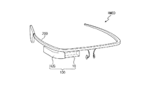
図1は、本発明の一実施形態によるヘッドマウントの電子装置HMEDの斜視図である。図2は、本発明の一実施形態による電子光学装置100のブロック図である。以下、図1及び図2を参照してヘッドマウントの電子装置HMEDに対して説明する。
FIG. 1 is a perspective view of a head-mounted electronic device HMED according to an embodiment of the present invention. FIG. 2 is a block diagram of the electro-
図1に示すように、本実施形態によるヘッドマウントの電子装置HMEDは、電子光学装置100及び使用者の頭(頭部)に着用されるフレーム200を含む。電子光学装置100は、フレーム200に結合される。電子光学装置100のハウジングHUSがフレーム200に結合される。電子光学装置100は、フレーム200に脱着/付着させることができる。
As shown in FIG. 1, the head mounted electronic device HMED according to the present embodiment includes an electron
フレーム200は、眼鏡のフレーム又はサングラスのフレームの機能を有する。フレーム200は、使用者の耳と鼻とによって支持される。本発明の一実施形態でヘッドマウントの電子装置HMEDは、フレームに結合された眼鏡用又はサングラス用のレンズをさらに含むようにしてもよい。
The
電子光学装置100は、フレーム200に対する動作位置(operating position)が可変できるようにフレーム200に結合される。即ち、電子光学装置100は、フレーム200に固定されることなく、付着された状態で多様な方向を指示するように操作される。電子光学装置100をフレーム200に結合させる構造は、多様であり、特定な構造に制限されない。例えば、結合構造物は、ヒンジ構造を含むか、或いは複数の関節を具備するアーム構造(arm structure)を含む。
The electro-
図2に示したように、電子光学装置100は、光学モジュール10、ディスプレイモジュール20、カメラモジュール30、通信モジュール40、制御モジュール50、及び電源モジュール60を含む。電子光学装置100の構成は、これに制限されない。電子光学装置100は、外部充電器、有/無線のデータポート、カードソケット(例えば、メモリカード(Memory card)、SIM/UIM card)等に接続される外部インターフェイス及びイメージデータ、音響データ等を格納するメモリ等をさらに含んでもよい。
As shown in FIG. 2, the electro-
図1にはディスプレイモジュール20、カメラモジュール30、通信モジュール40、制御モジュール50、及び電源モジュール60がハウジングHUSに収容された電子光学装置100を例示的に図示した。光学モジュール10は、ハウジングHUSから外部に露出される。
FIG. 1 exemplarily shows an electro-
光学モジュール10は、光透過率が調節される第1切替え可能なミラー層及び第2切替え可能なミラー層を含む。第1切替え可能なミラー層及び第2切替え可能なミラー層の各々は、透過モード、半透過モード、反射モードの中の選択されたモードにしたがって動作する。
The
第1切替え可能なミラー層及び第2切替え可能なミラー層の各々は、透過モードで入射された光の大部分を透過させ、半透過モードで入射された光の一部を透過させ、一部を反射させ、反射モードで入射された光を大部分反射させる。ここで、「半透過モードで入射された光の一部を透過させる」というのは、「透過した光の輝度が入射された光の輝度より減少したこと」を意味する。 Each of the first switchable mirror layer and the second switchable mirror layer transmits most of the light incident in the transmission mode, transmits a part of the light incident in the semi-transmission mode, and partially transmits the light. Is reflected, and most of the light incident in the reflection mode is reflected. Here, “transmitting a part of the incident light in the semi-transmissive mode” means “the luminance of the transmitted light has decreased from the luminance of the incident light”.
例えば、入射した光の80%以上を反射させるとき、第1切替え可能なミラー層及び第2切替え可能なミラー層の各々は、反射モードで動作することと定義することができる。入射した光の40乃至60%以上を反射層又は透過させるとき、第1切替え可能なミラー層及び第2切替え可能なミラー層の各々は、半透過モードで動作することと定義することができる。入射した光の80%以上を透過させるとき、第1切替え可能なミラー層及び第2切替え可能なミラー層の各々は、透過モードで動作することと定義することができる。第1及び第2切替え可能なミラー層の具体的な説明は、後述する。 For example, when reflecting 80% or more of incident light, each of the first switchable mirror layer and the second switchable mirror layer can be defined as operating in a reflective mode. Each of the first switchable mirror layer and the second switchable mirror layer can be defined as operating in a transflective mode when 40 to 60% or more of incident light is reflected or transmitted. When transmitting 80% or more of incident light, each of the first switchable mirror layer and the second switchable mirror layer can be defined as operating in a transmission mode. A specific description of the first and second switchable mirror layers will be given later.
第1及び第2切替え可能なミラー層の動作によってディスプレイモジュール20から生成されたデータイメージは、使用者の目に提供される。尚、カメラモジュール30は、第1及び第2切替え可能なミラー層の動作によって目の情報を有する外部イメージを取得する。尚、使用者は、第1及び第2切替え可能なミラー層の動作によって前面に現れる外部のイメージに重複表示されたデータイメージを取得する。それによって、電子光学装置100は、使用者に拡張現実を提供する。
The data image generated from the
ディスプレイモジュール20は、ディスプレイパネル及びディスプレイパネルを制御する制御回路等を含む。ディスプレイパネルは、液晶表示パネル又は有機発光表示パネル等であり、その種類は、制限されない。尚、ディスプレイモジュール20は、ディスプレイパネルから受信されたデータイメージの焦点を制御するフレネルレンズ(Fresnel lens)を含む。
The
カメラモジュール30は、レンズ、フィルタ、イメージセンサー等を含む。尚、カメラモジュール30は、イメージセンサーの動作を制御する制御回路を含む。
The
通信モジュール40は、ブルートゥース回線又はWi−Fi(Wireless Fidelity)回線等を利用して無線信号を送/受信する。通信モジュール40は、送信する信号を変調して送信する送信回路と、受信される信号を復調する受信回路とを含む。通信モジュール40は、外部のその他の電子装置と無線信号を送/受信する外部通信モジュール及び電子光学装置100の内部構成の間に無線信号を送/受信する内部通信モジュールを含む。例えば、外部通信モジュールは、携帯電話機又はスマート時計又はパーソナルコンピュータと無線信号を送/受信するブルートゥースモジュール及び無線共有器からインターネット信号を送/受信するWi−Fiモジュールを含む。内部通信モジュールは、カメラモジュール30に備えられた第1近距離の通信回路及び制御モジュール50に接続された第2近距離の通信回路を含む。カメラモジュール30は、撮影した外部イメージを第1近距離の通信回路を通じて制御モジュール50に接続された第2近距離の通信回路に提供する。第1及び第2近距離の通信回路は、ブルートゥース通信回路又はジグビー通信回路等を含む。その他にディスプレイモジュール20もやはり近距離の通信回路をさらに含むことができる。
The
制御モジュール50は、電子光学装置100の全般的な動作を制御する。例えば、制御モジュール50は、光学モジュール10、ディスプレイモジュール20、カメラモジュール30、及び通信モジュール40を活性化(active)させるか非活性化(inactive)させる。制御モジュール50は、少なくとも1つのマイクロプロセッサを含む。
The
尚、制御モジュール50は、カメラモジュール30から取得した外部イメージから使用者の目の情報を取出する。使用者の目の情報からデータイメージに対する使用者の反応情報を取得する。複数の情報を提供するデータイメージに対する水晶体の位置を取得して複数の情報に対する使用者の主関心情報を判別することができ、瞳孔の大きさを取得してデータイメージに対する使用者の感情を判別することができる。
Note that the
電源モジュール60は、電子光学装置100の全般的な動作に必要である電源を供給する。電源モジュール60は、使い捨てバッテリー又はリチウム−イオン又はニッケルカドミウムバッテリーのような充電可能なバッテリーを含む。
The
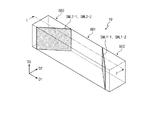
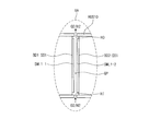
図3Aは、本発明の一実施形態による光学モジュールの斜視図である。図3Bは、図3Aに図示された光学モジュールの平面図である。図3Cは、図3AのI−I’に沿って切断した光学モジュールの断面図である。図3Dは、図3Cの一部分を拡大した図面である。図3E及び図3Fは、本発明の一実施形態による光学モジュールの平面図である。以下、図3A乃至図3Fを参照して光学モジュール10に対してより詳細に説明する。以下、直交する第1方向D1と第2方向D2とは、光学モジュール10の上面と背面を定義し、第3方向D3は、光学モジュール10の厚さ方向を指示する。言い換えれば、第3方向D3は、第1方向D1と第2方向D2とが定義する平面の法線方向である。
FIG. 3A is a perspective view of an optical module according to an embodiment of the present invention. FIG. 3B is a plan view of the optical module illustrated in FIG. 3A. FIG. 3C is a cross-sectional view of the optical module taken along the line I-I ′ of FIG. 3A. FIG. 3D is an enlarged view of a part of FIG. 3C. 3E and 3F are plan views of an optical module according to an embodiment of the present invention. Hereinafter, the
図3A乃至図3Dに示したように、光学モジュール10は、第1ボディー部BD1、第2ボディー部BD2、及び第3ボディー部BD3を含む。第1ボディー部BD1、第2ボディー部BD2、及び第3ボディー部BD3の各々は、透明な材質で、例えば、ガラス又はプラスチック等を含む。第1ボディー部BD1、第2ボディー部BD2、及び第3ボディー部BD3は、互いに結合及び分離される。
As shown in FIGS. 3A to 3D, the
第1ボディー部BD1、第2ボディー部BD2、及び第3ボディー部BD3の各々は、上面BD1−US、BD2−US、BD3−US、背面BD1−LS、BD2−LS、BD3−LS、及び複数の側面BD1−SS1〜BD1−SS4、BD2−SS1〜BD2−SS4、BD3−SS1〜BD3−SS4を含む。第1ボディー部BD1、第2ボディー部BD2、及び第3ボディー部BD3の各々の複数の側面BD1−SS1〜BD1−SS4、BD2−SS1〜BD2−SS4、BD3−SS1〜BD3−SS4は、上面BD1−US、BD2−US、BD3−US及び背面BD1−LS、BD2−LS、BD3−LSの中で少なくともいずれか1つに直交する。 Each of the first body part BD1, the second body part BD2, and the third body part BD3 includes an upper surface BD1-US, BD2-US, BD3-US, a rear surface BD1-LS, BD2-LS, BD3-LS, and a plurality of them. Side surfaces BD1-SS1 to BD1-SS4, BD2-SS1 to BD2-SS4, and BD3-SS1 to BD3-SS4. The plurality of side surfaces BD1-SS1 to BD1-SS4, BD2-SS1 to BD2-SS4, and BD3-SS1 to BD3-SS4 of each of the first body part BD1, the second body part BD2, and the third body part BD3 are upper surfaces. It is orthogonal to at least one of BD1-US, BD2-US, BD3-US, and back BD1-LS, BD2-LS, BD3-LS.
本実施形態で4つの側面BD1−SS1〜BD1−SS4、BD2−SS1〜BD2−SS4、BD3−SS1〜BD3−SS4を各々具備する正方柱形状の第1ボディー部BD1、第2ボディー部BD2、及び第3ボディー部BD3を例示的に図示しているが、第1ボディー部BD1、第2ボディー部BD2、及び第3ボディー部BD3の形状は、これに制限されない。本実施形態で第1ボディー部BD1、第2ボディー部BD2、及び第3ボディー部BD3が結合された光学モジュール10は、第1方向D1の長さが第2方向D2の長さより長い長方形柱形状を有しているが、光学モジュール10の形状は、これに制限されない。
In the present embodiment, the first body portion BD1 and the second body portion BD2 having a square pillar shape each having four side surfaces BD1-SS1 to BD1-SS4, BD2-SS1 to BD2-SS4, and BD3-SS1 to BD3-SS4, The third body part BD3 is exemplarily illustrated, but the shapes of the first body part BD1, the second body part BD2, and the third body part BD3 are not limited thereto. The
特段図示していないが、通信モジュール40及び制御モジュール50は、回路基板に実装された形態で、第1ボディー部BD1、第2ボディー部BD2、及び第3ボディー部BD3の上面BD1−US、BD2−US、BD3−US又は背面BD1−LS、BD2−LS、BD3−LS上に配置される。電源モジュール60も、第1ボディー部BD1、第2ボディー部BD2、及び第3ボディー部BD3の上面BD1−US、BD2−US、BD3−US又は背面BD1−LS、BD2−LS、BD3−LS上に配置される。このとき、ハウジングHUS(図1参照)は、回路基板をカバーする形態に変形される。通信モジュール40、制御モジュール50、及び電源モジュール60の位置は、制限されるわけではなく、電子光学装置のデザインにしたがって多様に変更され得る。
Although not particularly shown, the
図3B及び図3Cに示したように、第1ボディー部BD1は、第1対角面BD1−SS1及び第2対角面BD1−SS2、第1連結面BD1−SS3、及び第2連結面BD1−SS4を含む。第1対角面BD1−SS1及び第2対角面BD1−SS2は、第1方向D1で対向し、第1連結面BD1−SS3、及び第2連結面BD1−SS4は、第2方向D2で対向する。 As shown in FIGS. 3B and 3C, the first body part BD1 includes the first diagonal surface BD1-SS1, the second diagonal surface BD1-SS2, the first connection surface BD1-SS3, and the second connection surface BD1. -Includes SS4. The first diagonal surface BD1-SS1 and the second diagonal surface BD1-SS2 face each other in the first direction D1, and the first connection surface BD1-SS3 and the second connection surface BD1-SS4 are in the second direction D2. opposite.
第2ボディー部BD2は、対角面BD2−SS1(以下、第3対角面)、第1連結面BD2−SS2、第2連結面BD2−SS3、及び第3連結面BD2−SS4を含む。第3対角面BD2−SS1は、第1対角面BD1−SS1に平行に対向する。第3対角面BD2−SS1及び第1連結面BD2−SS2は、第1方向D1で対向し、第2連結面BD2−SS3、及び第3連結面BD2−SS4は、第2方向D2で対向する。 The second body part BD2 includes a diagonal surface BD2-SS1 (hereinafter referred to as a third diagonal surface), a first connection surface BD2-SS2, a second connection surface BD2-SS3, and a third connection surface BD2-SS4. The third diagonal surface BD2-SS1 faces the first diagonal surface BD1-SS1 in parallel. The third diagonal surface BD2-SS1 and the first connection surface BD2-SS2 face each other in the first direction D1, and the second connection surface BD2-SS3 and the third connection surface BD2-SS4 face each other in the second direction D2. To do.
第3ボディー部BD3は、対角面BD3−SS1(以下、第4対角面)、第1連結面BD3−SS2、第2連結面BD3−SS3、及び第3連結面BD3−SS4を含む。第4対角面BD3−SS1は、第2対角面BD1−SS2に平行に対向する。第4対角面BD3−SS1及び第1連結面BD3−SS2は、第1方向D1で対向し、第2連結面BD3−SS3、及び第3連結面BD3−SS4は、第2方向D2で対向する。 The third body part BD3 includes a diagonal surface BD3-SS1 (hereinafter, a fourth diagonal surface), a first connection surface BD3-SS2, a second connection surface BD3-SS3, and a third connection surface BD3-SS4. The fourth diagonal surface BD3-SS1 faces the second diagonal surface BD1-SS2 in parallel. The fourth diagonal surface BD3-SS1 and the first connection surface BD3-SS2 face each other in the first direction D1, and the second connection surface BD3-SS3 and the third connection surface BD3-SS4 face each other in the second direction D2. To do.
第1対角面BD1−SS1と第3対角面BD2−SS1とは、所定のギャップGPを形成する。第1切替え可能なミラー層SML1−1、SML1−2は、第1対角面BD1−SS1と第3対角面BD2−SS1との間に配置される。第1切替え可能なミラー層SML1−1、SML1−2は、第1対角面BD1−SS1と第3対角面BD2−SS1とに各々配置される。本発明の一実施形態で第1対角面BD1−SS1と第3対角面BD2−SS1とに各々配置された2つの第1切替え可能なミラー層SML1−1、SML1−2の中でいずれか1つは、省略されてもよい。 The first diagonal surface BD1-SS1 and the third diagonal surface BD2-SS1 form a predetermined gap GP. The first switchable mirror layers SML1-1 and SML1-2 are disposed between the first diagonal plane BD1-SS1 and the third diagonal plane BD2-SS1. The first switchable mirror layers SML1-1 and SML1-2 are arranged on the first diagonal plane BD1-SS1 and the third diagonal plane BD2-SS1, respectively. In one embodiment of the present invention, any one of the two first switchable mirror layers SML1-1 and SML1-2 respectively disposed on the first diagonal plane BD1-SS1 and the third diagonal plane BD2-SS1. One of them may be omitted.
第2対角面BD1−SS2と第4対角面BD3−SS1もやはり所定のギャップGPを形成する。第2切替え可能なミラー層SML2−1、SML2−2は、第2対角面BD1−SS2と第4対角面BD3−SS1との間に配置される。第2切替え可能なミラー層SML2−1、SML2−2は、第2対角面BD1−SS2と第4対角面BD3−SS1とに各々配置される。本発明の一実施形態で第2対角面BD1−SS2と第4対角面BD3−SS1とに各々配置された2つの第2切替え可能なミラー層SML2−1、SML2−2の中でいずれか1つは、省略されてもよい。 The second diagonal surface BD1-SS2 and the fourth diagonal surface BD3-SS1 also form a predetermined gap GP. The second switchable mirror layers SML2-1 and SML2-2 are disposed between the second diagonal plane BD1-SS2 and the fourth diagonal plane BD3-SS1. The second switchable mirror layers SML2-1 and SML2-2 are arranged on the second diagonal plane BD1-SS2 and the fourth diagonal plane BD3-SS1, respectively. In one embodiment of the present invention, any of the two second switchable mirror layers SML2-1 and SML2-2 respectively disposed on the second diagonal plane BD1-SS2 and the fourth diagonal plane BD3-SS1. One of them may be omitted.
第1切替え可能なミラー層SML1−1、SML1−2と第2切替え可能なミラー層SML2−1、SML2−2とは、印加された電流/電圧によって透過率が変化するエレクトロクロミック材料(electrochromic material)、温度にしたがって透過率が変化するサーモクロミック材料(thermochromic material)、又は周囲のガスによって透過率が変化するガスクロミック材料(gasochromic material)の中で、いずれか1つを含むようにしてもよい。第1切替え可能なミラー層SML1−1、SML1−2と第2切替え可能なミラー層SML2−1、SML2−2とは、材料の中でいずれか1つを含めば十分であり、特定な材料に限定されない。 The first switchable mirror layers SML1-1 and SML1-2 and the second switchable mirror layers SML2-1 and SML2-2 are made of an electrochromic material whose transmittance changes according to an applied current / voltage. ), A thermochromic material whose transmittance changes according to temperature, or a gaschromic material whose transmittance changes depending on the surrounding gas. It is sufficient that the first switchable mirror layers SML1-1 and SML1-2 and the second switchable mirror layers SML2-1 and SML2-2 include any one of the materials. It is not limited to.
ディスプレイモジュール20は、第1切替え可能なミラー層SML1−1、SML1−2に向かってデータイメージを表示するように第1ボディー部BD1の第2連結面BD1−SS4に対向するように配置される。ディスプレイモジュール20は、第2連結面BD1−SS4の一部分に対向し、一部分は、第1対角面BD1−SS1が第2方向D2に投影された部分である。カメラモジュール30は、第2ボディー部BD2の第1連結面BD2−SS2に対向するように配置される。
The
図3Dに示したように、第1切替え可能なミラー層SML1と第2切替え可能なミラー層SML2とは、ガスクロミック材料(gasochromic material)の1つであるマグネシウム−ニッケル合金を含む。マグネシウム−ニッケル合金は、水素化されることによって、透過率が増加し、脱水素化されることによって、透過率が減少する。水素化又は脱水素化の程度にしたがって第1切替え可能なミラー層SML1と第2切替え可能なミラー層SML2との透過率を制御する。 As shown in FIG. 3D, the first switchable mirror layer SML1 and the second switchable mirror layer SML2 include a magnesium-nickel alloy, which is one of gaschromic materials. Magnesium-nickel alloys increase in permeability by being hydrogenated and decrease in permeability by being dehydrogenated. The transmittance of the first switchable mirror layer SML1 and the second switchable mirror layer SML2 is controlled according to the degree of hydrogenation or dehydrogenation.
光学モジュール10は、流入口HIと流出口HOとを除外してギャップGPを密封する密封ハウジングHUS10を含む。密封ハウジングHUS10は、第1ボディー部BD1と類似に透明な材料から製造される。流入口HIに酸素(O2)又は水素H2が供給され、流出口HOを通じて酸素(O2)又は水素H2が排出される。ギャップGPに水素H2が供給されれば、第1切替え可能なミラー層SML1−1、SML1−2の透過率は、増加され、ギャップGPに酸素(O2)が供給されれば、第1切替え可能なミラー層SML1−1、SML1−2の透過率は、減少される。別に図示しなかったが、光学モジュール10は、ギャップGPに酸素(O2)又は水素H2を供給するガス供給部材をさらに含んでもよい。
The
別に示してなかったが、エレクトロクロミック材料を含む切替え可能なミラー層を具備する光学部材は、切替え可能なミラー層に電流/電圧を提供する配線をさらに含む。配線は、ボディー部に配置される。尚、サーモクロミック材料を含む切替え可能なミラー層を具備する光学部材は、切替え可能なミラー層に熱を提供する熱源をさらに含む。 Although not shown separately, an optical member comprising a switchable mirror layer comprising an electrochromic material further includes wiring that provides current / voltage to the switchable mirror layer. The wiring is arranged in the body part. Note that the optical member having the switchable mirror layer including the thermochromic material further includes a heat source for providing heat to the switchable mirror layer.
図3E及び図3Fに示したように、光学モジュール10−1、10−2の形状は、多様に変形することができる。 As shown in FIGS. 3E and 3F, the shapes of the optical modules 10-1 and 10-2 can be variously modified.
図3Eに示したように、第1方向D1と第2方向D2とが定義する平面上で、光学モジュール10−1は、第1方向D1に延長された部分と第2方向D2に延長された部分とを含む。 As shown in FIG. 3E, the optical module 10-1 is extended in the first direction D1 and the second direction D2 on the plane defined by the first direction D1 and the second direction D2. Part.
第1ボディー部BD1−1の側面は、第1対角面BD1−SS1及び第2対角面BD1−SS2、第1乃至第5連結面BD1−SS3〜BD1−SS7を含む。第1対角面BD1−SS1と第2対角面BD1−SS2とは、第1方向D1で対向し、第1連結面BD1−SS3と第2連結面BD1−SS4は、第2方向D2で対向する。第3連結面BD1−SS5と第4連結面BD1−SS6とは、第1方向D1で対向し、第1対角面BD1−SS1と第5連結面BD1−SS7とは、第2方向D2で対向する。 The side surface of the first body part BD1-1 includes a first diagonal surface BD1-SS1, a second diagonal surface BD1-SS2, and first to fifth connection surfaces BD1-SS3 to BD1-SS7. The first diagonal surface BD1-SS1 and the second diagonal surface BD1-SS2 face each other in the first direction D1, and the first connection surface BD1-SS3 and the second connection surface BD1-SS4 are in the second direction D2. opposite. The third connecting surface BD1-SS5 and the fourth connecting surface BD1-SS6 face each other in the first direction D1, and the first diagonal surface BD1-SS1 and the fifth connecting surface BD1-SS7 are in the second direction D2. opposite.
第2ボディー部BD2−1は、第3対角面BD2−SS1、第1連結面BD2−SS2、及び第2連結面BD2−SS3を含む。第3対角面BD2−SS1は、第1対角面BD1−SS1に平行に対向する。第1連結面BD2−SS2と第2連結面BD2−SS3とは、互いに連結され、第3対角面BD2−SS1に各々連結される。 The second body part BD2-1 includes a third diagonal surface BD2-SS1, a first connection surface BD2-SS2, and a second connection surface BD2-SS3. The third diagonal surface BD2-SS1 faces the first diagonal surface BD1-SS1 in parallel. The first connection surface BD2-SS2 and the second connection surface BD2-SS3 are connected to each other and connected to the third diagonal surface BD2-SS1.
第3ボディー部BD3−1は、第4対角面BD3−SS1、第1連結面BD3−SS2、及び第2連結面BD3−SS3を含む。第4対角面BD3−SS1は、第2対角面BD1−SS2に平行に対向する。第1連結面BD3−SS2と第2連結面BD3−SS3とは、互いに連結され、第4対角面BD3−SS1に各々連結される。第3ボディー部BD3−1の第1連結面BD3−SS2は、第2ボディー部BD2−1の第1連結面BD2−SS2に第1方向D1で互いに平行に対向する。 The third body part BD3-1 includes a fourth diagonal surface BD3-SS1, a first connection surface BD3-SS2, and a second connection surface BD3-SS3. The fourth diagonal surface BD3-SS1 faces the second diagonal surface BD1-SS2 in parallel. The first connection surface BD3-SS2 and the second connection surface BD3-SS3 are connected to each other and connected to the fourth diagonal surface BD3-SS1. The first connection surfaces BD3-SS2 of the third body part BD3-1 are opposed to the first connection surfaces BD2-SS2 of the second body part BD2-1 in parallel with each other in the first direction D1.
ディスプレイモジュール20は、第1切替え可能なミラー層SML1−1、SML1−2に向かってデータイメージを表示するように第1ボディー部BD1−1の第5連結面BD1−SS7に対向するように配置される。第5連結面BD1−SS7は、第1対角面BD1−SS1が第2方向D2に投影された部分と重畳する。カメラモジュール30は、第2ボディー部BD2−1の第1連結面BD2−SS2に対向するように配置される。
The
図3Fに示したように、第1方向D1と第2方向D2とが定義する平面上で、光学モジュール10−2は、第1方向D1に延長された部分と第2方向D2に延長された部分を含む。第1ボディー部BD1−2は、ディスプレイモジュール20が配置される第1溝部H1を含み、第2ボディー部BD2−2は、カメラモジュール30が配置される第2溝部H2を含む。
As shown in FIG. 3F, the optical module 10-2 is extended in the first direction D1 and the second direction D2 on the plane defined by the first direction D1 and the second direction D2. Including parts. The first body part BD1-2 includes a first groove part H1 in which the
第1溝部H1は、第1ボディー部BD1−2の第5連結面BD1−SS70に形成される。第5連結面BD1−SS70は、第1溝部H1を形成する複数の部分連結面を含む。第2溝部H2は、第2ボディー部BD2−2の第1連結面BD2−SS20に形成される。第1連結面BD2−SS20は、第2溝部H2を形成する複数の部分連結面を含む。 The first groove part H1 is formed in the fifth connection surface BD1-SS70 of the first body part BD1-2. The fifth connection surface BD1-SS70 includes a plurality of partial connection surfaces that form the first groove H1. The second groove part H2 is formed on the first connection surface BD2-SS20 of the second body part BD2-2. The first connection surface BD2-SS20 includes a plurality of partial connection surfaces that form the second groove H2.
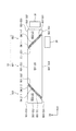
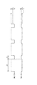
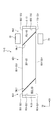
図4Aは、本発明の一実施形態による電子光学装置の第1動作を示した図面である。図4Bは、本発明の一実施形態による電子光学装置の第2動作を示した図面である。図4Cは、本発明の一実施形態による電子光学装置の第1及び第2動作のための切替え可能なミラー層の動作を示したタイミングチャートである。 FIG. 4A is a diagram illustrating a first operation of the electro-optical device according to an embodiment of the present invention. FIG. 4B is a diagram illustrating a second operation of the electron optical device according to the embodiment of the present invention. FIG. 4C is a timing chart illustrating the operation of the switchable mirror layer for the first and second operations of the electro-optical device according to an embodiment of the present invention.
以下、図1乃至図3Fを参照して説明した構成と同一の構成に対する詳細な説明は、省略する。図3B及び図3Cに図示された2つの第1切替え可能なミラー層SML1−1、SML1−2は、1つの第1切替え可能なミラー層SML1に置き換えられ、2つの第2切替え可能なミラー層SML2−1、SML2−2は、1つの第2切替え可能なミラー層SML2に置き換えられる。尚、第1乃至第4対角面BD1−SS1、BD1−SS2、BD2−SS1、BD3−SS1は、図示されていない。 Hereinafter, detailed description of the same configuration as that described with reference to FIGS. 1 to 3F is omitted. The two first switchable mirror layers SML1-1 and SML1-2 illustrated in FIGS. 3B and 3C are replaced with one first switchable mirror layer SML1, and two second switchable mirror layers are provided. SML2-1 and SML2-2 are replaced by one second switchable mirror layer SML2. The first to fourth diagonal surfaces BD1-SS1, BD1-SS2, BD2-SS1, and BD3-SS1 are not shown.
図4A及び図4Bに示したように、第1切替え可能なミラー層SML1及び第2切替え可能なミラー層SML2は、第1方向D1に離隔される。第1切替え可能なミラー層SML1に平行な第1仮想面IS1と第2切替え可能なミラー層SML2に平行な第2仮想面IS2とは、互いに交差する。第1仮想面IS1と第2仮想面IS2とが成す挟角θは、90°より大きいことが望ましい。これは、後述する第1区間の間にディスプレイモジュール20から生成されたデータイメージが使用者の目UIに適切に提供されるようにするためである。
As shown in FIGS. 4A and 4B, the first switchable mirror layer SML1 and the second switchable mirror layer SML2 are spaced apart in the first direction D1. The first virtual surface IS1 parallel to the first switchable mirror layer SML1 and the second virtual surface IS2 parallel to the second switchable mirror layer SML2 intersect each other. It is desirable that the included angle θ formed by the first virtual surface IS1 and the second virtual surface IS2 is greater than 90 °. This is for the purpose of appropriately providing the data image generated from the
第1切替え可能なミラー層SML1及び第2切替え可能なミラー層SML2は、所定の区間の間に使用者によって設定された動作モード、即ち、透過モード、半透過モード、及び反射モードの中のいずれか1つの動作モードで動作する。 The first switchable mirror layer SML1 and the second switchable mirror layer SML2 may be in any one of operation modes set by the user during a predetermined period, that is, a transmission mode, a semi-transmission mode, and a reflection mode. It operates in one mode of operation.
図4A及び図4Cに示したように、第1区間P1の間に第1切替え可能なミラー層SML1は、反射モードBLで動作し、第1区間P1の間に第2切替え可能なミラー層SML2は、半透過モードHTLで動作する。第1区間P1の間にディスプレイモジュール20から生成されたデータイメージは、第1経路L−1を通じて使用者の目UIに提供される。ディスプレイモジュール20から生成されたデータイメージは、第1切替え可能なミラー層SML1に提供され、第1切替え可能なミラー層SML1から反射されたデータイメージは、第2切替え可能なミラー層SML2に提供され、第2切替え可能なミラー層SML2は、一部のデータイメージを透過させて一部のデータイメージを使用者の目UIに反射させる。
4A and 4C, the first switchable mirror layer SML1 during the first section P1 operates in the reflection mode BL, and the second switchable mirror layer SML2 during the first section P1. Operates in transflective mode HTL. The data image generated from the
第1区間P1の間に、使用者は、第2経路L−2を通じて使用者の前面の外部イメージを認知する。データイメージは、使用者の前面の外部のイメージに関連された情報を提供する。したがって、電気光学装置10は、使用者に拡張現実を提供する。第1区間P1の間にカメラモジュール30は、第3経路L−3を通じて使用者前面の外部イメージを取得する。
During the first section P1, the user recognizes an external image of the front surface of the user through the second route L-2. The data image provides information related to the external image in front of the user. Therefore, the electro-
図4B及び図4Cに示したように、第2区間P2の間に第1切替え可能なミラー層SML1は、透過モードTLで動作し、第2区間P2の間に第2切替え可能なミラー層SML2は、半透過モードHTLで動作する。第2区間P2の間に使用者の目の情報を有する外部イメージ(以下、目の情報イメージ)は、第4経路L−4を通じてカメラモジュール30に提供される。目の情報イメージは、第2切替え可能なミラー層SML2に提供され、第2切替え可能なミラー層SML2から反射された目の情報イメージは、第1切替え可能なミラー層SML1に提供され、第1切替え可能なミラー層SML1を透過した目の情報イメージは、カメラモジュール30に提供される。
As shown in FIGS. 4B and 4C, the first switchable mirror layer SML1 during the second section P2 operates in the transmission mode TL, and the second switchable mirror layer SML2 during the second section P2. Operates in transflective mode HTL. An external image having the user's eye information (hereinafter referred to as an eye information image) during the second section P2 is provided to the
第1切替え可能なミラー層SML1で目の情報イメージの輝度が減少されることを最小化するために第2区間P2の間に第1切替え可能なミラー層SML1の透過率は、90%以上に設定される。第2区間P2の間に、使用者は、相変わらず、第2経路L−2を通じて使用者前面の外部イメージを認知する。 In order to minimize the reduction of the brightness of the information image of the eye in the first switchable mirror layer SML1, the transmittance of the first switchable mirror layer SML1 during the second section P2 is 90% or more. Is set. During the second section P2, the user still recognizes the external image of the front of the user through the second route L-2.
第1区間P1及び第2区間P2の間に第2切替え可能なミラー層SML2が半透過モードHTLで動作しても、第1区間P1及び第2区間P2の透過率は、互いに異なりに調節される。第2区間P2の間の第2切替え可能なミラー層SML2の透過率は、第1区間P1の間の第2切替え可能なミラー層SML2の透過率より低い。第2区間P2の間の第2切替え可能なミラー層SML2の反射率を高めてカメラモジュール30に鮮明な目の情報イメージを提供するためである。
Even if the second switchable mirror layer SML2 operates in the semi-transmissive mode HTL between the first section P1 and the second section P2, the transmittances of the first section P1 and the second section P2 are adjusted differently. The The transmittance of the second switchable mirror layer SML2 during the second section P2 is lower than the transmittance of the second switchable mirror layer SML2 during the first section P1. This is because the reflectance of the second switchable mirror layer SML2 during the second section P2 is increased to provide the
図4Cに示したように第1区間P1と第2区間P2とは、交互に定義される。この時、各々の第2区間P2は、各々の第1区間P1に比べて非常に短い時間を有する。第2区間P2は、互いに同一の時間を有し、例えば、数マイクロ秒乃至数十マイクロ秒である。第1区間P1は、互いに同一の時間を有し、例えば、数秒乃至数十秒である。 As shown in FIG. 4C, the first section P1 and the second section P2 are defined alternately. At this time, each second section P2 has a much shorter time than each first section P1. The second section P2 has the same time, for example, several microseconds to several tens of microseconds. The first section P1 has the same time, for example, several seconds to several tens of seconds.
本発明の一実施形態で第2区間P2の間に第2切替え可能なミラー層SML2は、反射モードBLで動作する。第2区間P2の間の第2切替え可能なミラー層SML2の反射率を高めてカメラモジュール30に鮮明な目の情報イメージを提供するためである。第2区間P2が短い時間に設定されたので、使用者は、第2区間P2の間の第2切替え可能なミラー層SML2の動作を認知できない。したがって、使用者は、区間に関わらず前面の外部イメージを連続的に認知する。
In an embodiment of the present invention, the second switchable mirror layer SML2 during the second period P2 operates in the reflection mode BL. This is because the reflectance of the second switchable mirror layer SML2 during the second section P2 is increased to provide the
ディスプレイモジュール20とカメラモジュール30とは、第1区間P1と第2区間P2との中で、特定な区間のみを活性化される。ディスプレイモジュール20とカメラモジュール30とは、第1区間P1と第2区間P2とに関わらず、活性化されてもよい。例えば、ディスプレイモジュール20は、第1区間P1の間に活性化され、カメラモジュール30は、第1区間P1及び第2区間P2の間に活性化される。
The
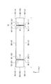
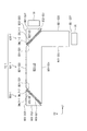
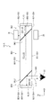
図5は、本発明の一実施形態による電子光学装置の平面図である。図6Aは、図5に図示された電子光学装置の第1動作を示した図面である。図6Bは、図5に図示された電子光学装置の第2動作を示した図面である。図6Cは、図5に図示された電子光学装置の第1及び第2動作のための切替え可能なミラー層の動作を示したタイミングチャートである。以下、図1乃至図4Cを参照して説明した構成と同一の構成に対する詳細な説明は、省略する。 FIG. 5 is a plan view of an electron optical device according to an embodiment of the present invention. 6A is a diagram illustrating a first operation of the electron optical device illustrated in FIG. 5. 6B is a diagram illustrating a second operation of the electro-optical device illustrated in FIG. FIG. 6C is a timing chart showing the operation of the switchable mirror layer for the first and second operations of the electron optical device shown in FIG. Hereinafter, detailed description of the same configuration as that described with reference to FIGS. 1 to 4C is omitted.
図5に示したように、本実施形態による光学モジュール10−3は、第1ボディー部BD1、第2ボディー部BD2、及び第3ボディー部BD3を含む。第1切替え可能なミラー層SML1に平行な第1仮想面IS1と第2切替え可能なミラー層SML2に平行な第2仮想面IS2とは、互いに交差する。 As shown in FIG. 5, the optical module 10-3 according to the present embodiment includes a first body part BD1, a second body part BD2, and a third body part BD3. The first virtual surface IS1 parallel to the first switchable mirror layer SML1 and the second virtual surface IS2 parallel to the second switchable mirror layer SML2 intersect each other.
本実施形態による光学モジュール10−3は、第2ボディー部BD2の第1連結面BD2−SS2に配置された反射層RL10をさらに含む。第2ボディー部BD2の第1連結面BD2−SS2は、第1切替え可能なミラー層SML1と第1方向D1で対向する。カメラモジュール30は、第1切替え可能なミラー層SML1から反射された目の情報イメージを受信するように第2ボディー部BD2の第2連結面BD2−SS3に対向するように配置される。第2ボディー部BD2の第2連結面BD2−SS3は、第1切替え可能なミラー層SML1と第2方向D2で対向する。ディスプレイモジュール20は、第1切替え可能なミラー層SML1に向かってデータイメージを表示するように第1ボディー部BD1の第2連結面BD1−SS4に対向するように配置される。
The optical module 10-3 according to the present embodiment further includes a reflective layer RL10 disposed on the first coupling surface BD2-SS2 of the second body part BD2. The first coupling surface BD2-SS2 of the second body part BD2 faces the first switchable mirror layer SML1 in the first direction D1. The
図6A及び図6Cに示したように、第1区間P1の間に第1切替え可能なミラー層SML1は、反射モードBLで動作し、第1区間P1の間に第2切替え可能なミラー層SML2は、半透過モードHTLで動作する。第1区間P1の間にディスプレイモジュール20から生成されたデータイメージは、第1経路L−1を通じて使用者の目UIに提供される。第1経路L−1は、図4Aを参照して説明した第1経路L−1と実質的に同一であり、詳細な説明は、省略する。第1区間P1の間に、使用者は、第2経路L−2を通して使用者前面の外部イメージを認知する。データイメージは、使用者前面の外部のイメージに関連された情報を提供する。したがって、電気光学装置10は、使用者に拡張現実を提供する。
As shown in FIGS. 6A and 6C, the first switchable mirror layer SML1 during the first section P1 operates in the reflection mode BL, and the second switchable mirror layer SML2 during the first section P1. Operates in transflective mode HTL. The data image generated from the
図6B及び図6Cに示したように、第2区間P2の間に第1切替え可能なミラー層SML1は、半透過モードHTLで動作し、第2区間P2の間に第2切替え可能なミラー層SML2は、半透過モードHTLで動作する。第2区間P2の間に目の情報イメージは、第3経路L−30を通じてカメラモジュール30に提供される。目の情報イメージは、第2切替え可能なミラー層SML2に提供され、第2切替え可能なミラー層SML2は、目の情報イメージの一部を反射させる。第2切替え可能なミラー層SML2から反射された目の情報イメージの一部は、第1切替え可能なミラー層SML1を通過する。第1切替え可能なミラー層SML1を通過した目の情報イメージは、反射層RL10で反射され、反射層RL10で反射された目の情報イメージの一部は、第1切替え可能なミラー層SML1から反射された後、カメラモジュール30に提供される。第2区間P2の間に、使用者は、変わらず、第2経路L−2を通じて使用者前面の外部イメージを認知する。
As shown in FIGS. 6B and 6C, the first switchable mirror layer SML1 during the second section P2 operates in the transflective mode HTL, and the second switchable mirror layer during the second section P2. SML2 operates in translucent mode HTL. The information image of the eye is provided to the
第1区間P1及び第2区間P2の間に第2切替え可能なミラー層SML2が半透過モードHTLで動作しても、第1区間P1及び第2区間P2の透過率は、互いに異なって調節される。尚、第2区間P2の間に第2切替え可能なミラー層SML2と第1切替え可能なミラー層SML1とが半透過モードHTLで動作しても、第2切替え可能なミラー層SML2と第1切替え可能なミラー層SML1との透過率は、互いに異なって調節される。 Even if the second switchable mirror layer SML2 operates in the semi-transmissive mode HTL between the first section P1 and the second section P2, the transmittance of the first section P1 and the second section P2 is adjusted differently. The Even if the second switchable mirror layer SML2 and the first switchable mirror layer SML1 operate in the semi-transmissive mode HTL during the second section P2, the second switchable mirror layer SML2 and the first switchover are provided. The transmittance with the possible mirror layer SML1 is adjusted differently.
第2区間P2の間の第2切替え可能なミラー層SML2の透過率は、第1区間P1の間の第2切替え可能なミラー層SML2の透過率より低い。尚、第2区間P2の間の第2切替え可能なミラー層SML2の透過率は、第1切替え可能なミラー層SML1の透過率より低い。第2区間P2の間の第2切替え可能なミラー層SML2の反射率を高めてカメラモジュール30に鮮明な目の情報イメージを提供するためである。
The transmittance of the second switchable mirror layer SML2 during the second section P2 is lower than the transmittance of the second switchable mirror layer SML2 during the first section P1. Note that the transmittance of the second switchable mirror layer SML2 during the second section P2 is lower than the transmittance of the first switchable mirror layer SML1. This is because the reflectance of the second switchable mirror layer SML2 during the second section P2 is increased to provide the
第2区間P2が第1区間P1に比べて非常に短い時間に設定されたとき、例えば、数マイクロ秒乃至数十マイクロ秒に設定されたとき、第2区間P2の間に第2切替え可能なミラー層SML2は、反射モードBLで動作する。第2区間P2の間の第2切替え可能なミラー層SML2の反射率を高めてカメラモジュール30に鮮明な目の情報イメージを提供するためである。第2区間P2が短い時間に設定されれば、使用者は、第2区間P2の間の第2切替え可能なミラー層SML2の動作を認知できない。
When the second section P2 is set to a very short time compared to the first section P1, for example, when set to several microseconds to several tens of microseconds, the second switching can be performed during the second section P2. The mirror layer SML2 operates in the reflection mode BL. This is because the reflectance of the second switchable mirror layer SML2 during the second section P2 is increased to provide the
本実施形態で、ディスプレイモジュール20は、第1区間P1の間に活性化され、カメラモジュール30は、第2区間P2の間に活性化される。ディスプレイモジュール20は、第2区間P2の間に活性化されるか非活性化される。
In the present embodiment, the
図7は、本発明の一実施形態による電子光学装置の平面図である。図8Aは、図7に図示された電子光学装置の第1動作を示した図面である。図8Bは、図7に図示された電子光学装置の第2動作を示した図面である。図8Cは、図7に図示された電子光学装置の第1及び第2動作のための切替え可能なミラー層の動作を示したタイミングチャートである。以下、図1乃至図6Cを参照して説明した構成と同一の構成に対する詳細な説明は、省略する。 FIG. 7 is a plan view of an electron optical device according to an embodiment of the present invention. FIG. 8A illustrates a first operation of the electro-optical device illustrated in FIG. FIG. 8B is a diagram illustrating a second operation of the electron optical device illustrated in FIG. 7. FIG. 8C is a timing chart showing the operation of the switchable mirror layer for the first and second operations of the electro-optical device shown in FIG. Hereinafter, detailed description of the same configuration as that described with reference to FIGS. 1 to 6C is omitted.
図7に示したように、本実施形態による光学モジュール10−4は、第1ボディー部BD1、第2ボディー部BD2、及び第3ボディー部BD3を含む。第1切替え可能なミラー層SML1と第2切替え可能なミラー層SML2は、実質的に互いに平行になる。別に図示しなかったが、第1乃至第4対角面BD1−SS1、BD1−SS2、BD2−SS1、BD3−SS1は、互いに平行に対向する。 As shown in FIG. 7, the optical module 10-4 according to the present embodiment includes a first body part BD1, a second body part BD2, and a third body part BD3. The first switchable mirror layer SML1 and the second switchable mirror layer SML2 are substantially parallel to each other. Although not shown separately, the first to fourth diagonal surfaces BD1-SS1, BD1-SS2, BD2-SS1, and BD3-SS1 face each other in parallel.
本実施形態による光学モジュール10−4は、第3ボディー部BD3の第1連結面BD3−SS2に配置された反射層RL20をさらに含む。第3ボディー部BD3の第1連結面BD3−SS2は、第2切替え可能なミラー層SML2と第1方向D1で対向する。カメラモジュール30は、第1切替え可能なミラー層SML1を通過した目の情報イメージを受信するように第2ボディー部BD2の第1連結面BD2−SS2に対向するように配置される。第2ボディー部BD2の第1連結面BD2−SS2は、第1切替え可能なミラー層SML1と第1方向D1で対向する。ディスプレイモジュール20は、第1切替え可能なミラー層SML1に向かってデータイメージを表示するように第1ボディー部BD1の第2連結面BD1−SS4に対向するように配置される。
The optical module 10-4 according to the present embodiment further includes a reflective layer RL20 disposed on the first coupling surface BD3-SS2 of the third body part BD3. The first coupling surface BD3-SS2 of the third body part BD3 faces the second switchable mirror layer SML2 in the first direction D1. The
特段図示しないが、光学モジュール10−4は、第3ボディー部BD3の第3連結面BD3−SS4に配置された焦点制御部材をさらに含む。焦点制御部材は、第2切替え可能なミラー層SML2から反射されたデータイメージを反転させるレンズを含む。 Although not particularly illustrated, the optical module 10-4 further includes a focus control member disposed on the third connection surface BD3-SS4 of the third body part BD3. The focus control member includes a lens that inverts the data image reflected from the second switchable mirror layer SML2.
図8A及び図8Cに示したように、第1区間P1の間に第1切替え可能なミラー層SML1は、反射モードBLで動作し、第1区間P1の間に第2切替え可能なミラー層SML2は、半透過モードHTLで動作する。第1区間P1の間にディスプレイモジュール20から生成されたデータイメージは、第1経路L−10を通じて使用者の目UIに提供される。ディスプレイモジュール20から生成されたデータイメージは、第1切替え可能なミラー層SML1に提供され、第1切替え可能なミラー層SML1から反射されたデータイメージは、第2切替え可能なミラー層SML2に提供される。第2切替え可能なミラー層SML2を透過した一部のデータイメージは、反射層RL20で反射された後、第2切替え可能なミラー層SML2に提供される。第2切替え可能なミラー層SML2から反射された一部のデータイメージは、使用者の目UIに提供される。
As shown in FIGS. 8A and 8C, the first switchable mirror layer SML1 during the first section P1 operates in the reflection mode BL, and the second switchable mirror layer SML2 during the first section P1. Operates in transflective mode HTL. The data image generated from the
第1区間P1の間に、使用者は、第2経路L−2を通じて使用者前面の外部イメージを認知する。データイメージは、使用者の前面の外部のイメージに関連された情報を提供する。したがって、電気光学装置10は、使用者に拡張現実を提供する。
During the first section P1, the user recognizes an external image of the front of the user through the second route L-2. The data image provides information related to the external image in front of the user. Therefore, the electro-
図8B及び図8Cに示したように、第2区間P2の間に第1切替え可能なミラー層SML1は、透過モードTLで動作し、第2区間P2の間に第2切替え可能なミラー層SML2は、半透過モードHTLで動作する。第2区間P2の間に目の情報イメージは、第4経路L−40を通じてカメラモジュール30に提供される。目の情報イメージは、第2切替え可能なミラー層SML2に提供され、第2切替え可能なミラー層SML2から反射された一部の目の情報イメージは、反射層RL20に反射された後、第2切替え可能なミラー層SML2に提供される。第2切替え可能なミラー層SML2を通過した一部の目の情報イメージは、第1切替え可能なミラー層SML1を透過した後、カメラモジュール30に提供される。
As shown in FIGS. 8B and 8C, the first switchable mirror layer SML1 during the second section P2 operates in the transmission mode TL, and the second switchable mirror layer SML2 during the second section P2. Operates in transflective mode HTL. The information image of the eye is provided to the
本発明の一実施形態で、第2区間P2が第1区間P1に比べて非常に短い時間に設定されたとき、第2区間P2の間に第2切替え可能なミラー層SML2は、反射モードBLと透過モードTLとで交互に動作する。第2区間P2の各々は、第1サブ区間と第2サブ区間とを含む。第1サブ区間と第2サブ区間とは、交互に定義される。第2切替え可能なミラー層SML2が第1サブ区間の間に反射モードBLで動作して目の情報イメージを反射層RL20に提供し、第1サブ区間に連続する第2サブ区間の間に第2切替え可能なミラー層SML2が透過モードTLで動作して反射層RL20から反射された目の情報イメージを通過させる。第2切替え可能なミラー層SML2を通過した目の情報イメージは、カメラモジュール30に提供される。第2切替え可能なミラー層SML2が第2区間P2の間に時間分割して反射モードBLと透過モードTLとで交互に動作することで、カメラモジュール30に提供される目の情報イメージの輝度を増加させる。
In an embodiment of the present invention, when the second section P2 is set to a very short time compared to the first section P1, the second switchable mirror layer SML2 during the second section P2 has the reflection mode BL. And the transmission mode TL are operated alternately. Each of the second sections P2 includes a first sub section and a second sub section. The first sub-interval and the second sub-interval are defined alternately. The second switchable mirror layer SML2 operates in the reflection mode BL during the first sub-interval to provide an information image of the eye to the reflection layer RL20, and the second sub-interval is continuous between the second sub-intervals. The two-switchable mirror layer SML2 operates in the transmission mode TL to pass the information image of the eye reflected from the reflection layer RL20. The information image of the eye that has passed through the second switchable mirror layer SML2 is provided to the
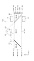
図9は、本発明の一実施形態による電子光学装置の平面図である。図10Aは、図9に図示された電子光学装置の第1動作を示した図面である。図10Bは、図9に図示された電子光学装置の第2動作を示した図面である。図10Cは、図9に図示された電子光学装置の第1及び第2動作のための切替え可能なミラー層の動作を示したタイミングチャートである。以下、図1乃至図8Cを参照して説明した構成と同一の構成に対する詳細な説明は、省略する。 FIG. 9 is a plan view of an electron optical device according to an embodiment of the present invention. FIG. 10A illustrates a first operation of the electro-optical device illustrated in FIG. FIG. 10B is a diagram illustrating a second operation of the electro-optical device illustrated in FIG. 9. FIG. 10C is a timing chart showing the operation of the switchable mirror layer for the first and second operations of the electron optical device shown in FIG. Hereinafter, detailed description of the same configuration as that described with reference to FIGS. 1 to 8C is omitted.
図9に示したように、本実施形態による光学モジュール10−5は、第1ボディー部BD1、第2ボディー部BD2、及び第3ボディー部BD3を含む。第1切替え可能なミラー層SML1と第2切替え可能なミラー層SML2とは、実質的に互いに平行になる。 As shown in FIG. 9, the optical module 10-5 according to the present embodiment includes a first body part BD1, a second body part BD2, and a third body part BD3. The first switchable mirror layer SML1 and the second switchable mirror layer SML2 are substantially parallel to each other.
本実施形態による光学モジュール10−5は、第2ボディー部BD2の第1連結面BD2−SS2に配置された第1反射層RL10及び第3ボディー部BD3の第1連結面BD3−SS2に配置された第2反射層RL20をさらに含む。第2ボディー部BD2の第1連結面BD2−SS2は、第1切替え可能なミラー層SML1と第1方向D1で対向する。カメラモジュール30は、第1切替え可能なミラー層SML1から反射された目の情報イメージを受信するように第2ボディー部BD2の第2連結面BD2−SS3に対向するように配置される。第2ボディー部BD2の第2連結面BD2−SS3は、第1切替え可能なミラー層SML1と第2方向D2で対向する。ディスプレイモジュール20は、第1切替え可能なミラー層SML1に向かってデータイメージを表示するように第1ボディー部BD1の第2連結面BD1−SS4に対向するように配置される。
The optical module 10-5 according to the present embodiment is disposed on the first reflection layer RL10 disposed on the first connection surface BD2-SS2 of the second body part BD2 and the first connection surface BD3-SS2 of the third body part BD3. The second reflective layer RL20 is further included. The first coupling surface BD2-SS2 of the second body part BD2 faces the first switchable mirror layer SML1 in the first direction D1. The
第3ボディー部BD3の第1連結面BD3−SS2は、第2切替え可能なミラー層SML2と第1方向D1で対向する。第3ボディー部BD3の第1連結面BD3−SS2は、第2ボディー部BD2の第1連結面BD2−SS2と第1方向D1で対向する。 The first coupling surface BD3-SS2 of the third body part BD3 faces the second switchable mirror layer SML2 in the first direction D1. The first connection surface BD3-SS2 of the third body part BD3 faces the first connection surface BD2-SS2 of the second body part BD2 in the first direction D1.
図10A及び図10Cに示したように、第1区間P1の間に第1切替え可能なミラー層SML1は、反射モードBLで動作し、第1区間P1の間に第2切替え可能なミラー層SML2は、半透過モードHTLで動作する。第1区間P1の間にディスプレイモジュール20から生成されたデータイメージは、第1経路L−10を通じて使用者の目UIに提供される。第1経路L−10は、図8Aを参照して説明した第1経路L−10と実質的に同一であり、詳細な説明は、省略する。第1区間P1の間に、使用者は、第2経路L−2を通じて使用者前面の外部イメージを認知する。データイメージは、使用者前面の外部のイメージに関連された情報を提供する。したがって、電気光学装置10は、使用者に拡張現実を提供する。
As shown in FIGS. 10A and 10C, the first switchable mirror layer SML1 during the first section P1 operates in the reflection mode BL, and the second switchable mirror layer SML2 during the first section P1. Operates in transflective mode HTL. The data image generated from the
図10B及び図10Cに示したように、第2区間P2の間に第1切替え可能なミラー層SML1は、半透過モードHTLで動作し、第2区間P2の間に第2切替え可能なミラー層SML2は、半透過モードHTLで動作する。目の情報イメージは、第2切替え可能なミラー層SML2に提供され、第2切替え可能なミラー層SML2から反射された一部の目の情報イメージは、第2反射層RL20に反射された後、第2切替え可能なミラー層SML2に提供される。第2切替え可能なミラー層SML2を通過した一部の目の情報イメージは、第1切替え可能なミラー層SML1を通過する。この時、目の情報イメージの輝度は、さらに減少する。第1切替え可能なミラー層SML1を通過した一部の目の情報イメージは、第1反射層RL10で反射し、第1反射層RL10で反射された目の情報イメージの一部は、第1切替え可能なミラー層SML1から反射された後、カメラモジュール30に提供される。
As shown in FIGS. 10B and 10C, the first switchable mirror layer SML1 during the second section P2 operates in the transflective mode HTL, and the second switchable mirror layer during the second section P2. SML2 operates in translucent mode HTL. The information image of the eye is provided to the second switchable mirror layer SML2, and a part of the information image of the eye reflected from the second switchable mirror layer SML2 is reflected on the second reflection layer RL20, A second switchable mirror layer SML2 is provided. The information image of a part of the eyes that has passed through the second switchable mirror layer SML2 passes through the first switchable mirror layer SML1. At this time, the brightness of the information image of the eye further decreases. A part of the eye information image that has passed through the first switchable mirror layer SML1 is reflected by the first reflection layer RL10, and a part of the eye information image reflected by the first reflection layer RL10 is the first switching layer. After being reflected from the possible mirror layer SML1, it is provided to the
以上、本発明の望ましい実施形態を参照して説明したが、当該技術分野の当業者又は当該技術分野に通常の知識を有する者であれば、後述の特許請求の範囲に記載された本発明の思想及び技術領域から逸脱しない範囲内で本発明を多様に修正及び変形できることは理解できる。 The present invention has been described with reference to the preferred embodiments of the present invention. However, those skilled in the art or those who have ordinary knowledge in the technical field may use the present invention described in the claims below. It can be understood that the present invention can be variously modified and changed without departing from the spirit and technical scope.
したがって、本発明の技術的範囲は、明細書の詳細な説明に記載された内容に限定されることではなく、特許請求の範囲によって定められなければならない。 Therefore, the technical scope of the present invention should not be limited to the contents described in the detailed description of the specification, but should be defined by the appended claims.
100 電子光学装置
200 フレーム
10 光学モジュール
20 ディスプレイモジュール
30 カメラモジュール
40 通信モジュール
50 制御モジュール
60 電源モジュール
100 Electro-
Claims (32)
前記フレームに結合された電子光学装置と、を含み、
前記電子光学装置は、
データイメージを生成するディスプレイモジュールと、
光透過率が調節される第1切替え可能なミラー層及び第2切替え可能なミラー層を含み、前記第1切替え可能なミラー層は、前記ディスプレイモジュールから生成されたデータイメージを前記第2切替え可能なミラー層に提供し、前記第2切替え可能なミラー層は、前記第1切替え可能なミラー層から提供されたデータイメージを前記使用者の目に提供する光学モジュールと、
前記第1切替え可能なミラー層及び前記第2切替え可能なミラー層の動作によって前記使用者の目の情報を有する外部イメージを取得するカメラモジュールと、
を含むヘッドマウント電子装置。 A frame worn on the user's head;
An electro-optic device coupled to the frame,
The electro-optical device includes:
A display module for generating a data image;
The first switchable mirror layer includes a first switchable mirror layer and a second switchable mirror layer, the light transmittance of which is adjusted, and the first switchable mirror layer can switch the data image generated from the display module. An optical module for providing to the user's eyes a data image provided from the first switchable mirror layer;
A camera module for acquiring an external image having information of the eyes of the user by operation of the first switchable mirror layer and the second switchable mirror layer;
A head mounted electronic device.
前記第1、第2、及び第3ボディー部の各々は、直交する第1方向と第2方向が定義する上面、前記上面と法線方向に離隔された背面、及び前記上面と前記背面を連結する複数の側面を含み、
前記第1ボディー部の前記複数の側面は、第1対角面及び第2対角面を含み、前記第2ボディー部の前記複数の側面は、前記第1対角面と対向する第3対角面を含み、前記第3ボディー部の前記複数の側面は、前記第2対角面と対向する第4対角面を含み、
前記第1切替え可能なミラー層は、前記第1対角面と前記第3対角面との間に配置され、前記第2切替え可能なミラー層は、前記第2対角面と前記第4対角面との間に配置されたことを特徴とする請求項1に記載のヘッドマウント電子装置。 The optical module includes first, second, and third body parts,
Each of the first, second, and third body parts connects a top surface defined by orthogonal first and second directions, a back surface that is separated from the top surface in a normal direction, and the top surface and the back surface. Including multiple sides to
The plurality of side surfaces of the first body portion include a first diagonal surface and a second diagonal surface, and the plurality of side surfaces of the second body portion are a third pair facing the first diagonal surface. A plurality of side surfaces of the third body portion including a fourth diagonal surface facing the second diagonal surface;
The first switchable mirror layer is disposed between the first diagonal surface and the third diagonal surface, and the second switchable mirror layer includes the second diagonal surface and the fourth diagonal surface. The head-mounted electronic device according to claim 1, wherein the head-mounted electronic device is disposed between the diagonal surfaces.
前記第1切替え可能なミラー層に平行な第1仮想面は、前記第2切替え可能なミラー層に平行な第2仮想面に交差することを特徴とする請求項2に記載のヘッドマウント電子装置。 The first switchable mirror layer and the second switchable mirror layer are spaced apart in the first direction,
3. The head-mounted electronic device according to claim 2, wherein a first virtual plane parallel to the first switchable mirror layer intersects a second virtual plane parallel to the second switchable mirror layer. .
前記ディスプレイモジュールは、前記第1ボディー部の前記複数の側面の中で、前記第2方向で前記第1切替え可能なミラー層に対向するいずれか1つの側面に対向することを特徴とする請求項4に記載のヘッドマウント電子装置。 The camera module is opposed to any one of the plurality of side surfaces of the second body portion facing the first switchable mirror layer in the first direction,
2. The display module according to claim 1, wherein one of the plurality of side surfaces of the first body portion faces one of the side surfaces facing the first switchable mirror layer in the second direction. 5. The head mounted electronic device according to 4.
前記カメラモジュールは、前記第2ボディー部の前記複数の側面の中で、前記第2方向で前記第1切替え可能なミラー層に対向するいずれか1つの側面上に配置され、
前記ディスプレイモジュールは、前記第1ボディー部の前記複数の側面の中で、前記第2方向で前記第1切替え可能なミラー層に対向するいずれか1つの側面に対向することを特徴とする請求項4に記載のヘッドマウント電子装置。 The optical module further includes a reflective layer disposed on any one of the plurality of side surfaces of the second body portion facing the first switchable mirror layer in the first direction. ,
The camera module is disposed on any one of the plurality of side surfaces of the second body portion facing the first switchable mirror layer in the second direction,
2. The display module according to claim 1, wherein one of the plurality of side surfaces of the first body portion faces one of the side surfaces facing the first switchable mirror layer in the second direction. 5. The head mounted electronic device according to 4.
前記第1切替え可能なミラー層と前記第2切替え可能なミラー層とは、互いに平行になることを特徴とする請求項2に記載のヘッドマウント電子装置。 The first switchable mirror layer and the second switchable mirror layer are spaced apart in a first direction;
3. The head mounted electronic device according to claim 2, wherein the first switchable mirror layer and the second switchable mirror layer are parallel to each other.
前記カメラモジュールは、前記第2ボディー部の前記複数の側面の中で、前記第1方向で前記第1切替え可能なミラー層に対向するいずれか1つの側面上に配置され、
前記ディスプレイモジュールは、前記第1ボディー部の前記複数の側面の中で、前記第2方向で前記第1切替え可能なミラー層に対向するいずれか1つの側面に対向することを特徴とする請求項17に記載のヘッドマウント電子装置。 The optical module further includes a reflective layer disposed on any one of the side surfaces of the third body portion facing the second switchable mirror layer in the first direction. ,
The camera module is disposed on any one of the plurality of side surfaces of the second body portion facing the first switchable mirror layer in the first direction,
2. The display module according to claim 1, wherein one of the plurality of side surfaces of the first body portion faces one of the side surfaces facing the first switchable mirror layer in the second direction. 18. A head-mounted electronic device according to item 17.
前記カメラモジュールは、前記第2ボディー部の前記複数の側面の中で、前記第2方向で前記第1切替え可能なミラー層に対向するいずれか1つの側面上に配置され、
前記ディスプレイモジュールは、前記第1ボディー部の前記複数の側面の中で、前記第2方向で前記第1切替え可能なミラー層に対向するいずれか1つの側面に対向することを特徴とする請求項17に記載のヘッドマウント電子装置。 The optical module includes: a first reflective layer disposed on any one of the plurality of side surfaces of the second body portion and facing the first switchable mirror layer in the first direction; A second reflective layer disposed on any one of the plurality of side surfaces of the third body portion facing the second switchable mirror layer in the first direction;
The camera module is disposed on any one of the plurality of side surfaces of the second body portion facing the first switchable mirror layer in the second direction,
2. The display module according to claim 1, wherein one of the plurality of side surfaces of the first body portion faces one of the side surfaces facing the first switchable mirror layer in the second direction. 18. A head-mounted electronic device according to item 17.
前記第2切替え可能なミラー層は、前記第2対角面と前記第3対角面との中で少なくともいずれか1つの面上に配置されたことを特徴とする請求項27に記載のヘッドマウント電子装置。 The first switchable mirror layer is disposed on at least one of the first diagonal surface and the third diagonal surface;
28. The head according to claim 27, wherein the second switchable mirror layer is disposed on at least one of the second diagonal surface and the third diagonal surface. Mount electronic device.
前記第1及び第2ギャップの各々には対応する切替え可能なミラー層の透過率を調節する酸素又は水素が供給されることを特徴とする請求項28に記載のヘッドマウント電子装置。 Each of the first and second switchable mirror layers comprises a magnesium-nickel alloy;
29. The head mounted electronic device of claim 28, wherein each of the first and second gaps is supplied with oxygen or hydrogen for adjusting the transmittance of the corresponding switchable mirror layer.
Applications Claiming Priority (2)
| Application Number | Priority Date | Filing Date | Title |
|---|---|---|---|
| KR1020150007037A KR102320737B1 (en) | 2015-01-14 | 2015-01-14 | Head mounted electronic device |
| KR10-2015-0007037 | 2015-01-14 |
Publications (2)
| Publication Number | Publication Date |
|---|---|
| JP2016130856A true JP2016130856A (en) | 2016-07-21 |
| JP6806444B2 JP6806444B2 (en) | 2021-01-06 |
Family
ID=55129618
Family Applications (1)
| Application Number | Title | Priority Date | Filing Date |
|---|---|---|---|
| JP2016005085A Active JP6806444B2 (en) | 2015-01-14 | 2016-01-14 | Head mount electronics |
Country Status (5)
| Country | Link |
|---|---|
| US (1) | US10156896B2 (en) |
| EP (1) | EP3045954A1 (en) |
| JP (1) | JP6806444B2 (en) |
| KR (1) | KR102320737B1 (en) |
| CN (1) | CN105785573B (en) |
Cited By (2)
| Publication number | Priority date | Publication date | Assignee | Title |
|---|---|---|---|---|
| JP2020502567A (en) * | 2016-12-22 | 2020-01-23 | マジック リープ, インコーポレイテッドMagic Leap,Inc. | System and method for manipulating light from an ambient light source |
| JPWO2023248685A1 (en) * | 2022-06-23 | 2023-12-28 |
Families Citing this family (16)
| Publication number | Priority date | Publication date | Assignee | Title |
|---|---|---|---|---|
| JP7155527B2 (en) * | 2017-02-17 | 2022-10-19 | 株式会社リコー | Display device and display method |
| US10674143B2 (en) * | 2017-05-12 | 2020-06-02 | Qualcomm Incorporated | System for eye tracking |
| US11861255B1 (en) | 2017-06-16 | 2024-01-02 | Apple Inc. | Wearable device for facilitating enhanced interaction |
| US12498895B2 (en) | 2017-06-16 | 2025-12-16 | Apple Inc. | Head-mounted device with publicly viewable display |
| US12372793B2 (en) | 2017-12-11 | 2025-07-29 | Magic Leap, Inc. | Illumination layout for compact projection system |
| KR102717573B1 (en) * | 2017-12-11 | 2024-10-14 | 매직 립, 인코포레이티드 | Waveguide illuminator |
| WO2019178060A1 (en) | 2018-03-12 | 2019-09-19 | Magic Leap, Inc. | Tilting array based display |
| CN108333781B (en) * | 2018-04-20 | 2023-10-27 | 深圳创维新世界科技有限公司 | Near-to-eye display system |
| US10955658B2 (en) * | 2018-05-23 | 2021-03-23 | Lg Electronics Inc. | Camera and terminal including the same |
| US10884237B2 (en) | 2018-05-23 | 2021-01-05 | Lg Electronics Inc. | Camera with an image sensor generating an image signal based on input light reflected by a prism apparatus and passing through lens apparatus, and terminal including the same |
| US11709363B1 (en) | 2020-02-10 | 2023-07-25 | Avegant Corp. | Waveguide illumination of a spatial light modulator |
| KR102631786B1 (en) * | 2020-06-24 | 2024-01-31 | 주식회사 레티널 | Lightweight optical device for augmented reality using state switchable optical element |
| CN111654777B (en) * | 2020-06-29 | 2025-08-19 | 歌尔科技有限公司 | Head-mounted display device and head-mounted display assembly |
| EP4222551A4 (en) | 2020-09-29 | 2024-10-23 | Avegant Corp. | An architecture to illuminate a display panel |
| EP4202531A4 (en) * | 2020-11-24 | 2024-03-20 | Samsung Electronics Co., Ltd. | Augmented reality wearable electronic device comprising camera |
| KR102940191B1 (en) * | 2020-11-24 | 2026-03-18 | 삼성전자 주식회사 | Augmented reality wearable electronic device including camera |
Citations (7)
| Publication number | Priority date | Publication date | Assignee | Title |
|---|---|---|---|---|
| JP2000511306A (en) * | 1996-10-08 | 2000-08-29 | ザ マイクロオプティカル コーポレイション | Image combining system for eyeglasses and face mask |
| US20030165017A1 (en) * | 2000-06-05 | 2003-09-04 | Yaakov Amitai | Substrate-guided optical beam expander |
| JP2007094119A (en) * | 2005-09-29 | 2007-04-12 | Nikon Corp | System comprising display device and information transmitting device, display device and information distribution method |
| JP2008268873A (en) * | 2007-03-28 | 2008-11-06 | Konica Minolta Holdings Inc | Joined optical member, image display apparatus, and head-mounted display |
| US20130108229A1 (en) * | 2011-10-28 | 2013-05-02 | Google Inc. | Heads-up display including ambient light control |
| JP2014134676A (en) * | 2013-01-10 | 2014-07-24 | National Institute Of Advanced Industrial & Technology | Gas chromic dimming member |
| US20140300632A1 (en) * | 2013-04-07 | 2014-10-09 | Laor Consulting Llc | Augmented reality apparatus |
Family Cites Families (29)
| Publication number | Priority date | Publication date | Assignee | Title |
|---|---|---|---|---|
| EP1808722A3 (en) | 1996-10-08 | 2007-07-25 | The Microoptical Corporation | Image Combining System for Eyeglasses and Face Masks |
| KR100634831B1 (en) | 1999-12-04 | 2006-10-17 | 엘지.필립스 엘시디 주식회사 | Transmissive Display Device Using Micro Optical Modulator |
| TW518446B (en) | 2000-09-28 | 2003-01-21 | Koninkl Philips Electronics Nv | Switching display device having a large aperture |
| DE10260297A1 (en) | 2002-12-20 | 2004-07-01 | Siemens Ag | Display device for an electrical device |
| CN101311772A (en) * | 2003-04-25 | 2008-11-26 | 微型光学公司 | Binocular viewing system |
| US6879443B2 (en) * | 2003-04-25 | 2005-04-12 | The Microoptical Corporation | Binocular viewing system |
| IL157837A (en) * | 2003-09-10 | 2012-12-31 | Yaakov Amitai | Substrate-guided optical device particularly for three-dimensional displays |
| KR100928226B1 (en) | 2007-11-23 | 2009-11-24 | 전자부품연구원 | Head mounted display devices |
| JP5133925B2 (en) | 2009-03-25 | 2013-01-30 | オリンパス株式会社 | Head-mounted image display device |
| US8957948B2 (en) | 2010-08-24 | 2015-02-17 | Siemens Corporation | Geometric calibration of head-worn multi-camera eye tracking system |
| US20120050140A1 (en) | 2010-08-25 | 2012-03-01 | Border John N | Head-mounted display control |
| US8941559B2 (en) | 2010-09-21 | 2015-01-27 | Microsoft Corporation | Opacity filter for display device |
| US9690099B2 (en) | 2010-12-17 | 2017-06-27 | Microsoft Technology Licensing, Llc | Optimized focal area for augmented reality displays |
| KR101916079B1 (en) | 2010-12-28 | 2018-11-07 | 록히드 마틴 코포레이션 | Head-mounted display apparatus employing one or more fresnel lenses |
| JP2012159681A (en) | 2011-01-31 | 2012-08-23 | Brother Ind Ltd | Head mount display |
| JP5633406B2 (en) * | 2011-02-04 | 2014-12-03 | セイコーエプソン株式会社 | Virtual image display device |
| US8294994B1 (en) | 2011-08-12 | 2012-10-23 | Google Inc. | Image waveguide having non-parallel surfaces |
| JP5035465B2 (en) | 2011-09-05 | 2012-09-26 | ソニー株式会社 | Head-mounted display |
| WO2013049248A2 (en) | 2011-09-26 | 2013-04-04 | Osterhout Group, Inc. | Video display modification based on sensor input for a see-through near-to-eye display |
| US9001030B2 (en) * | 2012-02-15 | 2015-04-07 | Google Inc. | Heads up display |
| US9239415B2 (en) | 2012-03-08 | 2016-01-19 | Google Inc. | Near-to-eye display with an integrated out-looking camera |
| US9116337B1 (en) * | 2012-03-21 | 2015-08-25 | Google Inc. | Increasing effective eyebox size of an HMD |
| EP2642331B1 (en) | 2012-03-21 | 2018-10-24 | GE Energy Power Conversion Technology Limited | Display and Control Systems |
| JP5803784B2 (en) | 2012-03-30 | 2015-11-04 | ブラザー工業株式会社 | Head mounted display |
| US9335919B2 (en) * | 2012-06-25 | 2016-05-10 | Google Inc. | Virtual shade |
| US8724206B2 (en) * | 2012-09-28 | 2014-05-13 | Google Inc. | Photo-chromic coating for optics |
| KR102412892B1 (en) * | 2013-05-02 | 2022-06-24 | 에씰로 앙터나시오날 | Method for providing a head mounted optical system |
| JP2015138051A (en) * | 2014-01-20 | 2015-07-30 | 株式会社東芝 | Display device |
| US9995933B2 (en) * | 2014-06-24 | 2018-06-12 | Microsoft Technology Licensing, Llc | Display devices with transmittance compensation mask |
-
2015
- 2015-01-14 KR KR1020150007037A patent/KR102320737B1/en active Active
- 2015-12-10 US US14/965,447 patent/US10156896B2/en active Active
-
2016
- 2016-01-13 CN CN201610022080.XA patent/CN105785573B/en active Active
- 2016-01-13 EP EP16150985.6A patent/EP3045954A1/en not_active Withdrawn
- 2016-01-14 JP JP2016005085A patent/JP6806444B2/en active Active
Patent Citations (9)
| Publication number | Priority date | Publication date | Assignee | Title |
|---|---|---|---|---|
| JP2000511306A (en) * | 1996-10-08 | 2000-08-29 | ザ マイクロオプティカル コーポレイション | Image combining system for eyeglasses and face mask |
| US20030165017A1 (en) * | 2000-06-05 | 2003-09-04 | Yaakov Amitai | Substrate-guided optical beam expander |
| JP2003536102A (en) * | 2000-06-05 | 2003-12-02 | ラマス リミテッド | Optical beam expander guided by substrate |
| JP2007094119A (en) * | 2005-09-29 | 2007-04-12 | Nikon Corp | System comprising display device and information transmitting device, display device and information distribution method |
| JP2008268873A (en) * | 2007-03-28 | 2008-11-06 | Konica Minolta Holdings Inc | Joined optical member, image display apparatus, and head-mounted display |
| US20130108229A1 (en) * | 2011-10-28 | 2013-05-02 | Google Inc. | Heads-up display including ambient light control |
| CN103890636A (en) * | 2011-10-28 | 2014-06-25 | 谷歌公司 | Head-up display with ambient light control |
| JP2014134676A (en) * | 2013-01-10 | 2014-07-24 | National Institute Of Advanced Industrial & Technology | Gas chromic dimming member |
| US20140300632A1 (en) * | 2013-04-07 | 2014-10-09 | Laor Consulting Llc | Augmented reality apparatus |
Cited By (12)
| Publication number | Priority date | Publication date | Assignee | Title |
|---|---|---|---|---|
| JP2020502567A (en) * | 2016-12-22 | 2020-01-23 | マジック リープ, インコーポレイテッドMagic Leap,Inc. | System and method for manipulating light from an ambient light source |
| JP7143300B2 (en) | 2016-12-22 | 2022-09-28 | マジック リープ, インコーポレイテッド | Systems and methods for manipulating light from ambient light sources |
| JP2022173291A (en) * | 2016-12-22 | 2022-11-18 | マジック リープ, インコーポレイテッド | Systems and methods for manipulating light from ambient light sources |
| US11520151B2 (en) | 2016-12-22 | 2022-12-06 | Magic Leap, Inc. | Systems and methods for manipulating light from ambient light sources |
| JP7404472B2 (en) | 2016-12-22 | 2023-12-25 | マジック リープ, インコーポレイテッド | Systems and methods for manipulating light from ambient light sources |
| JP2024012408A (en) * | 2016-12-22 | 2024-01-30 | マジック リープ, インコーポレイテッド | Systems and methods for manipulating light from ambient light sources |
| US11971551B2 (en) | 2016-12-22 | 2024-04-30 | Magic Leap, Inc. | Systems and methods for manipulating light from ambient light sources |
| JP7511070B2 (en) | 2016-12-22 | 2024-07-04 | マジック リープ, インコーポレイテッド | Systems and methods for manipulating light from ambient light sources - Patents.com |
| JPWO2023248685A1 (en) * | 2022-06-23 | 2023-12-28 | ||
| WO2023248685A1 (en) * | 2022-06-23 | 2023-12-28 | 隆 竹原 | Head mounted display device with hydrogen supply function |
| JP7649440B2 (en) | 2022-06-23 | 2025-03-21 | 株式会社アクアバンク | Head-mounted display device with hydrogen supply function |
| US12504637B2 (en) | 2022-06-23 | 2025-12-23 | Aqua Bank Co., Ltd. | Head mounted display device with hydrogen supply function |
Also Published As
| Publication number | Publication date |
|---|---|
| US10156896B2 (en) | 2018-12-18 |
| KR20160087989A (en) | 2016-07-25 |
| CN105785573A (en) | 2016-07-20 |
| CN105785573B (en) | 2021-01-12 |
| JP6806444B2 (en) | 2021-01-06 |
| EP3045954A1 (en) | 2016-07-20 |
| US20160202753A1 (en) | 2016-07-14 |
| KR102320737B1 (en) | 2021-11-03 |
Similar Documents
| Publication | Publication Date | Title |
|---|---|---|
| JP6806444B2 (en) | Head mount electronics | |
| RU2692402C2 (en) | View through panel with adjustment of transparency | |
| US10031579B2 (en) | Automatic calibration for reflective lens | |
| TWI575252B (en) | Wearable device with input and output structures | |
| CN205177388U (en) | Eyepiece system | |
| US8937771B2 (en) | Three piece prism eye-piece | |
| JP6336994B2 (en) | See-through near-eye display | |
| US8866702B1 (en) | Use of optical display system as a visual indicator for a wearable computing device | |
| US9798145B2 (en) | Method and apparatus for see-through near eye display | |
| KR102368791B1 (en) | Electro-optical device and wearable electronic device | |
| TW201908812A (en) | Removably attachable augmented reality system for glasses | |
| US20150009309A1 (en) | Optical Frame for Glasses and the Like with Built-In Camera and Special Actuator Feature | |
| US20160097929A1 (en) | See-through display optic structure | |
| CN108957752A (en) | Head-mounted display | |
| TWI689751B (en) | Releasably attachable augmented reality system for eyewear | |
| US20240280824A1 (en) | Devices With Adjustable-Tint Lenses | |
| JPWO2009037940A1 (en) | LCD shutter glasses | |
| CN117222932A (en) | Eye wearable device projector brightness control | |
| US20240242450A1 (en) | Holovisions(TM) -- Adjustable and/or Modular Augmented Reality (AR) Eyewear with a Movable Transflective Mirror and Different Viewing Modes | |
| US10514538B2 (en) | Head-mounted display device | |
| US20250287495A1 (en) | Flexible circuits configured for heat spreading in a wearable display | |
| KR20260042411A (en) | Personal Head-Up Display Glasses System with Earphone-Based Power Supply | |
| KR20240029489A (en) | Method of controlling display module and electronic device performing the method | |
| CN119790456A (en) | Display module control method and electronic device for implementing same | |
| CN117492210A (en) | Glasses and how they work |
Legal Events
| Date | Code | Title | Description |
|---|---|---|---|
| RD02 | Notification of acceptance of power of attorney |
Free format text: JAPANESE INTERMEDIATE CODE: A7422 Effective date: 20180810 |
|
| RD04 | Notification of resignation of power of attorney |
Free format text: JAPANESE INTERMEDIATE CODE: A7424 Effective date: 20181102 |
|
| A621 | Written request for application examination |
Free format text: JAPANESE INTERMEDIATE CODE: A621 Effective date: 20190111 |
|
| A131 | Notification of reasons for refusal |
Free format text: JAPANESE INTERMEDIATE CODE: A131 Effective date: 20191126 |
|
| A977 | Report on retrieval |
Free format text: JAPANESE INTERMEDIATE CODE: A971007 Effective date: 20191127 |
|
| A521 | Request for written amendment filed |
Free format text: JAPANESE INTERMEDIATE CODE: A523 Effective date: 20200225 |
|
| A131 | Notification of reasons for refusal |
Free format text: JAPANESE INTERMEDIATE CODE: A131 Effective date: 20200317 |
|
| A521 | Request for written amendment filed |
Free format text: JAPANESE INTERMEDIATE CODE: A523 Effective date: 20200616 |
|
| TRDD | Decision of grant or rejection written | ||
| A01 | Written decision to grant a patent or to grant a registration (utility model) |
Free format text: JAPANESE INTERMEDIATE CODE: A01 Effective date: 20201110 |
|
| A61 | First payment of annual fees (during grant procedure) |
Free format text: JAPANESE INTERMEDIATE CODE: A61 Effective date: 20201204 |
|
| R150 | Certificate of patent or registration of utility model |
Ref document number: 6806444 Country of ref document: JP Free format text: JAPANESE INTERMEDIATE CODE: R150 |
|
| R250 | Receipt of annual fees |
Free format text: JAPANESE INTERMEDIATE CODE: R250 |
|
| R250 | Receipt of annual fees |
Free format text: JAPANESE INTERMEDIATE CODE: R250 |
|
| R250 | Receipt of annual fees |
Free format text: JAPANESE INTERMEDIATE CODE: R250 |