JP2016136902A - Agriculture feeder - Google Patents
Agriculture feeder Download PDFInfo
- Publication number
- JP2016136902A JP2016136902A JP2015014453A JP2015014453A JP2016136902A JP 2016136902 A JP2016136902 A JP 2016136902A JP 2015014453 A JP2015014453 A JP 2015014453A JP 2015014453 A JP2015014453 A JP 2015014453A JP 2016136902 A JP2016136902 A JP 2016136902A
- Authority
- JP
- Japan
- Prior art keywords
- drive shaft
- cylindrical body
- peripheral surface
- inner ring
- way clutch
- Prior art date
- Legal status (The legal status is an assumption and is not a legal conclusion. Google has not performed a legal analysis and makes no representation as to the accuracy of the status listed.)
- Granted
Links
Images











Landscapes
- Fertilizing (AREA)
- Transplanting Machines (AREA)
Abstract
Description
本発明は、走行車体からの動力を駆動軸に伝達するワンウェイクラッチを備えた農用供給装置に関する。 The present invention relates to an agricultural supply apparatus including a one-way clutch that transmits power from a traveling vehicle body to a drive shaft.
農用供給装置の一例である施肥装置においては、走行車体からの動力を、施肥装置に備えた断面六角形の駆動軸に、この駆動軸に外嵌した2つのワンウェイクラッチなどを介して伝達するように構成したものがある(例えば特許文献1参照)。 In a fertilizer application which is an example of an agricultural supply device, power from a traveling vehicle body is transmitted to a drive shaft having a hexagonal cross section provided in the fertilizer application device through two one-way clutches externally fitted to the drive shaft. (For example, refer patent document 1).
上記の構成では、駆動軸の断面が六角形であることから、各ワンウェイクラッチは、駆動軸に外嵌するワンウェイクラッチの内輪に、駆動軸の断面形状と同じ六角形の嵌合孔を備えている。このような場合、駆動軸及びワンウェイクラッチは、それぞれの製造誤差による個体差を有しており、これらの個体差により、駆動軸とワンウェイクラッチの内輪との間に、農用供給装置ごとに異なるガタツキが生じる虞がある。そして、駆動軸とワンウェイクラッチの内輪との間にガタツキが生じた場合には、そのガタツキが大きいほど、駆動軸とワンウェイクラッチとの間に生じる伝動ロスが大きくなる。そのため、このような駆動軸とワンウェイクラッチとを備える農用供給装置においては、農用供給装置ごとに異なる駆動軸とワンウェイクラッチの内輪との間のガタツキに起因して、走行車体からの動力が同じであっても、ワンウェイクラッチを介して得られる駆動軸の回転数に差が生じる虞がある。その結果、農用供給装置からの供給量が農用供給装置ごとに異なる不具合を招く虞がある。 In the above configuration, since the cross-section of the drive shaft is hexagonal, each one-way clutch has a hexagonal fitting hole that is the same as the cross-sectional shape of the drive shaft on the inner ring of the one-way clutch that is externally fitted to the drive shaft. Yes. In such a case, the drive shaft and the one-way clutch have individual differences due to their respective manufacturing errors, and due to these individual differences, there is a backlash that differs for each agricultural supply device between the drive shaft and the inner ring of the one-way clutch. May occur. Then, when rattling occurs between the drive shaft and the inner ring of the one-way clutch, the greater the rattling, the greater the transmission loss that occurs between the driving shaft and the one-way clutch. Therefore, in an agricultural supply device including such a drive shaft and a one-way clutch, the power from the traveling vehicle body is the same due to rattling between the drive shaft and the inner ring of the one-way clutch that are different for each agricultural supply device. Even if it exists, there exists a possibility that a difference may arise in the rotation speed of the drive shaft obtained via a one-way clutch. As a result, there is a possibility that the supply amount from the agricultural supply device may cause a problem that differs depending on the agricultural supply device.
本発明の目的は、駆動軸とワンウェイクラッチの内輪との間に生じるガタツキに起因して、農用供給装置からの供給量が農用供給装置ごとに異なる不具合が生じる虞を回避することにある。 An object of the present invention is to avoid a possibility that a supply amount from an agricultural supply device is different from one agricultural supply device to another due to rattling generated between a drive shaft and an inner ring of a one-way clutch.
本発明の課題解決手段では、
走行車体からの動力を駆動軸に伝達するワンウェイクラッチを備え、
前記駆動軸を断面多角形の角軸により構成し、
前記ワンウェイクラッチは、前記駆動軸に外嵌する内輪を備え、
前記駆動軸と前記内輪との間に樹脂製の筒状体を圧入している。
In the problem solving means of the present invention,
With a one-way clutch that transmits the power from the traveling vehicle body to the drive shaft,
The drive shaft is constituted by an angular axis having a polygonal cross section,
The one-way clutch includes an inner ring that is externally fitted to the drive shaft,
A resin cylindrical body is press-fitted between the drive shaft and the inner ring.
この手段によると、駆動軸とワンウェイクラッチの内輪との間に樹脂製の筒状体を圧入することから、駆動軸及びワンウェイクラッチの個体差に起因して生じる虞のある駆動軸とワンウェイクラッチの内輪との間でのガタツキを解消することができ、このガタツキに起因して発生する駆動軸とワンウェイクラッチとの間での伝動ロスを無くすことができる。 According to this means, since the resin cylindrical body is press-fitted between the drive shaft and the inner ring of the one-way clutch, the drive shaft and the one-way clutch may be caused by individual differences between the drive shaft and the one-way clutch. A backlash between the inner ring and the inner ring can be eliminated, and a transmission loss between the drive shaft and the one-way clutch caused by the backlash can be eliminated.
これにより、走行車体からの動力が同じであるにもかかわらず、駆動軸とワンウェイクラッチとの間に生じる伝動ロスに起因して、農用供給装置ごとにワンウェイクラッチを介して得られる駆動軸の回転数に差が生じる虞を回避することができる。 As a result, the rotation of the drive shaft obtained through the one-way clutch for each agricultural supply device due to the transmission loss generated between the drive shaft and the one-way clutch even though the power from the traveling vehicle body is the same. It is possible to avoid the possibility that the number is different.
その結果、農用供給装置からの供給量が農用供給装置ごとに異なる不具合が生じる虞を回避することができる。 As a result, it is possible to avoid the possibility that the supply amount from the agricultural supply device may be different for each agricultural supply device.
本発明の別の課題解決手段では、
走行車体からの動力を駆動軸に伝達するワンウェイクラッチを備え、
前記駆動軸を断面多角形の角軸により構成し、
前記ワンウェイクラッチは、前記駆動軸に外嵌する内輪を備え、
前記駆動軸と前記内輪との間に樹脂製の筒状体を圧入し、
前記筒状体を、複数の湾曲部材により筒状に構成している。
In another problem solving means of the present invention,
With a one-way clutch that transmits the power from the traveling vehicle body to the drive shaft,
The drive shaft is constituted by an angular axis having a polygonal cross section,
The one-way clutch includes an inner ring that is externally fitted to the drive shaft,
Press-fit a resin cylindrical body between the drive shaft and the inner ring,
The cylindrical body is formed in a cylindrical shape by a plurality of bending members.
この手段によると、駆動軸とワンウェイクラッチの内輪との間に樹脂製の筒状体を圧入することから、駆動軸及びワンウェイクラッチの個体差に起因して生じる虞のある駆動軸とワンウェイクラッチの内輪との間でのガタツキを解消することができ、このガタツキに起因して発生する駆動軸とワンウェイクラッチとの間での伝動ロスを無くすことができる。 According to this means, since the resin cylindrical body is press-fitted between the drive shaft and the inner ring of the one-way clutch, the drive shaft and the one-way clutch may be caused by individual differences between the drive shaft and the one-way clutch. A backlash between the inner ring and the inner ring can be eliminated, and a transmission loss between the drive shaft and the one-way clutch caused by the backlash can be eliminated.
これにより、走行車体からの動力が同じであるにもかかわらず、駆動軸とワンウェイクラッチとの間に生じる伝動ロスに起因して、農用供給装置ごとにワンウェイクラッチを介して得られる駆動軸の回転数に差が生じる虞を回避することができる。 As a result, the rotation of the drive shaft obtained through the one-way clutch for each agricultural supply device due to the transmission loss generated between the drive shaft and the one-way clutch even though the power from the traveling vehicle body is the same. It is possible to avoid the possibility that the number is different.
その結果、農用供給装置からの供給量が農用供給装置ごとに異なる不具合が生じる虞を回避することができる。 As a result, it is possible to avoid the possibility that the supply amount from the agricultural supply device may be different for each agricultural supply device.
ところで、例えば筒状体を単一の筒状部材で構成すると、筒状体を駆動軸とワンウェイクラッチの内輪との間に圧入する場合には、筒状体を駆動軸の一端部に外嵌した後、筒状体を駆動軸の一端部から圧入箇所まで摺動移動させる必要がある。そのため、駆動軸とワンウェイクラッチの内輪との間への筒状体の圧入に手間を要することになる。又、筒状体の摺動移動中に、筒状体の内周面が駆動軸の角部などに摺接することに起因して傷付く虞がある。 By the way, for example, when the cylindrical body is composed of a single cylindrical member, when the cylindrical body is press-fitted between the drive shaft and the inner ring of the one-way clutch, the cylindrical body is fitted on one end of the drive shaft. After that, it is necessary to slide the cylindrical body from one end of the drive shaft to the press-fitting location. Therefore, it takes time to press-fit the cylindrical body between the drive shaft and the inner ring of the one-way clutch. Further, during the sliding movement of the cylindrical body, the inner peripheral surface of the cylindrical body may be damaged due to sliding contact with the corners of the drive shaft.
これに対し、この手段においては、筒状体を複数の湾曲部材により構成していることから、各湾曲部材を、駆動軸とワンウェイクラッチの内輪との間に圧入することにより、筒状体を駆動軸の一端部に外嵌する手間や、駆動軸の一端部から圧入箇所まで筒状体を摺動移動させる手間を要することなく、筒状体を駆動軸とワンウェイクラッチの内輪との間に圧入することができる。 On the other hand, in this means, since the cylindrical body is constituted by a plurality of curved members, the cylindrical bodies are formed by press-fitting each curved member between the drive shaft and the inner ring of the one-way clutch. The tubular body is placed between the drive shaft and the inner ring of the one-way clutch without the need to fit around one end of the drive shaft or to slide the tubular body from one end of the drive shaft to the press-fitting location. Can be press-fitted.
又、筒状体を駆動軸に外嵌した状態で摺動移動させる必要がないことから、筒状体の摺動移動中に筒状体の内周面が駆動軸の角部などに摺接することに起因して傷付く虞を回避することができる。 In addition, since it is not necessary to slide the cylindrical body while it is fitted on the drive shaft, the inner peripheral surface of the cylindrical body is in sliding contact with the corners of the drive shaft during the sliding movement of the cylindrical body. It is possible to avoid the possibility of being damaged due to this.
本発明の別の課題解決手段では、
走行車体からの動力を駆動軸に伝達するワンウェイクラッチを備え、
前記駆動軸を断面多角形の角軸により構成し、
前記ワンウェイクラッチは、前記駆動軸に外嵌する内輪を備え、
前記内輪は、前記駆動軸の断面と同じ多角形の嵌合孔を有する小径部と、前記駆動軸の外接円よりも大径の丸孔を有する拡径部とを備え、
前記駆動軸と前記拡径部との間に樹脂製の筒状体を圧入している。
In another problem solving means of the present invention,
With a one-way clutch that transmits the power from the traveling vehicle body to the drive shaft,
The drive shaft is constituted by an angular axis having a polygonal cross section,
The one-way clutch includes an inner ring that is externally fitted to the drive shaft,
The inner ring includes a small-diameter portion having a polygonal fitting hole that is the same as the cross-section of the drive shaft, and an enlarged-diameter portion having a round hole larger in diameter than a circumscribed circle of the drive shaft,
A cylindrical body made of resin is press-fitted between the drive shaft and the enlarged diameter portion.
この手段によると、駆動軸と内輪の拡径部との間に樹脂製の筒状体を圧入することから、駆動軸及びワンウェイクラッチの個体差に起因して生じる虞のある駆動軸とワンウェイクラッチの内輪との間でのガタツキを解消することができ、このガタツキに起因して発生する駆動軸とワンウェイクラッチとの間での伝動ロスを無くすことができる。 According to this means, since the resin cylindrical body is press-fitted between the drive shaft and the enlarged diameter portion of the inner ring, the drive shaft and the one-way clutch may be caused due to individual differences between the drive shaft and the one-way clutch. The backlash between the inner ring and the inner ring can be eliminated, and the transmission loss between the drive shaft and the one-way clutch caused by the backlash can be eliminated.
これにより、走行車体からの動力が同じであるにもかかわらず、駆動軸とワンウェイクラッチとの間に生じる伝動ロスに起因して、農用供給装置ごとにワンウェイクラッチを介して得られる駆動軸の回転数に差が生じる虞を回避することができる。 As a result, the rotation of the drive shaft obtained through the one-way clutch for each agricultural supply device due to the transmission loss generated between the drive shaft and the one-way clutch even though the power from the traveling vehicle body is the same. It is possible to avoid the possibility that the number is different.
その結果、農用供給装置からの供給量が農用供給装置ごとに異なる不具合が生じる虞を回避することができる。 As a result, it is possible to avoid the possibility that the supply amount from the agricultural supply device may be different for each agricultural supply device.
又、ワンウェイクラッチの内輪に前述した小径部と拡径部とを備えることにより、例えば、内輪の全体を拡径して、駆動軸とワンウェイクラッチの内輪との間に、内輪の全体にわたる長さを有する筒状体を圧入する場合に比較して、ワンウェイクラッチの径方向での大型化を抑制することができる。 In addition, by providing the inner ring of the one-way clutch with the aforementioned small diameter portion and enlarged diameter portion, for example, the entire inner ring is enlarged in diameter, and the entire length of the inner ring is between the drive shaft and the inner ring of the one-way clutch. Compared with the case where a cylindrical body having a pressure is press-fitted, the one-way clutch can be prevented from being enlarged in the radial direction.
しかも、駆動軸と内輪の拡径部との間に筒状体を圧入することにより、ワンウェイクラッチの内輪と筒状体との接触面積を大きくすることができる。これにより、ワンウェイクラッチの内輪と筒状体との間での滑りの発生を効果的に抑制することができ、ワンウェイクラッチの内輪と筒状体との間での滑りに起因した伝動ロスの発生を効果的に抑制することができる。 Moreover, the contact area between the inner ring of the one-way clutch and the cylindrical body can be increased by press-fitting the cylindrical body between the drive shaft and the enlarged diameter portion of the inner ring. As a result, the occurrence of slippage between the inner ring of the one-way clutch and the cylindrical body can be effectively suppressed, and transmission loss caused by the slip between the inner ring of the one-way clutch and the cylindrical body can be generated. Can be effectively suppressed.
本発明の別の課題解決手段では、
走行車体からの動力を駆動軸に伝達するワンウェイクラッチを備え、
前記駆動軸を断面多角形の角軸により構成し、
前記ワンウェイクラッチは、前記駆動軸に外嵌する内輪を備え、
前記内輪は、前記駆動軸の断面と同じ多角形の嵌合孔を有する小径部と、前記駆動軸の外接円よりも大径の丸孔を有する拡径部とを備え、
前記駆動軸と前記拡径部との間に樹脂製の筒状体を圧入し、
前記筒状体を、複数の湾曲部材により筒状に構成している。
In another problem solving means of the present invention,
With a one-way clutch that transmits the power from the traveling vehicle body to the drive shaft,
The drive shaft is constituted by an angular axis having a polygonal cross section,
The one-way clutch includes an inner ring that is externally fitted to the drive shaft,
The inner ring includes a small-diameter portion having a polygonal fitting hole that is the same as the cross-section of the drive shaft, and an enlarged-diameter portion having a round hole larger in diameter than a circumscribed circle of the drive shaft,
Press-fit a resin cylindrical body between the drive shaft and the enlarged diameter portion,
The cylindrical body is formed in a cylindrical shape by a plurality of bending members.
この手段によると、駆動軸と内輪の拡径部との間に樹脂製の筒状体を圧入することから、駆動軸及びワンウェイクラッチの個体差に起因して生じる虞のある駆動軸とワンウェイクラッチの内輪との間でのガタツキを解消することができ、このガタツキに起因して発生する駆動軸とワンウェイクラッチとの間での伝動ロスを無くすことができる。 According to this means, since the resin cylindrical body is press-fitted between the drive shaft and the enlarged diameter portion of the inner ring, the drive shaft and the one-way clutch may be caused due to individual differences between the drive shaft and the one-way clutch. The backlash between the inner ring and the inner ring can be eliminated, and the transmission loss between the drive shaft and the one-way clutch caused by the backlash can be eliminated.
これにより、走行車体からの動力が同じであるにもかかわらず、駆動軸とワンウェイクラッチとの間に生じる伝動ロスに起因して、農用供給装置ごとにワンウェイクラッチを介して得られる駆動軸の回転数に差が生じる虞を回避することができる。 As a result, the rotation of the drive shaft obtained through the one-way clutch for each agricultural supply device due to the transmission loss generated between the drive shaft and the one-way clutch even though the power from the traveling vehicle body is the same. It is possible to avoid the possibility that the number is different.
その結果、農用供給装置からの供給量が農用供給装置ごとに異なる不具合が生じる虞を回避することができる。 As a result, it is possible to avoid the possibility that the supply amount from the agricultural supply device may be different for each agricultural supply device.
又、ワンウェイクラッチの内輪に前述した小径部と拡径部とを備えることにより、例えば、内輪の全体を拡径して、駆動軸とワンウェイクラッチの内輪との間に、内輪の全体にわたる長さを有する筒状体を圧入する場合に比較して、ワンウェイクラッチの径方向での大型化を抑制することができる。 In addition, by providing the inner ring of the one-way clutch with the aforementioned small diameter portion and enlarged diameter portion, for example, the entire inner ring is enlarged in diameter, and the entire length of the inner ring is between the drive shaft and the inner ring of the one-way clutch. Compared with the case where a cylindrical body having a pressure is press-fitted, the one-way clutch can be prevented from being enlarged in the radial direction.
しかも、駆動軸と内輪の拡径部との間に筒状体を圧入することにより、ワンウェイクラッチの内輪と筒状体との接触面積を大きくすることができる。これにより、ワンウェイクラッチの内輪と筒状体との間での滑りの発生を効果的に抑制することができ、ワンウェイクラッチの内輪と筒状体との間での滑りに起因した伝動ロスの発生を効果的に抑制することができる。 Moreover, the contact area between the inner ring of the one-way clutch and the cylindrical body can be increased by press-fitting the cylindrical body between the drive shaft and the enlarged diameter portion of the inner ring. As a result, the occurrence of slippage between the inner ring of the one-way clutch and the cylindrical body can be effectively suppressed, and transmission loss caused by the slip between the inner ring of the one-way clutch and the cylindrical body can be generated. Can be effectively suppressed.
ところで、例えば筒状体を単一の筒状部材で構成すると、筒状体を駆動軸と内輪の拡径部との間に圧入する場合には、筒状体を駆動軸の一端部に外嵌した後、筒状体を駆動軸の一端部から圧入箇所まで摺動移動させる必要がある。そのため、駆動軸とワンウェイクラッチの内輪との間への筒状体の圧入に手間を要することになる。又、筒状体の摺動移動中に、筒状体の内周面が駆動軸の角部などに摺接することに起因して傷付く虞がある。 By the way, for example, when the cylindrical body is constituted by a single cylindrical member, when the cylindrical body is press-fitted between the drive shaft and the enlarged diameter portion of the inner ring, the cylindrical body is attached to one end of the drive shaft. After the fitting, it is necessary to slide the cylindrical body from one end of the drive shaft to the press-fitting location. Therefore, it takes time to press-fit the cylindrical body between the drive shaft and the inner ring of the one-way clutch. Further, during the sliding movement of the cylindrical body, the inner peripheral surface of the cylindrical body may be damaged due to sliding contact with the corners of the drive shaft.
これに対し、この手段においては、筒状体を複数の湾曲部材により構成していることから、各湾曲部材を、駆動軸と内輪の拡径部との間に圧入することにより、筒状体を駆動軸の一端部に外嵌する手間や、駆動軸の一端部から圧入箇所まで筒状体を摺動移動させる手間を要することなく、筒状体を駆動軸と内輪の拡径部との間に圧入することができる。 On the other hand, in this means, since the cylindrical body is constituted by a plurality of curved members, each curved member is press-fitted between the drive shaft and the enlarged diameter portion of the inner ring, thereby the cylindrical body. Between the drive shaft and the diameter-enlarged portion of the inner ring without requiring the effort of externally fitting the cylinder to one end of the drive shaft and the effort of sliding the cylindrical body from one end of the drive shaft to the press-fitting location. It can be pressed in between.
又、筒状体を駆動軸に外嵌した状態で摺動移動させる必要がないことから、筒状体の摺動移動中に筒状体の内周面が駆動軸の角部などに摺接することに起因して傷付く虞を回避することができる。 In addition, since it is not necessary to slide the cylindrical body while it is fitted on the drive shaft, the inner peripheral surface of the cylindrical body is in sliding contact with the corners of the drive shaft during the sliding movement of the cylindrical body. It is possible to avoid the possibility of being damaged due to this.
本発明をより好適なものにするための手段の一つとして、
前記筒状体の内周を、前記駆動軸の断面形状と同じ多角形で、前記駆動軸の外周面に面接触可能に形成し、
前記筒状体の外周面における前記駆動軸の角部との対向部位から外れた位置に、前記駆動軸の軸心方向に延びる複数の突条を備え、
前記筒状体の圧入状態では、前記突条のそれぞれが前記内輪の内周面に圧接し、かつ、前記筒状体の内周面が前記駆動軸の外周面に圧接している。
As one of the means for making the present invention more suitable,
The inner periphery of the cylindrical body is formed in the same polygon as the cross-sectional shape of the drive shaft so as to be in surface contact with the outer peripheral surface of the drive shaft,
A plurality of ridges extending in the axial direction of the drive shaft at a position deviating from a portion facing the corner of the drive shaft on the outer peripheral surface of the cylindrical body;
In the press-fitted state of the cylindrical body, each of the protrusions is in pressure contact with the inner peripheral surface of the inner ring, and the inner peripheral surface of the cylindrical body is in press contact with the outer peripheral surface of the drive shaft.
この手段によると、筒状体の外周面に、駆動軸の軸心方向に延びる複数の突条を備えることから、駆動軸とワンウェイクラッチの内輪との間への筒状体の圧入が行い易くなる。そして、駆動軸とワンウェイクラッチの内輪との間に筒状体を圧入すると、筒状体の各突条が内輪の内周面に圧接するのに伴って、筒状体の内周面を形成する複数の平面部が、駆動軸側に押し出されて、駆動軸の外周面を形成する複数の平面部に密接するようになる。 According to this means, since the outer peripheral surface of the cylindrical body is provided with a plurality of protrusions extending in the axial direction of the drive shaft, it is easy to press-fit the cylindrical body between the drive shaft and the inner ring of the one-way clutch. Become. When the cylindrical body is press-fitted between the drive shaft and the inner ring of the one-way clutch, the inner peripheral surface of the cylindrical body is formed as each protrusion of the cylindrical body presses against the inner peripheral surface of the inner ring. The plurality of flat portions to be pushed out to the drive shaft side come into close contact with the plurality of flat portions forming the outer peripheral surface of the drive shaft.
その結果、駆動軸とワンウェイクラッチの内輪との間への筒状体の圧入を行い易くしながら、駆動軸及びワンウェイクラッチの個体差に起因して生じる虞のある駆動軸とワンウェイクラッチの内輪との間でのガタツキをより確実に解消することができる。 As a result, while making it easy to press-fit the cylindrical body between the drive shaft and the inner ring of the one-way clutch, the drive shaft and the inner ring of the one-way clutch may be caused by individual differences between the drive shaft and the one-way clutch. It is possible to more reliably eliminate rattling between the two.
本発明をより好適なものにするための手段の一つとして、
前記筒状体の内周を、前記駆動軸の断面形状と同じ多角形で、前記駆動軸の外周面に面接触可能に形成し、
前記筒状体の外周面における前記駆動軸の角部との対向部位から外れた位置に、前記駆動軸の軸心方向に延びる複数の突条を備え、
前記筒状体の圧入状態では、前記突条のそれぞれが前記内輪の内周面に圧接し、かつ、前記筒状体の内周面が前記駆動軸の外周面に圧接し、
前記突条のそれぞれは、前記軸心方向での両端側ほど外方への突出量が少なくなる状態で両端部が傾斜している。
As one of the means for making the present invention more suitable,
The inner periphery of the cylindrical body is formed in the same polygon as the cross-sectional shape of the drive shaft so as to be in surface contact with the outer peripheral surface of the drive shaft,
A plurality of ridges extending in the axial direction of the drive shaft at a position deviating from a portion facing the corner of the drive shaft on the outer peripheral surface of the cylindrical body;
In the press-fitted state of the cylindrical body, each of the protrusions presses against the inner peripheral surface of the inner ring, and the inner peripheral surface of the cylindrical body presses against the outer peripheral surface of the drive shaft,
Each of the protrusions is inclined at both ends in a state where the outward protrusion amount decreases toward both ends in the axial direction.
この手段によると、筒状体の外周面に、駆動軸の軸心方向に延びる複数の突条を備えることから、駆動軸とワンウェイクラッチの内輪との間への筒状体の圧入が行い易くなる。そして、駆動軸とワンウェイクラッチの内輪との間に筒状体を圧入すると、筒状体の各突条が内輪の内周面に圧接するのに伴って、筒状体の内周面を形成する複数の平面部が、駆動軸側に押し出されて、駆動軸の外周面を形成する複数の平面部に密接するようになる。 According to this means, since the outer peripheral surface of the cylindrical body is provided with a plurality of protrusions extending in the axial direction of the drive shaft, it is easy to press-fit the cylindrical body between the drive shaft and the inner ring of the one-way clutch. Become. When the cylindrical body is press-fitted between the drive shaft and the inner ring of the one-way clutch, the inner peripheral surface of the cylindrical body is formed as each protrusion of the cylindrical body presses against the inner peripheral surface of the inner ring. The plurality of flat portions to be pushed out to the drive shaft side come into close contact with the plurality of flat portions forming the outer peripheral surface of the drive shaft.
又、筒状体の各突条は、軸心方向での両端側ほど外方への突出量が少なくなる状態で両端部が傾斜していることから、駆動軸とワンウェイクラッチの内輪との間に筒状体を圧入するときには、筒状体の向きに関係なく、駆動軸とワンウェイクラッチの内輪との間への筒状体の圧入を更に行い易くすることができる。 In addition, each protrusion of the cylindrical body is inclined at both ends in a state where both ends in the axial direction are less outwardly projected, so that the gap between the drive shaft and the inner ring of the one-way clutch is reduced. When the cylindrical body is press-fitted into the cylinder, it is possible to make it easier to press-fit the cylindrical body between the drive shaft and the inner ring of the one-way clutch regardless of the direction of the cylindrical body.
その結果、駆動軸とワンウェイクラッチの内輪との間への筒状体の圧入を更に行い易くしながら、駆動軸及びワンウェイクラッチの個体差に起因して生じる虞のある駆動軸とワンウェイクラッチの内輪との間でのガタツキをより確実に解消することができる。 As a result, the inner ring of the drive shaft and the one-way clutch may be generated due to individual differences between the drive shaft and the one-way clutch while facilitating the press-fitting of the cylindrical body between the drive shaft and the inner ring of the one-way clutch. Can be more reliably resolved.
本発明をより好適なものにするための手段の一つとして、
前記筒状体の内周面に前記駆動軸の軸心方向に延びる複数の突条を備え、
前記筒状体の外周を、前記内輪の内周と同じ形状で、前記内輪の内周面に面接触可能に形成し、
前記筒状体の圧入状態では、前記突条のそれぞれが前記駆動軸の外周面に圧接し、かつ、前記筒状体の外周面が前記内輪の内周面に圧接している。
As one of the means for making the present invention more suitable,
Provided with a plurality of protrusions extending in the axial direction of the drive shaft on the inner peripheral surface of the cylindrical body,
The outer periphery of the cylindrical body is formed in the same shape as the inner periphery of the inner ring so as to be in surface contact with the inner peripheral surface of the inner ring,
In the press-fitted state of the cylindrical body, each of the protrusions is in pressure contact with the outer peripheral surface of the drive shaft, and the outer peripheral surface of the cylindrical body is press-contacted with the inner peripheral surface of the inner ring.
この手段によると、筒状体の内周面に、駆動軸の軸心方向に延びる複数の突条を備えることから、駆動軸とワンウェイクラッチの内輪との間への筒状体の圧入が行い易くなる。そして、駆動軸とワンウェイクラッチの内輪との間に筒状体を圧入すると、筒状体の各突条が駆動軸の外周面に圧接するのに伴って、筒状体の外周面が、ワンウェイクラッチの内輪側に押し出されて、内輪の内周面に密接するようになる。 According to this means, since the plurality of protrusions extending in the axial direction of the drive shaft are provided on the inner peripheral surface of the cylindrical body, the cylindrical body is press-fitted between the drive shaft and the inner ring of the one-way clutch. It becomes easy. Then, when the cylindrical body is press-fitted between the drive shaft and the inner ring of the one-way clutch, the outer peripheral surface of the cylindrical body is brought into contact with the outer peripheral surface of the drive shaft as the protrusions of the cylindrical body press against the outer peripheral surface of the drive shaft. It is pushed out to the inner ring side of the clutch and comes into close contact with the inner peripheral surface of the inner ring.
その結果、駆動軸とワンウェイクラッチの内輪との間への筒状体の圧入を行い易くしながら、駆動軸及びワンウェイクラッチの個体差に起因して生じる虞のある駆動軸とワンウェイクラッチの内輪との間でのガタツキをより確実に解消することができる。 As a result, while making it easy to press-fit the cylindrical body between the drive shaft and the inner ring of the one-way clutch, the drive shaft and the inner ring of the one-way clutch may be caused by individual differences between the drive shaft and the one-way clutch. It is possible to more reliably eliminate rattling between the two.
本発明をより好適なものにするための手段の一つとして、
前記筒状体の内周面に前記駆動軸の軸心方向に延びる複数の突条を備え、
前記筒状体の外周を、前記内輪の内周と同じ形状で、前記内輪の内周面に面接触可能に形成し、
前記筒状体の圧入状態では、前記突条のそれぞれが前記駆動軸の外周面に圧接し、かつ、前記筒状体の外周面が前記内輪の内周面に圧接し、
前記突条のそれぞれは、前記軸心方向での両端側ほど外方への突出量が少なくなる状態で両端部が傾斜している。
As one of the means for making the present invention more suitable,
Provided with a plurality of protrusions extending in the axial direction of the drive shaft on the inner peripheral surface of the cylindrical body,
The outer periphery of the cylindrical body is formed in the same shape as the inner periphery of the inner ring so as to be in surface contact with the inner peripheral surface of the inner ring,
In the press-fitted state of the cylindrical body, each of the protrusions presses against the outer peripheral surface of the drive shaft, and the outer peripheral surface of the cylindrical body presses against the inner peripheral surface of the inner ring,
Each of the protrusions is inclined at both ends in a state where the outward protrusion amount decreases toward both ends in the axial direction.
この手段によると、筒状体の内周面に、駆動軸の軸心方向に延びる複数の突条を備えることから、駆動軸とワンウェイクラッチの内輪との間への筒状体の圧入が行い易くなる。そして、駆動軸とワンウェイクラッチの内輪との間に筒状体を圧入すると、筒状体の各突条が駆動軸の外周面に圧接するのに伴って、筒状体の外周面が、ワンウェイクラッチの内輪側に押し出されて、内輪の内周面に密接するようになる。 According to this means, since the plurality of protrusions extending in the axial direction of the drive shaft are provided on the inner peripheral surface of the cylindrical body, the cylindrical body is press-fitted between the drive shaft and the inner ring of the one-way clutch. It becomes easy. Then, when the cylindrical body is press-fitted between the drive shaft and the inner ring of the one-way clutch, the outer peripheral surface of the cylindrical body is brought into contact with the outer peripheral surface of the drive shaft as the protrusions of the cylindrical body press against the outer peripheral surface of the drive shaft. It is pushed out to the inner ring side of the clutch and comes into close contact with the inner peripheral surface of the inner ring.
又、筒状体の各突条は、駆動軸の軸心方向での両端側ほど外方への突出量が少なくなる状態で両端部が傾斜していることから、駆動軸とワンウェイクラッチの内輪との間に筒状体を圧入するときには、筒状体の向きに関係なく、駆動軸とワンウェイクラッチの内輪との間への筒状体の圧入を更に行い易くすることができる。 In addition, each end of the cylindrical body is inclined with both ends being inclined toward the both ends in the axial direction of the drive shaft so that the amount of outward protrusion is reduced. When the cylindrical body is press-fitted between the two, the cylindrical body can be more easily press-fitted between the drive shaft and the inner ring of the one-way clutch regardless of the direction of the cylindrical body.
その結果、駆動軸とワンウェイクラッチの内輪との間への筒状体の圧入を更に行い易くしながら、駆動軸及びワンウェイクラッチの個体差に起因して生じる虞のある駆動軸とワンウェイクラッチの内輪との間でのガタツキをより確実に解消することができる。 As a result, the inner ring of the drive shaft and the one-way clutch may be generated due to individual differences between the drive shaft and the one-way clutch while facilitating the press-fitting of the cylindrical body between the drive shaft and the inner ring of the one-way clutch. Can be more reliably resolved.
本発明をより好適なものにするための手段の一つとして、
前記駆動軸は断面六角形の六角軸であり、
前記筒状体は、前記六角軸の対向する2つの角部を挟む状態で配置する2つの湾曲部材により筒状に構成し、
前記湾曲部材のそれぞれは、前記駆動軸の外周面に面接触する3面の平面部からなる内面を備えている。
As one of the means for making the present invention more suitable,
The drive shaft is a hexagonal shaft having a hexagonal cross section,
The cylindrical body is formed into a cylindrical shape by two curved members arranged in a state of sandwiching two opposite corners of the hexagonal shaft,
Each of the bending members includes an inner surface composed of three plane portions that are in surface contact with the outer peripheral surface of the drive shaft.
この手段によると、各湾曲部材の内面を形成する3面の平面部が120度の挟角を有することから、各湾曲部材は、それらの内面に30度の抜き勾配を有することになる。これにより、各湾曲部材の内面に専用の抜き勾配を備えることなく、各湾曲部材を成型した後の型抜きを容易にすることができる。 According to this means, since the three plane portions forming the inner surface of each bending member have an included angle of 120 degrees, each bending member has a draft of 30 degrees on the inner surface thereof. Thereby, it is possible to facilitate die cutting after molding each bending member without providing a dedicated draft on the inner surface of each bending member.
そして、例えば、筒状体を3つの湾曲部材により構成する場合に比較して、部品点数の削減による組み付けの容易化などを図ることができる。 For example, as compared with the case where the cylindrical body is constituted by three curved members, it is possible to facilitate the assembly by reducing the number of parts.
従って、各湾曲部材の成型を容易にしながら、筒状体の組み付け性などを向上させることができる。 Therefore, it is possible to improve the assemblability of the cylindrical body while facilitating the molding of each bending member.
以下、本発明を実施するための形態の一例として、本発明に係る農用供給装置の一例である施肥装置を、水田作業機の一例である乗用田植機に備えた実施形態を図面に基づいて説明する。 Hereinafter, as an example of an embodiment for carrying out the present invention, an embodiment in which a fertilizer application apparatus that is an example of an agricultural supply apparatus according to the present invention is provided in a riding rice transplanter that is an example of a paddy field work machine will be described with reference to the drawings. To do.
尚、図1に記載した符号Fの矢印が指し示す方向が乗用田植機の前側であり、符号Uの矢印が指し示す方向が乗用田植機の上側である。
又、図2に記載した符号Fの矢印が指し示す方向が乗用田植機の前側であり、符号Rの矢印が指し示す方向が乗用田植機の右側である。
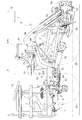
The direction indicated by the arrow F shown in FIG. 1 is the front side of the riding rice transplanter, and the direction indicated by the arrow U is the upper side of the riding rice transplanter.
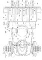
2 is the front side of the riding rice transplanter, and the direction indicated by the arrow R is the right side of the riding rice transplanter.
図1及び図2に示すように、本実施形態で例示する乗用田植機は、乗用型の4輪駆動形式に構成した走行車体1を備えている。そして、走行車体1の後下部に、平行リンク形式のリンク機構2を上下揺動可能に連結している。又、リンク機構2の後下部に、4条植え用の苗植付装置3をローリング可能に連結している。一方、走行車体1の後上部に、農用供給装置Aの一例として、圃場に対する供給物の一例である粒状肥料を圃場に供給する4条施肥用の施肥装置4を配備している。これにより、乗用田植機を、最大4条の苗植えと施肥とが可能な4条植え用のミッドマウント施肥仕様に構成している。そして、走行車体1の後部に、リンク機構2を介して苗植付装置3を昇降駆動する昇降シリンダ5を備えている。昇降シリンダ5には、単動型の油圧シリンダを採用している。
As shown in FIGS. 1 and 2, the riding rice transplanter exemplified in the present embodiment includes a traveling vehicle body 1 configured in a riding type four-wheel drive type. A parallel link
図1〜3に示すように、走行車体1は、車体フレーム6の前部にエンジン7などを備えている。又、車体フレーム6の後部側に搭乗運転部8などを備えている。車体フレーム6は、エンジン搭載用の前部フレーム9、前部フレーム9の後端部に連結するトランスミッションケース(以下、T/Mケースと称する)10、T/Mケース10の後端部に連結する後部フレーム11、及び、後部フレーム11の上端部に連結する座席フレーム12、などを備えている。搭乗運転部8は、前輪操舵用のステアリングホイール13、搭乗ステップ14、運転座席15、及び、後部ステップ16、などを備えている。
As shown in FIGS. 1 to 3, the traveling vehicle body 1 includes an engine 7 and the like at the front portion of the vehicle body frame 6. Further, a
図1及び図3に示すように、T/Mケース10は、その前側の左右両側部から横外方に延出する左右の前車軸ケース17、及び、その後側の左右両側部から後下方に延出する左右のスイングケース18、などを備えている。そして、左右の前車軸ケース17の延出端に、左右の前輪19を操舵可能かつ駆動可能に装備している。又、左右のスイングケース18の延出端に、左右の後輪20を駆動可能に装備している。左右のスイングケース18は、T/Mケース10から左右のスイングケース18にわたる左右向きの伝動軸21を支点にして上下揺動する。そして、それらの遊端側を左右のサスペンション機構22を介して車体フレーム6に連結している。
As shown in FIGS. 1 and 3, the T /
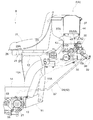
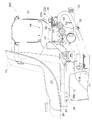
図1〜7に示すように、後部フレーム11は、T/Mケース10の後端部に連結することにより、上方に延出する後部フレーム11の支持部11Aが、T/Mケース10の後方に位置するように構成している。そして、支持部11Aの上面により、走行車体1の後上部に配備した後部ステップ16を下方から支持している。後部ステップ16は、左右の後輪20の車輪間隔よりも長い横幅を有している。そして、その左右の前端から搭乗ステップ14に向けて延出する後輪フェンダ兼用のカバー部16Aを一体形成している。
As shown in FIGS. 1 to 7, the
座席フレーム12は、後部ステップ16とともに後部フレーム11の上端部に連結して、後部ステップ16の上方に配備している。そして、座席フレーム12は、左右のクッションゴム23、及び、運転座席15の機体前後方向での位置調節を可能にする位置調節機構24を介して、走行車体1の後上部に配備した運転座席15を支持している。位置調節機構24は、座席フレーム12の前端部に着脱可能に備えた左右向きの支軸25、及び、運転座席15に備えた左右のブラケット26、などから構成している。そして、左右の各ブラケット26に、支軸挿通用の3つの貫通孔26Aを前後方向に所定間隔をあけて形成することにより、運転座席15の機体前後方向での3段階の位置調節を可能にしている。又、支軸25を支点にした運転座席15の使用位置と前方の倒伏位置とにわたる揺動操作を可能にしている。
The
図1に示すように、エンジン7からの動力は、ベルトテンション式の主クラッチ27などを介して、主変速装置として備えた静油圧式無段変速装置28に伝達している。そして、静油圧式無段変速装置28による変速後の動力を、T/Mケース10の内部において第1動力と第2動力とに分岐している。第1動力は、T/Mケース10に内蔵したギア式の副変速装置(図示せず)に伝達している。そして、副変速装置による変速後の第1動力を、T/Mケース10の内部において走行用と施肥用とに分岐している。走行用の動力は、T/Mケース10の内部において前輪駆動用と後輪駆動用とに分岐している。そして、前輪駆動用の動力を、前輪伝動系(図示せず)を介して左右の前輪19に伝達している。又、後輪駆動用の動力を、後輪伝動系(図示せず)を介して左右の後輪20に伝達している。施肥用の動力は、T/Mケース10に内蔵した施肥クラッチ(図示せず)などを介して施肥装置4に伝達している。第2動力は、T/Mケース10に内蔵したギア式の株間変速装置(図示せず)及び植付クラッチ(図示せず)などを介して、苗植え用として苗植付装置3に伝達している。植付クラッチは、その断続操作に連動して施肥クラッチが同様に断続操作されるように施肥クラッチに操作連係している。
As shown in FIG. 1, the power from the engine 7 is transmitted to a hydrostatic continuously
図1及び図2に示すように、苗植付装置3は、4条用の整地フロート30、4条用の苗載台31、動力分配機構32、横送り機構33、4基の植付機構34、及び、4条用の縦送り機構35、などを備えている。
As shown in FIGS. 1 and 2, the
整地フロート30は、作業走行時に走行車体1の走行に伴って圃場の泥面を整地しながら滑走する。苗載台31は、最大4条分のマット状苗を載置するように形成している。動力分配機構32は、走行車体1からの動力を、横送り機構33と各植付機構34と各縦送り機構35とに分配供給する。横送り機構33は、動力分配機構32からの動力により、苗載台31を左右方向に一定ストロークで往復移動させる。各植付機構34は、動力分配機構32からの動力により、苗載台31とともに左右方向に往復移動するマット状苗の下端から所定量ずつの植付苗を切り取って整地フロート30による整地後の圃場泥土部に植え付ける。各縦送り機構35は、苗載台31が左右のストローク端に達するごとに、動力分配機構32からの動力により、対応するマット状苗を苗載台31の下端に向けて所定ピッチで縦送りする。そして、これらの作動により、苗植付装置3を最大4条の苗植えが可能な4条用に構成している。
The leveling
図1〜6に示すように、施肥装置4は、施肥フレーム36、肥料貯留用のホッパ37、左右の繰出機構38、4本の施肥ホース39、4つの作溝器40、及び、電動式のブロワ41、などを備えている。そして、走行車体1の後部における運転座席15の機体後側に配備している。
As shown in FIGS. 1 to 6, the
施肥フレーム36は、左右の繰出機構38を後方から支持する左右に長い主部材42に、左右の繰出機構38を前方から支持する左右に長い補助部材43、などをボルト連結して構成している。
The
ホッパ37は、6条分の粒状肥料を貯留する横長形状に形成している。そして、ホッパ37は、その左右中心が機体の左右中心と一致する配置で、各繰出機構38及びブロワ41とともに走行車体1の後上部に配備している。ホッパ37の下端部には、3つの排出部37Aを左右方向に所定間隔をあけて備えている。そして、ホッパ37の内部に、ホッパ37の左右中央側に位置する排出部37Aへの粒状肥料の流下を阻止するとともに、ホッパ37の左右両端側に位置する排出部37Aに粒状肥料を流下案内するガイド部材44を着脱可能に備えている。つまり、6条用のホッパ37にガイド部材44を装着することにより、6条用のホッパ37を4条用に仕様変更している。
The
左右の繰出機構38は、それらの上端部をホッパ37の左右両端側に位置する排出部37Aに連結している。そして、左右の繰出機構38は、施肥フレーム36により連結している。又、左右の繰出機構38は、それらの内部に、走行車体1からの施肥用の動力によって回転する繰出ロール45を備えている。そして、各繰出ロール45の左半部に備えた複数の凹部45Aと右半部に備えた複数の凹部45Aとから、各繰出ロール45の回転により、ホッパ37の内部から2条分の粒状肥料を所定量ずつ下方に繰り出す2条用に構成している。これにより、最大4条分の粒状肥料を繰り出すように構成にしている。
The left and right feeding
各施肥ホース39は、それらの一端部を対応する繰出機構38に接続している。又、各施肥ホース39の他端部に作溝器40を接続している。これにより、各施肥ホース39は、各繰出機構38が繰り出した粒状肥料を対応する作溝器40に案内する。
Each
各作溝器40は、対応する植付機構34と機体横方向で隣接する位置に配置設定して整地フロート30に取り付けている。そして、各作溝器40は、作業走行時に、走行車体1の走行に伴って圃場の泥土部に施肥用の溝を形成し、その溝内に粒状肥料を埋没させる。
Each grooving
ブロワ41は、施肥フレーム36の左端部にボルト連結している。そして、ブロワ41は、走行車体1からの電力で作動することにより、各繰出機構38から各施肥ホース39の内部を通って各作溝器40に向かう搬送風を生起する。これにより、各繰出機構38が繰り出した粒状肥料の各施肥ホース内での流動を円滑にすることができる。
The
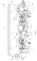
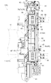
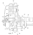
図1〜8に示すように、施肥装置4は、左右の繰出機構38にわたる左右向きの駆動軸48、走行車体1からの施肥用の動力を駆動軸48に伝達する繰出用伝動機構49、及び、各繰出機構38による肥料繰り出し量の一括した調節を可能にする繰出量調節機構50、などを備えている。
As shown in FIGS. 1 to 8, the
駆動軸48は、断面が正六角形の六角軸により構成している。そして、駆動軸48は、各繰出機構38に備えた入力ギア51と噛み合い連動する2つの出力ギア52を相対回転可能に外嵌装備している。又、駆動軸48は、駆動軸48から対応する出力ギア52への伝動を断続する2つの施肥条数切替クラッチ53を外嵌装備している。各施肥条数切替クラッチ53は、搭乗運転部8に備えた2本の条数切替レバー54に2系統の施肥条数切替操作系55を介して操作連係している。これにより、各施肥条数切替クラッチ53は、対応する条数切替レバー54による断続操作を可能にしている。
The
一方、苗植付装置3は、動力分配機構32から対応する2つの植付機構34への伝動を断続する2つの植付条数切替クラッチ56、及び、動力分配機構32から対応する2つの縦送り機構35への伝動を断続する2つの縦送り条数切替クラッチ57、を備えている。各植付条数切替クラッチ56は、対応する条数切替レバー54に2系統の植付条数切替操作系58を介して操作連係している。これにより、各植付条数切替クラッチ56は、対応する条数切替レバー54による断続操作を可能にしている。各縦送り条数切替クラッチ57は、対応する条数切替レバー54に2系統の縦送り条数切替操作系59を介して操作連係している。これにより、各縦送り条数切替クラッチ57は、対応する条数切替レバー54による断続操作を可能にしている。
On the other hand, the
上記の構成から、各条数切替レバー54の操作により、この乗用田植機の作業状態を、苗植付装置3における全ての植付機構34と縦送り機構35とを作動させ、かつ、施肥装置4における全ての繰出機構38を作動させる全条作業状態、苗植付装置3における左側2条分の植付機構34と縦送り機構35とを作動させ、かつ、施肥装置4における左側の繰出機構38を作動させる左側2条作業状態、苗植付装置3における右側2条分の植付機構34と縦送り機構35とを作動させ、かつ、施肥装置4における右側の繰出機構38を作動させる右側2条作業状態、又は、苗植付装置3における全ての植付機構34と縦送り機構35とを停止させ、かつ、施肥装置4における全ての繰出機構38を停止させる全条停止状態に、択一的に切り替えることができる。
From the above configuration, by operating each row
図5、図6、図8及び図9に示すように、施肥装置4は、各繰出機構38を停止状態に一括して切り替える施肥停止用の切替レバー60を備えている。切替レバー60は、施肥フレーム36の右端部に、停止位置と停止解除位置とに揺動切り替え可能に配備している。そして、切替レバー60は、左右向きの連係部材61などを備える施肥状態切替操作系62を介して各施肥条数切替クラッチ53に操作連係している。これにより、切替レバー60の停止解除位置から停止位置への揺動操作に伴って、各繰出機構38が、各条数切替レバー54の操作位置にかかわらず停止状態に切り替わるように構成している。又、切替レバー60の停止位置から停止解除位置への揺動操作に伴って、各繰出機構38が、対応する条数切替レバー54の操作位置に応じた作動状態に切り替わるように構成している。
As shown in FIGS. 5, 6, 8, and 9, the
つまり、施肥停止用の切替レバー60を揺動操作することにより、この乗用田植機の作業状態を、苗植付装置3による苗植えと施肥装置4による施肥とを行う植え付け施肥状態と、施肥装置4による施肥を行わずに苗植付装置3による苗植えのみを行う植え付け状態とに切り替えることができる。
That is, by swinging the switching
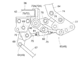
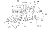
図1、図3〜5及び図9〜18に示すように、繰出用伝動機構49は、T/Mケース10の左側部に備えた左右向きの施肥動力取出軸63が施肥用の動力として出力する回転動力を往復揺動運動に変換する第1変換部64、及び、その往復揺動運動を駆動軸48の正回転運動に変換する第2変換部65、などを備えている。そして、前述した繰出量調節機構50に連係する第2変換部65を、繰出量調節機構50とともに機体の右端部に配備している。
As shown in FIGS. 1, 3 to 5, and FIGS. 9 to 18, the feeding
第1変換部64は、施肥動力取出軸63と一体回転する回転アーム66に一端部をピン連結した連係ロッド67、連係ロッド67の他端部にピン連結した第1アーム68、第1アーム68を左端部に固着した左右向きの連係軸69、及び、第1アーム68と連係軸69を介して一体揺動するように連係軸69の右端部に固着した第2アーム70、などを備えている。そして、これらにより、第1変換部64は、施肥動力取出軸63からの回転動力を第1アーム68及び第2アーム70の往復揺動運動に変換している。
The
駆動軸48は、その最右端部に駆動軸48の逆回転を防止する逆転防止用のワンウェイクラッチ71を外嵌装備している。逆転防止用のワンウェイクラッチ71は、その外輪71Aを施肥フレーム36の主部材42にボルト連結して固定している。
The
第2変換部65は、駆動軸48の正回転操作を可能にする正回転操作用の第1ワンウェイクラッチ72と第2ワンウェイクラッチ73、第1変換部64における第2アーム70の往方向の揺動運動(機体後方への揺動運動)を左側の第1ワンウェイクラッチ72を介して駆動軸48の正回転動力として駆動軸48に伝える第1リンク機構74、及び、第1変換部64における第2アーム70の復方向の揺動運動(機体前方への揺動運動)を右側の第2ワンウェイクラッチ73を介して駆動軸48の正回転動力として駆動軸48に伝える第2リンク機構75、などを備えている。
The
第1ワンウェイクラッチ72及び第2ワンウェイクラッチ73は、駆動軸48の右端部における逆転防止用のワンウェイクラッチ71よりも機体内側の位置に、左右に並べた状態で外嵌装備している。
The first one-way clutch 72 and the second one-way clutch 73 are externally fitted to the right end portion of the
第1リンク機構74は、第2アーム70に一端部をピン連結したターンバックル式の連係ロッド76、連係ロッド76の他端部にピン連結した揺動部材77、揺動部材77に一端部をピン連結した第1連係部材78、及び、第1連係部材78の他端部にピン連結した第1揺動リンク79、などにより構成している。
The
第2リンク機構75は、第1リンク機構74と共用する連係ロッド76と揺動部材77、揺動部材77に一端部をピン連結した第2連係部材80、及び、第2連係部材80の他端部にピン連結した第2揺動リンク81、などにより構成している。
The
第1揺動リンク79は、その基端部を第1ワンウェイクラッチ72の外輪72Aに固着している。第2揺動リンク81は、その基端部を第2ワンウェイクラッチ73の外輪73Aに固着している。これにより、第2リンク機構75の第2連係部材80及び第2揺動リンク81が、第1リンク機構74の第1連係部材78及び第1揺動リンク79よりも機体の右外側に位置するように構成している。
The
第2リンク機構75は、駆動軸48に伝動する伝動状態と伝動を停止する伝動停止状態とに切り替え可能に構成している。この構成により、第2リンク機構75を伝動状態に切り替えると、第1変換部64における第2アーム70の往方向の揺動運動と復方向の揺動運動とを第2変換部65を介して駆動軸48の正回転動力として伝えることができる。これにより、第2アーム70の往復揺動から得られる各繰出機構38における繰出ロール45の回動角を大きくすることができ、第2アーム70の1往復揺動当たりでの各繰出機構38による肥料繰出量を多くすることができる。逆に、第2リンク機構75を伝動停止状態に切り替えると、第1変換部64における第2アーム70の往方向の揺動運動のみを第2変換部65を介して駆動軸48の正回転動力として伝えることができる。これにより、第2アーム70の往復揺動から得られる各繰出機構38における繰出ロール45の回動角を小さくすることができ、第2アーム70の1往復揺動当たりでの各繰出機構38による肥料繰出量を少なくすることができる。
The
つまり、第2リンク機構75を伝動状態と伝動停止状態とに切り替えることにより、各繰出機構38の肥料繰り出し状態を、第2アーム70の1往復揺動当たりの肥料繰り出し量を標準量とする第1繰り出し状態と、第2アーム70の1往復揺動当たりの肥料繰り出し量を標準量よりも少なくする第2繰り出し状態とに切り替えることができ、施肥装置4の作動状態を、標準量の施肥を行う標準施肥状態と、標準量よりも施肥量の少ない施肥を行う減量施肥状態とに切り替えることができる。
That is, by switching the
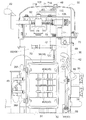
図2、図4〜6及び図9〜18に示すように、繰出量調節機構50は、上下揺動可能な前後向きのネジ軸82、ネジ軸82の前端に固定した人為操作用のハンドル83、及び、ネジ軸82を第2変換部65の揺動部材77に連係する連係アーム84、などを備えている。
As shown in FIGS. 2, 4 to 6, and FIGS. 9 to 18, the feed
そして、ハンドル83を減量方向に回転させると、ネジ軸82によるネジ送り作用により、連係アーム84が減量方向に揺動変位し、この揺動変位に伴って、第2変換部65の揺動部材77が減量方向に揺動変位する。これにより、揺動部材77と正回転操作用の各ワンウェイクラッチ72,73とを連係する連係部材78,80と揺動リンク79,81との屈曲が浅くなり、揺動部材77の揺動角に対する揺動リンク79,81の揺動角が小さくなる。その結果、施肥装置4の各繰出機構38による肥料繰り出し量を一括して減少させることができる。
Then, when the
逆に、ハンドル83を増量方向に回転させると、ネジ軸82によるネジ送り作用により、連係アーム84が増量方向に揺動変位し、この揺動変位に伴って、第2変換部65の揺動部材77が増量方向に揺動変位する。これにより、揺動部材77と正回転操作用の各ワンウェイクラッチ72,73とを連係する連係部材78,80と揺動リンク79,81との屈曲が深くなり、揺動部材77の揺動角に対する揺動リンク79,81の揺動角が大きくなる。その結果、施肥装置4の各繰出機構38による肥料繰り出し量を一括して増加させることができる。
On the contrary, when the
つまり、繰出量調節機構50は、ネジ軸82のネジ送り作用により、各繰出機構38による肥料繰り出し量を一括して無段階に調節するネジ送り調節式に構成している。
That is, the feed
第2変換部65は、施肥装置4の標準施肥状態での各繰出機構38の肥料繰り出し量を繰出量調節機構50にて最少に設定した場合と、施肥装置4の減量施肥状態での各繰出機構38の肥料繰り出し量を繰出量調節機構50にて最多に設定した場合とで、第1変換部64における第2アーム70の1回の往復揺動に対する駆動軸48の正回転方向での回転角が同じになって各繰出機構38の肥料繰り出し量が同じになるように、第1リンク機構74及び第2リンク機構75のリンク比を設定している。
The
これにより、施肥装置4の標準施肥状態での繰出量調節機構50による肥料繰り出し量の調節領域と、施肥装置4の減量施肥状態での繰出量調節機構50による肥料繰り出し量の調節領域とに、肥料繰り出し量が重複する無駄な調節領域が存在することを阻止している。その結果、施肥装置4の標準施肥状態と減量施肥状態との切り替えを利用した繰出量調節機構50による肥料繰り出し量の調節を、無駄なく連続する広範囲の調節領域によって良好に行うことができる。
Thereby, in the adjustment area | region of the fertilizer feed amount by the feed
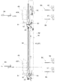
図9及び図11〜13に示すように、逆転防止用のワンウェイクラッチ71は、その外輪71Aに施肥フレーム36の主部材42に対する連結部71Bを備えている。施肥フレーム36の主部材42は、ワンウェイクラッチ71の連結部71Bとのボルト連結を可能にする連結部42Aを備えている。主部材42の連結部42Aとワンウェイクラッチ71の連結部71Bとの連結には、2本の段付きボルト103と2つの座金104と2つのバネ座金105とを使用している。そして、ワンウェイクラッチ71の連結部71Bにおける穴径を、段付きボルト103の大径部103Aよりも大きくして、ワンウェイクラッチ71の連結部71Bを、主部材42の連結部42Aと段付きボルト103の頭部103Bとの間に、座金104とバネ座金105とを介して挟持保持するように構成している。
As shown in FIGS. 9 and 11 to 13, the one-way clutch 71 for preventing reverse rotation includes a connecting
図1〜3、図5、図6及び図9〜19に示すように、この乗用田植機は、走行車体1からの施肥用の動力を、3つのワンウェイクラッチ71〜73などを備える繰出用伝動機構49を介して駆動軸48に伝達している。3つのワンウェイクラッチ71〜73は、駆動軸48の右端部に係合装備した左右のC形の止め輪100の間に、左右方向に並べた状態で外嵌装備している。そして、隣接するワンウェイクラッチ71〜73の間にスペーサ101を介装している。
As shown in FIGS. 1 to 3, 5, 6, and 9 to 19, the riding rice transplanter uses the power for fertilization from the traveling vehicle body 1 as a transmission for transmission including three one-
図12、図13及び図19〜22に示すように、各ワンウェイクラッチ71〜73は、駆動軸48に外嵌する内輪71C〜73Cを備えている。各内輪71C〜73Cは、駆動軸48の断面と同じ正六角形の嵌合孔71Ca〜73Caを有する小径部71Cb〜73Cbと、駆動軸48の外接円よりも大径の丸孔71Cc〜73Ccを有する拡径部71Cd〜73Cdとを備えている。各ワンウェイクラッチ71〜73は、各内輪71C〜73Cの小径部71Cb〜73Cbが各外輪71A〜73Aに内嵌し、各内輪71C〜73Cの拡径部71Cd〜73Cdが、各外輪71A〜73Aの横外側に食み出すように構成している。そして、各内輪71C〜73Cは、拡径部71Cd〜73Cdの外径が、各ワンウェイクラッチ71〜73の外輪71A〜73Aと内輪71C〜73Cとの間に介装するオイルシール102の外径と略同じ大きさになるように形成している。
As shown in FIGS. 12, 13, and 19 to 22, each one-way clutch 71 to 73 includes
繰出用伝動機構49は、各ワンウェイクラッチ71〜73に備えた内輪71C〜73Cの拡径部71Cd〜73Cdと駆動軸48との間に圧入する樹脂製の筒状体110を備えている。そして、各筒状体110を、駆動軸48と各内輪71C〜73Cの拡径部71Cd〜73Cdとの間に圧入することにより、駆動軸48及び各ワンウェイクラッチ71〜73の個体差に起因して生じる虞のある駆動軸48と各内輪71C〜73Cとの間でのガタツキを解消することができ、このガタツキに起因して発生する駆動軸48と各ワンウェイクラッチ71〜73との間での伝動ロスを無くすことができる。
The feeding
これにより、複数の乗用田植機を製造する場合に、走行車体1からの動力が同じであるにもかかわらず、駆動軸48と各ワンウェイクラッチ71〜73との間に生じる伝動ロスに起因して、各乗用田植機に備える施肥装置4ごとに、3つワンウェイクラッチ71〜73を介して得られる駆動軸48の回転数に差が生じる虞を回避することができる。
Thereby, when manufacturing a plurality of riding rice transplanters, the power from the traveling vehicle body 1 is the same, but due to the transmission loss that occurs between the
その結果、各乗用田植機に備える施肥装置4からの肥料繰り出し量が、各乗用田植機に備える施肥装置4ごとに異なる不具合が生じる虞を回避することができる。
As a result, it is possible to avoid a possibility that the amount of fertilizer fed from the
又、各ワンウェイクラッチ71〜73の内輪71C〜73Cが、前述した小径部71Cb〜73Cbと拡径部71Cd〜73Cdとを備えることにより、例えば、各内輪71C〜73Cの全体を拡径して、駆動軸48と各内輪71C〜73Cとの間に、各内輪71C〜73Cの全体にわたる長さを有する筒状体110を圧入する場合に比較して、各ワンウェイクラッチ71〜73の径方向での大型化を抑制することができる。
Further, the
しかも、駆動軸48と各内輪71C〜73Cの拡径部71Cd〜73Cdとの間に各筒状体110を圧入することにより、各内輪71C〜73Cと各筒状体110との接触面積を大きくすることができる。これにより、各ワンウェイクラッチ71〜73の内輪71C〜73Cと各筒状体110との間での滑りの発生を効果的に抑制することができ、各ワンウェイクラッチ71〜73の内輪71C〜73Cと各筒状体110との間での滑りに起因した伝動ロスの発生を効果的に抑制することができる。
Moreover, by pressing the
ところで、例えば筒状体110を単一の筒状部材で構成すると、筒状体110を駆動軸48と各内輪71C〜73Cの拡径部71Cd〜73Cdとの間に圧入する場合には、筒状体110を駆動軸48の右端部に外嵌した後、筒状体110を駆動軸48の右端部から圧入箇所まで摺動移動させる必要がある。そのため、駆動軸48と各内輪71C〜73Cとの間への筒状体110の圧入に手間を要することになる。又、筒状体110の摺動移動中に、筒状体110の内周面が、駆動軸48の角部48A、又は、駆動軸48に形成した止め輪用の係合溝48C、などに摺接することにより傷付く虞がある。
By the way, for example, when the
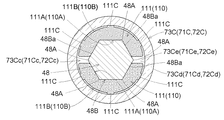
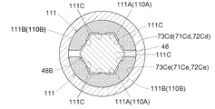
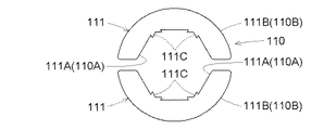
そこで、図20〜22に示すように、各筒状体110を、断面が正六角形の駆動軸48に対して駆動軸48の対向する2つの角部48Aを挟む状態で配置する2つの湾曲部材111により筒状に構成している。
Therefore, as shown in FIGS. 20 to 22, the two curved members are arranged so that each
これにより、各湾曲部材111を、駆動軸48と各内輪71C〜73Cの拡径部71Cd〜73Cdとの間に圧入することにより、筒状体110を駆動軸48の右端部に外嵌する手間や、駆動軸48の右端部から圧入箇所まで筒状体110を摺動移動させる手間を要することなく、筒状体110を駆動軸48と各内輪71C〜73Cの拡径部71Cd〜73Cdとの間に圧入することができる。
Accordingly, it is troublesome to externally fit the
又、筒状体110を駆動軸48に外嵌した状態で摺動移動させる必要がないことから、筒状体110の摺動移動中に、筒状体110の内周面110Aが、駆動軸48の角部48A、又は、駆動軸48に形成した止め輪用の係合溝48C、などに摺接することに起因して傷付く虞を回避することができる。
Further, since it is not necessary to slide the
図20〜22に示すように、各湾曲部材111は、駆動軸48の外周面48Bに沿う内面111A、及び、各拡径部71Cd〜73Cdの内周面71Ce〜73Ceに沿って湾曲する外面111Bを備えている。そして、対になる2つの湾曲部材111の内面111Aにより、筒状体110の内周面110Aを形成している。又、対になる2つの湾曲部材111の外面111Bにより、筒状体110の外周面110Bを形成している。
As shown in FIGS. 20 to 22, each bending
各湾曲部材111は、それらの外面111Bにおける駆動軸48の角部48Aとの対向部位から外れた位置において、駆動軸48の軸心方向に延びる3本の突条111Cを備えている。又、各湾曲部材111の内面111Aを、駆動軸48の外周面48Bを形成する6面の平面部48Baのうちの3面に面接触する3面の平面部111Aaにより形成している。
Each of the bending
つまり、各湾曲部材111の外面111Bに、駆動軸48の軸心方向に延びる3本の突条111Cを備えることにより、駆動軸48と各内輪71C〜73Cの拡径部71Cd〜73Cdとの間への各湾曲部材111の圧入が行い易くなる。そして、駆動軸48と各内輪71C〜73Cの拡径部71Cd〜73Cdとの間に各湾曲部材111を圧入すると、各湾曲部材111の外面111Bに備えた各突条111Cが各内輪71C〜73Cにおける拡径部71Cd〜73Cdの内周面71Ce〜73Ceに圧接するのに伴って、各湾曲部材111の内面111Aを形成する3面の平面部111Aaが、駆動軸側に押し出されて、駆動軸48の外周面48Bを形成する6面の平面部48Baに密接するようになる。
In other words, by providing the
その結果、駆動軸48と各内輪71C〜73Cの拡径部71Cd〜73Cdとの間への各湾曲部材111の圧入を行い易くしながら、駆動軸48及び各ワンウェイクラッチ71〜73の個体差に起因して生じる虞のある駆動軸48と各内輪71C〜73Cとの間でのガタツキをより確実に解消することができる。
As a result, individual differences between the
又、各湾曲部材111の内面111Aを形成する3面の平面部111Aaが120度の挟角を有することから、各湾曲部材111が、それらの内面111Aに30度の抜き勾配を有することになる。これにより、各湾曲部材111の内面側に専用の抜き勾配を備えることなく、各湾曲部材111を成型した後の型抜きを容易にすることができる。
In addition, since the three plane portions 111Aa forming the
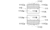
図22に示すように、各湾曲部材111の各突条111Cは、それらの駆動軸48の軸心方向での両端部111Caが、駆動軸48の軸心方向での両端側ほど外方への突出量が少なくなる状態で傾斜している。
As shown in FIG. 22, each
これにより、駆動軸48と各内輪71C〜73Cの拡径部71Cd〜73Cdとの間に各湾曲部材111を圧入するときには、各湾曲部材111の向きに関係なく、駆動軸48と各内輪71C〜73Cの拡径部71Cd〜73Cdとの間への各湾曲部材111の圧入を更に行い易くすることができる。
As a result, when the
〔別実施形態〕 [Another embodiment]
〔1〕農用供給装置Aは、例えば、走行車体1からの動力を苗縦送り用の駆動軸に伝達する苗縦送り用のワンウェイクラッチを備えた苗植付装置、走行車体1からの動力を種繰り出し用の駆動軸に伝達する種繰り出し用のワンウェイクラッチを備えた直播装置、又は、走行車体1からの動力を薬剤繰り出し用の駆動軸に伝達する薬剤繰り出し用のワンウェイクラッチを備えた薬剤散布装置、などであってもよい。 [1] Agricultural supply device A, for example, a seedling planting device provided with a one-way clutch for vertical seedling feeding that transmits power from traveling vehicle body 1 to a drive shaft for vertical seedling feeding, and power from traveling vehicle body 1 Direct seeding device equipped with a one-way clutch for seed feeding that transmits to a drive shaft for seed feeding, or medicine spraying equipped with a one-way clutch for medicine feeding that transmits the power from the traveling vehicle body 1 to the driving shaft for drug delivery It may be a device.
〔2〕農用供給装置Aの作業条数は、例えば5条以上であってもよい。又、農用供給装置Aに備えるワンウェイクラッチ71〜73の数量は、農用供給装置Aの種類又は構成などに応じて種々の変更が可能である。例えば、農用供給装置Aに単一のワンウェイクラッチ72を備えるようにしてもよい。
[2] The number of working strips of the agricultural supply apparatus A may be five or more, for example. The number of the one-
〔3〕走行車体1の構成は種々の変更が可能である。例えば、走行車体1を、左右のスイングケース18に代えて、固定式の後車軸ケースを備えるように構成してもよい。又、走行車体1を、運転座席15の下方にエンジン7を備えるように構成してもよい。
[3] The configuration of the traveling vehicle body 1 can be variously changed. For example, the traveling vehicle body 1 may be configured to include a fixed rear axle case instead of the left and
〔4〕駆動軸48に採用する角軸は種々の変更が可能である。例えば、断面形状が正方形、正五角形、又は、正八角形、などの角軸を駆動軸48に採用してもよい。
[4] The angular axis employed for the
〔5〕ワンウェイクラッチ71〜73の内輪71C〜73Cを、駆動軸48の軸心方向での内輪71C〜73Cの全長にわたって、駆動軸48の外接円よりも大径の丸孔71Cc〜73Ccを有するように形成し、筒状体110を、駆動軸48と内輪71C〜73Cとの間に、駆動軸48の軸心方向での内輪71C〜73Cの全長にわたって圧入するように構成してもよい。
[5] The inner rings 71C to 73C of the one-
〔6〕ワンウェイクラッチ71〜73の内輪71C〜73Cを、内輪71C〜73Cの両端部に拡径部71Cd〜73Cdを有するように形成して、駆動軸48と内輪71C〜73Cの両端部(拡径部71Cd〜73Cd)との間に、筒状体110を圧入するように構成してもよい。
[6] The inner rings 71C to 73C of the one-
〔7〕図23〜25に示すように、筒状体110の内周面110A(湾曲部材111の内面111A)に駆動軸48の軸心方向に延びる3本の突条111Cを備え、筒状体110の外周(湾曲部材111の外面111B)を、ワンウェイクラッチ71〜73に備えた内輪71C〜73Cの内周と同じ形状で、内輪71C〜73Cの内周面71Ce〜73Ceに面接触可能に形成し、筒状体110(湾曲部材111)の圧入状態では、突条111Cのそれぞれが駆動軸48の外周面48Bに圧接し、かつ、筒状体110の外周面110B(湾曲部材111の外面111B)が内輪71C〜73Cの内周面71Ce〜73Ceに圧接するように構成してもよい。そして、筒状体110(湾曲部材111)の各突条111Cを、それらの駆動軸48の軸心方向での両端部111Caが、駆動軸48の軸心方向での両端側ほど外方への突出量が少なくなる状態で傾斜するように形成してもよい。
[7] As shown in FIGS. 23 to 25, the inner
〔8〕図26及び図27に示すように、筒状体110の内周面110A(湾曲部材111の内面111A)に駆動軸48の軸心方向に延びる2本の突条111Cを備え、筒状体110の外周(湾曲部材111の外面111B)を、ワンウェイクラッチ71〜73に備えた内輪71C〜73Cの内周と同じ形状で、内輪71C〜73Cの内周面71Ce〜73Ceに面接触可能に形成し、筒状体110(湾曲部材111)の圧入状態では、突条111Cのそれぞれが駆動軸48の角部48Aに圧接し、かつ、筒状体110の外周面110Bが内輪71C〜73Cの内周面71Ce〜73Ceに圧接するように構成してもよい。そして、図示は省略するが、この構成においても、筒状体110(湾曲部材111)の各突条111Cを、それらの駆動軸48の軸心方向での両端部111Caが、駆動軸48の軸心方向での両端側ほど外方への突出量が少なくなる状態で傾斜するように形成してもよい。
[8] As shown in FIGS. 26 and 27, the inner
〔9〕筒状体110(湾曲部材111)に備える各突条111Cを、それらの駆動軸48の軸心方向での一端部のみが、駆動軸48の軸心方向での一端側ほど外方への突出量が少なくなる状態で傾斜するように形成してもよい。又、各突条111Cを、それらの駆動軸48の軸心方向での両端にわたって、外方への突出量が一定になるように形成してもよい。
[9] Each
〔10〕筒状体110(湾曲部材111)に備える突条111Cの数量及び配置は、駆動軸48の断面形状などに応じて種々の変更が可能である。例えば、筒状体110の外周面110B(湾曲部材111の外面111B)における駆動軸48の角部48Aとの対向部位と、角部48Aとの対向部位から外れた位置とのそれぞれに、駆動軸48の軸心方向に延びる複数の突条111Cを備えるようにしてもよい。又、筒状体110の内周面110A(湾曲部材111の内面111A)における駆動軸48の角部48Aとの対向部位と、角部48Aとの対向部位から外れた位置とのそれぞれに、駆動軸48の軸心方向に延びる複数の突条111Cを備えるようにしてもよい。
[10] The number and arrangement of the
〔11〕筒状体110(湾曲部材111)を、筒状体110の内周面110A(湾曲部材111の内面111A)と、筒状体110の外周面110B(湾曲部材111の外面111B)との双方に複数の突条111Cを有するように形成してもよい。又、筒状体110(湾曲部材111)を、筒状体110の内周面110A(湾曲部材111の内面111A)と、筒状体110の外周面110B(湾曲部材111の外面111B)とのいずれにも突条111Cを有しないように形成してもよい。
[11] The cylindrical body 110 (curved member 111) is made up of an inner
〔12〕筒状体110を、単一の筒状部材により構成してもよい。又、筒状体110を、3つ以上の湾曲部材111により筒状に構成してもよい。
[12] The
〔13〕図28に示すように、駆動軸48に圧接状態で外嵌する小径部120Aと、ワンウェイクラッチ71〜73の内輪71C〜73Cに圧接状態で外嵌する大径部120Bとを有する樹脂製の筒状体120を備えて、駆動軸48及び各ワンウェイクラッチ71〜73の個体差に起因して発生する駆動軸48と各内輪71C〜73Cとの間でのガタツキを解消するように構成してもよい。
[13] As shown in FIG. 28, a resin having a small-
本発明は、走行車体からの動力を駆動軸に伝達するワンウェイクラッチを備えた、例えば、苗植付装置、直播装置、施肥装置、薬剤散布装置、などの農用供給装置に適用することができる。 The present invention can be applied to agricultural supply devices such as a seedling planting device, a direct sowing device, a fertilizer application device, and a medicine spraying device that include a one-way clutch that transmits power from a traveling vehicle body to a drive shaft.
1 走行車体
48 駆動軸
48A 角部
48B 外周面
71 ワンウェイクラッチ
71C 内輪
71Ca 嵌合孔
71Cb 小径部
71Cc 丸孔
71Cd 拡径部
71Ce 内周面
72 ワンウェイクラッチ
72C 内輪
72Ca 嵌合孔
72Cb 小径部
72Cc 丸孔
72Cd 拡径部
72Ce 内周面
73 ワンウェイクラッチ
73C 内輪
73Ca 嵌合孔
73Cb 小径部
73Cc 丸孔
73Cd 拡径部
73Ce 内周面
110 筒状体
110A 内周面
110B 外周面
111 湾曲部材
111A 内面
111Aa 平面部
111C 突条
111Ca 両端部
1 traveling
Claims (9)
前記駆動軸を断面多角形の角軸により構成し、
前記ワンウェイクラッチは、前記駆動軸に外嵌する内輪を備え、
前記駆動軸と前記内輪との間に樹脂製の筒状体を圧入している農用供給装置。 With a one-way clutch that transmits the power from the traveling vehicle body to the drive shaft,
The drive shaft is constituted by an angular axis having a polygonal cross section,
The one-way clutch includes an inner ring that is externally fitted to the drive shaft,
An agricultural supply apparatus in which a cylindrical body made of resin is press-fitted between the drive shaft and the inner ring.
前記駆動軸を断面多角形の角軸により構成し、
前記ワンウェイクラッチは、前記駆動軸に外嵌する内輪を備え、
前記駆動軸と前記内輪との間に樹脂製の筒状体を圧入し、
前記筒状体を、複数の湾曲部材により筒状に構成している農用供給装置。 With a one-way clutch that transmits the power from the traveling vehicle body to the drive shaft,
The drive shaft is constituted by an angular axis having a polygonal cross section,
The one-way clutch includes an inner ring that is externally fitted to the drive shaft,
Press-fit a resin cylindrical body between the drive shaft and the inner ring,
The agricultural supply apparatus which comprises the said cylindrical body in the cylinder shape by the some bending member.
前記駆動軸を断面多角形の角軸により構成し、
前記ワンウェイクラッチは、前記駆動軸に外嵌する内輪を備え、
前記内輪は、前記駆動軸の断面と同じ多角形の嵌合孔を有する小径部と、前記駆動軸の外接円よりも大径の丸孔を有する拡径部とを備え、
前記駆動軸と前記拡径部との間に樹脂製の筒状体を圧入している農用供給装置。 With a one-way clutch that transmits the power from the traveling vehicle body to the drive shaft,
The drive shaft is constituted by an angular axis having a polygonal cross section,
The one-way clutch includes an inner ring that is externally fitted to the drive shaft,
The inner ring includes a small-diameter portion having a polygonal fitting hole that is the same as the cross-section of the drive shaft, and an enlarged-diameter portion having a round hole larger in diameter than a circumscribed circle of the drive shaft,
An agricultural supply apparatus in which a cylindrical body made of resin is press-fitted between the drive shaft and the enlarged diameter portion.
前記駆動軸を断面多角形の角軸により構成し、
前記ワンウェイクラッチは、前記駆動軸に外嵌する内輪を備え、
前記内輪は、前記駆動軸の断面と同じ多角形の嵌合孔を有する小径部と、前記駆動軸の外接円よりも大径の丸孔を有する拡径部とを備え、
前記駆動軸と前記拡径部との間に樹脂製の筒状体を圧入し、
前記筒状体を、複数の湾曲部材により筒状に構成している農用供給装置。 With a one-way clutch that transmits the power from the traveling vehicle body to the drive shaft,
The drive shaft is constituted by an angular axis having a polygonal cross section,
The one-way clutch includes an inner ring that is externally fitted to the drive shaft,
The inner ring includes a small-diameter portion having a polygonal fitting hole that is the same as the cross-section of the drive shaft, and an enlarged-diameter portion having a round hole larger in diameter than a circumscribed circle of the drive shaft,
Press-fit a resin cylindrical body between the drive shaft and the enlarged diameter portion,
The agricultural supply apparatus which comprises the said cylindrical body in the cylinder shape by the some bending member.
前記筒状体の外周面における前記駆動軸の角部との対向部位から外れた位置に、前記駆動軸の軸心方向に延びる複数の突条を備え、
前記筒状体の圧入状態では、前記突条のそれぞれが前記内輪の内周面に圧接し、かつ、前記筒状体の内周面が前記駆動軸の外周面に圧接している請求項1〜4のいずれか一つに記載の農用供給装置。 The inner periphery of the cylindrical body is formed in the same polygon as the cross-sectional shape of the drive shaft so as to be in surface contact with the outer peripheral surface of the drive shaft,
A plurality of ridges extending in the axial direction of the drive shaft at a position deviating from a portion facing the corner of the drive shaft on the outer peripheral surface of the cylindrical body;
2. In the press-fitted state of the cylindrical body, each of the protrusions is in pressure contact with the inner peripheral surface of the inner ring, and the inner peripheral surface of the cylindrical body is in pressure contact with the outer peripheral surface of the drive shaft. The agricultural supply apparatus as described in any one of -4.
前記筒状体の外周面における前記駆動軸の角部との対向部位から外れた位置に、前記駆動軸の軸心方向に延びる複数の突条を備え、
前記筒状体の圧入状態では、前記突条のそれぞれが前記内輪の内周面に圧接し、かつ、前記筒状体の内周面が前記駆動軸の外周面に圧接し、
前記突条のそれぞれは、前記軸心方向での両端側ほど外方への突出量が少なくなる状態で両端部が傾斜している請求項1〜4のいずれか一つに記載の農用供給装置。 The inner periphery of the cylindrical body is formed in the same polygon as the cross-sectional shape of the drive shaft so as to be in surface contact with the outer peripheral surface of the drive shaft,
A plurality of ridges extending in the axial direction of the drive shaft at a position deviating from a portion facing the corner of the drive shaft on the outer peripheral surface of the cylindrical body;
In the press-fitted state of the cylindrical body, each of the protrusions presses against the inner peripheral surface of the inner ring, and the inner peripheral surface of the cylindrical body presses against the outer peripheral surface of the drive shaft,
The agricultural supply device according to any one of claims 1 to 4, wherein each of the protrusions is inclined at both ends in a state where the outward protrusion amount decreases toward both ends in the axial direction. .
前記筒状体の外周を、前記内輪の内周と同じ形状で、前記内輪の内周面に面接触可能に形成し、
前記筒状体の圧入状態では、前記突条のそれぞれが前記駆動軸の外周面に圧接し、かつ、前記筒状体の外周面が前記内輪の内周面に圧接している請求項1〜4のいずれか一つに記載の農用供給装置。 Provided with a plurality of protrusions extending in the axial direction of the drive shaft on the inner peripheral surface of the cylindrical body,
The outer periphery of the cylindrical body is formed in the same shape as the inner periphery of the inner ring so as to be in surface contact with the inner peripheral surface of the inner ring,
Each of the said protrusions press-contacts with the outer peripheral surface of the said drive shaft in the press-fit state of the said cylindrical body, and the outer peripheral surface of the said cylindrical body is press-contacted with the internal peripheral surface of the said inner ring | wheel. The agricultural supply apparatus according to any one of 4.
前記筒状体の外周を、前記内輪の内周と同じ形状で、前記内輪の内周面に面接触可能に形成し、
前記筒状体の圧入状態では、前記突条のそれぞれが前記駆動軸の外周面に圧接し、かつ、前記筒状体の外周面が前記内輪の内周面に圧接し、
前記突条のそれぞれは、前記軸心方向での両端側ほど外方への突出量が少なくなる状態で両端部が傾斜している請求項1〜4のいずれか一つに記載の農用供給装置。 Provided with a plurality of protrusions extending in the axial direction of the drive shaft on the inner peripheral surface of the cylindrical body,
The outer periphery of the cylindrical body is formed in the same shape as the inner periphery of the inner ring so as to be in surface contact with the inner peripheral surface of the inner ring,
In the press-fitted state of the cylindrical body, each of the protrusions presses against the outer peripheral surface of the drive shaft, and the outer peripheral surface of the cylindrical body presses against the inner peripheral surface of the inner ring,
The agricultural supply device according to any one of claims 1 to 4, wherein each of the protrusions is inclined at both ends in a state where the outward protrusion amount decreases toward both ends in the axial direction. .
前記筒状体は、前記六角軸の対向する2つの角部を挟む状態で配置する2つの湾曲部材により筒状に構成し、
前記湾曲部材のそれぞれは、前記駆動軸の外周面に面接触する3面の平面部からなる内面を備えている請求項2又は4に記載の農用供給装置。 The drive shaft is a hexagonal shaft having a hexagonal cross section,
The cylindrical body is formed into a cylindrical shape by two curved members arranged in a state of sandwiching two opposite corners of the hexagonal shaft,
Each of the said bending members is an agricultural supply apparatus of Claim 2 or 4 provided with the inner surface which consists of a plane part of 3 surfaces which surface-contacts with the outer peripheral surface of the said drive shaft.
Priority Applications (2)
| Application Number | Priority Date | Filing Date | Title |
|---|---|---|---|
| JP2015014453A JP6407047B2 (en) | 2015-01-28 | 2015-01-28 | Agricultural supply equipment |
| CN201510584063.0A CN105815022B (en) | 2015-01-28 | 2015-09-14 | Agricultural feeding device |
Applications Claiming Priority (1)
| Application Number | Priority Date | Filing Date | Title |
|---|---|---|---|
| JP2015014453A JP6407047B2 (en) | 2015-01-28 | 2015-01-28 | Agricultural supply equipment |
Publications (2)
| Publication Number | Publication Date |
|---|---|
| JP2016136902A true JP2016136902A (en) | 2016-08-04 |
| JP6407047B2 JP6407047B2 (en) | 2018-10-17 |
Family
ID=56514565
Family Applications (1)
| Application Number | Title | Priority Date | Filing Date |
|---|---|---|---|
| JP2015014453A Active JP6407047B2 (en) | 2015-01-28 | 2015-01-28 | Agricultural supply equipment |
Country Status (2)
| Country | Link |
|---|---|
| JP (1) | JP6407047B2 (en) |
| CN (1) | CN105815022B (en) |
Cited By (3)
| Publication number | Priority date | Publication date | Assignee | Title |
|---|---|---|---|---|
| CN106717192A (en) * | 2017-03-06 | 2017-05-31 | 安徽农业大学 | A kind of multi-functional direct-sowing dry machine of rotary tillage seeding and fertilizing dispenser |
| KR20190075781A (en) | 2017-12-21 | 2019-07-01 | 가부시끼 가이샤 구보다 | Field work machine |
| CN109997477A (en) * | 2019-04-15 | 2019-07-12 | 浙江星莱和农业装备有限公司 | A kind of fertilizer quantifies delivery assembly |
Families Citing this family (1)
| Publication number | Priority date | Publication date | Assignee | Title |
|---|---|---|---|---|
| CN106068834B (en) * | 2016-08-11 | 2018-04-27 | 熊生银 | Paddy field automatic rice transplanter |
Citations (9)
| Publication number | Priority date | Publication date | Assignee | Title |
|---|---|---|---|---|
| JPS6038540U (en) * | 1983-08-24 | 1985-03-16 | 株式会社クボタ | Stroke of DC combine harvester |
| JPS6350527U (en) * | 1986-09-22 | 1988-04-05 | ||
| JPS63152914A (en) * | 1986-12-17 | 1988-06-25 | 斎藤 成徳 | Method for assembling rotary gear in rotary tooth arranging type waste straw cutter |
| JP2003310017A (en) * | 2002-04-30 | 2003-11-05 | Kubota Corp | Rice transplanter with fertilizer |
| JP2005068901A (en) * | 2003-08-27 | 2005-03-17 | Miwa Lock Co Ltd | Coupling structure of square shaft and operating member |
| KR20100056082A (en) * | 2008-11-19 | 2010-05-27 | 국제종합기계 주식회사 | Rice-transplanter |
| JP4511292B2 (en) * | 2004-09-09 | 2010-07-28 | 美和ロック株式会社 | Lever handle shaft fitting structure |
| JP2011111112A (en) * | 2009-11-30 | 2011-06-09 | Nsk Ltd | Telescopic shaft for vehicle steering |
| JP2013001337A (en) * | 2011-06-21 | 2013-01-07 | Naoyuki Okamoto | Caster mounting structure |
-
2015
- 2015-01-28 JP JP2015014453A patent/JP6407047B2/en active Active
- 2015-09-14 CN CN201510584063.0A patent/CN105815022B/en active Active
Patent Citations (9)
| Publication number | Priority date | Publication date | Assignee | Title |
|---|---|---|---|---|
| JPS6038540U (en) * | 1983-08-24 | 1985-03-16 | 株式会社クボタ | Stroke of DC combine harvester |
| JPS6350527U (en) * | 1986-09-22 | 1988-04-05 | ||
| JPS63152914A (en) * | 1986-12-17 | 1988-06-25 | 斎藤 成徳 | Method for assembling rotary gear in rotary tooth arranging type waste straw cutter |
| JP2003310017A (en) * | 2002-04-30 | 2003-11-05 | Kubota Corp | Rice transplanter with fertilizer |
| JP2005068901A (en) * | 2003-08-27 | 2005-03-17 | Miwa Lock Co Ltd | Coupling structure of square shaft and operating member |
| JP4511292B2 (en) * | 2004-09-09 | 2010-07-28 | 美和ロック株式会社 | Lever handle shaft fitting structure |
| KR20100056082A (en) * | 2008-11-19 | 2010-05-27 | 국제종합기계 주식회사 | Rice-transplanter |
| JP2011111112A (en) * | 2009-11-30 | 2011-06-09 | Nsk Ltd | Telescopic shaft for vehicle steering |
| JP2013001337A (en) * | 2011-06-21 | 2013-01-07 | Naoyuki Okamoto | Caster mounting structure |
Cited By (4)
| Publication number | Priority date | Publication date | Assignee | Title |
|---|---|---|---|---|
| CN106717192A (en) * | 2017-03-06 | 2017-05-31 | 安徽农业大学 | A kind of multi-functional direct-sowing dry machine of rotary tillage seeding and fertilizing dispenser |
| CN106717192B (en) * | 2017-03-06 | 2023-03-21 | 安徽农业大学 | Rotary tillage seeding fertilization pesticide application multifunctional dry direct seeding machine |
| KR20190075781A (en) | 2017-12-21 | 2019-07-01 | 가부시끼 가이샤 구보다 | Field work machine |
| CN109997477A (en) * | 2019-04-15 | 2019-07-12 | 浙江星莱和农业装备有限公司 | A kind of fertilizer quantifies delivery assembly |
Also Published As
| Publication number | Publication date |
|---|---|
| JP6407047B2 (en) | 2018-10-17 |
| CN105815022A (en) | 2016-08-03 |
| CN105815022B (en) | 2020-04-28 |
Similar Documents
| Publication | Publication Date | Title |
|---|---|---|
| JP6407047B2 (en) | Agricultural supply equipment | |
| KR101092292B1 (en) | Rice-transplanter | |
| CN103843504B (en) | Seedling transplanting machine | |
| JP3776044B2 (en) | Rice transplanter | |
| JP4405885B2 (en) | Paddy field work vehicle | |
| CN1097428C (en) | Paddy field operating apparatus with seat | |
| JP4051498B2 (en) | Agricultural machine | |
| JP5916639B2 (en) | Working machine | |
| KR20050083938A (en) | Working motor vehicle | |
| JPH10327625A (en) | Transmission structure of rice transplanter | |
| JP6328017B2 (en) | Paddy field machine | |
| JP2005160405A (en) | Riding type work machine with fertilizer | |
| JP4052962B2 (en) | Paddy field machine | |
| JP6120800B2 (en) | Paddy field machine | |
| JP4484755B2 (en) | Rotating body for scraping of rice transplanter | |
| KR20090082598A (en) | Hydraulic pump sticking structure of riding rice transplanter | |
| JP2015223110A (en) | Working machine | |
| JP4669425B2 (en) | Agricultural feeding device | |
| JP5349815B2 (en) | Ride type mobile agricultural machine | |
| JP2007028981A (en) | Rice transplanter | |
| JP2026004907A (en) | rice transplanter | |
| JP6512663B2 (en) | Work vehicle and riding type rice planter as an example thereof | |
| JP4953516B2 (en) | Rice transplanter planting department | |
| JP2015208290A (en) | Paddy field machine | |
| JP2020184919A (en) | Work vehicle |
Legal Events
| Date | Code | Title | Description |
|---|---|---|---|
| A621 | Written request for application examination |
Free format text: JAPANESE INTERMEDIATE CODE: A621 Effective date: 20170626 |
|
| A977 | Report on retrieval |
Free format text: JAPANESE INTERMEDIATE CODE: A971007 Effective date: 20171227 |
|
| A131 | Notification of reasons for refusal |
Free format text: JAPANESE INTERMEDIATE CODE: A131 Effective date: 20180130 |
|
| A521 | Request for written amendment filed |
Free format text: JAPANESE INTERMEDIATE CODE: A523 Effective date: 20180330 |
|
| TRDD | Decision of grant or rejection written | ||
| A01 | Written decision to grant a patent or to grant a registration (utility model) |
Free format text: JAPANESE INTERMEDIATE CODE: A01 Effective date: 20180821 |
|
| A61 | First payment of annual fees (during grant procedure) |
Free format text: JAPANESE INTERMEDIATE CODE: A61 Effective date: 20180918 |
|
| R150 | Certificate of patent or registration of utility model |
Ref document number: 6407047 Country of ref document: JP Free format text: JAPANESE INTERMEDIATE CODE: R150 |