JP2016155178A - Rotary tool and manufacturing method thereof - Google Patents
Rotary tool and manufacturing method thereof Download PDFInfo
- Publication number
- JP2016155178A JP2016155178A JP2015032730A JP2015032730A JP2016155178A JP 2016155178 A JP2016155178 A JP 2016155178A JP 2015032730 A JP2015032730 A JP 2015032730A JP 2015032730 A JP2015032730 A JP 2015032730A JP 2016155178 A JP2016155178 A JP 2016155178A
- Authority
- JP
- Japan
- Prior art keywords
- rotary tool
- tip
- cutting
- thinning
- continuously
- Prior art date
- Legal status (The legal status is an assumption and is not a legal conclusion. Google has not performed a legal analysis and makes no representation as to the accuracy of the status listed.)
- Pending
Links
- 238000004519 manufacturing process Methods 0.000 title claims description 11
- 238000005520 cutting process Methods 0.000 claims abstract description 59
- 238000000034 method Methods 0.000 claims abstract description 14
- 238000009751 slip forming Methods 0.000 claims abstract description 11
- 238000005553 drilling Methods 0.000 description 11
- 238000007599 discharging Methods 0.000 description 5
- 238000005498 polishing Methods 0.000 description 3
- 238000003754 machining Methods 0.000 description 2
- 230000000052 comparative effect Effects 0.000 description 1
- 230000000694 effects Effects 0.000 description 1
- 238000003801 milling Methods 0.000 description 1
- 230000002093 peripheral effect Effects 0.000 description 1
- 238000003672 processing method Methods 0.000 description 1
Images


Landscapes
- Milling Processes (AREA)
- Drilling Tools (AREA)
Abstract
Description
本発明は、回転工具、及び回転工具の製造方法に関するものである。 The present invention relates to a rotary tool and a method for manufacturing a rotary tool.
従来から、被加工物に長孔、角孔、丸孔、または多角形状孔等を形成するために、まず、ドリルで被加工物を穿孔し、続いて、形成した孔にエンドミルを挿入してエンドミルによって孔を削り拡げることが行われている。この加工方法では、長孔等を形成するために、ドリルとエンドミルとを使用するので、作業の途中でスピンドル等に取り付けられた回転工具を交換するか、または、複数のスピンドル等を利用して作業を行う必要がある。これに対して、特に工具径及び工具刃長さより短い厚みを有する薄板を加工する場合に、穿孔と孔の拡開とを連続的に行うことができる回転工具が提案されている。特許文献1に記載の回転工具のように、単一の回転工具を用いて複数の加工作業を行うことができると、作業者による回転工具の交換の手間がなくなるとともに、切削工程にかかる時間を軽減することができ、切削工程を容易に考え進めることができる。 Conventionally, in order to form a long hole, square hole, round hole, polygonal hole, etc. in a work piece, a work piece is first drilled with a drill, and then an end mill is inserted into the formed hole. A hole is cut and widened by an end mill. In this processing method, since a drill and an end mill are used to form a long hole or the like, the rotary tool attached to the spindle or the like is changed during the work, or a plurality of spindles or the like are used. Need to do work. On the other hand, a rotating tool capable of continuously performing drilling and opening of holes has been proposed particularly when a thin plate having a thickness shorter than the tool diameter and the tool blade length is processed. When a plurality of machining operations can be performed using a single rotary tool as in the rotary tool described in Patent Document 1, the labor of replacing the rotary tool by the operator is eliminated, and the time required for the cutting process is reduced. Therefore, the cutting process can be easily considered.
特許文献1に記載の3枚刃の回転工具は、心厚を大きくして剛性を高めることができるが、切屑を排出する刃間の溝が小さいので、穿孔加工中に切屑が詰まりやすい。また、一般に3枚の底刃が形成されたドリルは、シンニング研磨をすることが難しく、回転工具を高精度に製造するのは困難である。 The three-blade rotary tool described in Patent Document 1 can increase the rigidity by increasing the thickness of the core. However, since the groove between the blades for discharging the chips is small, the chips are easily clogged during drilling. In general, a drill having three bottom blades is difficult to perform thinning polishing, and it is difficult to manufacture a rotary tool with high accuracy.
本発明は、上記課題に鑑みてなされたものであり、単一の回転工具によって被加工物に長孔等を形成可能であり、被加工物を効率よく加工することができるとともに簡易に製造可能な回転工具を提供することを目的とする。 The present invention has been made in view of the above problems, and can form a long hole or the like in a workpiece by a single rotary tool, and can efficiently process the workpiece and easily manufacture it. It is an object to provide a rotating tool.
本発明の回転工具は、回転軸回りに回転して被加工物を加工する回転工具である。この回転工具は、先端角が105°〜135°である。また、回転工具には、側面に4つの螺旋溝が形成されており、4つの螺旋溝に挟まれた偶数の側面部のそれぞれには、一方の縁に切刃が形成されている。そして、4つの側面部に形成された切刃には、1つ置きの切刃の先端側に連続してシンニングが形成され、残余の切刃の先端側に連続して切屑排出部が形成されている。
かかる回転工具によれば、先端部分に形成されたシンニングによって被加工物の穿孔加工を行うことができるとともに、側面部に形成された切刃によって孔の拡開加工を行うことができる。また、切刃の先端には1つ置きにシンニングと切屑排出部が形成されているので、穿孔加工を効率よく行うことができる。
The rotary tool of the present invention is a rotary tool that rotates around a rotation axis to process a workpiece. This rotary tool has a tip angle of 105 ° to 135 °. Further, the rotating tool has four spiral grooves formed on the side surface, and a cutting blade is formed on one edge of each of the even number of side surfaces sandwiched between the four spiral grooves. The cutting blades formed on the four side surfaces are continuously thinned on the leading edge side of every other cutting blade, and the chip discharge portion is continuously formed on the leading edge side of the remaining cutting blades. ing.
According to such a rotary tool, the workpiece can be drilled by thinning formed at the tip portion, and the hole can be expanded by the cutting blade formed at the side surface. Moreover, since thinning and a chip | tip discharge | emission part are formed every other tip at the front-end | tip of a cutting blade, a perforation process can be performed efficiently.
また、側面部は、回転工具の回転軸に対して垂直な波面の凹凸状に形成されていてもよい。
こうすれば、切刃の切削能力を向上させることができる。
Further, the side surface portion may be formed in an uneven shape with a wavefront perpendicular to the rotation axis of the rotary tool.
If it carries out like this, the cutting capability of a cutting blade can be improved.
本発明の回転工具の製造方法は、全体として円柱であり、側面に4つの螺旋溝が形成され、4つの螺旋溝に挟まれた4つの側面部のそれぞれには一方の縁に切刃が形成された部材を用意する工程と、用意した部材を105°〜135°の先端角にするとともに、4つの側面部に形成された切刃のうち1つ置きの切刃の先端側に連続してシンニングを形成し、残余の切刃の先端側に連続して切屑排出部を形成する工程と、を含む。
かかる回転工具の製造方法によれば、上記した本発明に係る回転工具を容易に製造することができる。
The manufacturing method of the rotary tool of the present invention is a cylinder as a whole, and four spiral grooves are formed on the side surface, and a cutting edge is formed on one edge of each of the four side surfaces sandwiched between the four spiral grooves. Preparing the prepared member, and making the prepared member a tip angle of 105 ° to 135 °, and continuously to the tip side of every other cutting blade among the cutting blades formed on the four side surfaces. Forming thinning and continuously forming a chip discharge portion on the front end side of the remaining cutting blade.
According to this method of manufacturing a rotary tool, the above-described rotary tool according to the present invention can be easily manufactured.
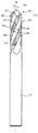
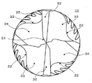
以下、本発明の一実施形態に係る回転工具を図面に基づいて説明する。図1、図2は、本発明の一実施形態に係る回転工具10を示す正面図、側面図であり、図3は、回転工具10を先端側から見て示す図である。図1〜図3に示すように、回転工具10は、全体として回転軸Rを軸心とする長尺な円柱状に形成されている。回転工具10は、後端側(図1及び図2中、下側)が円柱状のままシャンク部12として形成され、先端側(図1及び図2中、上側)が加工部14として形成されている。
Hereinafter, a rotary tool according to an embodiment of the present invention will be described with reference to the drawings. 1 and 2 are a front view and a side view showing a
シャンク部12は、マシニングセンター、フライス盤、または電動工具などの図示しない駆動源により回転駆動されるスピンドルに把持される。これにより、回転工具10は、スピンドルと一体に回転軸R回りに回転し、加工部14が被加工物と接触することにより被加工物を加工する。回転工具10が取り付けられるスピンドル等は、公知の構成を採用することができ、如何なるものを用いてもよい。
The
加工部14は、シャンク部12の先端側に連続して形成され、被加工物を加工する刃が形成されている。本実施形態では、回転工具10は、右ねじれ左回転の工具として形成されている。ただし、回転工具10は、左ねじれ右回転の工具として形成されてもよい。加工部14は、回転工具10の側面に形成されたエンドミル部20と、回転工具10の先端に形成されたドリル部30と、が連続して形成されている。
The
エンドミル部20は、シャンク部12の先端側およびドリル部30の後端側に連続して形成されている。エンドミル部20には、螺旋状に4つの切刃(外周刃)26が形成されるように、4本の螺旋溝22が形成されている。言い換えれば、エンドミル部20には、4本の螺旋溝22が形成され、この4本の螺旋溝22に挟まれた4つの側面部(螺旋溝22が形成されていない領域)24には、螺旋溝22との一方の縁(図1及び図2中、右側の縁)に切刃26が形成されている。図4は、図1中A−A方向から見たAA視図である。なお、図4中、回転工具10の断面にはハッチングを付している。図4に示すように、本実施形態では、4つの螺旋溝22は、回転工具10の周方向に沿って均等な間隔で形成されている。ただし、螺旋溝22は、周方向に均等な間隔で形成されるものに限定されず、交互に異なる大きさでもよく、それぞれに異なる大きさでもよい。
The
螺旋溝22に挟まれた側面部24のそれぞれは、切刃26を含めて凹凸状(凹凸25)に形成されている。この凹凸25は、回転軸Rに対して垂直な波面である波形に形成されている。言い換えれば、凹凸25は、波の進行方向が回転軸Rに沿った波形状に形成されている。このように側面部24及び切刃26に凹凸25が形成されることにより、エンドミル部20の加工能力を向上させることができる。
Each of the
ドリル部30は、エンドミル部20の先端に連続して形成されている。ドリル部30は、先端が尖った形状に形成されている。ドリル部30の先端角度Aは、ドリル部30によってワークを穿孔加工するときに、ワーク等からドリル部30にかかる力が、回転軸R方向と、回転軸R方向に対して垂直な方向とにおいて、略等しくなる角度とすることが好ましい。具体的には、ドリル部30の先端角度は、好ましくは105°〜135°、更に好ましくは105°〜120°、更に好ましくは118°である。本実施形態では、ドリル部30の先端角度Aは約105°である。
The
ドリル部30には、エンドミル部20の切刃26に連続して、穿孔加工のためのシンニング(底刃)32が形成されている。図3に示すように、シンニング32は、エンドミル部20の4つの切刃26のうち1つ置きである2つの切刃26に連続して、2つ形成されている。つまり、シンニング32は、180度毎に形成されている。シンニング32は、図3に示すようにX形のシンニング面とするのが好ましいが、S形、XS形、ノッチ形など、X形以外の形状としてもよい。シンニング32の回転方向後ろ側(図3中、時計回り側)には、逃げ面33が形成されている。
In the
エンドミル部20の残りの切刃26の先端側は、穿孔加工に伴う切屑を排出するための傾斜部(切屑排出部)34が形成される。つまり、ドリル部30には、エンドミル部20の4つの切刃26のうち1つ置きの先端側に連続してシンニング32が形成され、残りの先端側に連続して切屑排出部34が形成されている。ここで、切屑排出部34は、隣接するシンニング32のすくい面に連続し、シンニング32のエッジが際立ち、且つ、シンニング32により削られた切屑がエンドミル部30側(図1中、下側)に好適に排出されるように、傾斜状に切り欠かれて形成される。切屑排出部34の後端側(図1中、下側)は、エンドミル部30の切刃26及び螺旋溝22に連続する。
On the tip end side of the remaining
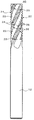
本実施形態にかかる回転工具10を製造する場合には、一例として、まず、図5に示すような部材40を用意する。なお、図5では、図1〜図4と同一の構成部位には、同一の符号を付している。図5に示すように、部材40は、エンドミル部20が先端側(図5中、上側)まで連続して形成されている。部材40としては、例えば側面に4つの切刃が形成された公知のエンドミルを用いることができる。なお、部材40は、先端までエンドミル部20(切刃26)が形成されている必要はなく、例えばドリル部30となる先端部は切刃26などが形成されることなく円柱状であってもよい。
When manufacturing the
そして、用意した部材40に対して、先端側を加工し、105°〜135°の先端角度にするとともに、4つの切刃26のうち、1つ置きの先端側の切刃26に連続してシンニング32を形成し、残りの先端側の切刃26に連続して切屑排出部34を形成する。このときには、シンニング32を180度ごとに形成すればよいので、シンニング研磨を容易に施すことができ、切刃26に連続したシンニング32を高精度に形成することができる。また、残りの切刃(シンニング32が連続しない切刃)26は、穿孔加工において切屑(切粉)が好適に排除されるように、切刃26の先端側を削って切屑排出部(ポケット)34を形成する。このように部材40を用意して回転工具10を形成することにより、本実施形態にかかる回転工具10を容易に製造することができる。こうした回転工具10の製造方法は、回転工具10の先端が摩耗などで傷んだ場合にも適用することができ、切刃26の長さの限りでシンニング32と切屑排出部34を再研磨して、回転工具10を利用することができる。
And the front end side is processed with respect to the
ここで、本実施形態の回転工具10との比較例として、エンドミルの先端が丸められたラジアスエンドミルは、回転軸に対してある程度傾斜(例えば、40度など)させて移動させることによって穿孔加工をすることもできる。しかし、ラジアスエンドミルは、回転軸方向に沿って穿孔加工をすることはできず、加工対象が限定される。これに対して、本実施形態の回転工具10は、シンニング32が形成されたドリル部30を有するので、回転軸R方向に沿った穿孔加工が可能であり、さまざまな加工対象(ワーク)に穿孔加工および拡孔加工を施すことができる。そして、シンニング32が形成されたドリル部30は、ラジアスエンドミルの先端部とはまったく異なる形状であり、先端の刃の耐久性がラジアスエンドミルに比して著しく向上している。なお、本実施形態の回転工具10は、厚さが回転工具直径以下であるワークに用いられることが好ましい。
Here, as a comparative example with the
また、一般に、ドリルは、底刃の数が多いほど、心厚を大きくして剛性を高めることができるが、切屑を排出する刃間の溝が小さくなって穿孔加工中に切屑が詰まりやすくなる。これに対して、本実施形態の回転工具10は、ドリル部30に2つのシンニング32と切屑排出部34(ポケット)とが形成されているので、高い穿孔加工能力を実現することができる。
In general, as the number of bottom blades increases, the thickness of the drill can be increased by increasing the thickness of the core, but the groove between the blades for discharging the chips becomes smaller and the chips are more easily clogged during drilling. . On the other hand, since the two
以上説明した本実施形態の回転工具10は、ドリル部30の先端角が約105°に形成され、エンドミル部20の側面に4つの螺旋溝22が形成されて4つの切刃26が形成されている。そして、4つの切刃26の1つ置きの先端側に連続してシンニング32が形成され、残余の切刃26の先端側に連続して切屑排出部34が形成されている。これにより、単一の回転工具10を用いて、ドリル部30によって穿孔加工を行うことができるとともに、エンドミル部20によって拡孔加工を行うことができる。また、ドリル部30には、切刃26の1つ置きにシンニング32と切屑排出部34とが形成されているので、加工に伴う切屑の排出を好適に行って効率よく穿孔加工を行うことができる。そして、エンドミル部20には、4つの切刃26が形成されているので、高い加工能力で拡孔加工を行うことができる。
In the
また、本実施形態の回転工具10は、ドリル部30が2つのシンニング32を有する2枚刃に形成されているので、シンニング32を形成するためのシンニング研磨を容易に高精度に行うことができる。ドリル部30にシンニング32を形成することにより、回転工具10を用いた加工時のスラスト値を低下させて先端の摩耗及びチッピングを軽減することができ、回転工具10の耐久性を向上させることができる。しかも、本実施形態の回転工具10は、4つの螺旋溝22が形成されて4つの切刃26が形成れた部材40を用意し、この部材40の先端を尖った形状にするとともに、1つ置きの切刃の先端側に連続してシンニング32を形成し、残余の切刃の先端側に連続して切屑排出部34を形成することにより、容易に製造することができる。
Further, in the
上記の実施形態では、回転工具10の側面部24には、回転軸Rに対して垂直な波面の凹凸25が形成されるものとしたが、回転軸Rに対して傾斜した波面の凹凸が形成されてもよい。また、波形については、正弦波状としてもよく、矩形波状、又は、三角波状などの凹凸形状に形成してもよい。また、側面部24の一部だけが凹凸状に形成されてもよいし、側面部24及び切刃26が凹凸状でなくてもよい。
In the above embodiment, the
以上、本発明の実施の形態について説明してきたが、上記した発明の実施の形態は、本発明の理解を容易にするためのものであり、本発明を限定するものではない。本発明は、その趣旨を逸脱することなく、変更、改良され得るとともに、本発明にはその均等物が含まれることはもちろんである。また、上述した課題の少なくとも一部を解決できる範囲、または、効果の少なくとも一部を奏する範囲において、実施形態および変形例の任意の組み合わせが可能であり、特許請求の範囲および明細書に記載された各構成要素の任意の組み合わせ、または、省略が可能である。 Although the embodiments of the present invention have been described above, the above-described embodiments of the present invention are for facilitating the understanding of the present invention and are not intended to limit the present invention. The present invention can be changed and improved without departing from the gist thereof, and the present invention includes the equivalents thereof. In addition, any combination of the embodiment and the modified example is possible within a range where at least a part of the above-described problems can be solved or a range where at least a part of the effect can be achieved, and is described in the claims and the specification. Any combination or omission of each component is possible.
10 回転工具
12 シャンク部
14 加工部
20 エンドミル部
22 螺旋溝
24 側面部
25 凹凸
26 切刃
30 ドリル部
32 シンニング
34 切屑排出部
40 部材
DESCRIPTION OF
Claims (3)
先端角が105°〜135°であり、
側面に4つの螺旋溝が形成されており、
前記4つの螺旋溝に挟まれた4つの側面部のそれぞれには、一方の縁に切刃が形成されており、
前記4つの側面部に形成された切刃には、1つ置きの切刃の先端側に連続してシンニングが形成され、残余の切刃の先端側に連続して切屑排出部が形成されている、
回転工具。 A rotary tool that rotates around a rotation axis to process a workpiece,
The tip angle is 105 ° to 135 °,
Four spiral grooves are formed on the side,
A cutting blade is formed on one edge of each of the four side surfaces sandwiched between the four spiral grooves,
The cutting blades formed on the four side surfaces are formed with thinning continuously on the tip side of every other cutting blade, and a chip discharge portion is formed continuously on the tip side of the remaining cutting blades. Yes,
Rotary tool.
前記側面部は、前記回転軸に対して垂直な波面の凹凸状に形成されている、
回転工具。 The rotary tool according to claim 1,
The side surface portion is formed in an uneven shape of a wavefront perpendicular to the rotation axis.
Rotary tool.
全体として円柱であり、側面に4つの螺旋溝が形成され、前記4つの螺旋溝に挟まれた4つの側面部のそれぞれには一方の縁に切刃が形成された部材を用意する工程と、
前記用意した部材を105°〜135°の先端角にするとともに、前記4つの側面部に形成された切刃のうち1つ置きの切刃の先端側に連続してシンニングを形成し、残余の切刃の先端側に連続して切屑排出部を形成する工程と、
を含む回転工具の製造方法。 A method for producing the rotary tool according to claim 1,
A step of preparing a member that is a cylinder as a whole, has four spiral grooves formed on a side surface, and each of four side surfaces sandwiched between the four spiral grooves has a cutting edge on one edge;
The prepared member has a tip angle of 105 ° to 135 °, and a thinning is continuously formed on the tip side of every other cutting blade among the four cutting blades formed on the four side surfaces, Forming a chip discharge part continuously on the tip side of the cutting blade; and
The manufacturing method of the rotary tool containing this.
Priority Applications (1)
| Application Number | Priority Date | Filing Date | Title |
|---|---|---|---|
| JP2015032730A JP2016155178A (en) | 2015-02-23 | 2015-02-23 | Rotary tool and manufacturing method thereof |
Applications Claiming Priority (1)
| Application Number | Priority Date | Filing Date | Title |
|---|---|---|---|
| JP2015032730A JP2016155178A (en) | 2015-02-23 | 2015-02-23 | Rotary tool and manufacturing method thereof |
Publications (1)
| Publication Number | Publication Date |
|---|---|
| JP2016155178A true JP2016155178A (en) | 2016-09-01 |
Family
ID=56824560
Family Applications (1)
| Application Number | Title | Priority Date | Filing Date |
|---|---|---|---|
| JP2015032730A Pending JP2016155178A (en) | 2015-02-23 | 2015-02-23 | Rotary tool and manufacturing method thereof |
Country Status (1)
| Country | Link |
|---|---|
| JP (1) | JP2016155178A (en) |
Cited By (2)
| Publication number | Priority date | Publication date | Assignee | Title |
|---|---|---|---|---|
| CN106624079A (en) * | 2016-12-09 | 2017-05-10 | 海南中智康弘精工技术有限公司 | Spiral corrugated blade type drilling and milling integrated cutter |
| JPWO2021229854A1 (en) * | 2020-05-14 | 2021-11-18 |
Citations (15)
| Publication number | Priority date | Publication date | Assignee | Title |
|---|---|---|---|---|
| GB1341453A (en) * | 1971-10-20 | 1973-12-19 | Diagrit Grinding Co Ltd | Drill |
| JPS57202615U (en) * | 1981-01-06 | 1982-12-23 | ||
| JPS60141415A (en) * | 1983-12-28 | 1985-07-26 | Toshiba Tungaloy Co Ltd | Small diameter drill |
| JPS6274917U (en) * | 1985-10-28 | 1987-05-13 | ||
| US5173014A (en) * | 1992-02-07 | 1992-12-22 | General Motors Corporation | Four flute center cutting drill |
| US5273380A (en) * | 1992-07-31 | 1993-12-28 | Musacchia James E | Drill bit point |
| JPH0615922U (en) * | 1992-08-05 | 1994-03-01 | 修 藤城 | End mill |
| JPH0740117A (en) * | 1993-07-27 | 1995-02-10 | Mitsubishi Materials Corp | Drilling tool |
| US20010031180A1 (en) * | 1999-12-10 | 2001-10-18 | Vasudeva Kailash C. | Drill bit for non-linear drilling |
| WO2004082874A1 (en) * | 2003-03-21 | 2004-09-30 | Gühring, Jörg | Sandwich drill |
| JP2005052939A (en) * | 2003-08-05 | 2005-03-03 | Hitachi Tool Engineering Ltd | Deburring drill |
| JP2006263912A (en) * | 2005-03-24 | 2006-10-05 | Emuge-Werk Richard Glimpel Gmbh & Co Kg | Drill thread milling cutter |
| JP2007030491A (en) * | 2005-07-27 | 2007-02-08 | Mejiro:Kk | Small hole drill for bamboo cane |
| JP2009039811A (en) * | 2007-08-08 | 2009-02-26 | Kumamoto Univ | Drilling tools and drilling methods for fiber reinforced composites |
| WO2014073610A1 (en) * | 2012-11-09 | 2014-05-15 | 株式会社ミヤギタノイ | Drill and bore formation method |
-
2015
- 2015-02-23 JP JP2015032730A patent/JP2016155178A/en active Pending
Patent Citations (15)
| Publication number | Priority date | Publication date | Assignee | Title |
|---|---|---|---|---|
| GB1341453A (en) * | 1971-10-20 | 1973-12-19 | Diagrit Grinding Co Ltd | Drill |
| JPS57202615U (en) * | 1981-01-06 | 1982-12-23 | ||
| JPS60141415A (en) * | 1983-12-28 | 1985-07-26 | Toshiba Tungaloy Co Ltd | Small diameter drill |
| JPS6274917U (en) * | 1985-10-28 | 1987-05-13 | ||
| US5173014A (en) * | 1992-02-07 | 1992-12-22 | General Motors Corporation | Four flute center cutting drill |
| US5273380A (en) * | 1992-07-31 | 1993-12-28 | Musacchia James E | Drill bit point |
| JPH0615922U (en) * | 1992-08-05 | 1994-03-01 | 修 藤城 | End mill |
| JPH0740117A (en) * | 1993-07-27 | 1995-02-10 | Mitsubishi Materials Corp | Drilling tool |
| US20010031180A1 (en) * | 1999-12-10 | 2001-10-18 | Vasudeva Kailash C. | Drill bit for non-linear drilling |
| WO2004082874A1 (en) * | 2003-03-21 | 2004-09-30 | Gühring, Jörg | Sandwich drill |
| JP2005052939A (en) * | 2003-08-05 | 2005-03-03 | Hitachi Tool Engineering Ltd | Deburring drill |
| JP2006263912A (en) * | 2005-03-24 | 2006-10-05 | Emuge-Werk Richard Glimpel Gmbh & Co Kg | Drill thread milling cutter |
| JP2007030491A (en) * | 2005-07-27 | 2007-02-08 | Mejiro:Kk | Small hole drill for bamboo cane |
| JP2009039811A (en) * | 2007-08-08 | 2009-02-26 | Kumamoto Univ | Drilling tools and drilling methods for fiber reinforced composites |
| WO2014073610A1 (en) * | 2012-11-09 | 2014-05-15 | 株式会社ミヤギタノイ | Drill and bore formation method |
Cited By (4)
| Publication number | Priority date | Publication date | Assignee | Title |
|---|---|---|---|---|
| CN106624079A (en) * | 2016-12-09 | 2017-05-10 | 海南中智康弘精工技术有限公司 | Spiral corrugated blade type drilling and milling integrated cutter |
| JPWO2021229854A1 (en) * | 2020-05-14 | 2021-11-18 | ||
| WO2021229854A1 (en) * | 2020-05-14 | 2021-11-18 | 株式会社ビック・ツール | Hollow drill for medical use |
| JP7555139B2 (en) | 2020-05-14 | 2024-09-24 | 株式会社ビック・ツール | Medical Hollow Drill |
Similar Documents
| Publication | Publication Date | Title |
|---|---|---|
| US9878379B2 (en) | Cutting tool with enhanced chip evacuation capability and method of making same | |
| JP5474032B2 (en) | Rotary cutting tool | |
| US8690493B2 (en) | End mill | |
| JP5877789B2 (en) | drill | |
| US10010332B2 (en) | Cutting tool and corresponding assembly | |
| KR101236041B1 (en) | Throw-away cutting rotary tool | |
| JP2011206863A (en) | End mill | |
| CN104837585A (en) | Face cutter for machining fibre-reinforced materials such as carbon-fibre-reinforced plastics (cfrp) | |
| CN107107212A (en) | Formed end mill | |
| JP2010234462A (en) | End mill | |
| KR101667010B1 (en) | a end mill for complex machining | |
| CN105750596B (en) | drill bit | |
| JPWO2018092351A1 (en) | Cutting tool and cutting method | |
| JP2004276142A (en) | End mill | |
| JP2018126832A (en) | Taper ball end mill | |
| CN204818201U (en) | combination tool | |
| JP5895654B2 (en) | End mill | |
| JP2007245338A (en) | Milling cutter | |
| US20200269333A1 (en) | Form cutting method | |
| US7337523B1 (en) | Methods and apparatus for an annular core cutter | |
| JP4666282B2 (en) | Drill | |
| JPH0819911A (en) | Drill | |
| JP2000176738A (en) | Cutting tools | |
| CN209886764U (en) | Hybrid spiral angle milling cutter | |
| JP5259751B2 (en) | Reamer |
Legal Events
| Date | Code | Title | Description |
|---|---|---|---|
| A02 | Decision of refusal |
Free format text: JAPANESE INTERMEDIATE CODE: A02 Effective date: 20160815 |