JP2016190821A - Mint refinery apparatus and system - Google Patents
Mint refinery apparatus and system Download PDFInfo
- Publication number
- JP2016190821A JP2016190821A JP2015072534A JP2015072534A JP2016190821A JP 2016190821 A JP2016190821 A JP 2016190821A JP 2015072534 A JP2015072534 A JP 2015072534A JP 2015072534 A JP2015072534 A JP 2015072534A JP 2016190821 A JP2016190821 A JP 2016190821A
- Authority
- JP
- Japan
- Prior art keywords
- mint
- heater
- temperature
- crystal
- refrigerator
- Prior art date
- Legal status (The legal status is an assumption and is not a legal conclusion. Google has not performed a legal analysis and makes no representation as to the accuracy of the status listed.)
- Granted
Links
- 235000006679 Mentha X verticillata Nutrition 0.000 title claims abstract description 79
- 235000002899 Mentha suaveolens Nutrition 0.000 title claims abstract description 79
- 235000001636 Mentha x rotundifolia Nutrition 0.000 title claims abstract description 79
- 238000001816 cooling Methods 0.000 claims abstract description 45
- NOOLISFMXDJSKH-KXUCPTDWSA-N (-)-Menthol Chemical compound CC(C)[C@@H]1CC[C@@H](C)C[C@H]1O NOOLISFMXDJSKH-KXUCPTDWSA-N 0.000 claims abstract description 31
- 239000013078 crystal Substances 0.000 claims description 58
- NOOLISFMXDJSKH-UHFFFAOYSA-N DL-menthol Natural products CC(C)C1CCC(C)CC1O NOOLISFMXDJSKH-UHFFFAOYSA-N 0.000 claims description 25
- 238000007670 refining Methods 0.000 claims description 21
- 238000000746 purification Methods 0.000 claims description 19
- 239000012267 brine Substances 0.000 claims description 11
- HPALAKNZSZLMCH-UHFFFAOYSA-M sodium;chloride;hydrate Chemical compound O.[Na+].[Cl-] HPALAKNZSZLMCH-UHFFFAOYSA-M 0.000 claims description 11
- XLYOFNOQVPJJNP-UHFFFAOYSA-N water Substances O XLYOFNOQVPJJNP-UHFFFAOYSA-N 0.000 claims description 10
- 239000007788 liquid Substances 0.000 claims description 9
- 238000007711 solidification Methods 0.000 claims description 2
- 230000008023 solidification Effects 0.000 claims description 2
- 238000002425 crystallisation Methods 0.000 abstract description 13
- 230000008025 crystallization Effects 0.000 abstract description 13
- 230000015572 biosynthetic process Effects 0.000 abstract description 2
- 230000008859 change Effects 0.000 description 19
- 229940041616 menthol Drugs 0.000 description 13
- CURLTUGMZLYLDI-UHFFFAOYSA-N Carbon dioxide Chemical compound O=C=O CURLTUGMZLYLDI-UHFFFAOYSA-N 0.000 description 8
- 238000009529 body temperature measurement Methods 0.000 description 7
- 238000000034 method Methods 0.000 description 6
- 230000000052 comparative effect Effects 0.000 description 5
- 238000012546 transfer Methods 0.000 description 5
- 229910002092 carbon dioxide Inorganic materials 0.000 description 4
- 239000001569 carbon dioxide Substances 0.000 description 4
- 239000000498 cooling water Substances 0.000 description 4
- 238000010586 diagram Methods 0.000 description 4
- 238000009826 distribution Methods 0.000 description 4
- 239000012535 impurity Substances 0.000 description 4
- 230000001965 increasing effect Effects 0.000 description 4
- 239000000463 material Substances 0.000 description 4
- 230000008569 process Effects 0.000 description 4
- 239000003507 refrigerant Substances 0.000 description 4
- 239000007787 solid Substances 0.000 description 4
- 229910001220 stainless steel Inorganic materials 0.000 description 4
- 239000010935 stainless steel Substances 0.000 description 4
- 238000000605 extraction Methods 0.000 description 3
- 239000002184 metal Substances 0.000 description 3
- 229910052751 metal Inorganic materials 0.000 description 3
- 239000004570 mortar (masonry) Substances 0.000 description 3
- 239000000523 sample Substances 0.000 description 3
- 238000003756 stirring Methods 0.000 description 3
- 239000000725 suspension Substances 0.000 description 3
- 239000002826 coolant Substances 0.000 description 2
- 230000007423 decrease Effects 0.000 description 2
- 230000003028 elevating effect Effects 0.000 description 2
- 238000010438 heat treatment Methods 0.000 description 2
- 238000012423 maintenance Methods 0.000 description 2
- 238000004519 manufacturing process Methods 0.000 description 2
- 230000007246 mechanism Effects 0.000 description 2
- 238000002156 mixing Methods 0.000 description 2
- 239000000203 mixture Substances 0.000 description 2
- 238000012545 processing Methods 0.000 description 2
- 230000005855 radiation Effects 0.000 description 2
- 229920002050 silicone resin Polymers 0.000 description 2
- 238000001256 steam distillation Methods 0.000 description 2
- 229910001006 Constantan Inorganic materials 0.000 description 1
- RYGMFSIKBFXOCR-UHFFFAOYSA-N Copper Chemical compound [Cu] RYGMFSIKBFXOCR-UHFFFAOYSA-N 0.000 description 1
- 229910000831 Steel Inorganic materials 0.000 description 1
- 230000002528 anti-freeze Effects 0.000 description 1
- 238000009835 boiling Methods 0.000 description 1
- 239000000919 ceramic Substances 0.000 description 1
- 238000004140 cleaning Methods 0.000 description 1
- 229910052802 copper Inorganic materials 0.000 description 1
- 239000010949 copper Substances 0.000 description 1
- 230000003247 decreasing effect Effects 0.000 description 1
- 239000003814 drug Substances 0.000 description 1
- 229940079593 drug Drugs 0.000 description 1
- 238000001704 evaporation Methods 0.000 description 1
- 239000000796 flavoring agent Substances 0.000 description 1
- 235000019634 flavors Nutrition 0.000 description 1
- 235000013373 food additive Nutrition 0.000 description 1
- 239000002778 food additive Substances 0.000 description 1
- 239000003205 fragrance Substances 0.000 description 1
- 238000007710 freezing Methods 0.000 description 1
- 230000008014 freezing Effects 0.000 description 1
- 230000001771 impaired effect Effects 0.000 description 1
- 238000009413 insulation Methods 0.000 description 1
- JEIPFZHSYJVQDO-UHFFFAOYSA-N iron(III) oxide Inorganic materials O=[Fe]O[Fe]=O JEIPFZHSYJVQDO-UHFFFAOYSA-N 0.000 description 1
- 230000007257 malfunction Effects 0.000 description 1
- 230000004048 modification Effects 0.000 description 1
- 238000012986 modification Methods 0.000 description 1
- 229910001120 nichrome Inorganic materials 0.000 description 1
- 239000002244 precipitate Substances 0.000 description 1
- 238000002360 preparation method Methods 0.000 description 1
- 238000003825 pressing Methods 0.000 description 1
- 230000002250 progressing effect Effects 0.000 description 1
- 230000008439 repair process Effects 0.000 description 1
- 229920005989 resin Polymers 0.000 description 1
- 239000011347 resin Substances 0.000 description 1
- 229910000679 solder Inorganic materials 0.000 description 1
- 239000000243 solution Substances 0.000 description 1
- 239000010959 steel Substances 0.000 description 1
- 238000003860 storage Methods 0.000 description 1
- 239000000126 substance Substances 0.000 description 1
- 230000003313 weakening effect Effects 0.000 description 1
Images
Landscapes
- Organic Low-Molecular-Weight Compounds And Preparation Thereof (AREA)
Abstract
Description
本発明は、天然l(エル)−メントール(ミント)を生成するための装置に関する。さらに詳しくは、粗製ハッカ油からミントを晶析するためのミント精製装置に関する。 The present invention relates to an apparatus for producing natural l-menthol (mint). More specifically, the present invention relates to a mint refining apparatus for crystallizing mint from crude mint oil.
天然l(エル)−メントールは、例えば食品添加物、香料、医薬などの分野で広く用いられる物質である。ハッカの葉から水蒸気蒸留などの処理で得られた粗製ハッカ油の主成分で、これを冷却して析出する固形物である。
メントールを晶析あるいは精製するための装置として、以下の特許文献1、2、3の装置などが知られている。
Natural l-menthol is a substance widely used in the fields of food additives, fragrances, medicines and the like. It is a main component of crude mint oil obtained from mint leaves by a process such as steam distillation, and is a solid that precipitates upon cooling.
As apparatuses for crystallizing or refining menthol, apparatuses of the following
特許文献1には、粗製ハッカ油からl−メントールを精製する装置が開示されている。その晶析装置は、粗製ハッカ油が投入されるチャンバを備えている。そのチャンバ内には、l−メントールを晶析させるための複数のプレートが並べられている。そのプレートおよびチャンバには、加熱ユニットおよび冷却ユニットを通じて熱媒体を循環させる導管が連結され、それぞれ温度が制御されている。
このメントール精製装置では、手間の掛からない1サイクル精製のため、まず0〜20℃のどこかの温度点に精密制御した冷却面で急冷して高純度の種結晶を得て、種結晶を起点に、25〜45℃の間のどこかの温度点から、24時間毎に0.1〜10℃の低下速度で、100〜140時間かけて緩やかに低下するようにチャンバを冷却して、前記プレート上にl−メントールの結晶を晶析させる、というものである。
In this menthol refining device, for one-cycle refining without hassle, first of all, a high-purity seed crystal is obtained by rapid cooling on a cooling surface precisely controlled at a temperature point of 0 to 20 ° C. In addition, the chamber is cooled from a temperature point between 25 to 45 ° C. at a rate of 0.1 to 10 ° C. every 24 hours so as to gradually decrease over 100 to 140 hours, Crystals of l-menthol are crystallized on the plate.
特許文献2には、強制循環型晶析装置が開示されている。このものは、溶液内の種結晶あるいは小径の結晶粒をチャンバ内で下から上に対流させながら種結晶上に結晶を成長させ、成長した結晶をチャンバの下方から抜き取るというものである。前記循環は、チャンバの上方に設けられた静穏域から懸濁液を抜取り、その懸濁液から水分を蒸発させ濃度を調整した後に、チャンバの下方から再供給することにより、生じている。
特許文献3には、原料粗メントールと水の混合物に超臨界状態の二酸化炭素を加えて、メントールを抽出する装置およびその方法が記載されている。それによれば、まず原料粗メントールと水の混合物を抽出槽に入れて、その中に温度・圧力の条件を異にした超臨界状態の二酸化炭素を順次混合する。一回目の混合で不純物等を二酸化炭素に溶解させて除去し、二回目の混合で二酸化炭素に溶解させてメントールを抽出し、高沸点樹脂などの抽出残渣を分離除去する。
粗製ハッカ油などからミントなどのl−メントールを晶析して精製するには、一般的に結晶を緩やかに成長させるのがよいとされている。緩やかに成長させると成長していくメントール結晶が密にきめ細かく積み重なるので、不純物が混入しにくく風味が損なわれることがない。結晶の成長過程で部分的温度ムラなどがあると、不純物がメントール結晶内
に混入結晶しやすくなる。そのためには、粗製ハッカ油の温度を晶析に必要な温度まで緩やかに、かつ、ムラなく下げることが好ましい。晶析温度にムラがあると、結晶成長にムラが生じ、不純物がメントール結晶内に混入結晶しやすくメントール結晶の品質が低下するからである。
例えば、晶析装置のタンクに入れられた粗製ハッカ油を前記タンクの底付近から冷やして、次第に上方に向かって晶析させることにより、抽出残渣を上方に絞り出すように晶析することができる。そのような晶析装置の場合には、タンクの上方において半径方向に温度ムラが生じやすい。
また、このような晶析装置に用いる冷却庫は高さが800mm〜1500mmである。粗製ハッカ油を入れた結晶缶を冷却庫に底を下に開放された液面を上に向けて、作業者が設置しやすく取り出しやすい冷却庫高さである。また、その蓋は、ヒンジなどで連結されており、冷却庫のヒンジ側では蓋を開いたときでも蓋が接近しておりアクセスが悪く、仕込みや結晶した1−メントールの取出しなどの作業性が低い。
In order to crystallize and refine l-menthol such as mint from crude mint oil or the like, it is generally said that it is better to grow crystals slowly. When grown slowly, the growing menthol crystals are densely and finely stacked, so that impurities are hardly mixed and the flavor is not impaired. If there is a partial temperature unevenness in the crystal growth process, impurities tend to be mixed into the menthol crystal. For this purpose, it is preferable that the temperature of the crude mint oil is gradually and evenly lowered to the temperature necessary for crystallization. This is because, if the crystallization temperature is uneven, crystal growth is uneven, and impurities are likely to be mixed into the menthol crystal and the quality of the menthol crystal is lowered.
For example, by cooling the crude mint oil contained in the tank of the crystallizer from the vicinity of the bottom of the tank and gradually crystallizing it upward, the extraction residue can be crystallized to squeeze upward. In the case of such a crystallizer, temperature unevenness tends to occur in the radial direction above the tank.
Moreover, the refrigerator used for such a crystallizer has a height of 800 mm to 1500 mm. The crystal can containing crude mint oil is placed in a refrigerator with the liquid level open at the bottom and facing up so that the operator can easily install and take out the refrigerator. In addition, the lid is connected by a hinge, etc., and even when the lid is opened on the hinge side of the refrigerator, the lid is close and inaccessible, and workability such as preparation and removal of crystallized 1-menthol is improved. Low.
そこで、本発明は純度の高いメントールの結晶生成率が高く、かつ、作業性の高い、ミント精製装置およびミント精製システムを提供することを課題とする。 Then, this invention makes it a subject to provide the mint refinement | purification apparatus and mint refinement | purification system with the high crystal production rate of a highly purified menthol and high workability | operativity.
(1)本発明のミント精製装置は、結晶缶に入れられた粗製ハッカ油を放冷または冷却して、l−メントールを晶析させるミント精製装置であって、前記結晶缶を収容し、底板の下面にブライン又は冷水を流通する冷却管を底板に伝熱可能に配置する冷却庫と、その冷却庫の上部の開口を塞ぐ蓋体とからなり、その蓋体の前記冷却庫に面する裏面に、ヒータと、そのヒータの熱が伝導する伝導板と、その伝導板の下方に配置されるファンとが設けられていることを特徴とする。
また、粗製ハッカ油とは、植物由来であって、ハッカの葉などから水蒸気蒸留して得られるようなハッカ油であり、30重量%〜95重量%のl(エル)−メントールを含む。
また、精製されたl−メントールは、少なくとも99重量%の純度を有するものである。
(1) A mint refining device of the present invention is a mint refining device that cools or cools crude mint oil contained in a crystal can to crystallize l-menthol, which contains the crystal can, and has a bottom plate The cooling pipe which distributes brine or cold water to the bottom of the bottom plate so that heat can be transferred to the bottom plate, and the lid that closes the opening at the top of the cooling box, the back surface of the lid facing the cooling box Further, a heater, a conductive plate that conducts heat of the heater, and a fan disposed below the conductive plate are provided.
Crude mint oil is mint oil that is derived from plants and obtained by steam distillation from mint leaves and the like, and contains 30% to 95% by weight of l-menthol.
The purified l-menthol has a purity of at least 99% by weight.
(2)前記冷却庫の上部の開口周囲を冷却するブライン又は冷水を流通する上部冷却管が、前記冷却庫側板の上方を囲繞するように配置されているのが好ましい。
(3)このようなヒータが棒状であり、前記伝導板の断面形状が波形状であり、その伝導板の上方から見た波形状の溝内に前記ヒータが配置され前記冷却庫側から隠蔽されているものが好ましい。
(2) It is preferable that the upper cooling pipe which distribute | circulates the brine or cold water which cools the opening periphery of the upper part of the said refrigerator is arrange | positioned so that the upper part of the said refrigerator side plate may be surrounded.
(3) Such a heater is rod-shaped, and the cross-sectional shape of the conductive plate is corrugated, and the heater is arranged in a wave-shaped groove as viewed from above the conductive plate and is concealed from the refrigerator side. Are preferred.
(4)さらに、前記伝導板に略同形状の第2の伝導板を上方に重ねて前記ヒータを挟持しているものが好ましい。 (4) Further, it is preferable that a second conductive plate having substantially the same shape is superimposed on the conductive plate so as to sandwich the heater.
(5)前記蓋体を昇降する昇降装置をさらに備えているものが好ましい。 (5) What further has the raising / lowering apparatus which raises / lowers the said cover body is preferable.
(6)本発明のミント精製システムは、上述のミント精製装置と、前記蓋体の下方でハッカ油液面より上の空間温度を含む温度情報を検知する温度センサと、その温度センサから得られた温度情報に基づいて、ヒータの温度を制御して、結晶缶の底部と結晶缶の液面との温度差を設定制御しながら、結晶缶に入れられたハッカ油が缶底側から所望の冷却速度(凝固速度)になるように前記ヒータを制御する制御部とを備えていることを特徴とする。 (6) The mint refining system of the present invention is obtained from the above-described mint refining device, a temperature sensor for detecting temperature information including a space temperature above the mint oil liquid level below the lid, and the temperature sensor. Based on the temperature information, the temperature of the heater is controlled to set and control the temperature difference between the bottom of the crystal can and the liquid level of the crystal can, while the mint oil contained in the crystal can is desired from the bottom of the can. And a control unit that controls the heater so as to have a cooling rate (solidification rate).
ここで「温度情報」とは、温度センサの検出値、その検出値から換算される値を含む。
さらに「所望の冷却」とは、所定の冷却時間における結晶缶の高さ方向の温度分布状態を含み、所定時における冷却管の冷却の具合を示すものである。
Here, “temperature information” includes a detected value of the temperature sensor and a value converted from the detected value.
Furthermore, “desired cooling” includes the temperature distribution state in the height direction of the crystal can during a predetermined cooling time, and indicates the degree of cooling of the cooling pipe at a predetermined time.
(1)本発明のミント精製装置では、伝導板を通じてヒータの熱が均一に蓋体の裏面に拡がると共に、その加熱された板からの輻射熱および板に接触する空気のファンによる循環により、ミント精製装置内の上部の温度が不均一になるのを防止することができ、結晶の純度や結晶の生成効率を高めることができる。 (1) In the mint refining apparatus of the present invention, the heat of the heater is uniformly spread to the back surface of the lid through the conductive plate, and the mint refining is performed by the radiant heat from the heated plate and the circulation of the air contacting the plate by the fan It is possible to prevent the temperature of the upper part in the apparatus from becoming non-uniform, and it is possible to increase crystal purity and crystal generation efficiency.
(2)このような装置において、前記冷却庫の上部の開口周囲を冷却するブライン又は冷水を流通する上部冷却管が、前記冷却庫側板の上方を囲繞するように配置されている場合は、冷却庫の底面に冷却管が密に並び、冷却庫の側壁上方にも上部冷却管が囲んでいるので、メントール結晶に必要な冷熱供給手段が冷却庫内で十分に、且つ結晶缶に遮られても与えられるように配置されており、ミント精製装置内で温度が狙ったとおりの温度分布で与えられ、結晶の純度や結晶の精製効率を高めることができる。
(3)このような装置において、前記ヒータが棒状であり、前記伝導板の断面形状が波形状であり、その伝導板の波形状の溝内に前記ヒータが配置されている場合は、省スペースであり、かつ、波形状であるので輻射面が大きく、温度ムラを一層抑えることができる。
(2) In such an apparatus, when an upper cooling pipe that circulates brine or cold water that cools the periphery of the upper opening of the refrigerator is arranged so as to surround the upper side of the refrigerator side plate, cooling is performed. The cooling pipes are lined up closely on the bottom of the cabinet, and the upper cooling pipe is also enclosed above the side walls of the refrigerator, so that the cooling supply means necessary for menthol crystals is sufficiently blocked in the refrigerator and by the crystal can. The temperature is given in the mint purifier with the temperature distribution as aimed, and the purity of the crystal and the purification efficiency of the crystal can be increased.
(3) In such an apparatus, when the heater is rod-shaped, the cross-sectional shape of the conductive plate is corrugated, and the heater is disposed in the corrugated groove of the conductive plate, space saving is achieved. In addition, since it has a wave shape, the radiation surface is large and temperature unevenness can be further suppressed.
(4)さらに、前記伝導板に略同形状の第2の伝導板を重ねて前記ヒータを挟持している場合は、簡易な構造でヒータを取り付けることができ、その上でヒータに上下から当接し、波形状の溝内に囲んでいるから、無駄に蓋体の上方に逃げがちなヒータ発熱を囲い込み下方の伝導板へ輻射で伝えるので、対熱伝導の効率が良いので温度が不均一になるのをさらに一層防止することができる。 (4) Furthermore, in the case where the second conductive plate having substantially the same shape is overlapped with the conductive plate and the heater is sandwiched, the heater can be attached with a simple structure, and the heater is applied to the heater from above and below. Because it is surrounded by a wave-shaped groove, heater heat that tends to escape unnecessarily above the cover is enclosed and transmitted to the conductive plate below, so heat conduction efficiency is good and the temperature is uneven. This can be further prevented.
(5)前記蓋体を昇降する昇降装置をさらに備えている場合は、冷却庫の上部の開口の上方の全体を空けることができるので、作業員の作業効率を高めることができ、蓋体が冷却庫と別体であるからメンテナンスが容易になる。 (5) In the case of further comprising an elevating device that raises and lowers the lid body, the entire upper portion of the upper opening of the refrigerator can be opened, so that the work efficiency of the worker can be improved, and the lid body Maintenance is easy because it is separate from the refrigerator.
(6)本発明のミント精製システムでは、上述のミント精製装置により装置内の上部の温度が不均一になるのを防止しているので、ヒータ制御を容易にし、一層、結晶の生成効率を高めることができる。 (6) In the mint refining system of the present invention, the above-described mint refining device prevents the temperature in the upper part of the device from becoming non-uniform, thereby facilitating heater control and further increasing crystal generation efficiency. be able to.
<実施形態>
「1.ミント精製システムの概略」
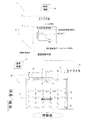
まず図2を用いて、本発明の一実施形態であるミント精製装置を備えたミント精製システムの概略を説明する。そのミント精製システム1は、冷却庫2およびその冷却庫の上部の開口を塞ぐ蓋体3からなるミント精製装置20を有している。そのミント精製装置20の冷却庫2内には、粗製メントール油を満たした複数の結晶缶30が載置されている。
そのミント精製システム1は、粗製メントール油を放冷あるいは強制冷却して缶底側から冷却すべく、缶底側から冷却庫2の底板からの伝熱で冷却が行え、缶頭側からは冷却も加熱も行えるようにして、缶底からの晶析の速度、いわば晶析の前線Zを緩やかに進行させるようにして、l(エル)−メントールを缶底側から所望の速度でゆっくりと晶析させるものである。
<Embodiment>
"1. Outline of mint purification system"
First, an outline of a mint purification system including a mint purification apparatus according to an embodiment of the present invention will be described with reference to FIG. The
The
例えば、そのようなシステムの一例として、前記ミント精製システム1は前記蓋体3の下方、結晶缶30の粗製ハッカ油液面上方空間の上側にプローブ部があり、上方空間の庫内温度を計測して温度計測信号(温度情報)5aを送出する温度センサ4bと、あらかじめ設定される時刻情報5bにより動作するタイマ手段5と、そのタイマ手段5からのトリガとなる信号に基づいて、予め演算式で登録された設定温度変更情報6aから下位に存在する温度制御手段7へカスケード的に設定値を与える設定温度変更手段6と、その設定温度変更手段6から設定値として与えられる設定温度値(設定された温度情報)17bおよび温度センサ4bから送出された温度計測信号5aに基づいて、例えば変化する設定温度値17bと温度計測値5aとの偏差に基づいて、前記ヒータの出力を制御する温度制御手段7とをさらに備えている。
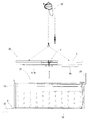
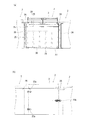
また、前記蓋体3には、装置内の空気を攪拌するように、羽根下部の空気を羽根上方へ動かすことで冷却庫上部空間の空気を伝導板9の表面をなめながら冷却庫側板へ空気を流すファン8が設けられている。さらに、伝導板9と蓋体本体との間にはヒータ4aが設けられている。前記蓋体3は昇降装置により昇降される(図1参照)。図1では、昇降装置の一例として、チェーンブロック32が用いられている。
ここで、前記タイマ手段5、設定温度変更手段6および温度制御手段7は制御部31を構成する。
For example, as an example of such a system, the
In addition, the
Here, the timer means 5, the set temperature changing means 6 and the temperature control means 7 constitute a
ここで、「時刻情報」とは、時刻、所定の時刻から経過した時間およびそれらに換算できる値を含む概念である。本実施形態では、晶析にかかる時間は100〜140時間である。
さらに、「タイマ手段」とは、実施形態では図9aのステップS1が対応する。
さらに、「温度制御手段」とは、実施形態では図9aのステップS3が対応する。
Here, the “time information” is a concept including a time, a time elapsed from a predetermined time, and a value that can be converted into them. In this embodiment, the time required for crystallization is 100 to 140 hours.
Furthermore, “timer means” corresponds to step S1 of FIG.
Furthermore, “temperature control means” corresponds to step S3 in FIG. 9A in the embodiment.
「2.ハードウェア構成」
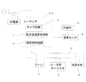
図3に示すように、この実施形態の制御部31には、例えばシーケンサが用いられている。
そのシーケンサ10は別に接続される外部PC12などでラダー回路としてタイマ回路や温度指示調節計に相当するPID制御の回路等を自在に設定可能なものである。そのシーケンサには、アナログ信号として、例えば1−5V信号を送出する温度センサ4bからの温度計測信号5aを、温度指示調節計に相当する温度制御手段7のPID回路への入力として回路を組み、温度制御手段7の上位設定温度変更手段6にもタイマ回路15のタイマ信号をトリガとして、あらかじめ記憶している設定温度変更手段6(ここでは設定温度変更演算式17、図3参照)に応じた設定温度出力を演算出力する回路11を設け、PID回路14である温度制御手段7に設定温度信号として例えば、設定温度値17bを入力するように組まれている。設定温度変更演算式17は、例えば、24時間毎に0.1〜1
0℃のいずれかの低下速度で、100〜140時間かけて設定温度を変更するなどの演算式となっている。
その温度制御手段7では、設定温度値17bと温度センサ4bからの温度計測値5aとの偏差を演算し、ヒータ出力を司るサイリスタなどへ、PID演算した結果として出力信号を送って制御する。
また、前記シーケンサ10からは計装線16が延びており、ファン8、ヒータ用サイリスタ13および冷却水弁19がそれぞれ連結されている。
上記実施形態では、図2に示す機能をシーケンサ10とラダープログラム18を用いて実現するようにしているが、その一部または全部(例えば制御部31)を盤機器および配線による制御回路によって実現するようにしてもよい。
“2. Hardware configuration”
As shown in FIG. 3, for example, a sequencer is used for the
The sequencer 10 can freely set a timer circuit or a PID control circuit corresponding to a temperature indicating controller as a ladder circuit with an
The calculation formula is such that the set temperature is changed over a period of 100 to 140 hours at any rate of 0 ° C.
The temperature control means 7 calculates the deviation between the set
An
In the above embodiment, the functions shown in FIG. 2 are realized by using the sequencer 10 and the ladder program 18, but part or all of the functions (for example, the control unit 31) are realized by a control circuit using panel equipment and wiring. You may do it.
「3.ミント精製装置」
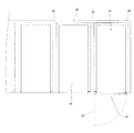
図1および図4を用いて本発明のミント精製装置20および冷却庫2の概略を説明する。前記ミント精製装置20は、例えば、天井および前面に開口を有している冷却庫2と、その冷却庫2の天井の開口21を閉じる前記蓋体3と、前面の開口22(図4も併せて参照)を開閉するドア23とを備えている。前面を開閉できることで、作業員が冷却庫2の奥側から順に結晶缶を順に配置しやすくなっている。
本実施形態に用いる冷却庫2の内のりの大きさは、例えば幅が1200mm〜1800mm、長さが2100mm〜3000mmであり、高さが1000mm〜1500mmのもので、250〜300mm角の平面、高さ500〜800mmの寸法の結晶缶の倍数の寸法があればよい。
なお、図4では3つのミント精製装置が連結されている様子を示しているが、1つでもよいし、4つ以上の装置を連結してもよい。
"3. Mint purification equipment"
The outlines of the
The inner size of the
Although FIG. 4 shows a state in which three mint purification apparatuses are connected, one may be used, or four or more apparatuses may be connected.
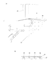
前記冷却庫2は、例えば、全体としてその外形が直方体状であり、断熱板26(図5a参照)の表裏をステンレスの板材25で挟んだ部材で構成されている。これにより、図4に示すように、前記冷却庫の底面24およびその側面の側縁付近から立設する3枚の側面25を形成している。その側面25は前記底面24の左右および後ろの側の3方を囲うように立設している。図5aに示すように、隣接する冷却庫2、2の間のそれぞれの側壁25、25の間には、断熱板26が設けられている。さらに、天井開口21の周辺のフレームには、隣接する冷却庫2、2、2を連結するように平板状の断熱板26、26が設けられている。この断熱板26、26の上に前記蓋体3が載置され、前記開口21(図4参照)は閉じられる。さらに前記底面24は、建屋のモルタルで形成された床27の上面から僅かに隙間を空けて配置されている。ただし接していてもよい。
The
図6aに示すように、前記床27の内部には冷却管28が敷設され、冷却庫2の底面24の金属板に伝熱可能に設置され、モルタルで埋められている。前記冷却管28は、モルタルの表層付近に埋設されている(図6b参照)。本実施形態では、その冷却管28に流す冷媒としてブライン(不凍液)を用いており、図示しない配管により循環される冷媒は、冷凍機出口温度で約1℃に温調されている。つまり、冷却庫2の冷却管28の供給温度も約1℃になっている。なお、温度をもう少し高く設定する場合は、ブラインではなく冷水を冷媒として用いてもよい。
図5aに戻って、前記冷却庫2の側面25の上部の内面には、上方の冷却管29が設けられている。その上方の冷却管29にも同様にブライン又は冷水が流されており、前記図示しない配管により循環され冷凍機で温度調整されている。この上方の冷却管29で冷却することにより、ヒータだけでは精密な温度調整が難しい場合、例えば、晶析工程の最終段階において、ヒータ出力を弱めるだけですぐに結晶缶30の缶頭部分を冷却し、缶頭付近のl−メントールを晶析させることができる。
本実施形態では、ブライン又は冷水の温度は−5℃〜7℃のうちのいずれかの供給温度に設定され、冷却庫2にて冷熱を与えて温まった冷媒は冷凍機で再び冷却されるのである
。
As shown in FIG. 6 a, a cooling
Returning to FIG. 5 a, an
In the present embodiment, the temperature of the brine or the cold water is set to any supply temperature of −5 ° C. to 7 ° C., and the refrigerant that has been warmed by the
前記結晶缶30は、ステンレス製で、上下に長い有底筒状の缶である。その缶の平面形状は上方に向けて次第に大きくなっており、晶析した結晶を上方に抜き取りやすくなっている。
そして、本実施形態においては、結晶缶30の大きさは、例えば、缶底において一辺が220mm〜270mmの正方形であり、高さが500mm〜800mmであり、缶頭において一辺が250mm〜300mmの正方形である。
また、図5bに示すように、前記ドア23は、その一側端付近をヒンジ23a、23aで止めて、他端にロック機構付き取っ手23bが設けられ水平方向に開閉可能に構成されたものである。そのドア23を開けると、前記冷却庫2の前面の開口22(図5a参照)を通じて結晶缶30(図5a参照)へのアクセスおよび結晶缶30の出し入れなどが容易になる。
The crystal can 30 is made of stainless steel and is a bottomed cylindrical can that is long in the vertical direction. The planar shape of the can gradually increases upward, and the crystallized crystal can be easily extracted upward.
In the present embodiment, the size of the crystal can 30 is, for example, a square having a side of 220 mm to 270 mm on the bottom of the can, a height of 500 mm to 800 mm, and a square having a side of 250 mm to 300 mm on the can head. It is.
Further, as shown in FIG. 5b, the
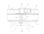
図7に示すように、前記蓋体3は、中空の本体部3aを備えている。その本体部3aには前記ファン8が設けられている。
前記本体部の中央付近には貫通孔3bが形成されており、その貫通孔3bにシリコーン樹脂製のブッシュ3cが設けられている。
As shown in FIG. 7, the
A through
前記ファン8は、モータ8aと、そのモータの回転軸8bを介して回転する羽根8cとを備えている。そのモータ8aは、本体部3aの上面にプレート3dを介して固定され、前記貫通孔3b内に通されたブッシュ3cを介して回転軸8bを下方に延ばしている。そして、回転軸8bの下面に突出した部位に羽根8cが取り付けられている。
前記プレート3dおよびブッシュ3cは、例えばシリコーン樹脂製の耐熱部材が用いられている。
また、その羽根8cの周囲には、羽根との接触を防止するためのファンガード8dが取り付けられている。
The
For the
A
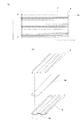
図8aに示すように、本実施形態の前記伝導板9は、例えば角波板と呼ばれる板鋼材である。その角波板9の断面形状(図8b参照)は、台形状が互い違いの向きで連続する形状である。それらの台形は上辺が下辺より短く、左右対称な形状である。その角波板9は、本体部3aの下面に設置されている。
本実施形態のヒータ4aとしては、例えばニクロム線を金属パイプで包んだシーズヒータが用いられている。図8bに示すように、前記ヒータ4aは、角波板9の波形状の上方から見た溝内に収容して、本体部3aの下面を前後に往復しながら、左右方向に延設されている。これにより、シーズヒータの線としての加熱ではなく、伝熱のよい金属である角波板9全面に伝熱して、「面」として蓋体下方の本体部3aの下面のほぼ全面をムラなく温めることができる。そして、そのヒータ4aを前記角波板9とで挟持するようにヒータ4aの上方に第2の角波板9が重ねられる。
前記角波板9は、ステンレス製であり、本体部3aの下面をほぼ覆っている。その角波板9は、ヒータ4aから放射される熱をすぐに平面的に伝熱させ、熱容量により一部を蓄えながら、全面に輻射熱を発生する。その輻射の面が大きいと、温度ムラを抑える効率が高い。
本実施形態では、シーズヒータであるヒータ4aの表面温度は150〜200℃あるが、伝熱により角波板9の表面温度は40〜50℃で大面積となり、温度分布や温度制御性にとって設定温度に近くなるため有利となる。
As shown in FIG. 8a, the conductive plate 9 of the present embodiment is, for example, a plate steel material called a square wave plate. The cross-sectional shape of the square wave plate 9 (see FIG. 8b) is a shape in which trapezoidal shapes are continuous in alternate directions. These trapezoids are symmetrical with the upper side shorter than the lower side. The square wave plate 9 is installed on the lower surface of the
As the
The square wave plate 9 is made of stainless steel and substantially covers the lower surface of the
In this embodiment, the surface temperature of the
図1に戻って、前記温度センサ4bは、本実施形態では、蓋体3の側縁付近からその下面側へ通され、その下面側でファン8側に延ばされる棒状の先端プローブ部が設けられ、そのファン8までの半分程度の行程の位置に配置されている。この温度センサ4bは、例
えば銅コンスタンタンの熱電対でも良く、支持可能な棒状の部材に沿わせて、先端の半田付け玉部をプローブ部として設置しても良い。そして、その配置される高さ位置は、ファン8と同程度の高さ位置である。前記ファン8は送風ファンであり、伝導板9に向けて上向きに送風している。この流れのほうが、角波板9をなめながら冷却庫側板に沿って結晶缶へゆっくりと流れ出すので温度分布上有利となる。ただし、逆向きに送風してもよい。
ここで、前記ファンにより攪拌される空気は、少なくとも上方の空気のことである。すなわち、冷却庫2の空気はそのほとんどが、蓋体の下面と結晶缶30の上面との間の空間に存在する。隣接する結晶缶30の間には隙間があるが、その隙間部分、特に缶底側の隙間の空気まで攪拌することは難しい。
Returning to FIG. 1, in the present embodiment, the
Here, the air stirred by the fan is at least the air above. That is, most of the air in the
「4.フローチャート」
次に、図9aを用いて、ミント精製システム1で用いられる制御部31(図3参照)での演算処理の流れの一例を示すフローチャートを説明する。
"4. Flow chart"
Next, a flowchart illustrating an example of a flow of arithmetic processing in the control unit 31 (see FIG. 3) used in the
(S1)シーケンサ10(図3参照)は、制御部31の電源が入っている際には常に出力されている、温度センサ4bから送出される温度計測信号5aを受け入れているが、温度制御手段7については、朝は動作させていない。そして、別に設定されているか、毎日の作業に入る際の入力信号による所定のタイミングでタイマ手段5から設定温度変更手段6にトリガ信号5bが入力される。
(S2)すると、予め記憶されている設定温度変更演算式17の演算が開始され、予め演算式として登録された設定温度変更情報6a(図2参照)から下位に存在する温度調節計手段7へカスケード的に設定値17bを与える。
(S1) The sequencer 10 (see FIG. 3) accepts the
(S2) Then, calculation of the preset temperature change arithmetic expression 17 stored in advance is started, and from the preset temperature change information 6a (see FIG. 2) registered in advance as the arithmetic expression to the temperature controller means 7 existing at the lower level. The
(演算式)
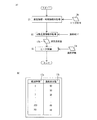
図9bに設定温度変更演算式の概念の例を示す。その設定温度変更演算式17(図2参照)には、冷却を開始からの経過時間17aに対応する設定温度変更信号17bとの関係が、一次曲線式や2次曲線式として記載されている。なお、演算式17で演算を行う代わりに、図9bに示すテーブルに演算式17の演算結果を予め登録しておいて、その登録されたデータに基づいて、設定温度値17bを取得してもよい。
(Arithmetic expression)
FIG. 9b shows an example of the concept of the set temperature change arithmetic expression. In the set temperature change calculation expression 17 (see FIG. 2), the relationship with the set
(S3)設定値を与えられた温度制御手段7は、冷却庫2の上方付近の温度情報の温度計測信号5aと設定値17bに基づく信号との偏差に基づいて、ヒータの出力を司るサイリスタなどに出力信号を送出することで、ヒータ4a(図1参照)の温度を制御する。
例えば、ある時刻における測定した温度が設定温度変更演算式17の演算結果の設定値温度より高いときは、ヒータ4aの温度を下げ、逆に低いときはヒータ4aの温度を上げることにより、温度が所定の温度カーブに沿って変化するように制御する。
(S3) The temperature control means 7 given the set value is a thyristor that controls the output of the heater based on the deviation between the
For example, when the measured temperature at a certain time is higher than the set value temperature of the calculation result of the set temperature change calculation equation 17, the temperature of the
「5.製造過程」
次に、本発明のミント精製装置2を用いて1−メントールを晶析する概略工程の一実施形態を説明する。
(1)作業員が予め冷却管にブラインを通水し、床の温度を冷却開始の所定の温度にする。
(2)金庫の蓋体をチェーンブロックで吊り上げ、そして前面の開口を塞いでいるドアを開けて金庫の前面の開口から入って、金庫に収容されている結晶缶に粗製ハッカ油を満たす、あるいは、粗製ハッカ油が入った結晶缶を配置する。
(3)前面の開口側から粗製ハッカ油の種を結晶缶内に入れる。なお、この種は微結晶あるいは急速に冷凍して得てもよい。
(4)チェーンブロックを用いて蓋体を下降させ、金庫の天井の開口を閉じ、そして前面の開口のドアを閉じる。
(5)冷却管にブラインなどの冷媒を流すと共に、ヒータおよびファンを駆動させ、予め
設定された所定のタイマ回路の時刻をトリガとして制御部を作動させる。
(6)結晶が得られた後、金庫の蓋体をチェーンブロックで上昇させて、前面の開口を塞いでいるドアを開ける。
"5. Manufacturing process"
Next, an embodiment of a schematic process for crystallizing 1-menthol using the
(1) The worker passes brine through the cooling pipe in advance, and sets the floor temperature to a predetermined temperature at which cooling starts.
(2) Lift the lid of the safe with a chain block and open the door closing the front opening and enter through the opening on the front of the safe to fill the crude canned oil into the crystal can contained in the safe, or Place a crystal can containing crude mint oil.
(3) Put seeds of crude mint oil into the crystal can from the opening side of the front surface. This species may be obtained by microcrystallization or rapid freezing.
(4) The lid is lowered using the chain block, the opening of the ceiling of the safe is closed, and the door of the front opening is closed.
(5) A coolant such as brine is allowed to flow through the cooling pipe, and the heater and the fan are driven, and the controller is operated using a preset time of a predetermined timer circuit as a trigger.
(6) After the crystal is obtained, the lid of the safe is raised by the chain block, and the door closing the front opening is opened.
<比較例>
伝導板を備えておらず、ヒータが蓋体に直接に取り付けられた図10aのミント精製装置34を比較例とする。このものの内部構造は、上述したミント精製装置2とほぼ同じであるので図示しない。
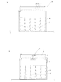
図10aは比較例のミント精製装置34の内部において、粗製ハッカ油が結晶する様子を示す模式図である。図中の二点鎖線は前線Zであり、缶底からその線の位置まで結晶化がほぼ進んでいることを示す。図の前線Zの下方では粗製ミント油から1−メントールが晶析した固形状部であり、その上方は未だ晶析していない液状部である。なお、前記前線Zは固形状部と液状部を模式的に表しているものであり、明確にその前線で固形状部と液状部が分離されているわけではない。
図に示すように、装置の中央付近では前記前線Zが下方に凸に湾曲しており、端部近辺では上がっている。このように、結晶缶30毎に結晶の形成にばらつきがある。このばらつきを示す湾曲した前線が結晶缶30の上方にゆっくりと移動していく。このため、端部近辺では理想的な晶析速度より早く晶析が進むので、結晶の生成効率が低下する。
一方、図10bには伝導板を備えているミント精製装置2(図3参照)において、粗製ハッカ油の結晶化する様子を示す。図に示すように、前線Zが高さ方向にほぼ揃っており、このまま次第に上方に向かって進行する。
<Comparative example>
A
FIG. 10a is a schematic view showing a state in which crude mint oil is crystallized inside the
As shown in the figure, the front line Z is curved downward and convex near the center of the apparatus, and is raised near the end. As described above, the crystal formation varies for each crystal can 30. A curved front showing this variation moves slowly above the crystal can 30. For this reason, the crystallization proceeds faster than the ideal crystallization speed in the vicinity of the edge, so that the crystal generation efficiency decreases.
On the other hand, FIG. 10b shows a state in which crude mint oil is crystallized in the mint refining device 2 (see FIG. 3) provided with a conductive plate. As shown in the figure, the front lines Z are substantially aligned in the height direction, and gradually proceed upward as they are.
<他の実施形態>
図1に戻って、結晶缶30の底付近の温度を温度センサ35で検出して、その温度が所定の値であることを冷却開始の合図としてもよい。
<Other embodiments>
Returning to FIG. 1, the temperature near the bottom of the crystal can 30 may be detected by the
<変形例>
前記ミント精製装置の材質は、強度が高く、錆が発生しにくい材質として、ステンレスを用いるのがよい。
<Modification>
As the material of the mint refining device, it is preferable to use stainless steel as a material having high strength and hardly generating rust.
前記ファン8としては、ミント精製装置2内の空気を攪拌するものであればよく、少なくとも蓋体3と結晶缶30の上面の空間の空気を攪拌できるものである。なお、伝導板9側から空気を吸引して結晶缶側に吐き出すものでもよい。
前記ヒータとしては、シーズヒータの他、熱せられた熱媒体を管路に流すものなど公知のものを用いることができる。また、シーズヒータの周囲にフィンを取り付けたフィンヒータを用いてもよい。
温度センサ5としては、熱電対やサーミスタなど従来公知のものを用いることができる。
前記結晶缶30は底側から冷却管28の冷却水で冷却されているが、冷却水を用いずに、放冷により晶析を行ってもよい。
The
As the heater, in addition to a sheathed heater, a known heater such as a heater that allows a heated heat medium to flow through a pipe line can be used. Moreover, you may use the fin heater which attached the fin around the sheathed heater.
As the
The crystal can 30 is cooled from the bottom with the cooling water of the cooling
前記角波板9としては、例えば、その断面形状が三角、四角などを含む多角形状、さらには湾曲形状、それらを組み合わせた形状にしたものでもよい。このような溝を有する断面形状であると、その溝内にヒータを収容する通すスペースを設けつつ、輻射熱を発生させる表面積を大きくできる。
第2の伝導板は、ヒータを押える機構を有するものであれば、伝導板と同じ形状にする必要はない。さらに、エンボスのように細かな凹凸が形成されているものなど、輻射熱を発生させる表面積を大きくしてもよい。
さらに、伝導板9をセラミックスなど輻射熱を放熱する材質で形成したり、それを表面に担持させてもよい。
また、第2の伝導板を用いなくてもよい。その場合は、伝導板9にヒータ4aを取り付ける。
As the square wave plate 9, for example, the cross-sectional shape thereof may be a polygonal shape including a triangle, a square or the like, a curved shape, or a combination thereof. When the cross-sectional shape has such a groove, it is possible to increase the surface area for generating radiant heat while providing a space for accommodating the heater in the groove.
The second conductive plate need not have the same shape as the conductive plate as long as it has a mechanism for pressing the heater. Further, the surface area for generating radiant heat, such as embossed ones with fine irregularities, may be increased.
Further, the conductive plate 9 may be formed of a material that radiates radiant heat, such as ceramics, or may be supported on the surface.
Further, the second conductive plate may not be used. In that case, the
前記チェーンブロック32の他に、蓋体3を吊ることにより昇降させるクレーンや、蓋体3を下方からピストンで押し上げるリフタなどを昇降装置として用いてもよい。さらに、昇降させた蓋体を前記天井の開口の上空を空けるように水平に移動できるものでもよい。水平に移動できると上昇させた蓋体3を別の場所に降ろすことができ、不具合や洗浄の際に蓋体の修理、交換、メンテナンスなどが容易になる。
In addition to the
1 ミント精製システム
2 冷却庫(金庫)
3 蓋体
3a 本体部
3b 貫通孔
3c ブッシュ
3d プレート
4a ヒータ
4b 温度センサ
5 タイマ手段
5a 温度情報(温度計側値)
6 設定温度変更手段
6a 設定温度変更情報
7 温度制御手段
8 ファン
8a モータ
8b 回転軸
8c 羽根
8d ファンガード
9 伝導板(角波板)
10 シーケンサ
11 設定温度変更手段の演算回路
12 外部PC
13 サイリスタなどのヒータ出力調整部
14 温度制御手段のPID演算回路
15 タイマ回路
16 計装線
17 設定温度変更演算式
17a 経過時間
17b 設定温度値
18 ラダープログラム
19 冷却水弁
20 ミント精製装置
21 天井の開口
22 前面の開口
23 ドア
23a ヒンジ
23b 取っ手
24 底面
25 側面
26 断熱板
27 床
28 下方の冷却管
29 上方の冷却管
30 結晶缶
31 制御部
32 チェーンブロック
33 蓋体ユニット
34 比較例
35 温度センサ
Z 前線
1
3
6 Set temperature change means 6a Set temperature change information 7 Temperature control means 8
10
13 Heater
Claims (6)
前記結晶缶を収容し、底板の下面にブライン又は冷水を流通する冷却管を底板に伝熱可能に配置する冷却庫と、
その冷却庫の上部の開口を塞ぐ蓋体とからなり、
その蓋体の前記冷却庫に面する裏面に、ヒータと、そのヒータの熱が伝導する伝導板と、その伝導板の下方に配置されるファンとが設けられている、
ミント精製装置。 A mint refining device that cools or cools crude mint oil in a crystal can to crystallize l-menthol,
A refrigerator that houses the crystal can and arranges a cooling pipe for circulating brine or cold water on the bottom surface of the bottom plate so that heat can be transferred to the bottom plate;
It consists of a lid that closes the upper opening of the refrigerator,
A heater, a conductive plate that conducts heat of the heater, and a fan that is disposed below the conductive plate are provided on the back surface of the lid facing the refrigerator.
Mint purification equipment.
前記蓋体の下方でハッカ油液面より上の空間温度を含む温度情報を検知する温度センサと、
その温度センサから得られた温度情報に基づいて、前記ヒータの温度を制御して、結晶缶の底部と結晶缶の液面との温度差を設定制御しながら、結晶缶に入れられたハッカ油が缶底側から所望の冷却速度(凝固速度)になるように前記ヒータを制御する制御部とを備えている、ミント精製システム。 A mint purification apparatus according to any one of claims 1 to 5,
A temperature sensor for detecting temperature information including a space temperature above the mint oil liquid level below the lid,
Based on the temperature information obtained from the temperature sensor, the temperature of the heater is controlled to set and control the temperature difference between the bottom of the crystal can and the liquid level of the crystal can, and the mint oil contained in the crystal can And a control unit that controls the heater so that a desired cooling rate (solidification rate) is obtained from the bottom side of the can.
Priority Applications (1)
| Application Number | Priority Date | Filing Date | Title |
|---|---|---|---|
| JP2015072534A JP6457314B2 (en) | 2015-03-31 | 2015-03-31 | Mint purification equipment and mint purification system |
Applications Claiming Priority (1)
| Application Number | Priority Date | Filing Date | Title |
|---|---|---|---|
| JP2015072534A JP6457314B2 (en) | 2015-03-31 | 2015-03-31 | Mint purification equipment and mint purification system |
Publications (2)
| Publication Number | Publication Date |
|---|---|
| JP2016190821A true JP2016190821A (en) | 2016-11-10 |
| JP6457314B2 JP6457314B2 (en) | 2019-01-23 |
Family
ID=57246507
Family Applications (1)
| Application Number | Title | Priority Date | Filing Date |
|---|---|---|---|
| JP2015072534A Active JP6457314B2 (en) | 2015-03-31 | 2015-03-31 | Mint purification equipment and mint purification system |
Country Status (1)
| Country | Link |
|---|---|
| JP (1) | JP6457314B2 (en) |
Cited By (2)
| Publication number | Priority date | Publication date | Assignee | Title |
|---|---|---|---|---|
| CN113881504A (en) * | 2021-11-05 | 2022-01-04 | 安徽恒达药业有限公司 | Freeze-out device is used in menthol production |
| CN115779483A (en) * | 2022-11-17 | 2023-03-14 | 安徽海华科技集团有限公司 | Synthetic L-menthol crystallization purification system and purification method thereof |
Citations (5)
| Publication number | Priority date | Publication date | Assignee | Title |
|---|---|---|---|---|
| JPH06194076A (en) * | 1992-08-31 | 1994-07-15 | Kyoraku Co Ltd | Heat accumulating body |
| JP2001524657A (en) * | 1997-11-24 | 2001-12-04 | アイソセーフ リミテッド | container |
| JP2002514735A (en) * | 1998-05-12 | 2002-05-21 | アメリゴン インコーポレイティド | Thermoelectric heat exchanger |
| JP2004147548A (en) * | 2002-10-30 | 2004-05-27 | Best:Kk | Method for freezing frozen commodity |
| JP2012517993A (en) * | 2009-02-17 | 2012-08-09 | 長岡実業株式会社 | Method and apparatus for producing natural l-menthol |
-
2015
- 2015-03-31 JP JP2015072534A patent/JP6457314B2/en active Active
Patent Citations (5)
| Publication number | Priority date | Publication date | Assignee | Title |
|---|---|---|---|---|
| JPH06194076A (en) * | 1992-08-31 | 1994-07-15 | Kyoraku Co Ltd | Heat accumulating body |
| JP2001524657A (en) * | 1997-11-24 | 2001-12-04 | アイソセーフ リミテッド | container |
| JP2002514735A (en) * | 1998-05-12 | 2002-05-21 | アメリゴン インコーポレイティド | Thermoelectric heat exchanger |
| JP2004147548A (en) * | 2002-10-30 | 2004-05-27 | Best:Kk | Method for freezing frozen commodity |
| JP2012517993A (en) * | 2009-02-17 | 2012-08-09 | 長岡実業株式会社 | Method and apparatus for producing natural l-menthol |
Cited By (3)
| Publication number | Priority date | Publication date | Assignee | Title |
|---|---|---|---|---|
| CN113881504A (en) * | 2021-11-05 | 2022-01-04 | 安徽恒达药业有限公司 | Freeze-out device is used in menthol production |
| CN113881504B (en) * | 2021-11-05 | 2023-07-21 | 安徽恒达药业有限公司 | Freezeout device is used in menthol production |
| CN115779483A (en) * | 2022-11-17 | 2023-03-14 | 安徽海华科技集团有限公司 | Synthetic L-menthol crystallization purification system and purification method thereof |
Also Published As
| Publication number | Publication date |
|---|---|
| JP6457314B2 (en) | 2019-01-23 |
Similar Documents
| Publication | Publication Date | Title |
|---|---|---|
| TWI363109B (en) | ||
| JP6457314B2 (en) | Mint purification equipment and mint purification system | |
| EP1669668A1 (en) | Vapor producing device and cooker with the same | |
| RU2012113230A (en) | METHOD AND DEVICE FOR GROWING SAPPHIRE SINGLE CRYSTALS | |
| Sivaraj et al. | Analysis of thermo-magnetic convection and entropy generation of Al2O3-water nanofluid in a partially heated wavy electronic cabinet | |
| WO2013112231A1 (en) | Method of producing monocrystalline silicon | |
| JP2014521577A5 (en) | ||
| CN109913951A (en) | A silicon carbide single crystal growth device | |
| CN206762313U (en) | A kind of crystallizing pan for producing calcium gluconate | |
| CN103952759A (en) | Method and device for preparing calcium fluoride crystal by using a method of declining crucible with built-in heating body | |
| CN205658253U (en) | Cooling cooling chamber is preserved to biomaterial low temperature | |
| CN101481825B (en) | Crystal growth furnace with convection type heat dissipation structure | |
| KR20110056635A (en) | Polycrystalline Silicon Ingot Manufacturing Equipment for Solar Cell | |
| JP2004035394A (en) | Method for growing calcium fluoride single crystal | |
| TWI890441B (en) | Single crystal growth device | |
| CN202323114U (en) | Cooling device for bottom of polycrystalline silicon ingot casting furnace and polycrystalline silicon ingot casting furnace using cooling device | |
| TW201303095A (en) | A crystal growing installation | |
| Kokh et al. | Numerical modeling of melt flows in vertical Bridgman configuration affected by a rotating heat field | |
| CN105696072A (en) | Sapphire crystal growth furnace | |
| RU107459U1 (en) | WAX REMOVER | |
| PL411695A1 (en) | Method for producing a long silicon carbide crystals from gaseous phase | |
| CN204699434U (en) | A kind of pyrrole ketone synthesis crystallization kettle | |
| CN103603032B (en) | Control the method for crystallization velocity in silicon ingot casting | |
| JP2014227586A (en) | Method and apparatus for refining aluminum | |
| CN215873353U (en) | Boxed lactone bean curd production equipment |
Legal Events
| Date | Code | Title | Description |
|---|---|---|---|
| A621 | Written request for application examination |
Free format text: JAPANESE INTERMEDIATE CODE: A621 Effective date: 20171027 |
|
| A977 | Report on retrieval |
Free format text: JAPANESE INTERMEDIATE CODE: A971007 Effective date: 20180711 |
|
| A131 | Notification of reasons for refusal |
Free format text: JAPANESE INTERMEDIATE CODE: A131 Effective date: 20180807 |
|
| A521 | Request for written amendment filed |
Free format text: JAPANESE INTERMEDIATE CODE: A523 Effective date: 20181009 |
|
| TRDD | Decision of grant or rejection written | ||
| A01 | Written decision to grant a patent or to grant a registration (utility model) |
Free format text: JAPANESE INTERMEDIATE CODE: A01 Effective date: 20181204 |
|
| A61 | First payment of annual fees (during grant procedure) |
Free format text: JAPANESE INTERMEDIATE CODE: A61 Effective date: 20181220 |
|
| R150 | Certificate of patent or registration of utility model |
Ref document number: 6457314 Country of ref document: JP Free format text: JAPANESE INTERMEDIATE CODE: R150 |