JP2016192526A - Rack for equipment housing and installation method for rack for equipment housing - Google Patents
Rack for equipment housing and installation method for rack for equipment housing Download PDFInfo
- Publication number
- JP2016192526A JP2016192526A JP2015073086A JP2015073086A JP2016192526A JP 2016192526 A JP2016192526 A JP 2016192526A JP 2015073086 A JP2015073086 A JP 2015073086A JP 2015073086 A JP2015073086 A JP 2015073086A JP 2016192526 A JP2016192526 A JP 2016192526A
- Authority
- JP
- Japan
- Prior art keywords
- back plate
- storage rack
- cable
- cables
- equipment
- Prior art date
- Legal status (The legal status is an assumption and is not a legal conclusion. Google has not performed a legal analysis and makes no representation as to the accuracy of the status listed.)
- Granted
Links
Images


Landscapes
- Insertion, Bundling And Securing Of Wires For Electric Apparatuses (AREA)
Abstract
【課題】薄型に成形したとしてもケーブルの接続や機器の固定を容易に行うことができる機器収納用ラック、及び機器収納用ラックの設置方法を提供する。【解決手段】背板3に複数の角孔11、11・・を穿設しており、機器に接続させるべく背板3の前面側に引き込まれたケーブルK、K・・に対し、角孔11、11・・を挿通させる等して結束バンド30を巻き付けることにより、ケーブルK、K・・を束ねた状態でケーブル仮止め部に仮止め可能としている。したがって、たとえ機器収納用ラック1が奥行きのない薄型に成形されていたとしても、他の機器に接続するためのケーブルK、K・・が邪魔とならず、ケーブルK、K・・の接続作業やケーブルK、K・・が接続された状態にある機器の固定作業を容易に行うことができる。【選択図】図4Provided are a device storage rack and a device storage rack installation method capable of easily connecting cables and fixing devices even if they are formed thin. A plurality of square holes 11, 11,... Are formed in the back plate 3, and the square holes are provided for the cables K, K,. By winding the binding band 30 by inserting 11, 11,..., The cables K, K,... Can be temporarily fixed to the cable temporary fixing portion. Therefore, even if the equipment storage rack 1 is formed thin and thin, the cables K, K ... for connecting to other equipment do not get in the way, and the connection work of the cables K, K ... And the fixing operation | work of the apparatus in the state to which the cables K and K * were connected can be performed easily. [Selection] Figure 4
Description
本発明は、たとえばラックマウントタイプの電気機器等を収納可能な機器収納用ラック、及び機器収納用ラックの設置方法に関するものである。 The present invention relates to a device storage rack capable of storing, for example, a rack mount type electric device and a method for installing the device storage rack.
近年、ラックマウントタイプの電気機器や通信機器を収納する機器収納用ラックは、住宅の壁面内に埋設されることがある。そして、そのような埋設タイプの機器収納用ラックは、たとえば特許文献1に記載されているように、一方向の長さに比べて直交する他方向の長さが短い所謂薄型に成形されることが多い。 2. Description of the Related Art In recent years, equipment storage racks that store rack mount type electrical equipment and communication equipment are sometimes embedded in the wall surface of a house. And such an embedded type equipment storage rack is formed into a so-called thin shape in which the length in the other direction perpendicular to the length in one direction is shorter than the length in one direction, as described in Patent Document 1, for example. There are many.
機器収納用ラック内に各種機器を収納するにあたっては、各機器に接続するケーブルを機器収納用ラック内に予め引き込んでおき、各機器と対応するケーブルとを接続した後、固定具等を利用して各機器を機器収納用ラック内に固定することになる。しかしながら、上述したような薄型の機器収納用ラックであると、ラック内のスペースが狭いため、ケーブルの接続や機器の固定に際して、予め引き込んである他の機器のためのケーブルが邪魔になり、ケーブルの接続作業や機器の固定作業が煩わしくなるという問題が生じる。 When storing various devices in the device storage rack, draw cables in advance into the device storage rack, connect each device to the corresponding cable, and then use fixtures. Thus, each device is fixed in the device storage rack. However, in the case of a thin equipment storage rack as described above, since the space in the rack is narrow, the cable for other equipment that has been drawn in beforehand becomes an obstacle when connecting the cable or fixing the equipment. There arises a problem that the connecting work and the fixing work of the apparatus become troublesome.
そこで、本発明は、上記問題に鑑みなされたものであって、薄型に成形したとしてもケーブルの接続や機器の固定を容易に行うことができる機器収納用ラック、及び機器収納用ラックの設置方法を提供しようとするものである。 Therefore, the present invention has been made in view of the above-described problem, and an apparatus storage rack capable of easily connecting a cable and fixing an apparatus even when the apparatus is thinly formed, and a method for installing the apparatus storage rack Is to provide.
上記目的を達成するために、本発明のうち請求項1に記載の発明は、設置面に固定された背板に、少なくとも前後両側に開口する本体を、その後側の開口を前記背板で閉塞するように組み付けてなり、内部に各種機器を収納可能とした機器収納用ラックであって、前記背板に複数の孔が穿設されており、前記機器と接続するために前記機器収納用ラック内へ引き込んだケーブルに、結束バンドを前記孔に挿通させつつ巻き付けることにより、前記ケーブルを束ねた状態で前記背板に仮止め可能としたことを特徴とする。
請求項2に記載の発明は、請求項1に記載の発明において、前記背板の外周縁が、後側へ折り曲げられており、前記背板を前記設置面に固定した際、前記孔の後側に空間が形成されることを特徴とする。
また、上記目的を達成するために、本発明のうち請求項3に記載の発明は、複数の孔が穿設された背板に、少なくとも前後両側に開口する本体を、その後側の開口を前記背板で閉塞するように組み付けてなり、内部に各種機器が収納される機器収納用ラックを設置するための設置方法であって、前記背板を設置面に固定する第1工程と、前記背板の前面側に前記機器に接続するケーブルを引き込む第2工程と、結束バンドを、前記孔に挿通させつつ前記ケーブルに巻き付けることにより、前記ケーブルを束ねた状態で前記背板に仮止めする第3工程と、前記背板に前記本体を組み付けて前記機器収納用ラックを構成する第4工程と、前記ケーブルと前記機器とを接続した後、前記機器を前記機器収納用ラック内に固定する第5工程とを実行することを特徴とする。
In order to achieve the above object, the invention according to claim 1 of the present invention is such that a main body that opens at least on both the front and rear sides is closed to a back plate fixed to an installation surface, and a rear opening is closed with the back plate. An equipment storage rack that is assembled in such a manner that various kinds of equipment can be accommodated therein, and a plurality of holes are formed in the back plate, and the equipment storage rack is connected to the equipment. It is characterized in that the cable pulled in can be temporarily fixed to the back plate in a state in which the cable is bundled by winding the cable with the binding band being inserted through the hole.
According to a second aspect of the present invention, in the first aspect of the invention, the outer peripheral edge of the back plate is bent to the rear side, and when the back plate is fixed to the installation surface, A space is formed on the side.
In order to achieve the above object, the invention according to
本発明によれば、背板に複数の孔を穿設しており、機器収納用ラック内へ引き込んだケーブルを、結束バンドを用いて背板に仮止めすることができる。したがって、たとえ薄型に成形されていたとしても、他の機器に接続するケーブルが邪魔とならず、機器とケーブルとの接続作業やケーブルが接続された状態にある機器の固定作業を容易に行うことができる。
また、請求項2に記載の発明によれば、背板の外周縁が、後側へ折り曲げられており、背板を設置面に固定した際、孔の後側に空間が形成されるようになっているため、作業者は、結束バンドによるケーブルの仮止めを非常に容易に行うことができる。
According to the present invention, a plurality of holes are formed in the back plate, and the cable drawn into the equipment storage rack can be temporarily fixed to the back plate using the binding band. Therefore, even if it is molded thinly, cables that connect to other devices do not get in the way, and it is easy to connect devices and cables or to fix devices that are connected to cables. Can do.
According to the invention described in
以下、本発明の一実施形態となる機器収納用ラック、及び機器収納用ラックの設置方法について、図面にもとづき詳細に説明する。 Hereinafter, an apparatus storage rack and an apparatus storage rack installation method according to an embodiment of the present invention will be described in detail with reference to the drawings.
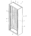
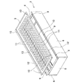
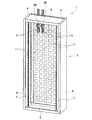
図1は、機器収納用ラック1を前側から示した斜視説明図である。図2は、本体2と背板3とを分解した状態にある機器収納用ラック1を前側から示した斜視説明図である。図3は、本体2と背板3とを分解した状態にある機器収納用ラック1を後側から示した斜視説明図である。図4は、引き込まれたケーブルK、K・・が仮止めされた状態にある機器収納用ラック1を示した斜視説明図である。
FIG. 1 is a perspective explanatory view showing the equipment storage rack 1 from the front side. FIG. 2 is a perspective explanatory view showing the equipment storage rack 1 in a state where the
機器収納用ラック1は、前後両側に開口する本体2と、本体2の後側の開口を覆うように組み付けられる背板3とを有する。本体2は、天板4、底板5、及び左右両側板6、6を正面視が四角形枠状となるように連結してなり、各側板6の内面側には、機器(図示せず)を固定するためのマウントアングル7等が設置されている。また、天板4及び底板5の前後幅は、両側板6、6の前後方向の長さよりも短くなっており、本体2と背板3とを組み付けた際、天板4と背板3との間、及び底板5と背板3との間にケーブルK、K・・を引き込むための引き込み口8が夫々形成されるようになっている。さらに、各側板6の後端面には、背板3に本体2を組み付けるための連結孔9、9・・が穿設されている。なお、本体2の前端縁には、図示しない前扉が上下方向を軸として片開き自在に蝶着可能となっている。
The equipment storage rack 1 has a
ここで、本発明の要部となる背板3について説明する。
背板3は、上下方向へ長い金属板の外周縁(上下左右側縁)を後側へ折り曲げて形成されるものであって、その表面は、多数の角孔11、11・・が略全面にわたり穿設された格子状に成形されている。そして、当該格子状部は、図4に示す如く、機器収納用ラック1内へ引き込まれたケーブルK、K・・を結束バンド30で束ねて仮止めするためのケーブル仮止め部として機能するようになっている。また、背板3の左右両側縁は、後側へ折り曲げられた後、更に左右外側へ折り返されており、当該折り返し部は、背板3を設置面に固定するための固定孔13、13・・を備えた設置代12として機能する。
Here, the
The
上記本体2と背板3とを有する機器収納用ラック1は、以下のようにして設置面に取り付けられ、各種機器が収納されて設置される。
まず、背板3を設置面に固定する。次に、背板3の上方や下方からケーブルK、K・・を背板3の前面側に引き込み、たとえば接続する機器毎等に分別する。そして、角孔11、11・・を挿通させる等してケーブルK、K・・の先端部近傍に結束バンド30を巻き付け、ケーブルK、K・・を束ねた状態でケーブル仮止め部に仮止めする。このとき、背板3の外周縁が後側へ折り曲げられていることにより、ケーブル仮止め部の後面が設置面から浮いた状態となっている(すなわち、角孔11、11・・の後側に空間が形成されている)ため、作業者は、結束バンド30を用いた仮止め作業を非常に容易に行うことができる。
The equipment storage rack 1 having the
First, the
さらに、ケーブルK、K・・の仮止め後、本体2を背板3に組み付けて機器収納用ラック1を形成する。このとき、ケーブルK、K・・を、本体2と背板3との間に形成される引き込み口8、8内に位置させ、当該引き込み口8、8を介して背板3の前面側(すなわち、機器収納用ラック1内)へ引き込まれた状態とする。最後に、各機器に対応するケーブルK、Kを接続した後、マウントアングル7、7へ固定する等して各機器を機器収納用ラック1内に収納する。このとき、他の機器に接続するケーブルK、K・・は背板3に仮止めされているため、機器とケーブルK、K・・との接続やケーブルK、Kが接続された機器の固定に際し、邪魔とならない。なお、各引き込み口8に関しては、パッキン(図示せず)を貼り付ける等して閉塞してもよい。
Further, after temporarily fixing the cables K, K..., The
以上のような構成を有する機器収納用ラック1によれば、背板3に複数の角孔11、11・・を穿設しており、機器に接続させるべく背板3の前面側に引き込まれたケーブルK、K・・に対し、角孔11、11・・を挿通させる等して結束バンド30を巻き付けることにより、ケーブルK、K・・を束ねた状態でケーブル仮止め部に仮止め可能としている。したがって、たとえ機器収納用ラック1が奥行きのない薄型に成形されていたとしても、他の機器に接続するためのケーブルK、K・・が邪魔とならず、ケーブルK、K・・の接続作業やケーブルK、K・・が接続された状態にある機器の固定作業を容易に行うことができる。
また、背板3の外周縁が、後側へ折り曲げられており、背板3を設置面に固定した際、角孔11、11・・の後側に空間が形成されるようにしているため、作業者は、結束バンド30によるケーブルK、K・・の仮止めを非常に容易に行うことができる。
According to the equipment storage rack 1 having the above-described configuration, a plurality of
Further, the outer peripheral edge of the
さらに、機器収納用ラック1を設置するにあたっては、まず背板3を設置面に固定し、当該背板3の前面側にケーブルK、K・・を引き込み、結束バンド30を、角孔11、11・・に挿通させつつケーブルK、K・・に巻き付けることにより、ケーブルK、K・・を束ねた状態で背板3に仮止めした後、背板3に本体2を組み付けて機器収納用ラック1を構成し、ケーブルK、K・・と機器とを接続してから機器を機器収納用ラック1内に固定する。したがって、作業者は、ケーブルK、K・・の接続作業やケーブルK、K・・が接続された状態にある機器の固定作業を容易に行うことができる。
Furthermore, when installing the equipment storage rack 1, first, the
なお、本発明に係る機器収納用ラック及び機器収納用ラックの設置方法は、上記実施形態の態様に何ら限定されるものではなく、ラックの全体的な構成は勿論、背板に係る構成等についても、本発明の趣旨を逸脱しない範囲で、必要に応じて適宜変更することができる。 Note that the equipment storage rack and the equipment storage rack installation method according to the present invention are not limited to the above-described embodiment, and the overall structure of the rack, as well as the configuration related to the back plate, etc. In the range which does not deviate from the meaning of this invention, it can change suitably as needed.
たとえば、上記実施形態の如く角孔11、11・・が穿設された背板4に代えて、図5に示すような孔41、41・・が穿設された背板44を採用してもよい。この孔41は、孔41内へ突出する掛止部42を備えてなるもので、当該孔41を採用したとしても、作業者は、ケーブルK、K・・の接続作業やケーブルK、K・・が接続された状態にある機器の固定作業を容易に行うことができる。その上、複数の孔を利用することなく、1つの孔41のみでケーブルK、K・・の仮止めを行うことができるため、背板44に穿設する孔41、41・・の数を、上記実施形態の数よりも少なくすることも可能であり、背板44の強度向上を図ることもできる。なお、孔の形状や配置、数等については適宜変更可能であって、たとえば背板の上半部には比較的に多くの孔を設ける一方、背板の下半部では孔の数を少なくする等してもよい。
また、上記実施形態では、背板の外周縁を後側へ折り曲げているが、背板と設置面との間にスペーサを別途介在させる等してもよい。
さらに、本体に関し、左右両側面にも開口させ、扉体を取り付けて左右両側面を開閉可能に構成することも可能である。
加えて、上記実施形態では、機器収納用ラックを薄型に成形しているが、従来同様、奥行きのある機器収納用ラックであっても本発明を適用することで、配線作業や固定作業の容易化を図ることができる。
For example, instead of the
Moreover, in the said embodiment, although the outer periphery of the backplate is bend | folded to the back side, you may interpose a spacer separately between a backplate and an installation surface.
Further, the main body can be configured to be openable on both the left and right side surfaces and attached to a door body so that the left and right side surfaces can be opened and closed.
In addition, in the above embodiment, the equipment storage rack is thinly formed. However, as in the past, even when the equipment storage rack has a depth, the present invention is applied to facilitate wiring work and fixing work. Can be achieved.
1・・機器収納用ラック、2・・本体、3、44・・背板、4・・天板、5・・底板、6・・側板、8・・引き込み口、11・・角孔、30・・結束バンド、41・・孔、42・・掛止部、K・・ケーブル。
1 .... Rack for
Claims (3)
前記背板に複数の孔が穿設されており、
前記機器と接続するために前記機器収納用ラック内へ引き込んだケーブルに、結束バンドを前記孔に挿通させつつ巻き付けることにより、前記ケーブルを束ねた状態で前記背板に仮止め可能としたことを特徴とする機器収納用ラック。 A device storage rack that can be used to store various devices inside, with the back plate fixed to the installation surface assembled with a body that opens at least on both the front and rear sides, with the back opening closed with the back plate. There,
A plurality of holes are drilled in the back plate,
The cable drawn into the equipment storage rack for connection to the equipment is wrapped around the cable while the binding band is inserted into the hole, so that the cable can be temporarily fixed to the back plate. A device storage rack.
前記背板を前記設置面に固定した際、前記孔の後側に空間が形成されることを特徴とする請求項1に記載の機器収納用ラック。 The outer peripheral edge of the back plate is bent to the rear side,
The equipment storage rack according to claim 1, wherein a space is formed on the rear side of the hole when the back plate is fixed to the installation surface.
前記背板を設置面に固定する第1工程と、
前記背板の前面側に前記機器に接続するケーブルを引き込む第2工程と、
結束バンドを、前記孔に挿通させつつ前記ケーブルに巻き付けることにより、前記ケーブルを束ねた状態で前記背板に仮止めする第3工程と、
前記背板に前記本体を組み付けて前記機器収納用ラックを構成する第4工程と、
前記ケーブルと前記機器とを接続した後、前記機器を前記機器収納用ラック内に固定する第5工程と
を実行することを特徴とする機器収納用ラックの設置方法。 A device storage rack in which a main body that opens at least on both the front and rear sides is assembled to a back plate in which a plurality of holes are formed, and a rear opening is closed with the back plate, and various devices are stored inside. An installation method for installing
A first step of fixing the back plate to an installation surface;
A second step of drawing a cable connected to the device on the front side of the back plate;
A third step of temporarily fastening the binding band to the back plate in a state of being bundled by winding the cable around the cable while being inserted through the hole;
A fourth step of assembling the device storage rack by assembling the main body to the back plate;
After connecting the said cable and the said apparatus, the 5th process of fixing the said apparatus in the said apparatus storage rack is performed, The installation method of the apparatus storage rack characterized by the above-mentioned.
Priority Applications (1)
| Application Number | Priority Date | Filing Date | Title |
|---|---|---|---|
| JP2015073086A JP6539472B2 (en) | 2015-03-31 | 2015-03-31 | Equipment storage rack and installation method of the equipment storage rack |
Applications Claiming Priority (1)
| Application Number | Priority Date | Filing Date | Title |
|---|---|---|---|
| JP2015073086A JP6539472B2 (en) | 2015-03-31 | 2015-03-31 | Equipment storage rack and installation method of the equipment storage rack |
Publications (2)
| Publication Number | Publication Date |
|---|---|
| JP2016192526A true JP2016192526A (en) | 2016-11-10 |
| JP6539472B2 JP6539472B2 (en) | 2019-07-03 |
Family
ID=57247147
Family Applications (1)
| Application Number | Title | Priority Date | Filing Date |
|---|---|---|---|
| JP2015073086A Active JP6539472B2 (en) | 2015-03-31 | 2015-03-31 | Equipment storage rack and installation method of the equipment storage rack |
Country Status (1)
| Country | Link |
|---|---|
| JP (1) | JP6539472B2 (en) |
Citations (7)
| Publication number | Priority date | Publication date | Assignee | Title |
|---|---|---|---|---|
| JPS5122562Y1 (en) * | 1968-12-26 | 1976-06-11 | ||
| JPS5351998U (en) * | 1976-10-07 | 1978-05-02 | ||
| JPH04129909A (en) * | 1990-09-20 | 1992-04-30 | Daifuku Co Ltd | Panel setting structure of framing shelf |
| JPH0483058U (en) * | 1990-11-30 | 1992-07-20 | ||
| JPH08204357A (en) * | 1995-01-24 | 1996-08-09 | Maeda Corp | Grid member for hanging wire thereon |
| JP2010239107A (en) * | 2009-03-08 | 2010-10-21 | Kawamura Electric Inc | Electrical equipment storage box |
| JP2013176250A (en) * | 2012-02-27 | 2013-09-05 | Nippon Telegraph & Telephone West Corp | Wiring cover |
-
2015
- 2015-03-31 JP JP2015073086A patent/JP6539472B2/en active Active
Patent Citations (7)
| Publication number | Priority date | Publication date | Assignee | Title |
|---|---|---|---|---|
| JPS5122562Y1 (en) * | 1968-12-26 | 1976-06-11 | ||
| JPS5351998U (en) * | 1976-10-07 | 1978-05-02 | ||
| JPH04129909A (en) * | 1990-09-20 | 1992-04-30 | Daifuku Co Ltd | Panel setting structure of framing shelf |
| JPH0483058U (en) * | 1990-11-30 | 1992-07-20 | ||
| JPH08204357A (en) * | 1995-01-24 | 1996-08-09 | Maeda Corp | Grid member for hanging wire thereon |
| JP2010239107A (en) * | 2009-03-08 | 2010-10-21 | Kawamura Electric Inc | Electrical equipment storage box |
| JP2013176250A (en) * | 2012-02-27 | 2013-09-05 | Nippon Telegraph & Telephone West Corp | Wiring cover |
Also Published As
| Publication number | Publication date |
|---|---|
| JP6539472B2 (en) | 2019-07-03 |
Similar Documents
| Publication | Publication Date | Title |
|---|---|---|
| JP5768379B2 (en) | Protector for wire harness | |
| JP6324364B2 (en) | Connector wire cover | |
| JP5619495B2 (en) | Electrical junction box | |
| CN106081379B (en) | Fastenerless Reels for Fiber Storage | |
| JP2019030064A (en) | Protector | |
| JP6613146B2 (en) | Wire fixing structure | |
| JP5666250B2 (en) | Wire fixing part | |
| JP2017123746A (en) | Protector and wire harness including the same | |
| KR101873699B1 (en) | hooded for cable connector | |
| JP5405260B2 (en) | Electrical equipment storage box | |
| JP6539472B2 (en) | Equipment storage rack and installation method of the equipment storage rack | |
| JP2004096983A (en) | Joint box for wiring unit cable | |
| JP2012235555A (en) | Mounting method of electric wire protector and electric wire with protector | |
| JP2009268272A (en) | Protector for wire harness and method of assembling the protector | |
| JP6794870B2 (en) | Cable reel for construction machinery | |
| JP2013149535A (en) | Holding tool for lateral leading-out connector | |
| JP4541314B2 (en) | 3D routing protector | |
| JP6218419B2 (en) | Cabinet rack frame structure | |
| JP5542649B2 (en) | Electronic device unit and method for manufacturing electronic device unit | |
| JP2015149829A (en) | Wire harness fixing structure | |
| JP6102833B2 (en) | Connector cover and wire harness | |
| JP7560513B2 (en) | Wire harness manufacturing method, wire harness, protective member assembly, and protective member | |
| JP4780470B2 (en) | Body | |
| JP7546459B2 (en) | Electrical equipment storage box | |
| JP5276295B2 (en) | Cable connection structure and connection method |
Legal Events
| Date | Code | Title | Description |
|---|---|---|---|
| A621 | Written request for application examination |
Free format text: JAPANESE INTERMEDIATE CODE: A621 Effective date: 20180124 |
|
| A977 | Report on retrieval |
Free format text: JAPANESE INTERMEDIATE CODE: A971007 Effective date: 20181025 |
|
| A131 | Notification of reasons for refusal |
Free format text: JAPANESE INTERMEDIATE CODE: A131 Effective date: 20181204 |
|
| A521 | Request for written amendment filed |
Free format text: JAPANESE INTERMEDIATE CODE: A523 Effective date: 20190129 |
|
| TRDD | Decision of grant or rejection written | ||
| A01 | Written decision to grant a patent or to grant a registration (utility model) |
Free format text: JAPANESE INTERMEDIATE CODE: A01 Effective date: 20190521 |
|
| A61 | First payment of annual fees (during grant procedure) |
Free format text: JAPANESE INTERMEDIATE CODE: A61 Effective date: 20190610 |
|
| R150 | Certificate of patent or registration of utility model |
Ref document number: 6539472 Country of ref document: JP Free format text: JAPANESE INTERMEDIATE CODE: R150 |
|
| R250 | Receipt of annual fees |
Free format text: JAPANESE INTERMEDIATE CODE: R250 |
|
| R250 | Receipt of annual fees |
Free format text: JAPANESE INTERMEDIATE CODE: R250 |