以下、本発明の実施形態を、図面を参照して説明する。なお、以下に示す各図において、共通乃至関連する要素には同一の符号を付与するものとする。また、筐体の深さ方向をZ方向、Z方向に直交する筐体の厚み方向(回路基板の厚み方向)をX方向、Z方向及びX方向の両方向に直交する筐体の幅方向をY方向と示す。また、以下においては、Y方向を横方向、Z方向を縦方向、X方向を高さ方向とも称する。
Embodiments of the present invention will be described below with reference to the drawings. In the drawings shown below, common or related elements are given the same reference numerals. Further, the depth direction of the casing is the Z direction, the thickness direction of the casing orthogonal to the Z direction (the thickness direction of the circuit board) is the X direction, and the width direction of the casing is orthogonal to both the Z direction and the X direction. Shown as direction. In the following, the Y direction is also referred to as the horizontal direction, the Z direction as the vertical direction, and the X direction as the height direction.
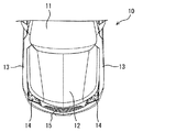
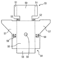
先ず、図1及び図2に基づき、本実施形態の電子制御装置20の搭載環境の一例について説明する。図1に示すように、車両10は、フロントウインドシールド11よりも前方に、ボンネット12を有している。ボンネット12は、フードとも称される。車両の左右方向において、ボンネット12の両サイドには、図示しないタイヤや、タイヤによる石、泥、水などのはねから乗員を保護するために、フロントフェンダ13が取り付けられている。また、車両10の前方には、左右両側にヘッドライト14が設けられている。ヘッドライト14の間には、外部から空気を取り入れるためのフロントグリル15が設けられている。
First, based on FIG.1 and FIG.2, an example of the mounting environment of the electronic control apparatus 20 of this embodiment is demonstrated. As shown in FIG. 1, the vehicle 10 has a hood 12 in front of the front windshield 11. The bonnet 12 is also referred to as a hood. A front fender 13 is attached to both sides of the bonnet 12 in the left-right direction of the vehicle in order to protect the occupant from unillustrated tires and splashes of stones, mud, water and the like. Further, headlights 14 are provided in front of the vehicle 10 on both the left and right sides. A front grille 15 is provided between the headlights 14 for taking in air from the outside.
図2に示すように、隔壁16により、乗員が搭乗する車室内(キャビン)と隔てられたボンネット12の下のエンジンコンパートメント17には、エンジン18や車両補機などが配置されている。エンジンコンパートメント17は、エンジンルームとも称される。エンジンコンパートメント17は区画室、ボンネット12は区画室上の蓋とも言える。エンジンコンパートメント17は、フロントフェンダ13、フロントグリル15、及び隔壁16などによって区画形成されている。
As shown in FIG. 2, an engine 18, a vehicle auxiliary machine, and the like are arranged in an engine compartment 17 below the hood 12 that is separated from a passenger compartment (cabin) in which an occupant is boarded by a partition wall 16. The engine compartment 17 is also referred to as an engine room. It can be said that the engine compartment 17 is a compartment and the bonnet 12 is a lid on the compartment. The engine compartment 17 is defined by a front fender 13, a front grill 15, a partition wall 16, and the like.
エンジンコンパートメント17には、エンジン18以外にも、バッテリ19、電子制御装置20、及びリレーボックス21などが配置されている。電子制御装置20は、エンジンECU(Electric Control Unit)として構成されている。バッテリ19は、箱状部材とも言える。電子制御装置20は、エンジン18が出力すべき目標トルクの算出などを実行する。また、電子制御装置20は、エンジン18が要求される目標トルクを生じるために、ワイヤハーネス22を通じて、スロットルバルブの開度、燃料噴射量、及び点火タイミングなどを制御する。
In addition to the engine 18, the engine compartment 17 includes a battery 19, an electronic control unit 20, a relay box 21, and the like. The electronic control unit 20 is configured as an engine ECU (Electric Control Unit). The battery 19 can also be said to be a box-shaped member. The electronic control unit 20 executes calculation of a target torque that the engine 18 should output. Further, the electronic control unit 20 controls the opening degree of the throttle valve, the fuel injection amount, the ignition timing, and the like through the wire harness 22 in order to generate the target torque required by the engine 18.
リレーボックス21は、車内の電装品に対してバッテリ19の電力を分配するために、多数のリレーやヒューズなどを備えて構成されている。このリレーボックス21には、ワイヤハーネス23の一部を通じて、電子制御装置20へ電力を供給したり、電子制御装置20から制御信号が入力されたりする。電子制御装置20は、この制御信号により、車両10に搭載された電装品への電力の供給を制御する。また、ワイヤハーネス23の残りは、隔壁16に設けられた貫通孔16aを通じて、図示しないボディ系の各種ECU、メータ、各種スイッチなどに接続されている。これにより、電子制御装置20とボディの各種ECUや制御対象との間で信号のやりとりが可能となっている。なお、ワイヤハーネス22とワイヤハーネス23は、互いを区別するために、ワイヤハーネス22をエンジン側ハーネスと称し、ワイヤハーネス23をリレー側ハーネスと称することができる。
The relay box 21 includes a large number of relays and fuses in order to distribute the power of the battery 19 to the electrical components in the vehicle. The relay box 21 is supplied with electric power to the electronic control device 20 through a part of the wire harness 23 or a control signal is input from the electronic control device 20. The electronic control unit 20 controls the supply of electric power to the electrical components mounted on the vehicle 10 by this control signal. The remainder of the wire harness 23 is connected to various body-type ECUs, meters, various switches, and the like (not shown) through through holes 16 a provided in the partition wall 16. As a result, signals can be exchanged between the electronic control unit 20 and the various ECUs and controlled objects of the body. In order to distinguish the wire harness 22 and the wire harness 23 from each other, the wire harness 22 can be referred to as an engine-side harness, and the wire harness 23 can be referred to as a relay-side harness.
次に、図3〜図16に基づき、バッテリ19及び該バッテリ19の隣に配置される電子制御装置20について説明する。
Next, the battery 19 and the electronic control device 20 arranged next to the battery 19 will be described with reference to FIGS.
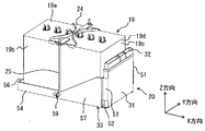
バッテリ19は、各種の電気機器、電子機器の制御を行うために充放電する。図3及び図4に示すように、バッテリ19は、略直方体形状をなしており、外表面として、図示しない端子などが形成された上面19aと、側面である長側面19b及び短側面19cと、上面19aと反対の図示しない底面と、を有している。長側面19bは、略長方形をなす上面19aの長辺に連結された側面であり、短側面19cは、上面19aの短辺に連結された側面である。一対の長側面19b及び一対の短側面19cは、いずれもほぼ全面が平坦な面、すなわち平面部19dとなっている。バッテリ19は、後述するブラケット33のトレイ部54を構成する底板部55上に配置されている。
The battery 19 is charged and discharged in order to control various electric devices and electronic devices. As shown in FIGS. 3 and 4, the battery 19 has a substantially rectangular parallelepiped shape, and as an outer surface, an upper surface 19 a on which terminals and the like (not shown) are formed, a long side surface 19 b and a short side surface 19 c which are side surfaces, And a bottom surface (not shown) opposite to the top surface 19a. The long side surface 19b is a side surface connected to the long side of the upper surface 19a having a substantially rectangular shape, and the short side surface 19c is a side surface connected to the short side of the upper surface 19a. The pair of long side surfaces 19b and the pair of short side surfaces 19c are both substantially flat surfaces, that is, flat portions 19d. The battery 19 is disposed on a bottom plate portion 55 that constitutes a tray portion 54 of the bracket 33 described later.
バッテリ19は、トレイ部54、ひいては車両10に固定されている。バッテリ19の上面19aには、バッテリ19をクランプするクランプ部材24が配置されている。クランプ部材24は、長辺の中央付近において短辺方向に沿って上面19aを跨ぐように配置されている。図3及び図5などに示すように、クランプ部材24の両端は、上面19aよりも外側に延設されている。クランプ部材24の両端には、J型のフック部材25が連結されている。フック部材25において、クランプ部材24との連結端と反対の下端部は、J字状に屈曲されている。上記したトレイ部54を構成する横板部56,57のうち、バッテリ19の長側面19bに対向配置された横板部57に掛け止め部59が形成されており、この掛け止め部59にフック部材25の下端部が掛け止めされている。このように、バッテリ19は、底板部55とクランプ部材24によって挟持されている。
The battery 19 is fixed to the tray portion 54 and eventually the vehicle 10. A clamp member 24 that clamps the battery 19 is disposed on the upper surface 19 a of the battery 19. The clamp member 24 is disposed so as to straddle the upper surface 19a along the short side direction in the vicinity of the center of the long side. As shown in FIGS. 3 and 5, both ends of the clamp member 24 are extended outward from the upper surface 19 a. J-shaped hook members 25 are connected to both ends of the clamp member 24. In the hook member 25, the lower end portion opposite to the connection end with the clamp member 24 is bent in a J-shape. Of the horizontal plate portions 56 and 57 constituting the tray portion 54 described above, a latching portion 59 is formed on the horizontal plate portion 57 disposed opposite to the long side surface 19b of the battery 19, and a hook is attached to the latching portion 59. The lower end portion of the member 25 is latched. As described above, the battery 19 is sandwiched between the bottom plate portion 55 and the clamp member 24.
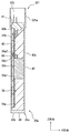
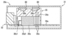
電子制御装置20は、図12などに示すように、第1回路基板30aと、第2回路基板30bと、筐体31と、コネクタ32とを有している。第1回路基板30aや第2回路基板30bは、電子部品が実装されている。第1回路基板30aに実装された電子部品は、回路素子30cを含むものである。つまり、電子制御装置20は、上記構成要素30a,30b,31,32に加えて、回路素子30cを備えていると言える。さらに、本実施形態では、筐体31内にポッティング材70が充填された電子制御装置20を採用している。なお、以下においては、第1回路基板30aと第2回路基板30bとを区別する必要がない場合、回路基板30a,30bとも記載する。
As shown in FIG. 12 and the like, the electronic control unit 20 includes a first circuit board 30a, a second circuit board 30b, a housing 31, and a connector 32. Electronic components are mounted on the first circuit board 30a and the second circuit board 30b. The electronic component mounted on the first circuit board 30a includes a circuit element 30c. That is, it can be said that the electronic control unit 20 includes the circuit element 30c in addition to the above-described components 30a, 30b, 31, and 32. Further, in this embodiment, the electronic control device 20 in which the potting material 70 is filled in the casing 31 is employed. In the following, when it is not necessary to distinguish the first circuit board 30a and the second circuit board 30b, they are also referred to as circuit boards 30a and 30b.
回路基板30a,30bは、絶縁基材に導体パターンなどが形成されたものである。回路基板30a,30bとしては、プリント基板やセラミック基板を採用できる。また、第1回路基板30aと第2回路基板30bは、例えば平板形状の基板である。
The circuit boards 30a and 30b are obtained by forming a conductor pattern or the like on an insulating base material. As the circuit boards 30a and 30b, a printed board or a ceramic board can be adopted. Further, the first circuit board 30a and the second circuit board 30b are, for example, flat-plate-shaped boards.
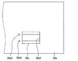
第1回路基板30aは、図12、図13、及び図14に示すように、位置決め穴30a1やスルーホール30a2が形成されている。なお、図13では、筐体31やポッティング材70などを省略している。
As shown in FIGS. 12, 13, and 14, the first circuit board 30a has a positioning hole 30a1 and a through hole 30a2. In FIG. 13, the casing 31, the potting material 70, and the like are omitted.
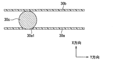
位置決め穴30a1は、特許請求の範囲における第1穴部に相当する。位置決め穴30a1は、絶縁基材の厚み方向に貫通した穴であり、後程説明する回路素子30cの位置を規定するための穴である。言い換えると、位置決め穴30a1は、第1回路基板30aに実装された回路素子30cの位置ずれを抑制するための穴である。また、この位置決め穴30a1は、図12や図13に示すように、回路素子30cの一部が挿入(埋設)される部位である。
The positioning hole 30a1 corresponds to the first hole in the claims. The positioning hole 30a1 is a hole penetrating in the thickness direction of the insulating substrate, and is a hole for defining the position of the circuit element 30c described later. In other words, the positioning hole 30a1 is a hole for suppressing the displacement of the circuit element 30c mounted on the first circuit board 30a. Further, the positioning hole 30a1 is a part into which a part of the circuit element 30c is inserted (embedded) as shown in FIGS.
さらに、位置決め穴30a1は、回路素子30cの一部が挿入(埋設)されることで、回路素子30cの位置ずれを抑制する。このために、位置決め穴30a1は、図14、図15に示すように、回路素子30cにおける胴体部の直径よりも、幅が狭い穴となっている。なお、位置決め穴30a1の長さは、図14に示すように、回路素子30cにおける胴体部の長さと同等である。
Further, the positioning hole 30a1 suppresses the positional deviation of the circuit element 30c by inserting (embedding) a part of the circuit element 30c. For this reason, as shown in FIGS. 14 and 15, the positioning hole 30a1 is a hole whose width is narrower than the diameter of the body portion of the circuit element 30c. In addition, the length of the positioning hole 30a1 is equivalent to the length of the trunk | drum part in the circuit element 30c, as shown in FIG.
スルーホール30a2は、絶縁基材の厚み方向に貫通した穴であり、回路素子30cの端子である素子側端子30c1が挿入される穴である。スルーホール30a2は、絶縁基材の厚み方向に貫通した穴の表面に、銅めっきなどの導電性部材が形成されている。スルーホール30a2は、自身に挿入された素子側端子30c1と、はんだ60によって電気的及び機械的に接続される。素子側端子30c1とはんだ60は、第1回路基板30aと回路素子30cとの接続部とも言える。
The through hole 30a2 is a hole that penetrates in the thickness direction of the insulating base material, and is a hole into which the element side terminal 30c1 that is a terminal of the circuit element 30c is inserted. In the through hole 30a2, a conductive member such as copper plating is formed on the surface of the hole penetrating in the thickness direction of the insulating base material. The through hole 30a2 is electrically and mechanically connected to the element side terminal 30c1 inserted therein by the solder 60. The element-side terminal 30c1 and the solder 60 can be said to be a connection portion between the first circuit board 30a and the circuit element 30c.
なお、本実施形態では、素子側端子30c1がスルーホール30a2に挿入されて、素子側端子30c1と第1回路基板30aとが電気的及び機械的に接続されている。しかしながら、本発明はこれに限定されない。後程説明するが、本発明は、表面実装構造の回路素子30hでも採用できる。
In the present embodiment, the element side terminal 30c1 is inserted into the through hole 30a2, and the element side terminal 30c1 and the first circuit board 30a are electrically and mechanically connected. However, the present invention is not limited to this. As will be described later, the present invention can also be applied to the circuit element 30h having a surface mounting structure.
一方、第2回路基板30bは、第1回路基板30aの実装面に対向配置されている。第2回路基板30bは、特許請求の範囲における押さえ部材に相当する。第2回路基板30bは、回路素子30cと一部接触している。そして、第2回路基板30bは、実装面に垂直な方向において、回路素子30cを第1回路基板30aに押し付ける。また、第2回路基板30bは、図示は省略するが、回路素子30cとは異なる電子部品が実装されている。なお、電子制御装置20は、後程説明するが、ポッティング材70で第1回路基板30aに回路素子30cを固定できる。よって、第2回路基板30bは、少なくとも、筐体31内にポッティング材70が注入される際に、回路素子30cを第1回路基板30aに押し付けるものであってもよい。つまり、第2回路基板30bは、筐体31内にポッティング材70が注入される際に、回路素子30cが位置ずれしないようにするための仮押さえ部材と言うこともできる。
On the other hand, the second circuit board 30b is disposed opposite to the mounting surface of the first circuit board 30a. The second circuit board 30b corresponds to a pressing member in the claims. The second circuit board 30b is in partial contact with the circuit element 30c. Then, the second circuit board 30b presses the circuit element 30c against the first circuit board 30a in the direction perpendicular to the mounting surface. Further, although not shown, the second circuit board 30b is mounted with an electronic component different from the circuit element 30c. As will be described later, the electronic control unit 20 can fix the circuit element 30c to the first circuit board 30a with the potting material 70. Therefore, the second circuit board 30b may be one that presses the circuit element 30c against the first circuit board 30a at least when the potting material 70 is injected into the housing 31. That is, the second circuit board 30b can be said to be a temporary holding member for preventing the circuit element 30c from being displaced when the potting material 70 is injected into the housing 31.
第1回路基板30aと第2回路基板30bは、図12などに示すように、筐体31内に収容されており、ポッティング材70により、筐体31に固定されている。なお、第1回路基板30aと第2回路基板30bは、ポッティング材70に加えて、図示しない固定手段により、筐体31に固定されていてもよい。第1回路基板30aと第2回路基板30bには、コネクタ32も実装されている。例えば、第1回路基板30aと第2回路基板30bとは、一つのコネクタ32に固定されることで、互いの間隔を保持できる。なお、コネクタ32に関しては、後程説明する。
As shown in FIG. 12 and the like, the first circuit board 30 a and the second circuit board 30 b are accommodated in the casing 31 and fixed to the casing 31 by a potting material 70. The first circuit board 30a and the second circuit board 30b may be fixed to the casing 31 by a fixing means (not shown) in addition to the potting material 70. A connector 32 is also mounted on the first circuit board 30a and the second circuit board 30b. For example, the first circuit board 30a and the second circuit board 30b can be held at a distance from each other by being fixed to one connector 32. The connector 32 will be described later.
回路素子30cは、特許請求の範囲における電子部品に相当し、一例としてアルミ電解コンデンサを採用する。回路素子30cは、素子側端子30c1を有し、はんだ60を介して素子側端子30c1と第1回路基板30aとが電気的及び機械的に接続され、第1回路基板30aの実装面側に実装されている。はんだ60は、特許請求の範囲における接続部材に相当する。本発明は、はんだ60のかわりに、導電性の接着剤などを採用できる。
The circuit element 30c corresponds to an electronic component in the claims, and an aluminum electrolytic capacitor is adopted as an example. The circuit element 30c has an element-side terminal 30c1, and the element-side terminal 30c1 and the first circuit board 30a are electrically and mechanically connected via the solder 60, and mounted on the mounting surface side of the first circuit board 30a. Has been. The solder 60 corresponds to the connecting member in the claims. In the present invention, a conductive adhesive or the like can be used instead of the solder 60.
回路素子30cは、例えば、図12、図13に示すように、円柱形状の胴体部と、胴体部から突出した二つの素子側端子30c1とを有している。つまり、回路素子30cの胴体部は、筒状部と、筒状部の両端に形成された円形壁部とを含む形状である。そして、回路素子30cは、二つの円形壁部の一方から各素子側端子30c1が突出して形成されている。各素子側端子30c1は、例えば、円形壁部から突出した突出部と、突出部の先端から曲げられた屈曲部とを含み、L字形状をなしていると言える。本実施形態では、平坦な円形壁部と、円形壁部に垂直に設けられた突出部と、突出部の先端に円形壁部に平行に設けられた屈曲部とを含む素子側端子30c1を採用している。このように、本実施形態では、回路素子30cとして、THD(Through Hole Device)のアルミ電解コンデンサを採用している。
For example, as illustrated in FIGS. 12 and 13, the circuit element 30 c includes a cylindrical body portion and two element-side terminals 30 c 1 protruding from the body portion. That is, the body part of the circuit element 30c has a shape including a cylindrical part and circular wall parts formed at both ends of the cylindrical part. The circuit element 30c is formed such that each element-side terminal 30c1 protrudes from one of the two circular wall portions. Each element-side terminal 30c1 includes, for example, a protruding portion protruding from a circular wall portion and a bent portion bent from the tip of the protruding portion, and can be said to be L-shaped. In the present embodiment, the element-side terminal 30c1 including a flat circular wall portion, a protruding portion provided perpendicular to the circular wall portion, and a bent portion provided in parallel to the circular wall portion at the tip of the protruding portion is employed. doing. Thus, in this embodiment, a THD (Through Hole Device) aluminum electrolytic capacitor is employed as the circuit element 30c.
回路素子30cは、筒状部が実装面と平行で、円形壁部が実装面と垂直となるように第1回路基板30aに配置されている。また、回路素子30cは、屈曲部が第1回路基板30aのスルーホール30a2に挿入された状態で、第1回路基板30aに実装されている。また、回路素子30cは、自身の長手方向が実装面と平行となり、自身の短手方向が実装面と垂直になるように、第1回路基板30aに実装されているため、横置き実装されていると言うこともできる。
The circuit element 30c is disposed on the first circuit board 30a so that the cylindrical portion is parallel to the mounting surface and the circular wall portion is perpendicular to the mounting surface. The circuit element 30c is mounted on the first circuit board 30a in a state where the bent portion is inserted into the through hole 30a2 of the first circuit board 30a. The circuit element 30c is mounted on the first circuit board 30a so that its own longitudinal direction is parallel to the mounting surface and its short direction is perpendicular to the mounting surface. You can also say.
さらに、回路素子30cは、図12、図13、図15自身の一部のみが位置決め穴30a1内に配置されている。詳述すると、回路素子30cは、図12、図13に示すように、胴体部の高さ方向の一部及び胴体部の長さ方向の全体のみが位置決め穴30a1内に配置されると言える。また、上記のように、回路素子30cは、第2回路基板30bから第1回路基板30aに押し付けられているため、第1回路基板30aと第2回路基板30bとで挟み込まれた状態で筐体31内に収容されていると言える。
Further, only part of the circuit element 30c of FIGS. 12, 13, and 15 itself is disposed in the positioning hole 30a1. More specifically, as shown in FIGS. 12 and 13, in the circuit element 30c, it can be said that only a part of the body portion in the height direction and the whole body portion in the length direction are disposed in the positioning hole 30a1. Further, as described above, since the circuit element 30c is pressed from the second circuit board 30b to the first circuit board 30a, the casing is held between the first circuit board 30a and the second circuit board 30b. It can be said that it is accommodated in 31.
電子制御装置20は、回路素子30cが位置決め穴30a1内に配置されているため、回路素子30cが横方向(Y方向)に位置ずれすることを抑制できる。また、電子制御装置20は、回路素子30cが位置決め穴30a1内に配置され、スルーホール30a2に素子側端子30c1が挿入されてはんだ60で固定されているため、回路素子30cが縦方向(Z方向)に位置ずれすることを抑制できる。さらに、電子制御装置20は、回路素子30cが第2回路基板30bから第1回路基板30aに押し付けられているため、回路素子30cが高さ方向(X方向)に位置ずれすることを抑制できる。このように、電子制御装置20は、回路素子30cが横方向、縦方向、高さ方向の3方向に位置ずれすることを抑制できる。
The electronic control device 20 can suppress the circuit element 30c from being displaced in the lateral direction (Y direction) because the circuit element 30c is disposed in the positioning hole 30a1. Further, in the electronic control unit 20, since the circuit element 30c is disposed in the positioning hole 30a1, and the element side terminal 30c1 is inserted into the through hole 30a2 and fixed by the solder 60, the circuit element 30c is in the vertical direction (Z direction). ) Can be suppressed. Furthermore, since the circuit element 30c is pressed against the first circuit board 30a from the second circuit board 30b, the electronic control unit 20 can suppress the circuit element 30c from being displaced in the height direction (X direction). As described above, the electronic control unit 20 can suppress the displacement of the circuit element 30c in the three directions of the horizontal direction, the vertical direction, and the height direction.
筐体31は、金属材料を用いて形成されている。これにより、筐体31は、回路基板30a,30bが発した熱を筐体31の外部に放熱する機能を果たす。筐体31は、図12に示すように、袋形状をなしており、自身の深さ方向であるZ方向の一端側に底部40を有し、底部40と反対の他端側に開口部41を有している。また、筐体31は、底部40に連結され、底部40とともに回路基板30a,30bなどを収容する空間を形成する側壁部42を有している。つまり、側壁部42は、環状に設けられている。なお、底部40は、側壁部42とともに筐体31の壁部の一部をなすものであるため、底壁部40と言うこともできる。
The casing 31 is formed using a metal material. As a result, the housing 31 functions to dissipate heat generated by the circuit boards 30 a and 30 b to the outside of the housing 31. As shown in FIG. 12, the housing 31 has a bag shape, and has a bottom 40 on one end side in the Z direction that is the depth direction of the housing 31, and an opening 41 on the other end opposite to the bottom 40. have. The casing 31 has a side wall portion 42 that is connected to the bottom portion 40 and forms a space for accommodating the circuit boards 30a, 30b and the like together with the bottom portion 40. That is, the side wall part 42 is provided in an annular shape. In addition, since the bottom part 40 forms a part of wall part of the housing | casing 31 with the side wall part 42, it can also be called the bottom wall part 40. FIG.
上記のように、ポッティング材70は、筐体31内に設けられている。このポッティング材70は、特許請求の範囲における封止樹脂に相当する。そして、ポッティング材70は、第1回路基板30a及び回路素子30cを覆い、第1回路基板30aに回路素子30cを固定している。さらに、ポッティング材70は、第2回路基板30bを覆い、第1回路基板30a及び回路素子30cに対して、第2回路基板30bを固定している。このように、ポッティング材70は、筐体31内を一体的に封止して、筐体31内に配置された構成要素を固定していると言える。
As described above, the potting material 70 is provided in the housing 31. The potting material 70 corresponds to the sealing resin in the claims. The potting material 70 covers the first circuit board 30a and the circuit element 30c, and fixes the circuit element 30c to the first circuit board 30a. Further, the potting material 70 covers the second circuit board 30b, and fixes the second circuit board 30b to the first circuit board 30a and the circuit element 30c. Thus, it can be said that the potting material 70 integrally seals the inside of the housing 31 and fixes the components arranged in the housing 31.
このような袋形状をなす筐体31は、単一部材により構成することもできるし、複数の部材を組み付けることで構成することもできる。本実施形態では、パンチを用いたインパクト加工法を採用することで、筐体31が単一部材で構成されている。インパクト加工法を採用すると、アルミダイカスト法を用いた単一部材や複数部材の組み付けに較べて、筐体31のX方向の長さ、すなわち厚みを薄くすることができる。
The casing 31 having such a bag shape can be configured by a single member or can be configured by assembling a plurality of members. In this embodiment, the housing | casing 31 is comprised with the single member by employ | adopting the impact processing method using a punch. When the impact processing method is employed, the length in the X direction, that is, the thickness of the housing 31 can be reduced as compared with the assembly of a single member or a plurality of members using the aluminum die casting method.
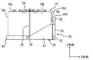
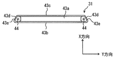
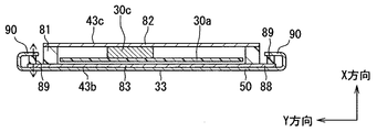
筐体31は、図9、図10、図11及び図12に示すように、その外表面として、底部40の外面である底面43aと、バッテリ19の平面部19dに対向配置される対向面43bと、対向面43bと反対の裏面43cと、対向面43b及び裏面43cにおけるY方向の両端をそれぞれ連結する一対の連結面43dと、有している。そして、一対の連結面43dが、Z方向の少なくとも一部であってX方向の所定範囲に、裏面43cに近づくほどY方向における一対の連結面43dの間隔が狭くなるように傾斜した斜面部43eをそれぞれ有している。一対の斜面部43eは、対向面43bから裏面43cに近づくにつれて、互いの間隔が徐々に短くなるように傾斜していると言うこともできる。一対の斜面部43eは、互いに対向するように設けられている。なお、一対の連結面43dの間隔とは、一方の連結面43dから他方の連結面43dまでのY方向の距離である。
As shown in FIGS. 9, 10, 11, and 12, the housing 31 has, as its outer surface, a bottom surface 43 a that is an outer surface of the bottom portion 40 and a facing surface 43 b that is disposed to face the flat portion 19 d of the battery 19. And a back surface 43c opposite to the facing surface 43b, and a pair of connecting surfaces 43d that connect both ends of the facing surface 43b and the back surface 43c in the Y direction. The pair of connecting surfaces 43d is at least part of the Z direction and is inclined to the predetermined range in the X direction so that the distance between the pair of connecting surfaces 43d in the Y direction becomes narrower as the back surface 43c is approached. Respectively. It can also be said that the pair of inclined surface portions 43e are inclined so that the interval between the pair of inclined surface portions 43e gradually decreases from the opposing surface 43b to the back surface 43c. The pair of slope portions 43e are provided to face each other. The interval between the pair of connecting surfaces 43d is a distance in the Y direction from one connecting surface 43d to the other connecting surface 43d.
本実施形態では、対向面43b及び裏面43cがほぼ平坦な面となっている。そして、連結面43dは、対向面43b及び裏面43cとの連結部分である屈曲部を除いて、斜面部43eとなっている。すなわち、連結面43dのほぼ全面が斜面部43eとなっている。連結面43dと対向面43bとのなす角度は鋭角とされ、連結面43dと裏面43cとのなす角度は鈍角となっている。このため、図10に示すように、Z方向からみて、筐体31は略台形状をなしている。したがって、Y方向において、一対の連結面43dの間に裏面43cが位置している。また、底部40には、図9に示すように、底面43aに開口する所定深さのねじ穴44が形成されている。
In the present embodiment, the opposing surface 43b and the back surface 43c are substantially flat surfaces. And the connection surface 43d becomes the slope part 43e except the bending part which is a connection part with the opposing surface 43b and the back surface 43c. That is, almost the entire connection surface 43d is a slope portion 43e. The angle formed by the connecting surface 43d and the opposing surface 43b is an acute angle, and the angle formed by the connecting surface 43d and the back surface 43c is an obtuse angle. For this reason, as shown in FIG. 10, the housing 31 has a substantially trapezoidal shape when viewed from the Z direction. Therefore, the back surface 43c is located between the pair of connecting surfaces 43d in the Y direction. Further, as shown in FIG. 9, a screw hole 44 having a predetermined depth that opens to the bottom surface 43a is formed in the bottom portion 40.
このように構成される筐体31は、図3及び図4に示すように、バッテリ19における一方の短側面19cの隣(横)に配置されている。詳述すると、筐体31は、短側面19cに対し、対向面43bが対向配置されている。筐体31は、開口部41が底部40に対して上方となるように、短側面19c(平面部19d)の横に配置されている。すなわち、コネクタ32が、底部40に対して上方となるように配置されている。なお、Z方向が車両10における上下方向に略一致する。上方とは、車両上方である。
As shown in FIGS. 3 and 4, the casing 31 configured in this manner is disposed next to (beside) one short side surface 19 c of the battery 19. More specifically, the housing 31 has a facing surface 43b opposed to the short side surface 19c. The housing 31 is disposed beside the short side surface 19c (plane portion 19d) so that the opening 41 is located above the bottom portion 40. That is, the connector 32 is disposed so as to be above the bottom portion 40. Note that the Z direction substantially coincides with the vertical direction of the vehicle 10. The upper side is the upper side of the vehicle.
コネクタ32は、第1回路基板30aと第2回路基板30bに実装されており、第1回路基板30a及び第2回路基板30bと外部機器とを電気的に中継する。コネクタ32の一部は、図9などに示すように、筐体31に収容され、残りの部分は、筐体31から外部に露出されている。コネクタ32には、外部機器側のコネクタ(メスコネクタ)が嵌合され、コネクタ32及びメスコネクタを介して、回路基板30a,30bなどが上記したワイヤハーネス22,23と電気的に接続される。例えば、電子制御装置20は、コネクタ32、メスコネクタ、及びワイヤハーネス22を介して、回路基板30a,30bとエンジン18とが電気的に接続されている。また、電子制御装置20は、コネクタ32、メスコネクタ、及びワイヤハーネス23を介して、回路基板30a,30bとリレーボックス21などが電気的に接続されている。
The connector 32 is mounted on the first circuit board 30a and the second circuit board 30b, and electrically relays the first circuit board 30a and the second circuit board 30b and an external device. As shown in FIG. 9 and the like, a part of the connector 32 is accommodated in the housing 31 and the remaining part is exposed from the housing 31 to the outside. The connector 32 is fitted with a connector (female connector) on the external device side, and the circuit boards 30a, 30b and the like are electrically connected to the wire harnesses 22, 23 via the connector 32 and the female connector. For example, in the electronic control device 20, the circuit boards 30 a and 30 b and the engine 18 are electrically connected via the connector 32, the female connector, and the wire harness 22. In the electronic control device 20, the circuit boards 30 a and 30 b and the relay box 21 are electrically connected via the connector 32, the female connector, and the wire harness 23.
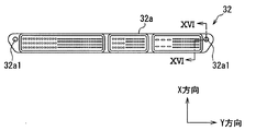
コネクタ32は、図9、図11、図16などに示すように、樹脂などの電気絶縁性材料を用いて形成されたハウジング32aと、導電性材料を用いて形成され、ハウジング32aに保持された複数の第1端子32bと複数の第2端子32cと、を有している。複数の第1端子32bは、例えば、ハウジング32aに対してY方向に配列されるとともに、X方向に多段に配置されている。複数の第2端子32cに関しても同様である。なお、段数は、特に限定されない。第1端子32bは、第1回路基板30aに電気的及び機械的に接続されている。一方、第2端子32cは、第2回路基板30bに電気的及び機械的に接続されている。
As shown in FIG. 9, FIG. 11, FIG. 16, etc., the connector 32 is formed by using a housing 32a formed of an electrically insulating material such as a resin and a conductive material, and is held by the housing 32a. A plurality of first terminals 32b and a plurality of second terminals 32c are provided. For example, the plurality of first terminals 32b are arranged in the Y direction with respect to the housing 32a and are arranged in multiple stages in the X direction. The same applies to the plurality of second terminals 32c. The number of stages is not particularly limited. The first terminal 32b is electrically and mechanically connected to the first circuit board 30a. On the other hand, the second terminal 32c is electrically and mechanically connected to the second circuit board 30b.
コネクタ32は、筐体31の開口部41及びその周辺に配置され、開口部41を閉塞している。ハウジング32aと筐体31とは、開口部41の周辺において嵌合している。また、ハウジング32aと側壁部42における開口部41の周囲部分との間には、図示しない防水用のシール材が配置されている。これにより、電子制御装置20は、筐体31の内部空間が防水空間となっている。図12では、第1端子32bが第1回路基板30aに対して挿入実装されており、第2端子32cが第2回路基板30bに対して挿入実装されているが、表面実装構造を採用することもできる。
The connector 32 is disposed at and around the opening 41 of the housing 31 and closes the opening 41. The housing 32 a and the housing 31 are fitted around the opening 41. Further, a waterproof sealing material (not shown) is disposed between the housing 32a and the peripheral portion of the opening portion 41 in the side wall portion. Thereby, as for the electronic control apparatus 20, the internal space of the housing | casing 31 is waterproofing space. In FIG. 12, the first terminal 32b is inserted and mounted on the first circuit board 30a, and the second terminal 32c is inserted and mounted on the second circuit board 30b, but a surface mounting structure is adopted. You can also.
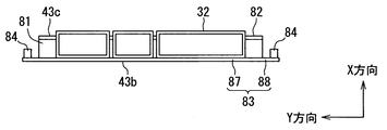
図3、図7、図9、及び図11などに示すように、コネクタ32のハウジング32aは3つのポート(言い換えると、嵌合口)を有している。コネクタ32は、3つのポートの一部が、エンジン18を駆動させるためのワイヤハーネス22との接続に供せられるエンジンブロックとされている。また、コネクタ32は、残りのポートが、リレーボックス21及びボディECUに対応するワイヤハーネス23との接続に供せられるボディブロックとされている。そして、コネクタ32は、図2に示した配置において、エンジンブロックがエンジン18に近い側、ボディブロックがリレーボックス21や貫通孔16aに近い側となるように、ワイヤハーネス22,23の配索を考慮して、各ブロックの配置が決定されている。なお、コネクタ32のポート数は特に限定されない。
As shown in FIGS. 3, 7, 9, and 11, the housing 32a of the connector 32 has three ports (in other words, fitting ports). The connector 32 is an engine block in which a part of the three ports is provided for connection to the wire harness 22 for driving the engine 18. The connector 32 is a body block whose remaining ports are used for connection to the relay box 21 and the wire harness 23 corresponding to the body ECU. In the arrangement shown in FIG. 2, the wiring harnesses 22, 23 are arranged so that the engine block is closer to the engine 18 and the body block is closer to the relay box 21 and the through hole 16 a in the arrangement shown in FIG. 2. Considering this, the arrangement of each block is determined. Note that the number of ports of the connector 32 is not particularly limited.
さらに、図6、図11、図16に示すように、ハウジング32aは、筐体31内にポッティング材70を注入するための注入口32a1が設けられている。つまり、ハウジング32aは、自身の厚み方向(Z方向)に貫通した注入口32a1が設けられている。そして、電子制御装置20は、筐体31の開口部41をコネクタ32で閉塞した状態で、注入口32a1から筐体31内にポッティング材70が注入される。例えば、電子制御装置20は、注入口32a1が底部40よりも上方に配置された状態で、注入口32a1からポッティング材70を注入する。
Further, as shown in FIGS. 6, 11, and 16, the housing 32 a is provided with an inlet 32 a 1 for injecting the potting material 70 into the housing 31. That is, the housing 32a is provided with an injection port 32a1 penetrating in its thickness direction (Z direction). In the electronic control device 20, the potting material 70 is injected into the housing 31 from the injection port 32 a 1 with the opening 41 of the housing 31 closed by the connector 32. For example, the electronic control device 20 injects the potting material 70 from the injection port 32a1 in a state where the injection port 32a1 is disposed above the bottom portion 40.
電子制御装置20は、ブラケット33に固定されている。このブラケット33は、回路基板30a,30bが収容された筐体31を、車両10に取り付けるための部材である。言い換えると、ブラケット33は、電子制御装置20を車両に取り付けための部材である。つまり、電子制御装置20は、ブラケット33を介して車両10に取り付けられている。また、電子制御装置20は、自身の熱を筐体31からブラケット33に放熱するために、筐体31とブラケット33との間に伝熱部材が設けられていてもよい。
The electronic control unit 20 is fixed to the bracket 33. The bracket 33 is a member for attaching the housing 31 in which the circuit boards 30 a and 30 b are accommodated to the vehicle 10. In other words, the bracket 33 is a member for attaching the electronic control device 20 to the vehicle. That is, the electronic control device 20 is attached to the vehicle 10 via the bracket 33. Further, the electronic control device 20 may be provided with a heat transfer member between the housing 31 and the bracket 33 in order to dissipate its own heat from the housing 31 to the bracket 33.
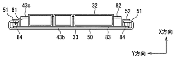
ブラケット33は、金属製の介在部50と、金属製の一対の板ばね部51を少なくとも有している。一対の板ばね部51が、一対の折り返し部に相当する。
The bracket 33 has at least a metal interposition part 50 and a pair of metal leaf spring parts 51. The pair of leaf spring portions 51 corresponds to a pair of folded portions.
介在部50は、バッテリ19の平面部19d(短側面19c)と筐体31の対向面43bとの間に介在する。介在部50は、一対の板ばね部51を連結するものであるため、連結部と称することもできる。また、介在部50は、自身のY方向両端に板ばね部51がそれぞれ連結されているため、基部(ベース)と称することもできる。
The interposition part 50 is interposed between the flat part 19 d (short side surface 19 c) of the battery 19 and the facing surface 43 b of the housing 31. Since the interposition part 50 connects a pair of leaf | plate spring parts 51, it can also be called a connection part. Moreover, since the leaf | plate spring part 51 is each connected to the Y direction both ends, the interposition part 50 can also be called a base (base).
板ばね部51は、介在部50のY方向両端からX方向において裏面43c側に延びるとともに、X方向において介在部50と対向するように、介在部50に対して折り返されている。このように折り返された板ばね部51は、X方向にばね変形可能となっている。一対の板ばね部51は、上記折り返し構造により、一対の連結面43dの斜面部43eにそれぞれ接触して、対応する斜面部43eにばね変形による反力を付与する。ばね変形は、弾性変形とも称される。斜面部43eは、ブラケット33の板ばね部51が接触する部分であり、その接触位置は、X方向において、裏面43cと対向面43bの間の位置とされる。したがって、斜面部43eは、筐体31のうち、板ばね部51を受ける受け部に相当する。
The leaf spring portion 51 extends from the both ends of the interposition portion 50 in the Y direction toward the back surface 43c in the X direction, and is folded back with respect to the interposition portion 50 so as to face the interposition portion 50 in the X direction. The leaf spring portion 51 folded back in this way can be spring-deformed in the X direction. A pair of leaf | plate spring part 51 respectively contacts the slope part 43e of a pair of connection surface 43d by the said folding structure, and provides the reaction force by a spring deformation | transformation to the corresponding slope part 43e. Spring deformation is also referred to as elastic deformation. The slope portion 43e is a portion where the leaf spring portion 51 of the bracket 33 contacts, and the contact position is a position between the back surface 43c and the facing surface 43b in the X direction. Therefore, the inclined surface portion 43 e corresponds to a receiving portion that receives the leaf spring portion 51 in the housing 31.
板ばね部51と介在部50との連結方法は特に限定されない。介在部50と板ばね部51とを別部材で構成し、たとえば溶接により連結してもよい。本実施形態では、図8に示すように、平板状の金属板を所定形状に加工することで、ブラケット33が構成される。すなわち、板ばね部51と介在部50とが、同一金属板の一部同士として一体的に連結されている。図8では、介在部50と板ばね部51との境界(連結部分)を破線で示している。また、その他の境界についても破線で示している。
The connection method of the leaf | plate spring part 51 and the interposition part 50 is not specifically limited. The interposition part 50 and the leaf | plate spring part 51 may be comprised by another member, and may be connected by welding, for example. In this embodiment, as shown in FIG. 8, the bracket 33 is formed by processing a flat metal plate into a predetermined shape. That is, the leaf | plate spring part 51 and the interposition part 50 are integrally connected as a part of the same metal plate. In FIG. 8, the boundary (connection part) between the interposition part 50 and the leaf | plate spring part 51 is shown with the broken line. The other boundaries are also indicated by broken lines.
板ばね部51は、介在部50のY方向両端にそれぞれ設けられており、介在部50に対してバッテリ19とは反対側に折曲されている。詳述すると、板ばね部51は、筐体31の斜面部43eに接触するように、介在部50とのなす角度が鋭角となっている。板ばね部51は、介在部50との連結端に屈曲部(折曲部)を有しており、これにより対応する斜面部43eに接触するとともに、該斜面部43eにばね変形による反力を付与することができる。つまり、板ばね部51は、斜面部43eを押圧できるように、介在部50に対して屈曲されている。一対の斜面部43eは、一対の板ばね部51によって押圧されている。このため、筐体31は、板ばね部51によって固定されている。言い換えると、電子制御装置20は、斜面部43eが板ばね部51によって押圧されることで、ブラケット33に保持(固定)されている。なお、板ばね部51は、固定部51と称することもできる。
The leaf spring portions 51 are provided at both ends of the interposition portion 50 in the Y direction, and are bent to the opposite side of the interposition portion 50 from the battery 19. Specifically, the leaf spring portion 51 has an acute angle with the interposition portion 50 so as to contact the slope portion 43e of the housing 31. The leaf spring portion 51 has a bent portion (bent portion) at the connection end with the interposition portion 50, thereby contacting the corresponding slope portion 43 e and applying a reaction force due to spring deformation to the slope portion 43 e. Can be granted. That is, the leaf spring portion 51 is bent with respect to the interposition portion 50 so as to press the slope portion 43e. The pair of slope portions 43 e is pressed by the pair of leaf spring portions 51. For this reason, the housing 31 is fixed by the leaf spring portion 51. In other words, the electronic control device 20 is held (fixed) to the bracket 33 by the inclined surface portion 43e being pressed by the leaf spring portion 51. The leaf spring portion 51 can also be referred to as a fixed portion 51.
本実施形態では、図3及び図4などに示すように、板ばね部51が、Z方向において、介在部50の一部のみに連結されている。詳しくは、Z方向において、介在部50の上端から下端までのうち、上端から所定範囲の部分にのみ板ばね部51が連結され、下端から上方への一部の範囲には連結されていない。しかしながら、介在部50の上端から下端に亘って、板ばね部51が連結される構成としてもよい。板ばね部51の介在部50に対する曲げ角度は、Z方向においてほぼ一定となっている。
In the present embodiment, as shown in FIGS. 3 and 4, the leaf spring portion 51 is connected to only a part of the interposition portion 50 in the Z direction. Specifically, in the Z direction, the leaf spring portion 51 is connected only to a portion within a predetermined range from the upper end of the interposition portion 50 from the upper end to the lower end, and is not connected to a partial range upward from the lower end. However, the leaf spring portion 51 may be connected from the upper end to the lower end of the interposition portion 50. The bending angle of the leaf spring part 51 with respect to the interposition part 50 is substantially constant in the Z direction.
また、ブラケット33は、板ばね部51における斜面部43eとの対向部分にたとえば突起を設け、この突起が斜面部43eに接触する構成とすることもできる。これによれば、板ばね部51と斜面部43eとの接触面積を減らし、ブラケット33に対して、回路基板30a,30b及びコネクタ32を含む筐体31を取り付けやすくすることができる。なお、筐体31とブラケット33とを固定する際には、筐体31には回路基板30a,30bが収容されており、回路基板30a,30bにはコネクタ32が実装されている。したがって、厳密には、回路基板30a,30b及びコネクタ32を含む筐体31と、ブラケット33とを固定する。しかしながら、以下においては、単に、筐体31とブラケット33とを固定すると示す。また、電子制御装置20とブラケット33とを固定するとも言える。
Further, the bracket 33 may be configured such that, for example, a protrusion is provided on a portion of the leaf spring portion 51 facing the slope portion 43e, and the protrusion comes into contact with the slope portion 43e. According to this, the contact area between the leaf spring portion 51 and the slope portion 43e can be reduced, and the housing 31 including the circuit boards 30a and 30b and the connector 32 can be easily attached to the bracket 33. When the housing 31 and the bracket 33 are fixed, the circuit board 30a, 30b is accommodated in the housing 31, and the connector 32 is mounted on the circuit board 30a, 30b. Therefore, strictly speaking, the housing 31 including the circuit boards 30a and 30b and the connector 32 and the bracket 33 are fixed. However, in the following, it will be shown that the casing 31 and the bracket 33 are simply fixed. It can also be said that the electronic control unit 20 and the bracket 33 are fixed.
さらに本実施形態では、図3や図7などに示すように、ブラケット33が、支持部52と、トレイ部54と、を有している。支持部52及びトレイ部54は、ブラケット33を構成する他の部分と連結されている。支持部52及びトレイ部54の構成材料としては、金属材料及び樹脂材料の少なくとも一方を採用することができる。ブラケット33は、支持部52及びトレイ部54を樹脂材料により一体的に成形し、成形された部材に対して、介在部50及び板ばね部51を有する金属部材を、たとえば圧入により固定することで連結してもよい。また、ブラケット33は、金属材料を用いて形成された支持部52を、介在部50及び板ばね部51のいずれかに連結させ、介在部50、板ばね部51、及び支持部52を有する金属部材を、樹脂成形されたトレイ部54に対して圧入固定してもよい。また、ブラケット33は、金属材料を用いて形成された支持部52と、金属材料を用いて形成されたトレイ部54を、たとえば溶接により連結してもよい。さらに、ブラケット33は、金属材料を用いて形成された支持部52及びトレイ部54を、溶接などによって、介在部50や板ばね部51に連結してもよい。
Further, in the present embodiment, as shown in FIGS. 3 and 7, the bracket 33 includes a support portion 52 and a tray portion 54. The support part 52 and the tray part 54 are connected to other parts constituting the bracket 33. As a constituent material of the support portion 52 and the tray portion 54, at least one of a metal material and a resin material can be employed. The bracket 33 is formed by integrally forming the support portion 52 and the tray portion 54 of a resin material, and fixing a metal member having the interposition portion 50 and the leaf spring portion 51 to the formed member by, for example, press-fitting. You may connect. In addition, the bracket 33 is a metal having the interposition part 50, the leaf spring part 51, and the support part 52 by connecting the support part 52 formed using a metal material to either the interposition part 50 or the leaf spring part 51. The member may be press-fitted and fixed to the tray portion 54 formed of resin. Moreover, the bracket 33 may connect the support part 52 formed using the metal material and the tray part 54 formed using the metal material, for example, by welding. Furthermore, the bracket 33 may connect the support part 52 and the tray part 54 formed using a metal material to the interposition part 50 and the leaf spring part 51 by welding or the like.
本実施形態では、上記したように、平板状の金属板を所定形状に加工することで、ブラケット33が構成されている。すなわち、介在部50と板ばね部51だけでなく、支持部52やトレイ部54も、同一の金属板の一部として構成されている。
In the present embodiment, as described above, the bracket 33 is configured by processing a flat metal plate into a predetermined shape. That is, not only the interposition part 50 and the leaf | plate spring part 51 but the support part 52 and the tray part 54 are comprised as a part of the same metal plate.
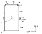
図3、図5、図7、及び図11に示すように、支持部52は、筐体31の底部40を支持する。本実施形態では、この支持部52に、筐体31をねじ締結するための貫通孔53が形成されている。そして、筐体31は、図5に示すねじ34が、貫通孔53を挿通し、自身の底部40に形成されたねじ穴44にねじ込まれて支持部52に固定されている。
As shown in FIGS. 3, 5, 7, and 11, the support portion 52 supports the bottom portion 40 of the housing 31. In the present embodiment, a through hole 53 for screwing the housing 31 is formed in the support portion 52. 5 is fixed to the support portion 52 by inserting the screw 34 shown in FIG. 5 through the through hole 53 and screwing into the screw hole 44 formed in the bottom portion 40 of the housing 31.
また、支持部52は、図5及び図11に示すように、トレイ部54を構成する底板部55に連結されている。図5では、支持部52と底板部55との境界を破線で示している。支持部52は、底板部55のX方向の端部であって、Y方向の両端付近にそれぞれ連結されている。支持部52は、Z方向からの投影視において、筐体31の底部40におけるY方向の両端付近と重なっている。
Moreover, the support part 52 is connected with the baseplate part 55 which comprises the tray part 54, as shown in FIG.5 and FIG.11. In FIG. 5, the boundary between the support portion 52 and the bottom plate portion 55 is indicated by a broken line. The support portion 52 is an end portion in the X direction of the bottom plate portion 55 and is connected to the vicinity of both ends in the Y direction. The support portion 52 overlaps the vicinity of both ends in the Y direction at the bottom portion 40 of the housing 31 in the projection view from the Z direction.
トレイ部54は、ブラケット33のうち、バッテリ19が配置される部分である。このトレイ部54は、底板部55と、横板部56,57と、を有している。底板部55は支持部、横板部57は補強部とも言える。本実施形態では、底板部55及び横板部56,57も、介在部50、板ばね部51、及び支持部52を構成する金属板の一部として構成されている。すなわち、本実施形態では、底板部55と横板部56,57が、同一の金属板の一部として構成されている。しかしながら、底板部55と横板部56,57とは、別部材とすることもできる。さらには、横板部56と横板部57は、別部材とすることもできる。
The tray portion 54 is a portion of the bracket 33 where the battery 19 is disposed. The tray portion 54 has a bottom plate portion 55 and horizontal plate portions 56 and 57. It can be said that the bottom plate portion 55 is a support portion and the horizontal plate portion 57 is a reinforcement portion. In the present embodiment, the bottom plate portion 55 and the horizontal plate portions 56 and 57 are also configured as part of the metal plate that constitutes the interposition portion 50, the leaf spring portion 51, and the support portion 52. That is, in the present embodiment, the bottom plate portion 55 and the horizontal plate portions 56 and 57 are configured as a part of the same metal plate. However, the bottom plate portion 55 and the horizontal plate portions 56 and 57 can be separate members. Furthermore, the horizontal plate portion 56 and the horizontal plate portion 57 may be separate members.
底板部55は、バッテリ19を支持する。底板部55は、XY平面の形状が、バッテリ19に対応して矩形状(長方形)をなしている。上記したように、底板部55のX方向における一端、すなわちバッテリ19の短側面19cに対応する端部の一方には、支持部52が連結されている。また、底板部55は、支持部52が連結された端部において、2つの支持部52の間に介在部50の下端が連結されている。支持部52は、底板部55と同一平面に位置するとともに、底板部55からX方向に延設されている。すなわち、支持部52は、底板部55に対して折曲されていない。一方、介在部50は、底板部55とのなす角度が略90度となるように、底板部55に対して折曲されている。
The bottom plate part 55 supports the battery 19. The bottom plate portion 55 has a rectangular shape (rectangular shape) corresponding to the battery 19 in the shape of the XY plane. As described above, the support portion 52 is connected to one end of the bottom plate portion 55 in the X direction, that is, one of the end portions corresponding to the short side surface 19 c of the battery 19. Further, the bottom plate portion 55 is connected to the lower end of the interposition portion 50 between the two support portions 52 at the end where the support portion 52 is connected. The support portion 52 is located on the same plane as the bottom plate portion 55 and extends from the bottom plate portion 55 in the X direction. That is, the support portion 52 is not bent with respect to the bottom plate portion 55. On the other hand, the interposition part 50 is bent with respect to the bottom plate part 55 so that the angle formed with the bottom plate part 55 is approximately 90 degrees.
底板部55は、中心付近に貫通形成された固定孔58を有している。この固定孔58により、ブラケット33、すなわち電子制御装置20は、車両10のボディ、又は、該ボディに固定された取り付け部に、ねじ締結される。なお、電子制御装置20の車両10への固定部位は、底板部55に限定されない。電子制御装置20は、ブラケット33の他の部分での固定も可能である。また、電子制御装置20は、クランプ部材24を介して、ラジエータサポートなどの取り付け部に固定することもできる。
The bottom plate portion 55 has a fixing hole 58 formed so as to penetrate near the center. With the fixing hole 58, the bracket 33, that is, the electronic control unit 20, is screwed to the body of the vehicle 10 or an attachment portion fixed to the body. Note that the fixed portion of the electronic control device 20 to the vehicle 10 is not limited to the bottom plate portion 55. The electronic control unit 20 can be fixed at other portions of the bracket 33. Further, the electronic control device 20 can be fixed to an attachment portion such as a radiator support via the clamp member 24.
横板部56は、底板部55に対して、介在部50及び支持部52が連結された端部と反対の端部に連結されている。横板部56は、YZ平面の形状が矩形状(長方形)をなしており、Y方向において、底板部55と同じ長さを有している。この横板部56は、底板部55とのなす角度が略90度となるように、底板部55に対して折曲されている。図7に示すように、介在部50と横板部56とは、互いに対向している。
The horizontal plate portion 56 is connected to the end portion of the bottom plate portion 55 opposite to the end portion to which the interposition portion 50 and the support portion 52 are connected. The horizontal plate portion 56 has a rectangular shape (rectangular shape) on the YZ plane, and has the same length as the bottom plate portion 55 in the Y direction. The horizontal plate portion 56 is bent with respect to the bottom plate portion 55 so that the angle formed with the bottom plate portion 55 is approximately 90 degrees. As shown in FIG. 7, the interposition part 50 and the horizontal plate part 56 face each other.
一対の横板部57は、底板部55におけるY方向の端部、すなわちバッテリ19の長側面19bに対応する端部に、それぞれ連結されている。一対の横板部57は、底板部55とのなす角度が略90度となるように、底板部55に対して折曲されている。一対の横板部57は、互いに対向している。横板部57におけるX方向の一端は、たとえば溶接により、横板部56におけるY方向の端部に連結されている。
The pair of horizontal plate portions 57 is connected to the end portion in the Y direction of the bottom plate portion 55, that is, the end portion corresponding to the long side surface 19 b of the battery 19. The pair of horizontal plate portions 57 are bent with respect to the bottom plate portion 55 so that the angle formed with the bottom plate portion 55 is approximately 90 degrees. The pair of horizontal plate portions 57 face each other. One end of the horizontal plate portion 57 in the X direction is connected to an end portion of the horizontal plate portion 56 in the Y direction, for example, by welding.
また、図7に示すように、横板部57におけるX方向の他端は、たとえば溶接により、介在部50におけるY方向の端部に連結されている。すなわち、横板部57は、介在部50に対し、X方向において板ばね部51と反対側に延設されている。一対の横板部57の対向間隔は、介在部50及び横板部56によって保持されている。ブラケット33は、底板部55の周囲を、介在部50及び横板部56,57が取り囲んでいるため、バッテリ19の位置決めが容易であり、バッテリ19の位置ずれも抑制できる。
Moreover, as shown in FIG. 7, the other end of the X direction in the horizontal plate part 57 is connected with the edge part of the Y direction in the interposition part 50, for example by welding. That is, the lateral plate portion 57 extends to the opposite side of the leaf spring portion 51 in the X direction with respect to the interposition portion 50. The facing interval between the pair of horizontal plate portions 57 is held by the interposition portion 50 and the horizontal plate portion 56. Since the bracket 33 surrounds the periphery of the bottom plate portion 55 by the interposition portion 50 and the horizontal plate portions 56 and 57, the positioning of the battery 19 is easy and the displacement of the battery 19 can also be suppressed.
しかしながら、横板部57は、たとえば溶接によって、板ばね部51に連結することもできる。この場合には、図7に示す構成よりも、横板部57の板厚の分、X方向において電子制御装置20の厚みをより薄くすることができる。
However, the lateral plate portion 57 can also be connected to the leaf spring portion 51 by welding, for example. In this case, the thickness of the electronic control device 20 can be made thinner in the X direction by the thickness of the horizontal plate portion 57 than in the configuration shown in FIG.
横板部57のZ方向の高さは、横板部56との連結端からX方向に所定の範囲、具体的には、X方向の中央付近までの範囲において、横板部56とほぼ同じ高さとなっている。一方、介在部50側の端部において、横板部57の高さは、介在部50とほぼ同じ高さとなっている。そして、横板部57の高さは、X方向の中央付近から介在部50側の端部に向けて、徐々に高くなっている。このように、横板部57の高さは、X方向において回路基板30a,30bに近い側の方が高くなっている。また、横板部57には、X方向における中央付近に、フック部材25のJ字状の下端部が掛け止めされる掛け止め部59が形成されている。
The height in the Z direction of the horizontal plate portion 57 is substantially the same as that of the horizontal plate portion 56 in a predetermined range in the X direction from the connecting end with the horizontal plate portion 56, specifically, in a range from the vicinity of the center in the X direction. It is height. On the other hand, at the end on the interposition part 50 side, the height of the horizontal plate part 57 is substantially the same as that of the interposition part 50. The height of the horizontal plate portion 57 gradually increases from the vicinity of the center in the X direction toward the end portion on the interposed portion 50 side. Thus, the height of the horizontal plate portion 57 is higher on the side closer to the circuit boards 30a and 30b in the X direction. Further, the horizontal plate portion 57 is formed with a latching portion 59 around which the J-shaped lower end portion of the hook member 25 is latched near the center in the X direction.
次に、図2に基づき、上記した電子制御装置20の車両10への組み付け手順について説明する。
Next, a procedure for assembling the electronic control device 20 to the vehicle 10 will be described with reference to FIG.
先ず、エンジンコンパートメント17内に、リレーボックス21や、ワイヤハーネス23を含むメインワイヤを配置する。
First, the main wire including the relay box 21 and the wire harness 23 is arranged in the engine compartment 17.
次いで、エンジンモジュールを、車両10の下側からエンジンコンパートメント17内に取り付ける。エンジンモジュールとは、エンジン18に、スタータ、オルタネータ、コンプレッサ等の補機、トランスミッションやドライブシャフト等の駆動系、ショックアブソーバ、ブレーキロータ等の制動系、エアクリーナを除く吸排気系を組み付けてなるものである。さらに、エンジンモジュールは、これらの他にも、エンジンマウンティング部品、アンダーカバー、及びワイヤハーネス22を組み付けられていてもよい。
Next, the engine module is installed in the engine compartment 17 from the lower side of the vehicle 10. The engine module is constructed by assembling the engine 18 with auxiliary equipment such as a starter, alternator and compressor, a drive system such as a transmission and a drive shaft, a braking system such as a shock absorber and a brake rotor, and an intake and exhaust system excluding an air cleaner. is there. Further, in addition to these, the engine module may be assembled with an engine mounting component, an under cover, and a wire harness 22.
次いで、メインワイヤ及びワイヤハーネス22を除く残りのワイヤハーネス、エアクリーナ、電子制御装置20、バッテリ19などの残りの部品を組み付ける。すなわち、エンジン18とリレーボックス21がすでに配置された状態で、エンジン18とリレーボックス21との間に、バッテリ19及び電子制御装置20を組み付ける。
Next, the remaining parts such as the remaining wire harness excluding the main wire and the wire harness 22, the air cleaner, the electronic control unit 20, and the battery 19 are assembled. That is, the battery 19 and the electronic control unit 20 are assembled between the engine 18 and the relay box 21 with the engine 18 and the relay box 21 already arranged.
その際、コネクタ32が、筐体31の底部40に対して上方に位置するように、筐体31を、バッテリ19の短側面19cの横に配置する。そして、車両10のボディ、又は、該ボディに固定された取り付け部に電子制御装置20(ブラケット33)を組み付け、その後に、ブラケット33の底板部55にバッテリ19を配置する。また、コネクタ32に、外部機器側のメスコネクタを嵌合させる。これにより、ワイヤハーネス22,23が回路基板30a,30bに接続される。なお、メスコネクタの嵌合は、バッテリ19の配置前に実施することもできる。
At that time, the housing 31 is disposed beside the short side surface 19 c of the battery 19 so that the connector 32 is positioned above the bottom 40 of the housing 31. Then, the electronic control device 20 (bracket 33) is assembled to the body of the vehicle 10 or an attachment portion fixed to the body, and then the battery 19 is disposed on the bottom plate portion 55 of the bracket 33. Further, the female connector on the external device side is fitted into the connector 32. Thereby, the wire harnesses 22 and 23 are connected to the circuit boards 30a and 30b. The female connector can be fitted before the battery 19 is arranged.
次に、上記した電子制御装置20の効果について説明する。
Next, effects of the electronic control device 20 described above will be described.
本実施形態では、筐体31の連結面43dをX方向に沿う面とするのではなく、連結面43dの少なくとも一部を、裏面43cに近づくほどY方向における一対の連結面43dの間隔が狭くなるように傾斜する斜面部43eとしている。すなわち、本実施形態では、Z方向から見て筐体31を略矩形状とするのではなく、連結面43dの少なくとも一部を、裏面43cに近づくほどY方向における一対の連結面43dの間隔が狭くなるように傾斜する斜面部43eとしている。
In the present embodiment, the connecting surface 43d of the housing 31 is not a surface along the X direction, but the distance between the pair of connecting surfaces 43d in the Y direction becomes narrower as at least a part of the connecting surface 43d approaches the back surface 43c. It is set as the slope part 43e which inclines so that it may become. That is, in the present embodiment, the casing 31 is not substantially rectangular when viewed from the Z direction, but the distance between the pair of connection surfaces 43d in the Y direction increases as the back surface 43c approaches at least a part of the connection surface 43d. It is set as the slope part 43e which inclines so that it may become narrow.
それとともに、本実施形態では、ブラケット33に、一対の連結面43dの斜面部43eにそれぞれ接触して、ばね変形による反力を斜面部43eに付与する金属製の板ばね部51を設けている。ばね変形による反力が斜面部43eに作用すると、斜面部43eはY方向であって反対側の斜面部43e側に押されるとともに、X方向において介在部50側に押される。すなわち、筐体31におけるY方向の両端が、X方向において介在部50側に押される。そして、板ばね部51と介在部50とにより、X方向において筐体31が挟持される。このようにして、筐体31をブラケット33に固定できる。したがって、従来構造、たとえばX方向においてブラケットを筐体にねじ締結する構造や、連結面を斜面でなく厚み方向に沿う面として、ブラケットにより対向面と裏面とを挟み込んで固定する構造に較べ、X方向において電子制御装置20を薄くできる。また、狭持によって固定するため、固定構造を簡素化できる。
At the same time, in the present embodiment, a metal leaf spring portion 51 is provided on the bracket 33 so as to come into contact with the slope portions 43e of the pair of connecting surfaces 43d and to apply a reaction force due to spring deformation to the slope portions 43e. . When a reaction force due to spring deformation acts on the slope portion 43e, the slope portion 43e is pushed to the opposite slope portion 43e side in the Y direction and to the intervention portion 50 side in the X direction. That is, both ends of the housing 31 in the Y direction are pushed toward the interposition part 50 in the X direction. And the housing | casing 31 is clamped in the X direction by the leaf | plate spring part 51 and the interposition part 50. FIG. In this way, the housing 31 can be fixed to the bracket 33. Therefore, compared to a conventional structure, for example, a structure in which the bracket is screwed to the housing in the X direction, or a structure in which the connection surface is not a slope but a surface along the thickness direction, and the opposite surface and the back surface are sandwiched and fixed by the bracket. The electronic control unit 20 can be made thinner in the direction. Moreover, since it fixes by holding, fixing structure can be simplified.
上記のように電子制御装置20を薄くできるため、搭載スペースが限られるエンジンコンパートメント17において、バッテリ19における平面部19dの隣、すなわちバッテリ19の横の狭いスペースに、電子制御装置20を配置できる。これにより、バッテリの下に電子制御装置を配置する構成に較べ、エンジンコンパートメント17の上方に位置するボンネット12の位置を低くすることができる。したがって、車両10の重心位置を低くすることができる。また、ボンネット12の形状自由度が向上するため、ボンネット12の形状を変えやすくなり、意匠性も向上することができる。本実施形態では、電子制御装置20がエンジンコンパートメント17に配置されるため、さらにドライバの視認性(見切り)を向上することもできる。
Since the electronic control unit 20 can be thinned as described above, the electronic control unit 20 can be arranged in the narrow space next to the flat portion 19 d of the battery 19, that is, the side of the battery 19 in the engine compartment 17 where the mounting space is limited. Thereby, compared with the structure which arrange | positions an electronic controller under a battery, the position of the bonnet 12 located above the engine compartment 17 can be made low. Therefore, the position of the center of gravity of the vehicle 10 can be lowered. Moreover, since the freedom degree of the shape of the bonnet 12 improves, it becomes easy to change the shape of the bonnet 12, and the design property can also be improved. In this embodiment, since the electronic control unit 20 is disposed in the engine compartment 17, the visibility (parting) of the driver can be further improved.
また、筐体31の開口部41、換言すればコネクタ32が、底部40に対して上方となるように配置される。したがって、バッテリの下に電子制御装置を配置する構成のように、下側から上方へワイヤハーネスを配索しなくともよい。さらに、ワイヤハーネス22,23の長さを短くできる。
Further, the opening 41 of the housing 31, in other words, the connector 32 is arranged so as to be above the bottom 40. Therefore, it is not necessary to route the wire harness from the lower side to the upper side as in the configuration in which the electronic control device is arranged under the battery. Furthermore, the length of the wire harnesses 22 and 23 can be shortened.
このように、本実施形態によれば、バッテリ19の隣に配置される電子制御装置20において、ワイヤハーネス22,23が長くなるのを抑制しつつエンジンコンパートメント17上のボンネット12の位置が高くなるのを抑制できる。
As described above, according to the present embodiment, in the electronic control device 20 arranged next to the battery 19, the position of the bonnet 12 on the engine compartment 17 is increased while suppressing the wire harnesses 22 and 23 from becoming longer. Can be suppressed.
また、回路基板30a,30bの熱が、金属製の筐体31を通じて、介在部50及び板ばね部51に伝わる。したがって、金属製の介在部50及び板ばね部51により、回路基板30a,30bの熱を効率よく放熱させることができる。また、エンジンコンパートメント17の下部は、トランスミッションや排気系部品が配置されていること、走行安定性を向上させるためのアンダーカバーで風が流れにくいことから、熱がこもりやすく、上部よりも温度が高い。したがって、バッテリの下に電子制御装置を配置する構成よりも、回路基板30a,30bの熱を効率よく放熱させることができる。
Further, the heat of the circuit boards 30 a and 30 b is transmitted to the interposition part 50 and the leaf spring part 51 through the metal casing 31. Therefore, the heat of the circuit boards 30a and 30b can be efficiently radiated by the metallic interposition part 50 and the leaf spring part 51. In addition, the lower part of the engine compartment 17 has transmissions and exhaust system parts, and the under cover for improving running stability makes it difficult for wind to flow. . Therefore, the heat of the circuit boards 30a and 30b can be radiated more efficiently than the configuration in which the electronic control device is disposed under the battery.
また、電子制御装置20は、第1回路基板30aに位置決め穴30a1が設けられている。電子制御装置20は、位置決め穴30a1に回路素子30cの一部が挿入されることで、回路素子30cの位置ずれを抑制できる。また、電子制御装置20は、第1回路基板30aの位置決め穴30a1に配置された回路素子30cを第1回路基板30aに押し付ける第2回路基板30bを備えている。つまり、電子制御装置は、位置決め穴30a1と第2回路基板30bで、回路素子30cの位置ずれを抑制している。したがって、電子制御装置20は、回路素子30cに外力が印加された場合であっても、回路素子30cが位置ずれしにくい。このように、電子制御装置20は、回路素子30cが位置ずれしにくいため、回路素子30cと第1回路基板30aとの接続部である素子側端子30c1やはんだ60の耐久性を向上できる。さらに、電子制御装置20は、回路素子30cの一部が位置決め穴30a1に挿入されているので、その分だけ、厚みを薄くできる。よって、電子制御装置20は、バッテリ19の横の狭いスペースに配置しやすい。なお、電子制御装置20は、筐体31及びコネクタ32を備えていなくても、この効果を達成できる。また、電子制御装置20は、ポッティング材70が設けられていなくても、この効果を達成できる。
Further, the electronic control device 20 is provided with a positioning hole 30a1 in the first circuit board 30a. The electronic control unit 20 can suppress the displacement of the circuit element 30c by inserting a part of the circuit element 30c into the positioning hole 30a1. In addition, the electronic control unit 20 includes a second circuit board 30b that presses the circuit element 30c disposed in the positioning hole 30a1 of the first circuit board 30a against the first circuit board 30a. That is, the electronic control device suppresses the positional deviation of the circuit element 30c by the positioning hole 30a1 and the second circuit board 30b. Therefore, even when an external force is applied to the circuit element 30c, the electronic control device 20 is unlikely to shift the position of the circuit element 30c. As described above, the electronic control device 20 can improve the durability of the element-side terminal 30c1 and the solder 60, which are connection portions between the circuit element 30c and the first circuit board 30a, because the circuit element 30c is not easily displaced. Furthermore, since a part of the circuit element 30c is inserted into the positioning hole 30a1, the electronic control device 20 can be reduced in thickness accordingly. Therefore, the electronic control device 20 can be easily placed in a narrow space beside the battery 19. The electronic control device 20 can achieve this effect even if it does not include the housing 31 and the connector 32. In addition, the electronic control device 20 can achieve this effect even if the potting material 70 is not provided.
また、電子制御装置20は、筐体31内に、第1回路基板30a及び回路素子30cを覆うポッティング材70が設けられている。このポッティング材70は、筐体31内に設ける際に、筐体31内に流し込むことが考えられる。この場合、回路素子30cには、筐体31内に流れ込んでくるポッティング材70が当たるため、ポッティング材70によって外力が印加されることになる。しかしながら、電子制御装置20は、上記のように、位置決め穴30a1と第2回路基板30bで、電子部品の位置ずれを抑制しているため、筐体31内にポッティング材70を流し込む際にも回路素子30cが位置ずれしにくい。よって、電子制御装置20は、回路素子30cが位置ずれした状態で、ポッティング材70で封止されることを抑制できる。
In the electronic control device 20, a potting material 70 that covers the first circuit board 30 a and the circuit element 30 c is provided in the housing 31. It is conceivable that the potting material 70 is poured into the casing 31 when it is provided in the casing 31. In this case, since the potting material 70 that flows into the housing 31 hits the circuit element 30c, an external force is applied by the potting material 70. However, as described above, the electronic control device 20 suppresses the displacement of the electronic component by the positioning hole 30a1 and the second circuit board 30b. The element 30c is difficult to be displaced. Therefore, the electronic control unit 20 can suppress the sealing with the potting material 70 in a state where the circuit element 30c is displaced.
例えば、回路素子30cは、位置ずれした場合、素子側端子30c1やはんだ60に応力が印加されることがある。よって、回路素子30cは、位置ずれしたままポッティング材70で封止されると、素子側端子30c1やはんだ60に応力が印加された状態で第1回路基板30aに固定されることになる。このため、素子側端子30c1やはんだ60は、素子側端子30c1が折れたり、はんだ60にクラックが入ったりしやすい。しかしながら、電子制御装置20は、回路素子30cが位置ずれした状態で固定されることを抑制できるため、ポッティング材70が設けられる場合であっても、素子側端子30c1やはんだ60の耐久性を向上できる。
For example, when the circuit element 30c is displaced, stress may be applied to the element-side terminal 30c1 or the solder 60. Therefore, when the circuit element 30c is sealed with the potting material 70 while being displaced, the circuit element 30c is fixed to the first circuit board 30a in a state where stress is applied to the element-side terminal 30c1 and the solder 60. For this reason, the element side terminal 30c1 and the solder 60 are liable to break the element side terminal 30c1 or to crack the solder 60. However, since the electronic control unit 20 can suppress the circuit element 30c from being fixed in a misaligned state, the durability of the element-side terminal 30c1 and the solder 60 is improved even when the potting material 70 is provided. it can.
このように、電子制御装置20は、第1回路基板30aと第2回路基板30bとを備えている。第2回路基板30bは、筐体31内に収容されるとともに第1回路基板30aの実装面に対向配置され、且つ、ポッティング材70で覆われている。このように、第2回路基板30bは、第1回路基板30aの実装面に対向配置されている。そこで、本実施形態では、第2回路基板30bを押さえ部材として採用する。このため、第2回路基板30bは、回路素子30cを第1回路基板30aに押し付けるように設けられている。本実施形態では、電子制御装置20に設けられている部品である第2回路基板30bを押さえ部材として採用しているため、部品点数を増やすことなく回路素子30cを第1回路基板30aに押し付けることができる。
As described above, the electronic control device 20 includes the first circuit board 30a and the second circuit board 30b. The second circuit board 30 b is accommodated in the housing 31, is disposed to face the mounting surface of the first circuit board 30 a, and is covered with the potting material 70. As described above, the second circuit board 30b is disposed to face the mounting surface of the first circuit board 30a. Therefore, in the present embodiment, the second circuit board 30b is employed as a pressing member. For this reason, the second circuit board 30b is provided so as to press the circuit element 30c against the first circuit board 30a. In the present embodiment, since the second circuit board 30b, which is a component provided in the electronic control device 20, is employed as the pressing member, the circuit element 30c is pressed against the first circuit board 30a without increasing the number of components. Can do.
また、回路素子30cは、円柱形状の胴体部を有しており、筒状部が実装面と平行で、円形壁部が実装面と垂直となるように配置されている。通常、このような回路素子30cは、素子側端子30c1が第1回路基板30aに挿入されているだけでは、外力が印加されると位置ずれしやすい。しかしながら、電子制御装置20は、位置決め穴30a1と第2回路基板30bで、回路素子30cの位置ずれを抑制しているため、このような回路素子30cであっても位置ずれを抑制できる。
The circuit element 30c has a cylindrical body part, and is arranged so that the cylindrical part is parallel to the mounting surface and the circular wall part is perpendicular to the mounting surface. Normally, such a circuit element 30c is likely to be displaced when an external force is applied only by inserting the element-side terminal 30c1 into the first circuit board 30a. However, since the electronic control unit 20 suppresses the positional deviation of the circuit element 30c by the positioning hole 30a1 and the second circuit board 30b, the positional deviation can be suppressed even by such a circuit element 30c.
さらに本実施形態では、Z方向からみて、筐体31の形状を台形状としている。すなわち、連結面43dのほぼ全面を斜面部43eとしている。このような構成によれば、筐体31とブラケット33とを固定しやすい。たとえば外力を印加して一対の板ばね部51を少し開いた状態で、筐体31をZ方向に所定位置まで移動させた後、外力の印加を解除することで、筐体31とブラケット33とを固定することができる。また、連結面43dが、一部のみに斜面部43eを有し、残りの部分がX方向に沿う(すなわち斜面部43eを有さない)構成に較べて、筐体31を形成しやすい。なお、板ばね部51のうち、上端から所定の範囲で、下端に向かうほど介在部50とのなす角度が小さくなるようにしておくと、外力を印加せずとも、筐体31を所定位置まで移動させることができる。また、上記したように、板ばね部51の接触面側に楔状や半球状など突起を設けておいても、外力の印加により板ばね部51を開くことをせずに、筐体31を所定位置まで移動させることができる。
Furthermore, in this embodiment, the shape of the housing | casing 31 is made into trapezoid shape seeing from a Z direction. That is, the substantially entire surface of the connecting surface 43d is a slope portion 43e. According to such a configuration, it is easy to fix the housing 31 and the bracket 33. For example, in a state where the pair of leaf springs 51 is slightly opened by applying an external force, the housing 31 is moved to a predetermined position in the Z direction, and then the application of the external force is canceled, so that the housing 31 and the bracket 33 Can be fixed. Further, the connecting surface 43d can form the housing 31 more easily than a configuration in which the connection surface 43d has a slope portion 43e only in a part and the remaining portion is along the X direction (that is, does not have the slope portion 43e). If the angle between the leaf spring portion 51 and the interposition portion 50 is reduced within a predetermined range from the upper end toward the lower end, the casing 31 can be moved to a predetermined position without applying external force. Can be moved. In addition, as described above, even when a protrusion such as a wedge shape or a hemisphere is provided on the contact surface side of the leaf spring portion 51, the casing 31 is fixed to the predetermined portion without opening the leaf spring portion 51 by applying an external force. It can be moved to a position.
さらに本実施形態では、ブラケット33が支持部52を有しており、この支持部52により、筐体31が支持されている。したがって、車両振動の印加にともなって、筐体31が下方に位置ずれするのを抑制できる。すなわち、筐体31をより安定して固定することができる。特に本実施形態では、支持部52に、貫通孔53が形成されており、この貫通孔53を通じて、筐体31が支持部52にねじ締結される。このように、筐体31における底部40の下でねじ締結されているため、ブラケット33、すなわち車両10から筐体31を取り外しにくい。したがって、エンジンコンパートメント17から回路基板30a,30bを含む筐体31が取り出される(たとえば盗難される)のを抑制できる。特に本実施形態では、支持部52が金属材料を用いて形成されているため、回路基板30a,30bの熱が、金属製の筐体31の底部40を通じて、支持部52にも伝わる。したがって、回路基板30a,30bの熱を効率よく放熱できる。
Furthermore, in the present embodiment, the bracket 33 has a support portion 52, and the housing 31 is supported by the support portion 52. Therefore, it is possible to prevent the casing 31 from being displaced downward with the application of vehicle vibration. That is, the housing 31 can be fixed more stably. In particular, in the present embodiment, a through hole 53 is formed in the support portion 52, and the housing 31 is screwed to the support portion 52 through the through hole 53. As described above, since the screw is fastened under the bottom portion 40 of the housing 31, it is difficult to remove the housing 31 from the bracket 33, that is, the vehicle 10. Therefore, it is possible to prevent the housing 31 including the circuit boards 30a and 30b from being taken out (for example, stolen) from the engine compartment 17. In particular, in the present embodiment, since the support portion 52 is formed using a metal material, the heat of the circuit boards 30 a and 30 b is also transmitted to the support portion 52 through the bottom portion 40 of the metal casing 31. Therefore, the heat of the circuit boards 30a and 30b can be radiated efficiently.
さらに本実施形態では、ブラケット33が横板部57を有している。横板部57は、介在部50又は板ばね部51に連結されて、介在部50から板ばね部51が延びる方向と反対の方向に延設されている。したがって、回路基板30a,30bや筐体31などの重みで、板ばね部51及び介在部50が倒れるのを抑制できる。すなわち、回路基板30a,30bを含む筐体31を、バッテリ19の横により安定的に保持できる。特に本実施形態では、横板部57が金属材料を用いて形成されているため、回路基板30a,30bの熱が横板部57にも伝わる。このように、ブラケット33全体の熱マスが増加し、回路基板30a,30bの熱をより効果的に放熱させることができる。なお、熱マスとは、熱を吸収できる容積を示す。
Furthermore, in the present embodiment, the bracket 33 has a horizontal plate portion 57. The lateral plate portion 57 is connected to the interposed portion 50 or the leaf spring portion 51 and extends in a direction opposite to the direction in which the leaf spring portion 51 extends from the interposed portion 50. Therefore, it is possible to prevent the leaf spring portion 51 and the interposition portion 50 from falling due to the weight of the circuit boards 30a, 30b, the casing 31, and the like. That is, the casing 31 including the circuit boards 30 a and 30 b can be stably held by the side of the battery 19. In particular, in the present embodiment, since the horizontal plate portion 57 is formed using a metal material, the heat of the circuit boards 30 a and 30 b is also transmitted to the horizontal plate portion 57. Thus, the thermal mass of the entire bracket 33 is increased, and the heat of the circuit boards 30a and 30b can be radiated more effectively. The thermal mass indicates a volume capable of absorbing heat.
さらに本実施形態では、ブラケット33が底板部55を有しており、バッテリ19を支持することができる。特に本実施形態では、底板部55が金属材料を用いて形成されているため、回路基板30a,30bの熱が底板部55にも伝わる。このように、ブラケット33全体の熱マスが増加し、回路基板30a,30bの熱をより効果的に放熱させることができる。言い換えると、本実施形態では、ブラケット33に伝搬した熱の放熱経路として横板部57や底板部55を用いることができる。
Further, in the present embodiment, the bracket 33 has the bottom plate portion 55 and can support the battery 19. In particular, in the present embodiment, since the bottom plate portion 55 is formed using a metal material, the heat of the circuit boards 30 a and 30 b is also transmitted to the bottom plate portion 55. Thus, the thermal mass of the entire bracket 33 is increased, and the heat of the circuit boards 30a and 30b can be radiated more effectively. In other words, in the present embodiment, the horizontal plate portion 57 and the bottom plate portion 55 can be used as a heat dissipation path for the heat propagated to the bracket 33.
本実施形態では、底板部55及び横板部57を含んでトレイ部54が構成されており、ブラケット33により、筐体31に加えてバッテリ19も支持することができる。特に本実施形態では、介在部50、板ばね部51、及び支持部52と、バッテリ19を支持するトレイ部54の構成要素(底板部55、横板部56,57)が、同一の金属板の一部として構成されている。したがって、トレイ部54を含めたブラケット33の構成を簡素化することができる。また、回路基板30a,30bの熱をトレイ部54全体に放熱させることができる。言い換えると、本実施形態では、ブラケット33に伝搬した熱の放熱経路としてトレイ部54を用いることができる。
In the present embodiment, the tray portion 54 is configured including the bottom plate portion 55 and the horizontal plate portion 57, and the battery 19 can be supported by the bracket 33 in addition to the housing 31. In particular, in this embodiment, the interposition part 50, the leaf spring part 51, the support part 52, and the components (the bottom plate part 55, the lateral plate parts 56, 57) of the tray part 54 that supports the battery 19 are the same metal plate. Is configured as part of Therefore, the configuration of the bracket 33 including the tray portion 54 can be simplified. Further, the heat of the circuit boards 30 a and 30 b can be radiated to the entire tray portion 54. In other words, in the present embodiment, the tray portion 54 can be used as a heat dissipation path for the heat propagated to the bracket 33.
さらに本実施形態では、箱状部材としてのバッテリ19の横に電子制御装置20の筐体31を配置している。エンジンコンパートメント17において、バッテリ19は、エンジン18の周辺ではなく、フロントグリル15からの風が通る温度の低い場所に配置される。したがって、バッテリ19の横に回路基板30a,30bを配置することで、回路基板30a,30bの温度上昇を効果的に抑制することもできる。
Furthermore, in this embodiment, the housing | casing 31 of the electronic control apparatus 20 is arrange | positioned beside the battery 19 as a box-shaped member. In the engine compartment 17, the battery 19 is disposed not in the vicinity of the engine 18 but in a place where the temperature from the front grill 15 is low. Therefore, by arranging the circuit boards 30a and 30b beside the battery 19, the temperature rise of the circuit boards 30a and 30b can be effectively suppressed.
ところで、バッテリ19の側面のうち、長側面19bの隣に筐体31を配置することも可能である。しかしながら、長側面19bの隣に配置すると、フック部材25を避けるように、ワイヤハーネス22,23を配索しなければならない。このため、ワイヤハーネス22,23の長さが長くなる。また、配索のためのスペースも必要となる。これに対し、本実施形態では、バッテリ19の短側面19cの隣に、筐体31が配置するため、これによってもワイヤハーネス22,23の長さを短くすることができる。
By the way, it is also possible to arrange | position the housing | casing 31 next to the long side surface 19b among the side surfaces of the battery 19. FIG. However, if arranged next to the long side surface 19b, the wire harnesses 22 and 23 must be routed so as to avoid the hook member 25. For this reason, the length of the wire harnesses 22 and 23 becomes long. In addition, a space for wiring is required. On the other hand, in this embodiment, since the housing | casing 31 is arrange | positioned next to the short side surface 19c of the battery 19, the length of the wire harnesses 22 and 23 can also be shortened by this.
以上、本発明の好ましい実施形態について説明した。しかしながら、本発明は、上記した実施形態に何ら制限されることはなく、本発明の趣旨を逸脱しない範囲において、種々の変形が可能である。以下に、本発明の変形例に関して説明する。上記の実施形態及び変形例は、それぞれ単独で実施することも可能であるが、適宜組み合わせて実施することも可能である。本発明は、発明を実施するための形態において示された組み合わせに限定されることなく、種々の組み合わせによって実施可能である。
The preferred embodiments of the present invention have been described above. However, the present invention is not limited to the above-described embodiments, and various modifications can be made without departing from the spirit of the present invention. Below, the modification of this invention is demonstrated. The above-described embodiments and modification examples can be implemented independently, but can be implemented in combination as appropriate. The present invention is not limited to the combinations shown in the mode for carrying out the invention, and can be implemented in various combinations.
(変形例1)
本変形例において、上記実施形態に示した電子制御装置20と共通する部分についての説明は割愛する。
(Modification 1)
In this modification, the description of the parts common to the electronic control device 20 shown in the above embodiment is omitted.
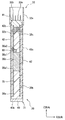
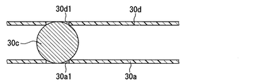
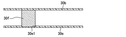
図17に示すように、変形例1の電子制御装置は、第1回路基板30aだけではなく、第2回路基板30dにも位置決め穴30d1が設けられている。第2回路基板30dは、自身の厚み方向に貫通した位置決め穴30d1が設けられている。第2回路基板30dは、位置決め穴30a1に対向する位置に、位置決め穴30d1が設けられている。この位置決め穴30d1は、特許請求の範囲における第2穴部に相当する。また、図17は、図13に相当する図面である。
As shown in FIG. 17, in the electronic control device of Modification 1, not only the first circuit board 30a but also the second circuit board 30d is provided with positioning holes 30d1. The second circuit board 30d is provided with a positioning hole 30d1 penetrating in the thickness direction of the second circuit board 30d. The second circuit board 30d has a positioning hole 30d1 at a position facing the positioning hole 30a1. The positioning hole 30d1 corresponds to the second hole in the claims. FIG. 17 corresponds to FIG.
変形例1の電子制御装置は、電子制御装置20と同様の効果を奏することができる。さらに、変形例1の電子制御装置は、回路素子30cの一部が第1回路基板30aに埋設されるだけでなく、回路素子30cの他の一部が第2回路基板30dに埋設されるため、電子制御装置20よりも厚みを薄くできる。また、変形例1の電子制御装置は、回路素子30cが、両位置決め穴30a1,30d1に埋設されているため、電子制御装置20よりも固定強度を向上できる。
The electronic control device of Modification 1 can achieve the same effects as the electronic control device 20. Furthermore, in the electronic control device according to the first modification, not only a part of the circuit element 30c is embedded in the first circuit board 30a but also another part of the circuit element 30c is embedded in the second circuit board 30d. The thickness can be made thinner than that of the electronic control unit 20. Further, in the electronic control device according to the first modification, since the circuit element 30c is embedded in both the positioning holes 30a1 and 30d1, the fixing strength can be improved as compared with the electronic control device 20.
なお、位置決め穴30d1は、第2回路基板30dの厚み方向に貫通した部位ではなく、周辺よりも窪んだ凹状の部位であってもよい。同様に、位置決め穴30a1は、第1回路基板30aの厚み方向に貫通した部位ではなく、周辺よりも窪んだ凹状の部位であってもよい。
The positioning hole 30d1 may be a concave portion that is recessed from the periphery, instead of a portion that penetrates in the thickness direction of the second circuit board 30d. Similarly, the positioning hole 30a1 may not be a part penetrating in the thickness direction of the first circuit board 30a but may be a concave part recessed from the periphery.
(変形例2)
本変形例において、上記実施形態に示した電子制御装置20と共通する部分についての説明は割愛する。
(Modification 2)
In this modification, the description of the parts common to the electronic control device 20 shown in the above embodiment is omitted.
図18に示すように、変形例2の電子制御装置20aは、電子制御装置20と異なり、第2回路基板30bが設けられていない。このため、コネクタ321は、コネクタ32と同様に第1端子32bを有しているが、コネクタ32と異なり第2端子32cを有していない。つまり、ハウジング321aには、第1端子32bが設けられており、第2端子32cが設けられていない。
As shown in FIG. 18, unlike the electronic control device 20, the electronic control device 20a of Modification 2 is not provided with the second circuit board 30b. For this reason, the connector 321 has the first terminal 32b like the connector 32, but unlike the connector 32, the connector 321 does not have the second terminal 32c. That is, the housing 321a is provided with the first terminal 32b and is not provided with the second terminal 32c.
そして、電子制御装置20aは、筐体31aにおける第1回路基板30aの実装面に対向する部位が、回路素子30cに接触している。つまり、電子制御装置20aは、筐体31aが、回路素子30cを第1回路基板30aに押し付けている。このように、筐体31aは、特許請求の範囲における押さえ部材に相当する部位を備えている。つまり、筐体31aにおける第1回路基板30aの実装面に対向する部位は、特許請求の範囲における押さえ部材に相当する。電子制御装置20aは、電子制御装置20と同様の効果を奏することができる。
In the electronic control device 20a, a portion of the housing 31a that faces the mounting surface of the first circuit board 30a is in contact with the circuit element 30c. That is, in the electronic control unit 20a, the casing 31a presses the circuit element 30c against the first circuit board 30a. Thus, the housing | casing 31a is provided with the site | part corresponded to the pressing member in a claim. That is, the part of the housing 31a that faces the mounting surface of the first circuit board 30a corresponds to the pressing member in the claims. The electronic control device 20a can achieve the same effects as the electronic control device 20.
(変形例3)
本変形例において、上記実施形態に示した電子制御装置20と共通する部分についての説明は割愛する。
(Modification 3)
In this modification, the description of the parts common to the electronic control device 20 shown in the above embodiment is omitted.
図19、図20に示すように、変形例3の電子制御装置20bは、第1回路基板30eの構成と、回路素子30fの構成が電子制御装置20と異なる。図20は、図19をZ方向から見た図である。
As illustrated in FIGS. 19 and 20, the electronic control device 20 b of Modification 3 is different from the electronic control device 20 in the configuration of the first circuit board 30 e and the configuration of the circuit element 30 f. FIG. 20 is a view of FIG. 19 viewed from the Z direction.
第1回路基板30eは、周辺よりも窪んだ位置決め穴30e1が設けられている。このように、第1回路基板30eは、位置決め穴30e1の形状が第1回路基板30aと異なる。つまり、位置決め穴30e1は、第1回路基板30eの厚み方向に貫通した部位ではなく、周辺よりも窪んだ凹状の部位である。なお、第1回路基板30eは、第1回路基板30aと同様に、素子側端子30f1が挿入されるスルーホール30e2が形成されている。
The first circuit board 30e is provided with a positioning hole 30e1 that is recessed from the periphery. Thus, the first circuit board 30e is different from the first circuit board 30a in the shape of the positioning hole 30e1. That is, the positioning hole 30e1 is not a part penetrating in the thickness direction of the first circuit board 30e, but a concave part recessed from the periphery. The first circuit board 30e is formed with a through hole 30e2 into which the element side terminal 30f1 is inserted, like the first circuit board 30a.
また、回路素子30fは、はんだ60を介して素子側端子30f1と第1回路基板30eとが電気的及び機械的に接続され、第1回路基板30eの実装面側に実装されている。回路素子30fは、回路素子30cと異なり立方体形状である。本変形例では、回路素子30fとしてTHDのインダクタを採用している。詳述すると、回路素子30fは、立方体形状の胴体部と、胴体部から突出した二つの素子側端子30f1とを有している。つまり、回路素子30fの胴体部は、筒状部と、筒状部の両端に形成された矩形壁部とを含む形状である。そして、回路素子30fは、二つの矩形壁部の一方から各素子側端子30f1が突出して形成されている。各素子側端子30f1は、各素子側端子30c1と同様にL字形状である。回路素子30fは、回路素子30cと同様に、第1回路基板30eに対して横置き実装されている。
The circuit element 30f is mounted on the mounting surface side of the first circuit board 30e by electrically and mechanically connecting the element side terminal 30f1 and the first circuit board 30e via the solder 60. Unlike the circuit element 30c, the circuit element 30f has a cubic shape. In this modification, a THD inductor is used as the circuit element 30f. More specifically, the circuit element 30f has a cube-shaped body portion and two element-side terminals 30f1 protruding from the body portion. That is, the body part of the circuit element 30f has a shape including a cylindrical part and rectangular wall parts formed at both ends of the cylindrical part. The circuit element 30f is formed such that each element-side terminal 30f1 protrudes from one of the two rectangular walls. Each element side terminal 30f1 is L-shaped like each element side terminal 30c1. Similarly to the circuit element 30c, the circuit element 30f is mounted horizontally with respect to the first circuit board 30e.
電子制御装置20bは、電子制御装置20と同様の効果を奏することができる。なお、電子制御装置20bは、回路素子30fのかわりに回路素子30cを備えていてもよい。
The electronic control device 20b can achieve the same effects as the electronic control device 20. The electronic control device 20b may include a circuit element 30c instead of the circuit element 30f.
(変形例4)
本変形例において、上記実施形態に示した電子制御装置20と共通する部分についての説明は割愛する。
(Modification 4)
In this modification, the description of the parts common to the electronic control device 20 shown in the above embodiment is omitted.
図21、図22に示すように、変形例4の電子制御装置は、第1回路基板30gの構成と、回路素子30hの構成が電子制御装置と異なる。
As shown in FIGS. 21 and 22, the electronic control device of Modification 4 is different from the electronic control device in the configuration of the first circuit board 30 g and the configuration of the circuit element 30 h.
第1回路基板30gは、図21に示すように、第1回路基板30eと同様に、周辺よりも窪んだ位置決め穴30g1が設けられている。また、第1回路基板30gは、図22に示すように、位置決め穴30g1の表面に、導電性のランド30g2が形成されている。ここでは、二つのランド30g2が形成された第1回路基板30gを採用している。また、第1回路基板30gは、自身の実装面に沿う平面において、二つのランド30g2の対向方向に直交する方向に、回路素子30hが位置ずれすることを抑制するための位置決め穴30g1が設けられている。
As shown in FIG. 21, the first circuit board 30g is provided with a positioning hole 30g1 that is recessed from the periphery, like the first circuit board 30e. Further, as shown in FIG. 22, the first circuit board 30g has a conductive land 30g2 formed on the surface of the positioning hole 30g1. Here, the first circuit board 30g on which two lands 30g2 are formed is employed. In addition, the first circuit board 30g is provided with a positioning hole 30g1 for suppressing displacement of the circuit element 30h in a direction orthogonal to the facing direction of the two lands 30g2 on a plane along its mounting surface. ing.
回路素子30hは、回路素子30cと同様に、円柱形状の胴体部を備えている。しかしながら、回路素子30hは、回路素子30cと異なり、SMD(Surface Mount Device)構造である。例えば、回路素子30hは、SMDのアルミ電解コンデンサである。回路素子30hは、図22に示すように、円形壁部に二つの電極30h1が形成されている。そして、回路素子30hは、円形壁部が第1回路基板30gの実装面と対向して、第1回路基板30gに実装されている。また、回路素子30hは、電極30h1とランド30g2とがはんだ60(図示せず)を介して電気的及び機械的に接続された状態で、第1回路基板30gに実装されている。
The circuit element 30h includes a cylindrical body part, like the circuit element 30c. However, unlike the circuit element 30c, the circuit element 30h has an SMD (Surface Mount Device) structure. For example, the circuit element 30h is an SMD aluminum electrolytic capacitor. As shown in FIG. 22, the circuit element 30h has two electrodes 30h1 formed on a circular wall portion. The circuit element 30h is mounted on the first circuit board 30g with the circular wall portion facing the mounting surface of the first circuit board 30g. The circuit element 30h is mounted on the first circuit board 30g in a state where the electrode 30h1 and the land 30g2 are electrically and mechanically connected via a solder 60 (not shown).
なお、変形例4の電子制御装置は、図示は省略しているが、第2回路基板30bや筐体31aで回路素子30hを第1回路基板30gに押し付けている。さらに、変形例4の電子制御装置は、円形壁部に垂直に端子が突出したTHD構造の回路素子30hでも採用できる。変形例4の電子制御装置は、電子制御装置20と同様の効果を奏することができる。
Note that the electronic control device of Modification 4 is not shown, but the circuit element 30h is pressed against the first circuit board 30g by the second circuit board 30b or the casing 31a. Furthermore, the electronic control device according to the modified example 4 can also be used in the circuit element 30h having a THD structure in which the terminals protrude perpendicularly to the circular wall portion. The electronic control device according to the modified example 4 can achieve the same effects as the electronic control device 20.
(変形例5)
本変形例において、上記実施形態に示した電子制御装置20と共通する部分についての説明は割愛する。図23に示すように、電子制御装置20cのコネクタ32や筐体31は、電子制御装置20におけるものと形状が異なるが、便宜上、同じ符号を付与している。
(Modification 5)
In this modification, the description of the parts common to the electronic control device 20 shown in the above embodiment is omitted. As shown in FIG. 23, the connector 32 and the casing 31 of the electronic control device 20c are different in shape from those in the electronic control device 20, but are given the same reference numerals for convenience.
図23に示すように、変形例5の電子制御装置20cは、押さえ部材としてコンポーネントキャリア35を採用している。コンポーネントキャリア35は、樹脂製ハウジング35aに配線パターンと発熱素子35bが内蔵され、ピン35cを用いて第1回路基板30aと電気的に接続されている。また、発熱素子35bは、放熱ゲル80で筐体31と接触させてもよい。なお、コンポーネントキャリア35に関しては、特開2005−333077号公報を参照されたい。
As shown in FIG. 23, the electronic control unit 20c of the fifth modification employs a component carrier 35 as a pressing member. The component carrier 35 has a wiring pattern and a heating element 35b built in a resin housing 35a, and is electrically connected to the first circuit board 30a using pins 35c. Further, the heat generating element 35 b may be brought into contact with the housing 31 with the heat radiating gel 80. For the component carrier 35, refer to Japanese Patent Application Laid-Open No. 2005-333077.
このように、電子制御装置20cは、コンポーネントキャリア35が回路素子30cを第1回路基板30aに押し付けている。電子制御装置20cは、電子制御装置20と同様の効果を奏することができる。
Thus, in the electronic control unit 20c, the component carrier 35 presses the circuit element 30c against the first circuit board 30a. The electronic control device 20c can achieve the same effects as the electronic control device 20.
(変形例6)
本変形例は、先行実施形態及びや先行変形例を参照できる。このため、先行実施形態やや先行変形例に示した電子制御装置20などと共通する部分についての説明は省略する。
(Modification 6)
For this modification, reference can be made to the preceding embodiment and the preceding modification. For this reason, the description about the part which is common in the electronic control apparatus 20 etc. which were shown in the preceding embodiment and the previous modification is abbreviate | omitted.
先ず、図24〜図27に基づき、変形例6の電子制御装置20d、特に第1回路基板30a及びコネクタ32を含む筐体31bについて説明する。図26及び図27では、便宜上、コネクタ32の端子32bを省略している。
First, based on FIGS. 24 to 27, the electronic control device 20 d of Modification 6, particularly the housing 31 b including the first circuit board 30 a and the connector 32 will be described. 26 and 27, the terminal 32b of the connector 32 is omitted for convenience.
本変形例の筐体31bは、中間ケース81と、中間ケース81に対してX方向の一面側に配置される上ケース82と、中間ケース81に対して上ケース82と反対側に配置される下ケース83と、を有している。すなわち、複数の部材により、筐体31bが構成されている。これら中間ケース81、上ケース82、及び下ケース83が、筐体構成部材に相当する。中間ケース81、上ケース82、及び下ケース83は、垂直な方向に分割可能に構成されている。さらに筐体31bは、板ばね部51が接触する部分である一対の受け部84を有している。
The casing 31b of the present modification is disposed on the opposite side of the upper case 82 with respect to the intermediate case 81, the upper case 82 disposed on one surface side in the X direction with respect to the intermediate case 81. And a lower case 83. That is, the housing 31b is configured by a plurality of members. The intermediate case 81, the upper case 82, and the lower case 83 correspond to a casing constituent member. The intermediate case 81, the upper case 82, and the lower case 83 are configured to be divided in the vertical direction. Further, the housing 31b has a pair of receiving portions 84 that are portions where the leaf spring portion 51 contacts.
中間ケース81は、樹脂成形体である。本変形例では、中間ケース81が、熱可塑性樹脂を用いて形成されている。熱可塑性樹脂としては、耐熱性に優れるもの、たとえばポリブチレンテレフタレート(PBT)を採用することができる。
The intermediate case 81 is a resin molded body. In this modification, the intermediate case 81 is formed using a thermoplastic resin. As the thermoplastic resin, one having excellent heat resistance, such as polybutylene terephthalate (PBT) can be employed.
中間ケース81は環状をなしており、X方向に沿う貫通孔81aを有している。このため、中間ケース81を枠体と称することもできる。具体的には、図25及び図26に示すように、中間ケース81は略矩形環状をなしている。この中間ケース81には、図24に示すように、コネクタ32のハウジング32aが一体化されている。換言すれば、ハウジング32aが、中間ケース81の一部分として一体的に成形されている。しかしながら、中間ケース81の形状は上記例に限定されない。たとえば略C字状(換言すれば略コの字状)の中間ケース81を採用し、中間ケース81のC字の開口部(間隙部)にハウジング32aが配置された構成を採用することもできる。この場合、溶着により、中間ケース81とハウジング32aとをシールすることもできる。
The intermediate case 81 has an annular shape and has a through hole 81a along the X direction. For this reason, intermediate case 81 can also be called a frame. Specifically, as shown in FIGS. 25 and 26, the intermediate case 81 has a substantially rectangular ring shape. 24, the housing 32a of the connector 32 is integrated with the intermediate case 81. As shown in FIG. In other words, the housing 32 a is integrally formed as a part of the intermediate case 81. However, the shape of the intermediate case 81 is not limited to the above example. For example, a substantially C-shaped (in other words, approximately U-shaped) intermediate case 81 may be employed, and a configuration in which the housing 32a is disposed in the C-shaped opening (gap portion) of the intermediate case 81 may be employed. . In this case, the intermediate case 81 and the housing 32a can be sealed by welding.
中間ケース81は、図25及び図26に示すように、略矩形環状をなす枠部85と、枠部85の内周側の四隅部にそれぞれ設けられた台座部86と、を有している。なお、図25では、中間ケース81の内周端81bを破線で示し、図26では、台座部86を破線で示している。枠部85は、X方向の厚みが全周においてほぼ一定となっている。台座部86は、上ケース82側において枠部85に略面一で連なっており、下ケース83側において枠部85よりも一段下がった位置に設けられている。すなわち、台座部86の厚みは、枠部85の厚みよりも薄くされている。これにより、台座部86と下ケース83との間に、所定の隙間が設けられている。
As shown in FIGS. 25 and 26, the intermediate case 81 includes a frame portion 85 having a substantially rectangular ring shape, and pedestal portions 86 provided at four corners on the inner peripheral side of the frame portion 85. . In FIG. 25, the inner peripheral end 81b of the intermediate case 81 is indicated by a broken line, and in FIG. 26, the pedestal portion 86 is indicated by a broken line. The thickness of the frame portion 85 in the X direction is substantially constant over the entire circumference. The pedestal portion 86 is substantially flush with the frame portion 85 on the upper case 82 side, and is provided at a position lower than the frame portion 85 on the lower case 83 side. That is, the thickness of the pedestal portion 86 is made thinner than the thickness of the frame portion 85. Thereby, a predetermined gap is provided between the pedestal portion 86 and the lower case 83.
図24及び図26に示すように、第1回路基板30aは、台座部86における下ケース83側の面上に配置され、台座部86(中間ケース81)に固定されている。に第1回路基板30aの固定方法は特に限定されない。たとえば接着やねじ締結などを採用することができる。に第1回路基板30aが中間ケース81に固定された状態で、に第1回路基板30aと下ケース83との間に、所定の隙間が設けられている。
As shown in FIGS. 24 and 26, the first circuit board 30a is disposed on the surface of the pedestal portion 86 on the lower case 83 side, and is fixed to the pedestal portion 86 (intermediate case 81). The method for fixing the first circuit board 30a is not particularly limited. For example, adhesion or screw fastening can be employed. In the state where the first circuit board 30 a is fixed to the intermediate case 81, a predetermined gap is provided between the first circuit board 30 a and the lower case 83.
上ケース82は、金属材料を用いて形成されている。本変形例では、上ケース82が平板状をなしている。上ケース82は、貫通孔81aの一方の開口端を閉塞するように、枠部85及び台座部86に固定されている。上ケース82の外形輪郭は、X方向からの投影視において、中間ケース81の外周端とほぼ一致する。したがって、上ケース82により、裏面43c側の側壁部42が構成されている。すなわち、上ケース82における中間ケース81とは反対の面が、裏面43cをなしている。
The upper case 82 is formed using a metal material. In this modification, the upper case 82 has a flat plate shape. The upper case 82 is fixed to the frame portion 85 and the pedestal portion 86 so as to close one open end of the through hole 81a. The outer contour of the upper case 82 substantially coincides with the outer peripheral end of the intermediate case 81 in the projection view from the X direction. Therefore, the upper case 82 constitutes the side wall portion 42 on the back surface 43c side. That is, the surface of the upper case 82 opposite to the intermediate case 81 forms the back surface 43c.
上ケース82の固定方法は特に限定されない。本変形例では、上ケース82が中間ケース81に溶着されている。溶着を用いると、上ケース82と中間ケース81との間のシール材を不要とすることができる。上ケース82として、中間ケース81側の面の少なくとも溶着される部分が、エッチングなどにより粗化(凹凸化)されたものを採用すると、アンカー効果が期待できる。また、リークパスも長くなり、防水性も向上することができる。
The fixing method of the upper case 82 is not particularly limited. In this modification, the upper case 82 is welded to the intermediate case 81. When welding is used, a sealing material between the upper case 82 and the intermediate case 81 can be made unnecessary. An anchor effect can be expected when the upper case 82 is a surface in which at least the welded surface of the intermediate case 81 is roughened (etched) by etching or the like. In addition, the leak path becomes longer and the waterproofness can be improved.
上ケース82は、図24に示すように、回路素子30cに接触して、回路素子30cを第1回路基板30aに押し付けている。つまり、電子制御装置20dは、筐体31bにおける第1回路基板30aの実装面に対向する部位である上ケース82が、回路素子30cに接触していると言える。よって、電子制御装置20dは、筐体31bが、回路素子30cを第1回路基板30aに押し付けている。このように、上ケース82は、特許請求の範囲における押さえ部材に相当する。
As shown in FIG. 24, the upper case 82 is in contact with the circuit element 30c and presses the circuit element 30c against the first circuit board 30a. That is, in the electronic control unit 20d, it can be said that the upper case 82, which is a part of the housing 31b facing the mounting surface of the first circuit board 30a, is in contact with the circuit element 30c. Therefore, in the electronic control unit 20d, the casing 31b presses the circuit element 30c against the first circuit board 30a. Thus, the upper case 82 corresponds to a pressing member in the claims.
下ケース83も、上ケース82同様、金属材料を用いて形成されている。下ケース83は、図24、図25及び図27に示すように、貫通孔81aの一方の開口端を閉塞する本体部87と、本体部87から延びる延設部88と、を有している。
Similarly to the upper case 82, the lower case 83 is also formed using a metal material. As shown in FIGS. 24, 25, and 27, the lower case 83 includes a main body portion 87 that closes one open end of the through hole 81 a and an extending portion 88 that extends from the main body portion 87. .
本体部87は、平板状をなしている。本体部87は、貫通孔81aにおける上ケース82とは反対側の開口端を閉塞するように、枠部85に固定されている。本体部87の外形輪郭は、X方向からの投影視において、中間ケース81の外周端とほぼ一致する。本体部87(下ケース83)の固定方法も特に限定されない。本体部87も中間ケース81に溶着されている。したがって、下ケース83として、中間ケース81側の面の少なくとも溶着される部分が粗化されたものを採用するとよい。
The main body 87 has a flat plate shape. The main body 87 is fixed to the frame 85 so as to close the opening end of the through hole 81a opposite to the upper case 82. The outer contour of the main body 87 substantially coincides with the outer peripheral end of the intermediate case 81 in the projection view from the X direction. The fixing method of the main body 87 (lower case 83) is not particularly limited. The main body 87 is also welded to the intermediate case 81. Therefore, as the lower case 83, it is preferable to employ a roughened at least welded portion of the surface on the intermediate case 81 side.
延設部88は、本体部87におけるY方向の両端から、Y方向に沿って本体部87よりも外側に延設された部分である。延設部88は、Y方向において本体部87の両側に設けられている。延設部88は、本体部87と別部材で構成されており、たとえば溶接により本体部87に連結されてもよい。本変形例では、本体部87及び延設部88が、所定厚みの金属板の一部同士として一体的に連結されており、延設部88が、本体部87と同じ厚みを有しつつ、本体部87と同一面内に位置している。延設部88上に受け部84が設けられるため、延設部88のZ方向の長さは、受け部84のZ方向の長さに応じて決定される。
The extended portion 88 is a portion that extends outward from the main body portion 87 along the Y direction from both ends of the main body portion 87 in the Y direction. The extending portions 88 are provided on both sides of the main body portion 87 in the Y direction. The extending portion 88 is composed of a separate member from the main body portion 87, and may be connected to the main body portion 87 by welding, for example. In this modification, the main body portion 87 and the extending portion 88 are integrally connected as a part of a metal plate having a predetermined thickness, and the extending portion 88 has the same thickness as the main body portion 87. It is located in the same plane as the main body 87. Since the receiving portion 84 is provided on the extending portion 88, the length of the extending portion 88 in the Z direction is determined according to the length of the receiving portion 84 in the Z direction.
本体部87及び延設部88、すなわち下ケース83により、対向面43b側の側壁部42が構成されている。したがって、下ケース83における中間ケース81と反対の面が、対向面43bをなしている。また、中間ケース81、上ケース82、及び下ケース83により、底壁部40が構成されている。
The main body portion 87 and the extending portion 88, that is, the lower case 83 constitute the side wall portion 42 on the facing surface 43 b side. Therefore, the surface opposite to the intermediate case 81 in the lower case 83 forms the facing surface 43b. The intermediate case 81, the upper case 82, and the lower case 83 constitute the bottom wall portion 40.
一対の受け部84は、筐体31bのうち、ブラケット33の板ばね部51が接触する部分である。換言すれば、受け部84は、筐体31bのうち、板ばね部51を受ける部分である。受け部84は、下ケース83における対向面43bと反対の面のうち、延設部88の部分に設けられている。このため、受け部84は、下ケース83の一部分とも言える。受け部84は、延設部88からX方向に突出しているため、凸部とも称される。受け部84の突出先端は、X方向において対向面43bと裏面43cとの間の位置とされている。受け部84は、本体部87を挟んで両側に位置する一対の延設部88のそれぞれに設けられている。このため、Y方向において、一対の受け部84の間に裏面43cが位置している。
A pair of receiving part 84 is a part which the leaf | plate spring part 51 of the bracket 33 contacts among the housing | casing 31b. In other words, the receiving part 84 is a part which receives the leaf | plate spring part 51 among the housing | casing 31b. The receiving portion 84 is provided at the portion of the extending portion 88 in the surface opposite to the facing surface 43 b in the lower case 83. For this reason, the receiving portion 84 can be said to be a part of the lower case 83. Since the receiving part 84 protrudes from the extending part 88 in the X direction, it is also referred to as a convex part. The protruding tip of the receiving portion 84 is a position between the facing surface 43b and the back surface 43c in the X direction. The receiving portion 84 is provided in each of the pair of extending portions 88 located on both sides of the main body portion 87. For this reason, the back surface 43c is located between the pair of receiving portions 84 in the Y direction.
本変形例では、受け部84が、延設部88と別部材で構成されており、たとえば溶接により延設部88に固定されている。受け部84は略角柱状をなしており、Z方向に所定の長さを有している。本変形例では、Z方向において、本体部87よりも若干短い長さとされている。なお、異形条の金属板を採用し、受け部84と延設部88とが、同じ金属板の一部同士として一体的に連結された構成を採用することもできる。
In this modification, the receiving part 84 is comprised by the extension part 88 and another member, and is being fixed to the extension part 88 by welding, for example. The receiving portion 84 has a substantially prismatic shape, and has a predetermined length in the Z direction. In the present modification, the length is slightly shorter than the main body portion 87 in the Z direction. It is also possible to adopt a configuration in which a deformed metal plate is used and the receiving portion 84 and the extending portion 88 are integrally connected as a part of the same metal plate.
次に、図28〜図31に基づき、ブラケット33、及び、ブラケット33への筐体31bの固定構造について説明する。なお、図29及び図31では、便宜上、ブラケット33のトレイ部54を省略している。また、図29では、便宜上、コネクタ32の端子32bを省略している。
Next, a bracket 33 and a structure for fixing the housing 31b to the bracket 33 will be described with reference to FIGS. 29 and 31, the tray portion 54 of the bracket 33 is omitted for convenience. In FIG. 29, the terminal 32b of the connector 32 is omitted for convenience.
ブラケット33は、上記実施形態同様、介在部50と、一対の板ばね部51と、を有している。本実施形態でも、板ばね部51が折り返し部に相当する。板ばね部51は、介在部50のY方向両端からX方向において裏面43c側に延びるとともに、X方向において介在部50と対向するように、介在部50に対して折り返されている。具体的には、図29及び図30に示すように、板ばね部51が介在部50と略平行となるように、折り返されている。このため、介在部50と板ばね部51とが、略コの字状(換言すれば略C字状)をなしている。このように折り返された板ばね部51は、X方向にばね変形可能となっている。
The bracket 33 has the interposition part 50 and a pair of leaf | plate spring part 51 similarly to the said embodiment. Also in the present embodiment, the leaf spring portion 51 corresponds to the folded portion. The leaf spring portion 51 extends from the both ends of the interposition portion 50 in the Y direction toward the back surface 43c in the X direction, and is folded back with respect to the interposition portion 50 so as to face the interposition portion 50 in the X direction. Specifically, as shown in FIGS. 29 and 30, the leaf spring portion 51 is folded back so as to be substantially parallel to the interposition portion 50. For this reason, the interposition part 50 and the leaf | plate spring part 51 have comprised the substantially U-shape (in other words, substantially C-shape). The leaf spring portion 51 folded back in this way can be spring-deformed in the X direction.
また、筐体31bが配置されない状態で、板ばね部51と介在部50との対向距離が、下ケース83の板厚と受け部84の高さとの合計長さよりも短くなっている。このため、板ばね部51は、受け部84の突出先端に接触した状態、すなわち板ばね部51と介在部50との間で受け部84を挟んだ状態で、図29及び図30に破線矢印で示すように、対応する受け部84にばね変形(弾性変形)による反力を付与する。なお、板ばね部51は、受け部84に対応して、Z方向に所定の長さを有して設けられている。また、組み付け性向上のために、上記したように板ばね部51の接触面側に楔状や半球状など突起を設けてもよい。なお、受け部84の突出先端面に、楔状や半球状など突起を設けてもよい。さらには、受け部84の一部を突出高さが徐々に変化するテーパ状とし、ブラケット33に組み付けやすくしてもよい。
Further, in the state where the housing 31 b is not disposed, the facing distance between the leaf spring portion 51 and the interposition portion 50 is shorter than the total length of the plate thickness of the lower case 83 and the height of the receiving portion 84. Therefore, the leaf spring portion 51 is in a state in contact with the protruding tip of the receiving portion 84, that is, in a state where the receiving portion 84 is sandwiched between the leaf spring portion 51 and the interposition portion 50, and a broken line arrow in FIGS. As shown, the reaction force by spring deformation (elastic deformation) is applied to the corresponding receiving portion 84. The leaf spring portion 51 is provided to have a predetermined length in the Z direction corresponding to the receiving portion 84. Further, in order to improve assemblability, a protrusion such as a wedge shape or a hemisphere may be provided on the contact surface side of the leaf spring portion 51 as described above. A protrusion such as a wedge shape or a hemispherical shape may be provided on the protruding tip surface of the receiving portion 84. Furthermore, a part of the receiving portion 84 may be tapered so that the protruding height gradually changes so that it can be easily assembled to the bracket 33.
ブラケット33は、図28、図29及び図31に示すように、支持部52も有している。支持部52は、Z方向からの投影視において、受け部84と重なるように設けられている。そして、ねじ(図示略)が、支持部52に設けられた貫通孔53(図示略)を挿通し、受け部84に設けられたねじ穴(図示略)にねじ込まれて、筐体31bが支持部52に固定されている。
As shown in FIGS. 28, 29, and 31, the bracket 33 also has a support portion 52. The support portion 52 is provided so as to overlap with the receiving portion 84 in the projection view from the Z direction. Then, a screw (not shown) is inserted through a through hole 53 (not shown) provided in the support portion 52 and screwed into a screw hole (not shown) provided in the receiving portion 84 to support the housing 31b. It is fixed to the part 52.
上記した構成によれば、上記実施形態に示した電子制御装置20と同等の効果を奏することができる。具体的には、受け部84において板ばね部51が接触する突出先端が、X方向において対向面43bと裏面43cとの間の位置とされている。また、一対の板ばね部51がX方向において弾性変形可能に設けられており、一対の板ばね部51により、筐体31bのY方向両端付近に位置する一対の受け部84に、弾性変形による反力を付与することができる。したがって、上記した反力により、受け部84が固定された下ケース83、すなわち筐体31bを、X方向において介在部50側に押しつけ、ブラケット33に固定することができる。さらに、X方向においてブラケットを筐体にねじ締結する構造や、ブラケットにより対向面と裏面とを挟み込んで固定する構造に較べ、X方向において電子制御装置20dを薄くすることができる。
According to the configuration described above, it is possible to achieve the same effect as the electronic control device 20 shown in the embodiment. Specifically, the protruding tip with which the leaf spring portion 51 contacts in the receiving portion 84 is a position between the facing surface 43b and the back surface 43c in the X direction. In addition, a pair of leaf springs 51 are provided so as to be elastically deformable in the X direction, and the pair of leaf springs 51 causes the pair of receiving portions 84 located near both ends in the Y direction of the housing 31b to be elastically deformed. A reaction force can be applied. Therefore, the lower case 83 to which the receiving portion 84 is fixed, that is, the casing 31b can be pressed against the interposition portion 50 side in the X direction and fixed to the bracket 33 by the reaction force described above. Furthermore, the electronic control unit 20d can be made thinner in the X direction compared to a structure in which the bracket is screwed to the housing in the X direction and a structure in which the opposite surface and the back surface are sandwiched and fixed by the bracket.
これにより、上記実施形態同様、エンジンコンパートメント17において、バッテリ19の横の狭いスペースに、電子制御装置20dを配置することができる。すなわち、ボンネット12の位置を低くすることができる。また、コネクタ32が、底壁部40に対して上方となるように配置されるため、ワイヤハーネス22,23の長さを短くすることができる。なお、板ばね部51が金属製の受け部84に接触するため、に第1回路基板30aの熱を、受け部84及び板ばね部51を介して、ブラケット33側に効率よく放熱させることもできる。
Thereby, the electronic control unit 20d can be disposed in the narrow space beside the battery 19 in the engine compartment 17 as in the above embodiment. That is, the position of the bonnet 12 can be lowered. Moreover, since the connector 32 is disposed so as to be above the bottom wall portion 40, the lengths of the wire harnesses 22 and 23 can be shortened. In addition, since the leaf | plate spring part 51 contacts the metal receiving part 84, the heat | fever of the 1st circuit board 30a can also be efficiently radiated | emitted to the bracket 33 side via the receiving part 84 and the leaf | plate spring part 51. it can.
また、本変形例では、筐体31bをX方向において3分割構造とし、中間ケース81を樹脂成形体とし、中間ケース81に上ケース82及び下ケース83がそれぞれ溶着される構成を採用している。したがって、中間ケース81と上ケース82との間、及び、中間ケース81と下ケース83との間において、シール材を不要とすることができる。これにより、X方向において筐体31b、ひいては電子制御装置20dを薄くすることができる。また、筐体31bのうち、金属製の筐体構成部材、すなわち上ケース82及び下ケース83の構造を簡素化することもできる。
In this modification, the casing 31b has a three-part structure in the X direction, the intermediate case 81 is a resin molded body, and the upper case 82 and the lower case 83 are welded to the intermediate case 81, respectively. . Therefore, it is possible to eliminate the need for a sealing material between the intermediate case 81 and the upper case 82 and between the intermediate case 81 and the lower case 83. Thereby, the housing | casing 31b and by extension, the electronic control apparatus 20d can be made thin in the X direction. In addition, the structure of the metal casing component, that is, the upper case 82 and the lower case 83 in the casing 31b can be simplified.
なお、筐体31bは3分割構造に限定されるものではない。たとえば2分割構造の筐体31bに対して適用することもできる。この場合、2つの筐体構成部材の一方に受け部84が設けられることとなる。また、受け部84が設けられる位置も、下ケース83における対向面43bと反対の面上に限定されない。一対の受け部84は、Y方向において間に裏面43cが位置し、且つ、X方向において対向面43bと裏面43cの間の位置に設けられれば良い。たとえば、筐体31bの連結面43dに段差部を設け、この段差部を受け部84とすることもできる。本変形例では、に第1回路基板30aが固定される中間ケース81に対して受け部84が離れて配置されているため、狭持により受け部84に作用する応力が、に第1回路基板30aに伝達され難い。
Note that the housing 31b is not limited to a three-part structure. For example, the present invention can be applied to the case 31b having a two-part structure. In this case, the receiving portion 84 is provided on one of the two casing constituent members. Further, the position where the receiving portion 84 is provided is not limited to the surface opposite to the facing surface 43 b in the lower case 83. The pair of receiving portions 84 may be provided at a position between the opposing surface 43b and the back surface 43c in the X direction, with the back surface 43c positioned in the Y direction. For example, a stepped portion can be provided on the connecting surface 43d of the housing 31b, and the stepped portion can be used as the receiving portion 84. In this modification, since the receiving portion 84 is disposed away from the intermediate case 81 to which the first circuit board 30a is fixed, the stress acting on the receiving portion 84 due to the holding is caused by the first circuit board. It is difficult to be transmitted to 30a.
本変形例に構成に断熱部材を組み合わせることもできる。
A heat insulating member can be combined with the configuration of this modification.
(変形例7)
本変形例は、先行実施形態や先行変形例を参照できる。このため、先行実施形態や先行変形例に示した電子制御装置20と共通する部分についての説明は省略する。
(Modification 7)
For this modification, reference can be made to the preceding embodiment and the preceding modification. For this reason, the description about the part which is common in the electronic control unit 20 shown in the preceding embodiment or the preceding modification is omitted.
変形例6では、一対の板ばね部51が、対応する受け部84に弾性変形による反力を付与する例を示した。これに対し、本変形例の電子制御装置では、一対の受け部89が、対応する折り返し部90に弾性変形による反力を付与する。図32は、図30に対応している。
In the sixth modification, an example in which the pair of leaf spring portions 51 applies a reaction force due to elastic deformation to the corresponding receiving portion 84 has been described. On the other hand, in the electronic control device according to the present modification, the pair of receiving portions 89 applies a reaction force due to elastic deformation to the corresponding folded portion 90. FIG. 32 corresponds to FIG.
図32に示すように、介在部50と折り返し部90との間で受け部89が挟まれた状態で、一対の受け部89は、弾性変形による反力を介在部50及び折り返し部90に付与するように設けられている。それ以外の構成は、変形例6と同じである。したがって、本変形例においても、変形例6で示した変形態様を適用することができる。
As shown in FIG. 32, in a state where the receiving portion 89 is sandwiched between the interposition portion 50 and the folded portion 90, the pair of receiving portions 89 imparts reaction force due to elastic deformation to the intervening portion 50 and the folded portion 90. It is provided to do. The other configuration is the same as that of the sixth modification. Therefore, also in this modification, the modification shown in the modification 6 can be applied.
一対の折り返し部90は、弾性変形機能を有していない点を除けば、変形例6の板ばね部51と基本的に同じ構成となっている。すなわち、折り返し部90は、介在部50のY方向両端からX方向において裏面43c側に延びるとともに、X方向において介在部50と対向するように、介在部50に対して折り返されている。具体的には、折り返し部90が介在部50と略平行となるように、折り返されている。このため、介在部50と折り返し部90とが、略コの字状(換言すれば略C字状)をなしている。また、折り返し部90と介在部50との対向距離は、所定距離とされている。この対向距離は、Z方向においてほぼ一定となっている。
The pair of folded portions 90 basically has the same configuration as the leaf spring portion 51 of the modified example 6 except that the pair of folded portions 90 does not have an elastic deformation function. In other words, the folded portion 90 extends from the both ends of the interposition portion 50 in the Y direction toward the back surface 43c in the X direction and is folded with respect to the interposition portion 50 so as to face the interposition portion 50 in the X direction. Specifically, the folded portion 90 is folded so as to be substantially parallel to the interposition portion 50. For this reason, the interposition part 50 and the folding | returning part 90 have comprised the substantially U shape (in other words, substantially C shape). The facing distance between the folded portion 90 and the interposition portion 50 is a predetermined distance. This facing distance is substantially constant in the Z direction.
一対の受け部89は、ゴムに、熱伝導性を高めるためのフィラーを混入してなる。ゴムとしては、たとえばシリコーンゴムを採用することができる。シリコーンゴムは、シリコンゴムとも称される。フィラーとしては、黒鉛、アルミニウム、銅、銀などの金属フィラー、酸化アルミニウムなどの酸化物や窒化物などの無機フィラー、表面が金属めっきされたフィラーなどを採用することができる。このように、受け部89は、ゴムを用いて形成されており、弾性変形機能を有している。
The pair of receiving portions 89 are made by mixing a filler for enhancing thermal conductivity into rubber. As the rubber, for example, silicone rubber can be employed. Silicone rubber is also referred to as silicone rubber. As the filler, metal fillers such as graphite, aluminum, copper and silver, inorganic fillers such as oxides and nitrides such as aluminum oxide, fillers whose surfaces are metal-plated, and the like can be used. Thus, the receiving part 89 is formed using rubber | gum, and has an elastic deformation function.
受け部89のX方向の高さは、延設部88の厚みとの長さの総和が、狭持前の状態で、折り返し部90と介在部50との対向距離よりも長くなるように設定されている。このため、折り返し部90が、受け部89の突出先端に接触した状態、すなわち折り返し部90と介在部50との間で受け部89を挟んだ状態で、受け部89は、図32に破線矢印で示すように、対応する折り返し部90と介在部50に弾性変形による反力を付与する。なお、組み付け性向上のために、折り返し部90の接触面側に楔状や半球状など突起を設けてもよい。この場合、介在部50との対向距離は突起先端からの距離となる。また、受け部89の一部を突出高さが徐々に変化するテーパ状とし、ブラケット33に組み付けやすくしてもよい。
The height of the receiving portion 89 in the X direction is set such that the total length of the extending portion 88 and the thickness is longer than the facing distance between the folded portion 90 and the interposition portion 50 in a state before being sandwiched. Has been. For this reason, in a state where the folded portion 90 is in contact with the projecting tip of the receiving portion 89, that is, in a state where the receiving portion 89 is sandwiched between the folded portion 90 and the interposition portion 50, the receiving portion 89 is shown by a broken line arrow in FIG. As shown, the reaction force due to elastic deformation is applied to the corresponding folded portion 90 and the interposition portion 50. In order to improve assemblability, a protrusion such as a wedge shape or a hemispherical shape may be provided on the contact surface side of the folded portion 90. In this case, the facing distance to the interposition part 50 is the distance from the tip of the protrusion. Further, a part of the receiving portion 89 may be tapered so that the protruding height gradually changes so that it can be easily assembled to the bracket 33.
上記した構成によれば、変形例6に示した電子制御装置20dと同等の効果を奏することができる。なお、受け部89を構成するゴムには、熱伝導性を高めるためのフィラーが混入されているため、に第1回路基板30aの熱を、受け部89及び折り返し部90を介して、ブラケット33側に効率よく放熱させることもできる。
According to the configuration described above, the same effects as those of the electronic control unit 20d shown in the modification 6 can be obtained. Since the rubber constituting the receiving portion 89 is mixed with a filler for increasing the thermal conductivity, the heat of the first circuit board 30a is transferred to the bracket 33 via the receiving portion 89 and the folded portion 90. It is also possible to efficiently dissipate heat to the side.
弾性変形可能な受け部89としては、ゴムを用いたものに限定されない。金属ばねを用いることもできる。たとえば下ケース83上に金属ばねを固定し、金属ばねの突出先端に、たとえば樹脂製の接触部を設け、この接触部が折り返し部90と接触するようにしてもよい。また、ねじ34により、受け部89を支持部52に固定する場合、ねじ穴44が形成される固定部分を金属で構成し、固定部分上にゴムの弾性変形部を固定して、受け部89としてもよい。また、変形例6に示したように、筐体31bの連結面43dに段差部を設け、この段差部をゴムを用いて形成された部材を固定することで、この部材を受け部89とすることもできる。
The elastically deformable receiving portion 89 is not limited to one using rubber. A metal spring can also be used. For example, a metal spring may be fixed on the lower case 83, and a contact portion made of, for example, resin may be provided at the protruding tip of the metal spring so that the contact portion contacts the folded portion 90. Further, when the receiving portion 89 is fixed to the support portion 52 by the screw 34, the fixing portion in which the screw hole 44 is formed is made of metal, and the elastic deformation portion of rubber is fixed on the fixing portion. It is good. Further, as shown in the modified example 6, a stepped portion is provided on the connecting surface 43d of the housing 31b, and a member formed using rubber is fixed to the stepped portion so that the member is a receiving portion 89. You can also.
(その他変形例)
筐体31が、バッテリ19の短側面19cの横に配置される例を示したが、これに限定されない。長側面19bの横に配置されてもよい。
(Other variations)
Although the example in which the housing 31 is disposed beside the short side surface 19c of the battery 19 is shown, the present invention is not limited to this. You may arrange | position beside the long side surface 19b.
箱状部材としてバッテリ19の例を示したが、これに限定されない。それ以外にも、側面の一部に平面部を有し、車室内と隔壁16により隔てられた区画室に配置されるものであれば採用することができる。たとえば、エンジン18、リレーボックス21、エアクリーナなどを箱状部材とすることもできる。
Although the example of the battery 19 was shown as a box-shaped member, it is not limited to this. In addition, it may be employed as long as it has a flat portion at a part of the side surface and is disposed in a compartment separated from the vehicle compartment by the partition wall 16. For example, the engine 18, the relay box 21, the air cleaner, or the like can be a box-shaped member.
区画室として、エンジン18が配置されるエンジンコンパートメント17の例を示し、区画室上の蓋としてボンネット12の例を示したが、これに限定されない。エンジン18が配置されない区画室を採用することもできる。たとえば燃料電池車や電気自動車のように、駆動源としてエンジン18を備えない場合、たとえば燃料電池や駆動源としてのモータが配置される区画室に適用することができる。エンジン18を備えない場合、区画室上の蓋はリッドとも称される。
Although the example of the engine compartment 17 in which the engine 18 is arrange | positioned as a compartment and the example of the bonnet 12 was shown as a lid | cover on a compartment, it is not limited to this. A compartment in which the engine 18 is not arranged can also be adopted. For example, when the engine 18 is not provided as a drive source, such as a fuel cell vehicle or an electric vehicle, it can be applied to a compartment in which a fuel cell or a motor as a drive source is disposed. When the engine 18 is not provided, the lid on the compartment is also referred to as a lid.
また、車室内よりも前方にエンジン18が配置される構成に限らず、車室内よりも後方にエンジン18が配置される構成においても適用することができる。すなわち、車室内よりも後方に位置するエンジンコンパートメント17を区画室としてもよい。
Further, the present invention is not limited to a configuration in which the engine 18 is disposed in front of the vehicle interior, but can be applied to a configuration in which the engine 18 is disposed behind the vehicle interior. That is, it is good also considering the engine compartment 17 located behind the vehicle interior as a compartment.
電子制御装置20としてエンジンECUの例を示したが、これに限定されるものではない。それ以外の電子制御装置にも適用することができる。
Although the example of engine ECU was shown as electronic control unit 20, it is not limited to this. The present invention can also be applied to other electronic control devices.
ブラケット33が、介在部50と、板ばね部51(折り返し部90)と、支持部52と、底板部55と、横板部56,57と、を有する例を示した。しかしながら、ブラケット33は、少なくとも介在部50と板ばね部51(折り返し部90)を有すればよい。たとえば、介在部50、板ばね部51(折り返し部90)、及び横板部57のみを有する構成を採用することもできる。また、介在部50、板ばね部51(折り返し部90)、及び底板部55のみを有する構成を採用することもできる。さらには、トレイ部54のうち、横板部56のみを無くした構成を採用することもできる。
The bracket 33 has shown the example which has the interposition part 50, the leaf | plate spring part 51 (folding part 90), the support part 52, the baseplate part 55, and the horizontal board parts 56 and 57. As shown in FIG. However, the bracket 33 only needs to have at least the interposition part 50 and the leaf spring part 51 (folded part 90). For example, the structure which has only the interposition part 50, the leaf | plate spring part 51 (folding part 90), and the horizontal board part 57 is also employable. Moreover, the structure which has only the interposition part 50, the leaf | plate spring part 51 (folding part 90), and the baseplate part 55 is also employable. Furthermore, a configuration in which only the horizontal plate portion 56 is eliminated in the tray portion 54 can be adopted.
上記実施形態などでは、電子制御装置20を車両10に搭載する例を採用した。しかしながら、本発明はこれに限定されない。同様に、本発明は、バッテリ19に隣り合う位置に配置されていなくても目的を達成できる。
In the embodiment and the like, an example in which the electronic control device 20 is mounted on the vehicle 10 is employed. However, the present invention is not limited to this. Similarly, the present invention can achieve the object even if it is not disposed at a position adjacent to the battery 19.
上記実施形態などでは、ブラケット33を備えた電子制御装置20を採用した。しかしながら、本発明はこれに限定されない。電子制御装置20は、ブラケット33を備えていなくてもよい。
In the embodiment and the like, the electronic control device 20 including the bracket 33 is employed. However, the present invention is not limited to this. The electronic control device 20 may not include the bracket 33.