JP2016198218A - Zipper tape, bag body with zipper tape, and method for manufacturing bag body with zipper tape - Google Patents
Zipper tape, bag body with zipper tape, and method for manufacturing bag body with zipper tape Download PDFInfo
- Publication number
- JP2016198218A JP2016198218A JP2015079633A JP2015079633A JP2016198218A JP 2016198218 A JP2016198218 A JP 2016198218A JP 2015079633 A JP2015079633 A JP 2015079633A JP 2015079633 A JP2015079633 A JP 2015079633A JP 2016198218 A JP2016198218 A JP 2016198218A
- Authority
- JP
- Japan
- Prior art keywords
- zipper tape
- male
- female
- light
- base
- Prior art date
- Legal status (The legal status is an assumption and is not a legal conclusion. Google has not performed a legal analysis and makes no representation as to the accuracy of the status listed.)
- Pending
Links
- 238000004519 manufacturing process Methods 0.000 title claims description 36
- 238000000034 method Methods 0.000 title description 17
- 239000011347 resin Substances 0.000 claims abstract description 38
- 229920005989 resin Polymers 0.000 claims abstract description 38
- 239000011358 absorbing material Substances 0.000 claims abstract description 28
- 238000002844 melting Methods 0.000 claims abstract description 27
- 230000008018 melting Effects 0.000 claims abstract description 27
- 238000010521 absorption reaction Methods 0.000 claims abstract description 14
- 239000010410 layer Substances 0.000 claims description 119
- -1 phthalocyanine compound Chemical class 0.000 claims description 33
- 150000001875 compounds Chemical class 0.000 claims description 14
- 229910052751 metal Inorganic materials 0.000 claims description 8
- 239000002184 metal Substances 0.000 claims description 8
- 230000001678 irradiating effect Effects 0.000 claims description 7
- 150000001336 alkenes Chemical class 0.000 claims description 5
- 239000012968 metallocene catalyst Substances 0.000 claims description 5
- JRZJOMJEPLMPRA-UHFFFAOYSA-N olefin Natural products CCCCCCCC=C JRZJOMJEPLMPRA-UHFFFAOYSA-N 0.000 claims description 5
- 239000006229 carbon black Substances 0.000 claims description 4
- PYKYMHQGRFAEBM-UHFFFAOYSA-N anthraquinone Natural products CCC(=O)c1c(O)c2C(=O)C3C(C=CC=C3O)C(=O)c2cc1CC(=O)OC PYKYMHQGRFAEBM-UHFFFAOYSA-N 0.000 claims description 3
- 150000004767 nitrides Chemical class 0.000 claims description 3
- 150000002894 organic compounds Chemical class 0.000 claims description 3
- 150000003839 salts Chemical class 0.000 claims description 3
- 239000000126 substance Substances 0.000 claims description 3
- 239000002344 surface layer Substances 0.000 claims description 3
- XLYOFNOQVPJJNP-UHFFFAOYSA-M hydroxide Chemical compound [OH-] XLYOFNOQVPJJNP-UHFFFAOYSA-M 0.000 claims description 2
- 230000031700 light absorption Effects 0.000 abstract description 24
- 229920001526 metallocene linear low density polyethylene Polymers 0.000 abstract description 12
- 230000015556 catabolic process Effects 0.000 abstract description 2
- 238000006731 degradation reaction Methods 0.000 abstract description 2
- 239000000463 material Substances 0.000 description 20
- 238000005304 joining Methods 0.000 description 17
- 239000004743 Polypropylene Substances 0.000 description 16
- 229920001155 polypropylene Polymers 0.000 description 16
- 239000005020 polyethylene terephthalate Substances 0.000 description 9
- 229920000139 polyethylene terephthalate Polymers 0.000 description 9
- 239000000155 melt Substances 0.000 description 7
- 229920000092 linear low density polyethylene Polymers 0.000 description 6
- 239000004707 linear low-density polyethylene Substances 0.000 description 6
- 230000000694 effects Effects 0.000 description 5
- 230000002093 peripheral effect Effects 0.000 description 5
- 229920000089 Cyclic olefin copolymer Polymers 0.000 description 4
- 239000004698 Polyethylene Substances 0.000 description 4
- 210000000078 claw Anatomy 0.000 description 4
- 238000001125 extrusion Methods 0.000 description 4
- 229920001903 high density polyethylene Polymers 0.000 description 4
- 239000004700 high-density polyethylene Substances 0.000 description 4
- 229920000573 polyethylene Polymers 0.000 description 4
- QQONPFPTGQHPMA-UHFFFAOYSA-N propylene Natural products CC=C QQONPFPTGQHPMA-UHFFFAOYSA-N 0.000 description 4
- 125000004805 propylene group Chemical group [H]C([H])([H])C([H])([*:1])C([H])([H])[*:2] 0.000 description 4
- 239000000758 substrate Substances 0.000 description 4
- 239000004711 α-olefin Substances 0.000 description 4
- VGGSQFUCUMXWEO-UHFFFAOYSA-N Ethene Chemical compound C=C VGGSQFUCUMXWEO-UHFFFAOYSA-N 0.000 description 3
- 239000005977 Ethylene Substances 0.000 description 3
- 125000004432 carbon atom Chemical group C* 0.000 description 3
- 230000006866 deterioration Effects 0.000 description 3
- 238000003475 lamination Methods 0.000 description 3
- 229920001684 low density polyethylene Polymers 0.000 description 3
- 239000004702 low-density polyethylene Substances 0.000 description 3
- 239000000203 mixture Substances 0.000 description 3
- 238000004806 packaging method and process Methods 0.000 description 3
- 238000003825 pressing Methods 0.000 description 3
- 238000007789 sealing Methods 0.000 description 3
- 238000003860 storage Methods 0.000 description 3
- VXNZUUAINFGPBY-UHFFFAOYSA-N 1-Butene Chemical compound CCC=C VXNZUUAINFGPBY-UHFFFAOYSA-N 0.000 description 2
- 229920000219 Ethylene vinyl alcohol Polymers 0.000 description 2
- 229920010126 Linear Low Density Polyethylene (LLDPE) Polymers 0.000 description 2
- 239000004677 Nylon Substances 0.000 description 2
- 239000000853 adhesive Substances 0.000 description 2
- 230000001070 adhesive effect Effects 0.000 description 2
- 238000005452 bending Methods 0.000 description 2
- 230000007423 decrease Effects 0.000 description 2
- 230000002542 deteriorative effect Effects 0.000 description 2
- 238000010586 diagram Methods 0.000 description 2
- 239000007788 liquid Substances 0.000 description 2
- 238000012986 modification Methods 0.000 description 2
- 230000004048 modification Effects 0.000 description 2
- 238000000465 moulding Methods 0.000 description 2
- 229920001778 nylon Polymers 0.000 description 2
- 229920006284 nylon film Polymers 0.000 description 2
- 239000005026 oriented polypropylene Substances 0.000 description 2
- 238000005192 partition Methods 0.000 description 2
- 239000011342 resin composition Substances 0.000 description 2
- 239000000565 sealant Substances 0.000 description 2
- QGKMIGUHVLGJBR-UHFFFAOYSA-M (4z)-1-(3-methylbutyl)-4-[[1-(3-methylbutyl)quinolin-1-ium-4-yl]methylidene]quinoline;iodide Chemical class [I-].C12=CC=CC=C2N(CCC(C)C)C=CC1=CC1=CC=[N+](CCC(C)C)C2=CC=CC=C12 QGKMIGUHVLGJBR-UHFFFAOYSA-M 0.000 description 1
- OKTJSMMVPCPJKN-UHFFFAOYSA-N Carbon Chemical compound [C] OKTJSMMVPCPJKN-UHFFFAOYSA-N 0.000 description 1
- 235000009854 Cucurbita moschata Nutrition 0.000 description 1
- 240000001980 Cucurbita pepo Species 0.000 description 1
- 235000009852 Cucurbita pepo Nutrition 0.000 description 1
- 239000004952 Polyamide Substances 0.000 description 1
- 230000004888 barrier function Effects 0.000 description 1
- 229920006378 biaxially oriented polypropylene Polymers 0.000 description 1
- 239000011127 biaxially oriented polypropylene Substances 0.000 description 1
- 230000015572 biosynthetic process Effects 0.000 description 1
- 229910052799 carbon Inorganic materials 0.000 description 1
- 239000000470 constituent Substances 0.000 description 1
- 230000008602 contraction Effects 0.000 description 1
- 238000007796 conventional method Methods 0.000 description 1
- 229920001577 copolymer Polymers 0.000 description 1
- 238000009826 distribution Methods 0.000 description 1
- 238000009820 dry lamination Methods 0.000 description 1
- 239000000835 fiber Substances 0.000 description 1
- 239000012530 fluid Substances 0.000 description 1
- 230000001771 impaired effect Effects 0.000 description 1
- 150000002484 inorganic compounds Chemical class 0.000 description 1
- 229910010272 inorganic material Inorganic materials 0.000 description 1
- 238000003780 insertion Methods 0.000 description 1
- 230000037431 insertion Effects 0.000 description 1
- 239000005001 laminate film Substances 0.000 description 1
- 229940127554 medical product Drugs 0.000 description 1
- 229910000000 metal hydroxide Inorganic materials 0.000 description 1
- 150000004692 metal hydroxides Chemical class 0.000 description 1
- 229910044991 metal oxide Inorganic materials 0.000 description 1
- 150000004706 metal oxides Chemical class 0.000 description 1
- 150000002739 metals Chemical class 0.000 description 1
- 238000002156 mixing Methods 0.000 description 1
- 239000005022 packaging material Substances 0.000 description 1
- IEQIEDJGQAUEQZ-UHFFFAOYSA-N phthalocyanine Chemical class N1C(N=C2C3=CC=CC=C3C(N=C3C4=CC=CC=C4C(=N4)N3)=N2)=C(C=CC=C2)C2=C1N=C1C2=CC=CC=C2C4=N1 IEQIEDJGQAUEQZ-UHFFFAOYSA-N 0.000 description 1
- 229920002647 polyamide Polymers 0.000 description 1
- 229920005606 polypropylene copolymer Polymers 0.000 description 1
- 239000000843 powder Substances 0.000 description 1
- 239000007787 solid Substances 0.000 description 1
- 125000006850 spacer group Chemical group 0.000 description 1
- 235000020354 squash Nutrition 0.000 description 1
- 229920006163 vinyl copolymer Polymers 0.000 description 1
- 230000037303 wrinkles Effects 0.000 description 1
Images





Landscapes
- Slide Fasteners (AREA)
- Bag Frames (AREA)
- Laser Beam Processing (AREA)
Abstract
【課題】エネルギー線を利用して良好に接着できるジッパーテープを備えたジッパーテープ付袋体を提供する。
【解決手段】雄部212を一体に設けた帯状の雄側基体部211Aと、雌部222を一体に設けた雌側基体部221Aとに、雄部212または雌部222が設けられた側と反対側の面に、吸光層23と、接合層24とを積層形成する。吸光層23は、波長吸収域が800nm以上1200nm以下のレーザー光を吸光する吸光材料を含有する。接合層24は、融点が60℃以上120℃以下の低融点樹脂であるメタロセン系直鎖状低密度ポリエチレンを含有する。ジッパーテープ20を基材フィルム11に接合する際、レーザー光の照射により、吸光層23が加熱して接合層24が溶融する。溶融した接合層24を基材フィルム11に圧着して接合する。基材フィルム11が熱劣化することなく接合できる。
【選択図】図2A zipper tape-equipped bag body provided with a zipper tape that can be satisfactorily bonded using energy rays.
SOLUTION: A belt-shaped male base portion 211A integrally provided with a male portion 212 and a female side base portion 221A integrally provided with a female portion 222 are provided on a side where the male portion 212 or the female portion 222 is provided. A light absorption layer 23 and a bonding layer 24 are laminated on the opposite surface. The light-absorbing layer 23 contains a light-absorbing material that absorbs laser light having a wavelength absorption range of 800 nm to 1200 nm. The bonding layer 24 contains a metallocene linear low density polyethylene which is a low melting point resin having a melting point of 60 ° C. or higher and 120 ° C. or lower. When the zipper tape 20 is bonded to the base film 11, the light absorption layer 23 is heated and the bonding layer 24 is melted by irradiation with laser light. The molten bonding layer 24 is bonded to the base film 11 by pressure bonding. The base film 11 can be joined without thermal degradation.
[Selection] Figure 2
Description
本発明は、ジッパーテープ、ジッパーテープ付袋体、および、ジッパーテープ付袋体の製造方法に関する。 The present invention relates to a zipper tape, a bag body with a zipper tape, and a method for manufacturing a bag body with a zipper tape.
従来、ジッパーテープ付袋体を製造する方法として、ジッパーテープをレーザー照射によりフィルムに接着する方法が知られている(例えば、特許文献1参照)。
特許文献1に記載の方法は、折りたたまれたシートの間に互いにかみ合うファスナーを配置させ、シートを介してファスナーとシートとの接合部分にレーザービームを集束するように照射させ、互いに接合させる構成が採られている。
Conventionally, as a method of manufacturing a bag body with a zipper tape, a method of adhering a zipper tape to a film by laser irradiation is known (for example, see Patent Document 1).
The method described in Patent Document 1 has a configuration in which fasteners that mesh with each other are disposed between folded sheets, and a laser beam is focused on the joint portion between the fasteners and the sheet through the sheet so that the laser beam is focused. It is taken.
しかしながら、特許文献1に記載のような従来の方法では、レーザーの照射によりシートの熱劣化が生じ、シートのバリア性が低下したり、シートの熱収縮によりシワや弛みが発生したりするなどの不都合を生じるおそれがある。
本発明は、エネルギー線を利用して良好に接着可能なジッパーテープ、ジッパーテープ付袋体、および、ジッパーテープ付袋体の製造方法を提供することを目的とする。
However, in the conventional method as described in Patent Document 1, thermal degradation of the sheet occurs due to laser irradiation, and the barrier property of the sheet decreases, or wrinkles and slack occur due to thermal contraction of the sheet. There is a risk of inconvenience.
An object of this invention is to provide the manufacturing method of the zipper tape which can adhere | attach favorably using an energy ray, the bag body with a zipper tape, and a bag body with a zipper tape.
本発明のジッパーテープは、対をなす雄部材および雌部材を備えたジッパーテープであって、少なくとも一部に、波長吸収域が800nm以上1200nm以下の吸光材料が含有されたことを特徴とする。
この発明では、少なくとも一部に、波長吸収域が800nm以上1200nm以下のエネルギー線を吸光する吸光材料を含有するので、吸光材料が効率よくエネルギー線を吸収し、吸光部材が含有された部分もしくは吸光部材が含有された部分に隣接する樹脂を含有する部分のみを溶融することが可能となる。このことにより、ジッパーテープを取り付けるフィルムなどの熱劣化が生じることを抑制でき、良好に接着できる。
ここで、本発明でエネルギー線とは、照射できるものであれば、特に制限はなく、例えば不可視光領域の波長のレーザー光を好適に使用でき、例えば、紫外領域の波長、赤外領域の波長などを適宜、選択して使用できる。
The zipper tape of the present invention is a zipper tape including a male member and a female member that form a pair, and is characterized in that a light absorbing material having a wavelength absorption range of 800 nm or more and 1200 nm or less is contained at least in part.
In this invention, since at least a portion contains a light-absorbing material that absorbs energy rays having a wavelength absorption range of 800 nm or more and 1200 nm or less, the light-absorbing material efficiently absorbs the energy rays and the portion containing the light-absorbing member or the light-absorbing material. Only the portion containing the resin adjacent to the portion containing the member can be melted. By this, it can suppress that heat deterioration of the film etc. which attach a zipper tape arises, and can adhere | attach favorably.
Here, the energy ray in the present invention is not particularly limited as long as it can be irradiated, and for example, laser light having a wavelength in the invisible light region can be suitably used. For example, the wavelength in the ultraviolet region, the wavelength in the infrared region Etc. can be appropriately selected and used.
そして、本発明では、前記吸光材料は、フタロシアニン系化合物、シアニン系化合物、アミニウム系化合物、イモニウム系化合物、スクオリウム系化合物、ポリメチン系化合物、アントラキノン系化合物、アゾ系化合物のうちの少なくともいずれか1種の有機系化合物と、カーボンブラック、金属の単体、塩、錯体、窒化物、酸化物、水酸化物のうちの少なくともいずれか1種の無機系化合物とのうち、少なくともいずれか一方であることが好ましい。 In the present invention, the light-absorbing material is at least one of a phthalocyanine compound, a cyanine compound, an aminium compound, an imonium compound, a squalium compound, a polymethine compound, an anthraquinone compound, and an azo compound. And at least any one of an organic compound and at least one of carbon black, a simple substance of metal, a salt, a complex, a nitride, an oxide, and a hydroxide. preferable.
また、本発明では、前記雄部材は、少なくとも2層以上の積層構造であって、雄側帯状基部および前記雄側帯状基部の一面に設けられた雄部を備え、前記雌部材は、少なくとも2層以上の積層構造であって、雌側帯状基部および前記雌側帯状基部の一面に設けられ前記雄部と係合可能な雌部を備え、前記雄側帯状基部および前記雌側帯状基部の少なくともいずれか一方には、前記吸光材料が含有された吸光層が、少なくとも前記雄部および前記雌部が設けられる一面の表面層以外の少なくとも1層に設けられたことが好ましい。
この発明では、雄側帯状基部および前記雌側帯状基部における雄部および雌部が設けられる一面の表面層以外の少なくとも1層、すなわちジッパーテープを取り付ける際に接合部分となる側に吸光層が臨むので、エネルギー線の照射により接合部分となる側のみを溶融させることが可能となり、他の部位を損傷することなく、効率よくジッパーテープを取り付けることができる。
In the present invention, the male member has a laminated structure of at least two layers, and includes a male side belt-like base and a male part provided on one surface of the male side belt-like base, and the female member has at least 2 It is a laminated structure of layers or more, and includes a female side belt-like base portion and a female portion provided on one surface of the female side belt-like base portion and engageable with the male portion, and at least the male side belt-like base portion and the female side belt-like base portion It is preferable that at least one of the light-absorbing layers containing the light-absorbing material is provided in at least one layer other than the one surface layer on which the male part and the female part are provided.
In the present invention, at least one layer other than the surface layer on one side where the male part and the female part in the male side belt-like base part and the male side belt-like base part are provided, that is, the light absorbing layer faces the side that becomes the joining part when attaching the zipper tape. Therefore, it becomes possible to melt only the side which becomes a joint part by irradiation of energy rays, and the zipper tape can be efficiently attached without damaging other parts.
さらに、本発明では、前記雄部材は、少なくとも3層以上の積層構造であって、雄側帯状基部および前記雄側帯状基部の一面に設けられた雄部を備え、前記雌部材は、少なくとも3層以上の積層構造であって、雌側帯状基部および前記雌側帯状基部の一面に設けられ前記雄部と係合可能な雌部を備え、前記雄側帯状基部および前記雌側帯状基部の少なくともいずれか一方は、前記雄部および前記雌部が設けられる一面と反対側の面に臨んで設けられ、融点が60℃以上120℃以下の樹脂を含有する接合層と、前記接合層に隣接して、前記吸光材料が含有された吸光層とを備えたことが好ましい。
この発明では、雄側帯状基部および前記雌側帯状基部における雄部および雌部が設けられる一面と反対側の面、すなわちジッパーテープを取り付ける際に接合部分となる側に所定の融点の樹脂を含有する接合層を設けている。そして、接合層に隣接する吸光層の吸光材料が、照射されるエネルギー線を吸光して温度が上昇することで接合層を溶融させる。このことにより、エネルギー線の照射により接合部分となる側のみを溶融させることが可能となり、他の部位を損傷することなく、効率よくジッパーテープを取り付けることができる。さらに、接合層自体に吸光材料を含まない構成とすることで、被取付部位との接合性が吸光材料により損なわれることも防止できる。
Furthermore, in the present invention, the male member has a laminated structure of at least three layers, and includes a male side belt-like base and a male part provided on one surface of the male side belt-like base, and the female member has at least 3 It is a laminated structure of layers or more, and includes a female side belt-like base portion and a female portion provided on one surface of the female side belt-like base portion and engageable with the male portion, and at least the male side belt-like base portion and the female side belt-like base portion Either one is provided facing the surface opposite to the one surface on which the male part and the female part are provided, and is adjacent to the bonding layer containing a resin having a melting point of 60 ° C. or higher and 120 ° C. or lower. And a light absorbing layer containing the light absorbing material.
In this invention, the male side belt-like base portion and the female side belt-like base portion on the side opposite to the surface on which the male portion and the female portion are provided, that is, the side that becomes the joining portion when attaching the zipper tape, A bonding layer is provided. Then, the light-absorbing material of the light-absorbing layer adjacent to the bonding layer absorbs the irradiated energy rays and the temperature rises to melt the bonding layer. As a result, it becomes possible to melt only the side that becomes the joining portion by irradiation of the energy rays, and the zipper tape can be efficiently attached without damaging other portions. Furthermore, by adopting a configuration in which the light-absorbing material is not included in the bonding layer itself, it is possible to prevent the bonding property with the attachment site from being damaged by the light-absorbing material.
また、本発明では、前記雄部および前記雌部の少なくともいずれか一方は、800nm以上1200nm以下の波長に吸収を示さない樹脂により形成されたことが好ましい。
この発明では、800nm以上1200nm以下の波長に吸収を示さない樹脂により雄部および雌部を形成することで、エネルギー線が雄部および雌部に照射されても、雄部および雌部が溶融して変形してしまう不都合を防止できる。
Moreover, in this invention, it is preferable that at least any one of the said male part and the said female part was formed with resin which does not show absorption in the wavelength of 800 nm or more and 1200 nm or less.
In this invention, the male part and the female part are melted even if the male part and the female part are irradiated by forming the male part and the female part with a resin that does not absorb at wavelengths of 800 nm to 1200 nm. Can prevent inconvenience of deformation.
そして、本発明では、前記吸光材料が含有される部分は、融点が60℃以上120℃以下の樹脂が含有されていることが好ましい。
この発明では、吸光材料が含有される部分に所定の融点の樹脂を含有することで、エネルギー線の照射により吸光材料が吸光して生じる熱エネルギーを、樹脂の溶融に直接的に作用でき、エネルギー線の照射エネルギーを効率よくジッパーテープの取付に利用できる。
And in this invention, it is preferable that the part in which the said light absorption material contains contains melting | fusing point 60 to 120 degreeC resin.
In this invention, by containing a resin having a predetermined melting point in the portion where the light absorbing material is contained, the heat energy generated by the absorption of the light absorbing material by irradiation of energy rays can directly affect the melting of the resin, and the energy The irradiation energy of the line can be used efficiently for attaching the zipper tape.
また、本発明では、前記樹脂は、メタロセン触媒により生成されたメタロセン系オレフィンを主成分とすることが好ましい。
この発明では、メタロセン触媒により生成されたメタロセン系オレフィンを主成分とする樹脂を用いることで、分子量分布を狭くでき、かつ低融点化も図れるため、低いエネルギーで効率良く接合できる。
Moreover, in this invention, it is preferable that the said resin has as a main component the metallocene olefin produced | generated with the metallocene catalyst.
In the present invention, by using a resin mainly composed of a metallocene olefin generated by a metallocene catalyst, the molecular weight distribution can be narrowed and the melting point can be lowered, so that the bonding can be efficiently performed with low energy.
本発明のジッパーテープ付袋体は、フィルムが重ね合わされた袋本体と、この袋本体の内面に取り付けられた本発明のジッパーテープと、を具備したことを特徴とする。
この発明では、ジッパーテープの吸光部材が含有された部分のみを溶融することができ、フィルムがエネルギー線により熱劣化することを抑制でき、歩留まりが悪化することを防止できる。
The bag body with a zipper tape of the present invention is characterized by comprising a bag body on which films are superimposed and the zipper tape of the present invention attached to the inner surface of the bag body.
In this invention, only the part of the zipper tape containing the light absorbing member can be melted, the film can be prevented from being thermally deteriorated by the energy rays, and the yield can be prevented from deteriorating.
本発明のジッパーテープ付袋体の製造方法は、本発明のジッパーテープをフィルムに取り付けてジッパーテープ付袋体を製造する製造方法であって、前記ジッパーテープに800nm以上1200nm以下のエネルギー線を照射する照射工程と、前記照射工程で溶融された前記ジッパーテープの前記エネルギー線が照射された部分に前記フィルムを圧着させる接合工程と、を実施することを特徴とする。
この発明では、所定のエネルギー線を吸光する吸光材料を含有した本発明のジッパーテープにエネルギー線を照射して接合部分を溶融させた後、溶融した接合部分をフィルムに圧着させるので、フィルムがエネルギー線により熱劣化することを防止でき、歩留まりが悪化することを防止できる。さらに、エネルギー線の照射エネルギーを効率よくジッパーテープの溶融に利用でき、効率よくジッパーテープを取り付けできる。
The manufacturing method of the bag body with a zipper tape of this invention is a manufacturing method which attaches the zipper tape of this invention to a film, and manufactures a bag body with a zipper tape, Comprising: Irradiating an energy ray of 800 nm or more and 1200 nm or less to the said zipper tape Performing an irradiation step, and a bonding step of pressure-bonding the film to a portion irradiated with the energy rays of the zipper tape melted in the irradiation step.
In this invention, since the bonded portion is melted by irradiating the energy beam to the zipper tape of the present invention containing a light absorbing material that absorbs a predetermined energy beam, the melted bonded portion is pressure-bonded to the film. It can be prevented that the wire is thermally deteriorated and the yield can be prevented from deteriorating. Furthermore, the irradiation energy of energy rays can be efficiently used for melting the zipper tape, and the zipper tape can be efficiently attached.
以下、本発明の実施形態を図面に基づいて説明する。
[第一実施形態]
第一実施形態では、ジッパーテープ付袋体として、食品、薬品、医療品、雑貨などの各種物品を包装するための包装袋を例示する。
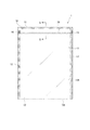
図1は、第一実施形態におけるジッパーテープ付袋体を示す正面図である。図2は、ジッパーテープ付袋体の図1中のII-IIの位置における断面図である。
Hereinafter, embodiments of the present invention will be described with reference to the drawings.
[First embodiment]
In 1st embodiment, the packaging bag for packaging various articles | goods, such as a foodstuff, a chemical | medical product, medical goods, miscellaneous goods, is illustrated as a bag body with a zipper tape.
FIG. 1 is a front view showing a bag body with a zipper tape in the first embodiment. FIG. 2 is a cross-sectional view of the bag body with a zipper tape at the position II-II in FIG.
(ジッパーテープ付袋体の構成)
図1,2に示すように、第一実施形態のジッパーテープ付袋体1は、袋本体10と、この袋本体10の内面に取り付けられたジッパーテープ20とを備えている。
袋本体10は、包材となるフィルムである基材フィルム11を二枚重ね合わせて、三方をシールして袋としたものである。この袋本体10は、周縁に一対のサイドシール部12およびトップシール部13が形成され、シールしていない一方(一辺)は、内部に被包装物を入れる投入口10Aが形成されている。そして、袋本体10の開口部14の内面にジッパーテープ20が取り付けられている。また、ジッパーテープ20の長手方向の両端におけるサイドシール部12の位置では、ジッパーテープ20が押し潰された潰し部16が形成されている。
なお、この袋本体10は、図示しない被包装物が袋本体10の投入口10Aから収納された後は、袋本体10の底辺をシールすることにより、密封状態とされる。
(Configuration of bag with zipper tape)
As shown in FIGS. 1 and 2, the bag body 1 with a zipper tape according to the first embodiment includes a
The
The
基材フィルム11は、直鎖状低密度ポリエチレン(LLDPE)、高密度ポリエチレン(HDPE)、未延伸ポリプロピレン(CPP)、ドライラミネート法や押出しラミネートで貼り合わされたラミネートフィルムとしてポリエチレンテレフタレート(PET)/LLDPE、PET/CPP、二軸延伸ポリプロピレン(OPP)/CPP、ナイロン/直鎖状低密度ポリエチレン(LLDPE)、金属または無機蒸着PET/LLDPEなどを挙げることができる。また、基材フィルム11としては、二軸延伸ポリプロピレン(OPP)で形成された外面側の外層に、未延伸ポリプロピレン(CPP)で形成されたシーラント層が積層された積層構造の他、直鎖状低密度ポリエチレン(LLDPE)、低密度ポリエチレン(LDPE)、高密度ポリエチレン(HDPE)などからなるシーラントと、ポリエチレンテレフタレート(PET)、ナイロン(ポリアミド)、金属または無機蒸着PETなどの基材とを、ドライラミネート法や押出ラミネート法で貼り合わされたラミネートフィルムを用いることができる。
The
ジッパーテープ20は、図2にその断面構成を示すように、対をなす雄部材21および雌部材22を備え、これら雄部材21と雌部材22とが、離隔または係合することにより、袋本体10の開口部14の開封または再封が行われることとなる。
雄部材21は、基材フィルム11に接合される接合部分である長手帯状の雄側帯状基部211と、雄側帯状基部211の一面で幅方向の略中央の位置に長手方向に沿って設けられ断面が略やじり形状の雄部212とを備えている。
雌部材22は、基材フィルム11に接合される接合部分である長手帯状の雌側帯状基部221と、雌側帯状基部221の一面で幅方向の略中央の位置に長手方向に沿って設けられ雄部212と係合する雌部222とを備えている。雄部212および雌部222により、係合部Sが構成される。
2, the
The
The
雄側帯状基部211は、雄部212に連続して一体的に形成される帯状の雄側基体部211Aと、雄側基体部211Aにおける雄部212が設けられた側と反対側の面に積層形成された吸光層23と、吸光層23に積層形成された接合層24とを備えた積層構造に形成されている。
雌側帯状基部221は、雌部222に連続して一体的に形成される帯状の雌側基体部221Aと、雌側基体部221Aにおける雌部222が設けられた側と反対側の面に積層形成された吸光層23と、吸光層23に積層形成された接合層24とを備えた積層構造に形成されている。
The male side belt-
The female-side belt-
ここで、雄部212および雄側基体部211Aと、雌部222および雌側基体部221Aとしては、エネルギー線としてのレーザー光X(図3参照)が照射されてもレーザー光Xを透過して溶融しにくい組成、すなわち少なくとも波長吸収域が800nm以上1200nm以下にない組成にて形成されていることが好ましい。具体的には、例えば、各種のポリエチレン、各種のポリプロピレン、ポリエチレンテレフタレート、二軸延伸ナイロンフィルム(ONy)、エチレン−ビニルアルコール共重合体などの樹脂を用いることができる。
特に、汎用のジッパーテープに主に使用されている点で、各種のポリエチレン、各種のポリプロピレンが好ましい。
Here, the
Particularly, various polyethylenes and various polypropylenes are preferable because they are mainly used for general-purpose zipper tapes.
また、吸光層23は、波長吸収域が800nm以上1200nm以下の吸光材料が樹脂組成物に含有されて形成されている。
そして、吸光材料としては、波長吸収域が800nm以上1200nm以下のレーザー光Xを吸収する有機系化合物および無機系化合物のうちの少なくともいずれか一方である。
有機系化合物としては、フタロシアニン系化合物、シアニン系化合物、アミニウム系化合物、イモニウム系化合物、スクオリウム系化合物、ポリメチン系化合物、アントラキノン系化合物、アゾ系化合物の群から選ばれる少なくともいずれか一種を用いることができる。
無機系化合物としては、金属の単体、金属塩、金属錯体、金属窒化物、金属酸化物、金属水酸化物の群から選ばれる少なくともいずれか一種を用いることができる。
特に、光をほぼ全吸収するカーボンブラックを用いることが好ましい。
また、吸光材料を含有する樹脂組成物としては、各種のポリエチレン、各種のポリプロピレン、ポリエチレンテレフタレート、二軸延伸ナイロンフィルム(ONy)、エチレン−ビニルアルコール共重合体などの樹脂を用いることができる。
特に、汎用のジッパーテープに主に使用されている点で、各種のポリエチレン、各種のポリプロピレンが好ましい。
The
And as a light absorption material, it is at least any one of the organic type compound and inorganic type compound which absorb the laser beam X whose wavelength absorption range is 800 nm or more and 1200 nm or less.
As the organic compound, it is possible to use at least one selected from the group of phthalocyanine compounds, cyanine compounds, aminium compounds, imonium compounds, squalium compounds, polymethine compounds, anthraquinone compounds, and azo compounds. it can.
As the inorganic compound, at least one selected from the group consisting of simple metals, metal salts, metal complexes, metal nitrides, metal oxides, and metal hydroxides can be used.
In particular, it is preferable to use carbon black that substantially absorbs light.
In addition, as the resin composition containing the light-absorbing material, resins such as various polyethylenes, various polypropylenes, polyethylene terephthalate, biaxially stretched nylon films (ONy), and ethylene-vinyl alcohol copolymers can be used.
Particularly, various polyethylenes and various polypropylenes are preferable because they are mainly used for general-purpose zipper tapes.
接合層24は、波長吸収域が800nm以上1200nm以下のレーザー光Xを透光可能な各種樹脂材料にて形成されている。この接合層24は、この接合層24を透過したレーザー光Xにより吸光層23が発熱することで溶融し、基材フィルム11に接合する。
接合層24に用いられる樹脂材料としては、例えば、融点が60℃以上120℃以下の低融点樹脂、具体的にはメタロセン触媒により生成されたメタロセン系オレフィンが好適に用いられる。より詳細には、例えば、密度が920kg/m3以下、メルトフローレート(MFR)が5g/10分以下のメタロセン系直鎖状低密度ポリエチレンを、接合層24全体に対して50質量%以上含有することが好ましく、より好ましくは50質量%以上99質量%以下含有し、70質量%以上99質量%以下とすることが特に好ましい。密度が920kg/m3を越える、あるいはMFRが5g/10分を越える直鎖状低密度ポリエチレンを50質量%以上含有した場合にあっては、基材フィルム11との接着性が悪く、当該基材フィルム11と接合しても手で簡単に剥離できる程度の接着強度となってしまう。特に、基材フィルム11がポリプロピレン系樹脂で構成された場合、良好に接合できないおそれがある。
かかるメタロセン系直鎖状低密度ポリエチレンの密度は、850kg/m3以上910kg/m3以下とすることが好ましく、特に、860kg/m3以上905kg/m3以下とすることが好ましい。また、MFRは、1g/10分以上5g/10分以下とすることが好ましい。
なお、密度はJIS K7121に準拠して、MFRはJIS K7210に準拠して(190℃、21.18N荷重)測定するようにすればよい。
The
As the resin material used for the
The density of such metallocene linear low density polyethylene is preferably in a 850 kg / m 3 or more 910 kg / m 3 or less, in particular, it is preferable that the 860 kg / m 3 or more 905 kg / m 3 or less. Moreover, it is preferable that MFR shall be 1 g / 10min or more and 5 g / 10min or less.
The density may be measured according to JIS K7121, and the MFR may be measured according to JIS K7210 (190 ° C., 21.18 N load).
一方、接合層24を構成する他の樹脂としては、前記した必須の構成材料である特定のメタロセン系直鎖状低密度ポリエチレンとの相溶性、または混合性が良好であり、かつ、基材フィルム11と良好な接着性を維持できるものであることが好ましく、例えば、密度が920kg/m3以下、メルトフローレート(MFR)が5.0g/10分を越えるメタロセン系直鎖状低密度ポリエチレン、MFR(190℃、21.18N荷重)が好ましくは0.5g/10分以上20g/10分以下のプロピレンと炭素数が4〜8のα−オレフィン共重合体、チーグラー系直鎖状低密度ポリエチレン、エチレン−極性ビニル共重合体などの樹脂を使用することができ、これらの一種を単独で、または二種以上を組み合わせて使用することができる。
On the other hand, the other resin constituting the
ここで、共押出成形によりジッパーテープ20を製造する場合、接合層24にメルトフローレート(MFR)が5g/10分以下のメタロセン系直鎖状低密度ポリエチレンのみを用いると、金型内で接合層24の樹脂が雄部212、雌部222に流れ込んでしまい、特に雌部222の各フック部の先端が閉じやすくなってしまったりするので、再開閉可能な所定の形状に押し出すことが困難となるおそれがある。接合層24を構成するMFRが5g/10分以下のメタロセン系直鎖状低密度ポリエチレンに、流動性の高い、MFRが5g/10分を越えるメタロセン系直鎖状低密度ポリエチレンや、プロピレンと炭素数4〜8のα−オレフィン共重合体を用いることにより、かかる雌部222などの形状崩れを防止することができる。
Here, when the
また、これらの樹脂の接合層24に対する含有量は、1質量%以上50質量%以下とすることが好ましく、5質量%以上40質量%以下とすることが特に好ましい。含有量が1質量%より小さいと、係合部Sの形状崩れを防止するといった効果を発揮することができない場合があり、含有量が50質量%より大きいと、低温シール性が損なわれる場合があるとともに、基材フィルム11との良好な接合性、特に基材フィルム11をポリプロピレン系樹脂とした場合における接合性が悪くなる場合があるため好ましくない。
Further, the content of these resins with respect to the
なお、これらの樹脂のうち、MFRが0.5g/10分以上20g/10分以下のプロピレンと炭素数が4〜8のα−オレフィン共重合体としてプロピレンとブテン−1との共重合体を使用すれば、前記した効果に加えて、接合層24と吸光層23との層間の接着強度が優れたものとなるため好ましい。ここで、当該共重合体のMFRは、1g/10分以上10g/10分以下であることがより好ましく、2g/10分以上8g/10分以下であることが特に好ましい。
Of these resins, a copolymer of propylene and butene-1 is used as an α-olefin copolymer having 4 to 8 carbon atoms and propylene having an MFR of 0.5 g / 10 min to 20 g / 10 min. If used, in addition to the effects described above, the adhesive strength between the
また、前記したように、接合層24を構成する樹脂として特定のメタロセン系直鎖状低密度ポリエチレン50質量%以上99質量%以下と、密度が920kg/m3以下、MFRが5.0g/10分を越えるメタロセン系直鎖状低密度ポリエチレンおよびプロピレンのうち一方と炭素数が4〜8のα−オレフィン共重合体を1質量%以上50質量%以下で使用し、吸光層23を構成する樹脂としてランダムポリプロピレンを使用すれば、共押出成形によりジッパーテープ20を製造した場合に接合層24と、吸光層23との流動性が均一となり、押出速度も略等しくすることができるため、吸光層23を構成するランダムポリプロピレンに余計なずり応力がかかることもなく、係合部Sにおける形状の崩れの発生をより一層好適に防止することができる。
As described above, the resin constituting the
そして、吸光層23として使用されるランダムポリプロピレン(RPP)は、エチレン成分を2.0質量%以上8.0質量%以下で含有することが好ましく、3.0質量%以上6.0質量%以下で含有することが特に好ましい。ランダムポリプロピレンに対して含有されるエチレン成分が2.0質量%より小さいと、係合部Sの再開閉性が悪くなる場合があり、一方、エチレン成分が8.0質量%より大きいと、接合層24に主に利用されるメタロセン系直鎖状低密度ポリエチレンを使用した場合、吸光層23のランダムポリプロピレンのエチレン量が多くなると、接合層24と同じ組成が増えていくこととなる。このことにより、融点も下がるので、接合層24との融点差が小さくなり、ジッパーテープ20の接合が煩雑となるおそれがある。
And it is preferable that the random polypropylene (RPP) used as the
また、このランダムポリプロピレン(RPP)のメルトフローレート(MFR)は、3g/10分以上10g/10分以下であることが好ましく、5g/10分以上9g/10分以下であることが特に好ましい。ランダムポリプロピレンのMFRが3g/10分より小さいと、吸光層23と、雄側基体部211Aおよび雄部212、または、雌側基体部221Aおよび雌部222とを連続して一体的に形成される係合部Sの押出成形性が悪くなる場合があり、一方、MFRが10g/10分より大きいと、雌部222の各フック部の先端が閉じやすくなったり、雄部212が倒れやすくなったりするので、再開閉可能な所定の形状に押し出すことが困難になる場合がある。
Further, the melt flow rate (MFR) of this random polypropylene (RPP) is preferably 3 g / 10 min or more and 10 g / 10 min or less, particularly preferably 5 g / 10 min or more and 9 g / 10 min or less. When the MFR of random polypropylene is smaller than 3 g / 10 min, the
そして、吸光層23および雄側基体部211Aまたは雌側基体部221Aは、接合層24と共押出成形法により一体化して得ることができる。ジッパーテープ20をこのような共押出法により成形すれば、ジッパーテープ20を連続的に安定して製造することができる。
And the
なお、ジッパーテープ付袋体1の開封位置は、雄部212および雌部222にて構成される係合部Sの位置よりも開口側であればよく、基材フィルム11にノッチを入れたり、雄部212または雌部222近傍に開封テープを設けたりすることで、開けやすくすることもできる。
In addition, the opening position of the bag body 1 with a zipper tape should just be an opening side rather than the position of the engaging part S comprised by the
(ジッパーテープ付袋体の製造装置)
次に、シッパーテープ付袋体の製造装置について説明する。
図3は、ジッパーテープ付袋体の製造装置を示す概念図である。図4は、ジッパーテープ付袋体を製造する接合工程を示す説明図である。
(Manufacturing device for bags with zipper tape)
Next, the manufacturing apparatus of a bag body with a sipper tape will be described.
FIG. 3 is a conceptual diagram showing an apparatus for manufacturing a bag body with a zipper tape. FIG. 4 is an explanatory view showing a joining process for manufacturing a bag body with a zipper tape.
図3に示すように、製造装置30は、繰出ロール31、32、33と、四台のレーザー照射装置34と、対をなす圧着ローラ35と、潰し形成装置36と、サイドシール形成装置37と、トップシール形成装置38と、などを備えている。
As shown in FIG. 3, the
ここで、レーザー照射装置34としては、ジッパーテープ20の吸光層23で吸光され、接合層24を溶融可能ないずれのものを利用できる。例えば、ダイオードレーザーやYAGレーザーなどの固体レーザー、色素レーザーなどの液体レーザー、CO2レーザーなどのガスレーザーを利用できる。特に、連続的にレーザー光Xを照射して接合層24を溶融可能な構成が好ましい。
そして、レーザー照射装置34は、四台のうちの二台が雄側帯状基部211の長手方向の両側にそれぞれレーザー光Xを照射し、残りの二台が雌側帯状基部221の長手方向の両側にそれぞれレーザー光Xを照射するようになっている。
また、レーザー照射装置34は、レーザー光Xを接合層24の平面に入射角θが0°より大きく90°以下、好ましくは接合層24の平面に対して交差する入射角θが45°以上85°以下となるように配置されている。特に、45°より小さい入射角θになるとレーザー光Xの照射エネルギーを吸光層23に効率よく供給できなくなるおそれがある。また、85°より大きくなると、レーザー照射装置34と製造装置30の他の構成との干渉により、レーザー光Xの照射後から圧着ローラ35にて接合層24を基材フィルム11に圧着させるまでに時間を要し、溶融した接合層24が冷却固化し始めて十分な接合が得られなくなるおそれがあるためである。
すなわち、レーザー光Xを照射して接合層24を溶融してから、接合層24が冷却固化する前に、速やかに基材フィルム11に圧着するように、レーザー照射装置34を配置する必要がある。
Here, as the
In the
Further, the
That is, it is necessary to arrange the
また、圧着ローラ35の間には、図4に示すように、係合するジッパーテープ20の雄部212および雌部222との厚さ寸法分の一対のスペーサー39が、係合する雄部212および雌部222の幅寸法分程度の隙間を介して配置されている。
すなわち、圧着ローラ35にて二枚の基材フィルム11間に介在するジッパーテープ20を押圧する際、基材フィルム11が雄側帯状基部211や雌側帯状基部221と十分に圧着するようになっている。
なお、圧着する構成としては、圧着ローラ35の他、例えば無端ベルトにて圧着したり、押圧バーにて押し付けたりする各種構成を適用できる。
As shown in FIG. 4, a pair of
That is, when the
In addition to the
(ジッパーテープ付袋体の製造方法)
次に、ジッパーテープ付袋体の製造方法について説明する。
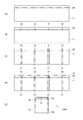
図5は、ジッパーテープ付袋体を製造する工程を示す説明図で、(A)はジッパーテープを基材フィルムに取り付けた状態を示す平面図、(B)はつぶしを形成した状態を示す平面図、(C)はサイドシール部を形成した状態を示す平面図、(D)はトップシール部を形成した状態を示す平面図、(E)はジッパーテープ付袋体を示す平面図である。
(Manufacturing method of bag with zipper tape)
Next, the manufacturing method of a bag body with a zipper tape is demonstrated.
FIG. 5 is an explanatory view showing a process of manufacturing a bag body with a zipper tape, (A) is a plan view showing a state in which the zipper tape is attached to a base film, and (B) is a plan view showing a state in which crushing is formed. (C) is a top view which shows the state which formed the side seal part, (D) is a top view which shows the state which formed the top seal part, (E) is a top view which shows a bag body with a zipper tape.
まず、図3に示す製造装置30の繰出ロール31、32は、基材フィルム11が予め巻装され、基材フィルム11を互いに対向する状態に送り出す。
また、繰出ロール33は、予め雄部材21および雌部材22が係合されたジッパーテープ20が巻装され、二枚の基材フィルム11間に送り出す。
First, the feeding rolls 31 and 32 of the
The feeding
そして、ジッパーテープ20が圧着ローラ35間に挟み込まれる直前に、レーザー照射装置34により、ジッパーテープ20の接合層24の長手方向の両側にそれぞれ同時にレーザー光Xを照射する。このレーザー光Xの照射により、接合層24を透過し吸光層23に到達したレーザー光Xは、吸光層23を発熱させ、この熱により接合層24を幅方向で略均一に溶融させる照射工程が実施される。
この照射工程により接合層24が溶融された後、直ちに、圧着ローラ35により基材フィルム11間にジッパーテープ20を挟み込むようにして、溶融する接合層24を基材フィルム11に圧着させる接合工程を実施する。なお、圧着ローラ35にて基材フィルム11に圧着されている状態で、接合層24は次第に冷却固化され、基材フィルム11に強固に接合される。この接合工程により、図5(A)に示すように、ジッパーテープ20は基材フィルム11間に取り付けられる。
Then, immediately before the
Immediately after the joining
この後、図5(B)に示すように、潰し形成装置56により、基材フィルム11に取り付けられたジッパーテープ20を、所定間隔で加熱して潰して潰し部16を形成する。
そして、図5(C)に示すように、サイドシール形成装置37により、潰し部16の位置毎に、基材フィルム11の繰出方向となる長手方向に対して垂直な方向に、サイドシール部12となるサイド区画部17を形成する。
この後、図5(D)に示すように、トップシール形成装置58により、トップシール部13となるトップ区画部19を形成する。
そして、基材フィルム11をサイド区画部17の中心線に沿って切断することにより、図5(E)に示すように、投入口10Aを開口するジッパーテープ付袋体1が得られる。
Thereafter, as shown in FIG. 5 (B), the crushing forming device 56 heats and crushes the
And as shown in FIG.5 (C), the side seal |
Thereafter, as shown in FIG. 5D, the
And the
(第一実施形態の効果)
上述したように、上記第一実施形態では、波長吸収域が800nm以上1200nm以下のレーザー光Xを吸光する吸光材料を含有する吸光層23を設けている。
このため、吸光材料が効率よくレーザー光Xを吸収して加熱させ、吸光層23に隣接する低融点樹脂を含有する接合層24のみを接合させることができる。したがって、ジッパーテープ20を取り付ける基材フィルム11などの熱劣化が生じることを抑制でき、製造するジッパーテープ付袋体1の歩留まりが悪化することを防止できる。さらに、ジッパーテープ20のみにレーザー光Xを照射することにより、レーザー光Xのエネルギーを接合層24の溶融に効率よく利用でき、エネルギー効率を向上できる。また、デジタル信号のレーザー光Xにより接合層24のみ溶融させるので、接合層24の溶融および基材フィルム11との接合が速やかに実施でき、製袋速度を速くすることが可能となり、製袋効率を向上できる。
具体的には、図6に示すように、吸光層23および接合層24を一つの吸光接合層25として構成したものでも、接合できることを確認できた。すなわち、カーボンブラックを、融点95℃、MFR4.0g/10分のメタロセン系直鎖状低密度ポリエチレンに1:99の割合で混合して厚さ25μmの吸光接合層25を形成した。そして、波長1.07μmのファイバーレーザーにより、ジッパーテープ20のライン速度60m/分(ピッチ100mm=600ショット)で接合できることを確認できた。
(Effects of the first embodiment)
As described above, in the first embodiment, the light-absorbing
For this reason, the light absorbing material can efficiently absorb and heat the laser beam X, and only the
Specifically, as shown in FIG. 6, it was confirmed that even the
そして、上記第一実施形態では、波長吸収域が800nm以上1200nm以下のレーザー光Xを吸光する吸光材料を用いるので、吸光材料が効率よくレーザー光Xを吸収し、吸光層23に隣接する低融点樹脂を含有する接合層24のみを溶融することができる。
このため、ジッパーテープ20を取り付ける基材フィルム11などの熱劣化が生じることを抑制でき、良好に接着できる。
And in said 1st embodiment, since the light absorption material which absorbs the laser beam X whose wavelength absorption region is 800 nm or more and 1200 nm or less is used, the light absorption material absorbs the laser beam X efficiently, and the low melting point adjacent to the
For this reason, it can suppress that thermal deterioration of the
特に、接合層24として、融点が60℃以上120℃以下の低融点樹脂、具体的には、メタロセン触媒により生成されたメタロセン系オレフィン、特にメタロセン系直鎖状低密度ポリエチレンを用いている。
このため、レーザー光Xの照射により吸光層23の吸光材料が吸光して生じる熱エネルギーを、隣接する接合層24の低融点樹脂の溶融に直接的に作用でき、レーザー光Xの照射エネルギーを効率よくジッパーテープ20の取付に利用できる。
In particular, as the
For this reason, the heat energy generated by the absorption of the light absorbing material of the
また、上記第一実施形態では、吸光層23に接合層24を積層して、レーザー光Xの照射により加熱した吸光層23が隣接する接合層24を溶融させるので、接合層24全体を均一に溶融でき、良好に基材フィルム11に接合できる。さらに、溶融して基材フィルム11に接合する接合層24には吸光材料が含まれていないので、基材フィルム11との接合性が吸光材料に損なわれることも防止でき、良好な接合性が得られる。
In the first embodiment, the
さらに、上記第一実施形態では、雄部212および雄側基体部211Aと、雌部222および雌側基体部221Aと、吸光層23としては、800nm以上1200nm以下の波長に吸収を示さない樹脂を用いて形成している。
このため、レーザー光Xの照射により溶融して変形してしまう不都合を防止できる。
Furthermore, in the first embodiment, the
For this reason, the inconvenience which melt | dissolves and deform | transforms by irradiation of the laser beam X can be prevented.
[第二実施形態]
次に、本発明の第二実施形態について図面を参照して説明する。
第二実施形態では、1枚の基材フィルム11を用いて製袋されたものである。なお、第一実施形態と同一もしくは同等の構成については、同一の符号を付して説明を省略または簡略化する。
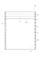
図7は、第二実施形態におけるジッパーテープ付袋体を示す正面図である。図8は、ジッパーテープ付袋体のジッパーテープ近傍を示す断面図である。
[Second Embodiment]
Next, a second embodiment of the present invention will be described with reference to the drawings.
In the second embodiment, the bag is made using one
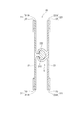
FIG. 7 is a front view showing a bag body with a zipper tape in the second embodiment. FIG. 8 is a cross-sectional view showing the vicinity of a zipper tape of a bag body with a zipper tape.
(ジッパーテープ付袋体の構成)
図7,8に示すように、ジッパーテープ付袋体40は、袋本体41の内面に、ジッパーテープ20が取り付けられている。
袋本体41は、基材フィルム11の一方の基材端部11Aが他方の基材端部11Aに重ね合わされたシール部15を有している。また、基材フィルム11の両側端部には、互いの基材フィルム11がヒートシールされたサイドシール部12が設けられている。このサイドシール部12には、ジッパーテープ20の長手方向の両端部がヒートシールされている。
袋本体41には、シール部15およびサイドシール部12により収納空間10Bが形成されている。この収納空間10Bには、粉体などの固体や液体を収納可能である。
また、袋本体41の底部には、ガゼット18が形成されている。
(Configuration of bag with zipper tape)
As shown in FIGS. 7 and 8, the zipper tape-attached
The
A
A
(ジッパーテープ付袋体の製造装置)
次に、ジッパーテープ付袋体の製造装置について説明する。
図9は、ジッパーテープ付袋体の製造装置を示す斜視図である。図10は、ジッパーテープ付袋体の製造装置におけるジッパーテープを基材フィルムに接合する接合装置を示す斜視図である。図11は、図10の接合装置を示す側面図である。なお、図9,10は、都合上、雄部材21および雌部材22のうちの一方のみ記載し他方を省略する。
(Manufacturing device for bags with zipper tape)
Next, the manufacturing apparatus of a bag body with a zipper tape is demonstrated.
FIG. 9 is a perspective view showing an apparatus for manufacturing a bag body with a zipper tape. FIG. 10: is a perspective view which shows the joining apparatus which joins the zipper tape in a manufacturing apparatus of a bag body with a zipper tape to a base film. FIG. 11 is a side view showing the joining apparatus of FIG. 9 and 10, for convenience, only one of the
図9に示すように、製造装置50は、接合装置51と、製袋装置52とを備えている。
接合装置51は、咬合していない一対の雄部材21および雌部材22をそれぞれ供給するテープ巻取ロール511(一方のみ図示)と、基材フィルム11を供給する図示しないフィルム巻取ロールと、図示省略の駆動源によって回転される回転ドラム512と、供給される雄部材21および雌部材22を回転ドラム512の周面にそれぞれ導入する導入ローラ513と、レーザー照射装置514と、圧着ローラ515と、などを備えている。
As shown in FIG. 9, the
The joining
回転ドラム512の周面には、周方向に沿って凹溝状に形成され雄部材21および雌部材22がそれぞれ挿入される導入溝512A(一方のみ図示)が設けられている。なお、導入溝512Aは、設けなくてもよい。
導入溝512Aは、導入ローラ513により挿入された雄部材21または雌部材22の接合層24の表面が回転ドラム512の周面と略同一面上に位置する深さに形成されている。
The circumferential surface of the
The
レーザー照射装置514は、図11に示すように、レーザー光Xを接合層24の表面の垂線に対して斜めに交差するように照射する。具体的には、回転ドラム512の周面の接線方向に対して入射角θが0°より大きく90°以下、好ましくは入射角θが45°以上85°以下となるように配置されている。特に、45°より小さい入射角θになるとレーザー光Xの照射エネルギーを吸光層23に効率よく供給できなくなるおそれがあり、85°より大きくなると、レーザー照射装置514と製造装置50の他の構成との干渉により、レーザー光Xの照射後から圧着ローラ515にて接合層24を基材フィルム11に圧着させるまでに時間を要し、溶融した接合層24が冷却固化し始めて十分な接合が得られなくなるおそれがあるためである。
なお、レーザー照射装置514は、例えば4台配置し、接合層24の長手方向における両側部分にそれぞれレーザー光Xを照射するようにしてもよい。このことにより、接合層24全体を均一に溶融させることが容易にできるとともに、接合層24を溶融させる時間をより短縮でき、ジッパーテープ20をより短時間で基材フィルム11に接合させることができる。
As shown in FIG. 11, the
For example, four
一対の圧着ローラ515は、回転ドラム512の周面に基材フィルム11を導入させ、回転ドラム512の回転に伴って連続走行させ、回転ドラム512の周面に圧着させる。これら圧着ローラ515により、雄部材21および雌部材22の溶融された接合層24と導入された基材フィルム11とが圧着されて接合される。
なお、一対の圧着ローラ515は、例えば、導入する基材フィルム11を回転ドラム512の周面に直接圧着させるように配置してもよい。
The pair of
In addition, you may arrange | position a pair of
製袋装置52は、図9に示すように、一対の爪潰バー521と、ジッパーテープ20が接合された基材フィルム11が巻かれる円筒フォーマ522と、この円筒フォーマ522の側部に配設された送りベルト523と、基材フィルム11の両基材端部11Aを接合してシール部15を形成するシールバー524と、サイドシール部12を形成するサイドシールバー525と、ガゼット18を形成する三角板526とを備える。
一対の爪潰バー521は、雄部材21および雌部材22を挟んで対向配置されている。そして、所定の間隔ごとに、各爪潰バー521が雄部材21および雌部材22を押潰して溶融扁平化する。溶融扁平化された図示しない爪潰部は、ジッパーテープ付袋体40のサイドシール部12に対応する位置に形成される。
円筒フォーマ522は、中空に形成され、内部空間を通して、ジッパーテープ付袋体40に収納物を充填する。
As shown in FIG. 9, the
The pair of
The cylindrical former 522 is formed in a hollow shape, and fills the
(ジッパーテープ付袋体の製造方法)
次に、ジッパーテープ付袋体の製造方法について説明する。
この製造方法では、接合装置51により、雄部材21および雌部材22にそれぞれレーザー光Xを照射して溶融させる照射工程、および、接合層24が溶融された雄部材21および雌部材22に基材フィルム11を圧着して接合させる接合工程と、製袋装置52により、雄部材21および雌部材22が取り付けられた基材フィルム11を使って製袋する製袋工程と、を実施する。
テープ巻取ロール511からそれぞれ引き出された雄部材21および雌部材22は、接合装置51の導入ローラ513により回転ドラム512の周面に保持、すなわち回転ドラム512の導入溝512A内を通りながら、回転ドラム512の回転により連続走行される。なお、回転ドラム512は連続回転に限らず、間欠回転としてもよい。
そして、基材フィルム11が供給される位置の前に、レーザー照射装置514により、雄部材21および雌部材22の接合層24にレーザー光Xを照射し、接合層24を幅方向で略均一に溶融させる照射工程が実施される。
この照射工程により接合層24が溶融された後、直ちに、圧着ローラ515により基材フィルム11を回転ドラム512の周面に導入して雄部材21および雌部材22に圧着させて接合させる接合工程が実施される。
(Manufacturing method of bag with zipper tape)
Next, the manufacturing method of a bag body with a zipper tape is demonstrated.
In this manufacturing method, the joining
The
Then, before the position where the
Immediately after the
このようにして、雄部材21および雌部材22が接合された基材フィルム11は、製袋装置52に送られ、爪潰バー521により、雄部材21および雌部材22に爪潰部が形成される。
この後、基材フィルム11は、円筒フォーマ522に巻かれつつ、送りベルト523によって下方に送られる。ここで、爪潰部とサイドシール部12とが一致するように送られる。そして、シールバー524によりシール部15が形成されつつ、三角板526により、底に対応する部分にガゼット18を形成する。
また、サイドシールバー525により一方のサイドシール部12が形成される。そして、円筒フォーマ522の内部空間を通して収納物の充填を行った後、再びサイドシールバー525により他方のサイドシール部12を形成する。そして、ジッパーテープ付袋体40の切り離しを行う。
In this way, the
Thereafter, the
Further, one
(第二実施形態の効果)
上述した第二実施形態のような製袋方法でも、第一実施形態と同様の効果を奏する。
また、第二実施形態では、回転ドラム512を用いるため、製造装置50の他の部位との干渉が生じることなくレーザー光Xを雄部材21および雌部材22の接合層24に照射でき、製造装置50の製造が容易にできる。
(Effect of the second embodiment)
Even with the bag making method as in the second embodiment described above, the same effects as in the first embodiment can be obtained.
Further, in the second embodiment, since the
[変形例]
なお、本発明を実施するための最良の構成などは、以上の記載で開示されているが、本発明は、これに限定されるものではない。すなわち、本発明は、主に特定の実施形態に関して説明されているが、本発明の技術的思想および目的の範囲から逸脱することなく、以上述べた実施形態に対し、材質、数量、その他の詳細な構成において、当業者が様々な変形を加えることができるものである。
したがって、上記に開示した材質、層構成などを限定した記載は、本発明の理解を容易にするために例示的に記載したものであり、本発明を限定するものではないから、それらの材質などの限定の一部若しくは全部の限定を外した名称での記載は、本発明に含まれるものである。
[Modification]
Although the best configuration for carrying out the present invention has been disclosed in the above description, the present invention is not limited to this. That is, the present invention has been described primarily with reference to specific embodiments, but with respect to the above-described embodiments without departing from the scope of the technical idea and object of the present invention, the material, quantity, and other details. In this configuration, those skilled in the art can make various modifications.
Accordingly, the description of the materials, layer structures, and the like disclosed above is exemplary for easy understanding of the present invention, and does not limit the present invention. Descriptions with names excluding some or all of the limitations are included in the present invention.
例えば、第一実施形態において、雄側帯状基部211および雌側帯状基部221の包装を積層構造としたが、いずれか一方のみを積層構造としたものとしてもよい。
そして、積層構造としては、例えば図12に示すように、雄側帯状基部211および雌側帯状基部221における基材フィルム11と接合させる幅方向の両側部分のみに形成してもよい。さらには、雄側帯状基部211および雌側帯状基部221が長手方向で波形状に蛇行する形状で形成したり、複数のドット状に形成したりしてもよい。
また、積層構造として、例えば図13に示すように、接合層24を設けず、吸光接合層25のように、吸光層23を所定の融点(60℃以上120℃以下)の樹脂が含有されたものとし、この吸光層23のみを積層させた構成としてもよい。
さらには、雄側帯状基部211および雌側帯状基部221の一方を、吸光層23および接合層24が設けられた積層構造で、他方を所定の融点の樹脂が含有された吸光層23のみが設けられた積層構造として、異なる積層構造となるようにしてもよい。
For example, in the first embodiment, the packaging of the male side belt-
And as a laminated structure, as shown, for example in FIG. 12, you may form only in the both sides of the width direction joined to the
Further, as shown in FIG. 13, for example, as shown in FIG. 13, the light-absorbing
Furthermore, one of the male side belt-
また、吸光層23および接合層24を設けず、雄側帯状基部211および雌側帯状基部221に、波長吸収域が800nm以上1200nm以下の吸光材料を含有させてもよい。この構成では、特に係合部Sには吸光材料が含有されない構成とすることが好ましい。すなわち、係合部Sにレーザー光Xが照射されて係合部Sが変形してしまうなどの不都合を確実に防止するためである。
なお、係合部Sに吸光材料が含有されていても、レーザー光Xが照射されないようにしておけばよい。
In addition, the
Even if the light-absorbing material is contained in the engaging portion S, the laser beam X may be prevented from being irradiated.
また、溶融させる部分に用いる所定の融点の樹脂としては、60℃以上120℃以下のいずれの樹脂を用いることができ、さらにこの温度範囲以外の樹脂材料を用いてもよい。 Moreover, as resin of the predetermined | prescribed melting | fusing point used for the part to fuse | melt, any resin of 60 degreeC or more and 120 degrees C or less can be used, Furthermore, you may use resin materials other than this temperature range.
第二実施形態において、一対の雄部材21および雌部材22をそれぞれ取り付ける構成を例示したが、例えば雄部材21および雌部材22が並列に一体に設けられ、中央に折曲のための折曲部を有したジッパーテープ部材を用いて一体のまま基材フィルム11に取り付けるなどしてもよい。
本発明は、第一実施形態および第二実施形態の他、さらに各種の製袋方法でも適用できる。
In 2nd embodiment, although the structure which attaches a pair of
The present invention can be applied to various bag making methods in addition to the first embodiment and the second embodiment.
また、レーザー光Xをジッパーテープ20に垂直に照射してもよい。
そして、ジッパーテープ20の両側にそれぞれレーザー光Xを照射する場合に限らず、幅方向における中央部分や全域に照射してもよい。また、幅方向でスキャンするように照射して全体を溶融させるようにしてもよい。そして、雄部材21および雌部材22に同時にレーザー光Xを照射する他、同時でなく、例えば交互に照射したり、片側ずつ照射したりしてもよい。
Further, the
And not only when irradiating the laser beam X to both sides of the
1,40…ジッパーテープ付袋体
10,41…袋本体
11…フィルムである基材フィルム
20…ジッパーテープ
21…雄部材
22…雌部材
23…吸光層
24…接合層
211…雄側帯状基部
212…雄部
221…雌側帯状基部
222…雌部
X…エネルギー線であるレーザー光
DESCRIPTION OF
Claims (9)
少なくとも一部に、波長吸収域が800nm以上1200nm以下の吸光材料が含有された
ことを特徴とするジッパーテープ。 A zipper tape comprising a male member and a female member making a pair,
A zipper tape, wherein a light absorbing material having a wavelength absorption range of 800 nm or more and 1200 nm or less is contained at least in part.
前記吸光材料は、フタロシアニン系化合物、シアニン系化合物、アミニウム系化合物、イモニウム系化合物、スクオリウム系化合物、ポリメチン系化合物、アントラキノン系化合物、アゾ系化合物のうちの少なくともいずれか1種の有機系化合物と、カーボンブラック、金属の単体、塩、錯体、窒化物、酸化物、水酸化物のうちの少なくともいずれか1種の無機系化合物とのうち、少なくともいずれか一方である
ことを特徴とするジッパーテープ。 The zipper tape according to claim 1,
The light-absorbing material includes at least one organic compound selected from a phthalocyanine compound, a cyanine compound, an aminium compound, an imonium compound, a squalium compound, a polymethine compound, an anthraquinone compound, and an azo compound; A zipper tape, characterized in that it is at least one of carbon black, a simple substance of metal, a salt, a complex, a nitride, an oxide, and a hydroxide.
前記雄部材は、少なくとも2層以上の積層構造であって、雄側帯状基部および前記雄側帯状基部の一面に設けられた雄部を備え、
前記雌部材は、少なくとも2層以上の積層構造であって、雌側帯状基部および前記雌側帯状基部の一面に設けられ前記雄部と係合可能な雌部を備え、
前記雄側帯状基部および前記雌側帯状基部の少なくともいずれか一方には、前記吸光材料が含有された吸光層が、少なくとも前記雄部および前記雌部が設けられる一面の表面層以外の少なくとも1層に設けられた
ことを特徴とするジッパーテープ。 The zipper tape according to claim 1 or 2,
The male member has a laminated structure of at least two layers, and includes a male side belt-like base and a male part provided on one surface of the male side belt-like base,
The female member has a laminated structure of at least two layers, and includes a female side belt-like base portion and a female portion that is provided on one surface of the female side belt-like base portion and can be engaged with the male portion,
At least one of the male side band-shaped base and the female side band-shaped base has at least one light-absorbing layer containing the light-absorbing material, except at least one surface layer on which the male part and the female part are provided. The zipper tape characterized by being provided in.
前記雄部材は、少なくとも3層以上の積層構造であって、雄側帯状基部および前記雄側帯状基部の一面に設けられた雄部を備え、
前記雌部材は、少なくとも3層以上の積層構造であって、雌側帯状基部および前記雌側帯状基部の一面に設けられ前記雄部と係合可能な雌部を備え、
前記雄側帯状基部および前記雌側帯状基部の少なくともいずれか一方は、前記雄部および前記雌部が設けられる一面と反対側の面に臨んで設けられ、融点が60℃以上120℃以下の樹脂を含有する接合層と、前記接合層に隣接して、前記吸光材料が含有された吸光層とを備えた
ことを特徴とするジッパーテープ。 The zipper tape according to claim 1 or 2,
The male member has a laminated structure of at least three layers, and includes a male side belt-like base and a male part provided on one surface of the male side belt-like base,
The female member has a laminated structure of at least three layers, and includes a female side belt-like base portion and a female portion that is provided on one surface of the female side belt-like base portion and can be engaged with the male portion,
Resin having a melting point of 60 ° C. or higher and 120 ° C. or lower, at least one of the male side belt-like base portion and the female side belt-like base portion facing the surface opposite to the one surface on which the male portion and the female portion are provided. And a light-absorbing layer containing the light-absorbing material adjacent to the bonding layer.
前記雄部および前記雌部の少なくともいずれか一方は、800nm以上1200nm以下の波長に吸収を示さない樹脂により形成された
ことを特徴とするジッパーテープ。 The zipper tape according to claim 3 or 4,
At least one of the male part and the female part is formed of a resin that does not absorb light at a wavelength of 800 nm or more and 1200 nm or less.
前記吸光材料が含有される部分は、融点が60℃以上120℃以下の樹脂が含有されている
ことを特徴とするジッパーテープ。 In the zipper tape according to any one of claims 1 to 5,
The portion containing the light-absorbing material contains a resin having a melting point of 60 ° C. or higher and 120 ° C. or lower.
前記樹脂は、メタロセン触媒により生成されたメタロセン系オレフィンを主成分とする
ことを特徴とするジッパーテープ。 The zipper tape according to claim 4 or 6,
The zipper tape characterized in that the resin is mainly composed of a metallocene olefin produced by a metallocene catalyst.
この袋本体の内面に取り付けられた請求項1から請求項7までのいずれか一項に記載のジッパーテープと、
を具備したことを特徴とするジッパーテープ付袋体。 A bag body overlaid with films;
The zipper tape according to any one of claims 1 to 7, attached to the inner surface of the bag body,
A bag body with a zipper tape, comprising:
前記ジッパーテープに800nm以上1200nm以下のエネルギー線を照射する照射工程と、
前記照射工程で溶融された前記ジッパーテープの前記エネルギー線が照射された部分に前記フィルムを圧着させる接合工程と、を実施する
ことを特徴とするジッパーテープ付袋体の製造方法。 A manufacturing method for manufacturing a bag body with a zipper tape by attaching the zipper tape according to any one of claims 1 to 7 to a film,
An irradiation step of irradiating the zipper tape with energy rays of 800 nm to 1200 nm;
A bonding step in which the film is pressure-bonded to a portion of the zipper tape melted in the irradiation step that has been irradiated with the energy ray. A method for producing a bag body with a zipper tape.
Priority Applications (9)
| Application Number | Priority Date | Filing Date | Title |
|---|---|---|---|
| JP2015079633A JP2016198218A (en) | 2015-04-08 | 2015-04-08 | Zipper tape, bag body with zipper tape, and method for manufacturing bag body with zipper tape |
| US15/565,073 US11370064B2 (en) | 2015-04-08 | 2016-04-07 | Zipper tape, bag with zipper tape, method for manufacturing bag with zipper tape, long member-bonding method capable of favorably bonding long members, device therefor, and zipper tape-bonding device |
| PCT/JP2016/061459 WO2016163487A1 (en) | 2015-04-08 | 2016-04-07 | Zipper tape, bag with zipper tape, method for manufacturing bag with zipper tape, long member-bonding method capable of favorably bonding long members, device therefor, and zipper tape-bonding device |
| CN201680020170.3A CN107428089B (en) | 2015-04-08 | 2016-04-07 | Zipper tape and its jointing device, bag body with zipper tape and its manufacturing method |
| CN202011219720.9A CN112389843B (en) | 2015-04-08 | 2016-04-07 | Zipper tape, bag body with zipper tape and manufacturing method of bag body |
| KR1020177031869A KR102449936B1 (en) | 2015-04-08 | 2016-04-07 | A method for manufacturing a zipper tape, a bag body having a zipper tape, and a bag body having a zipper tape, a method for joining an elongated member capable of bonding the elongated member satisfactorily, an apparatus therefor, and an apparatus for bonding a zipper tape |
| EP16776653.4A EP3281773B1 (en) | 2015-04-08 | 2016-04-07 | Zipper tape, bag with zipper tape, method for manufacturing bag with zipper tape |
| TW105111139A TWI681907B (en) | 2015-04-08 | 2016-04-08 | Clip belt, bag body with clip chain belt, and method for manufacturing bag body with clip chain belt, and method for joining elongated members that can be well-joined with elongated members, device thereof, and device for joining straps |
| JP2019201472A JP6941653B2 (en) | 2015-04-08 | 2019-11-06 | Manufacturing method of bag with zipper tape |
Applications Claiming Priority (1)
| Application Number | Priority Date | Filing Date | Title |
|---|---|---|---|
| JP2015079633A JP2016198218A (en) | 2015-04-08 | 2015-04-08 | Zipper tape, bag body with zipper tape, and method for manufacturing bag body with zipper tape |
Related Child Applications (1)
| Application Number | Title | Priority Date | Filing Date |
|---|---|---|---|
| JP2019201472A Division JP6941653B2 (en) | 2015-04-08 | 2019-11-06 | Manufacturing method of bag with zipper tape |
Publications (1)
| Publication Number | Publication Date |
|---|---|
| JP2016198218A true JP2016198218A (en) | 2016-12-01 |
Family
ID=57423652
Family Applications (1)
| Application Number | Title | Priority Date | Filing Date |
|---|---|---|---|
| JP2015079633A Pending JP2016198218A (en) | 2015-04-08 | 2015-04-08 | Zipper tape, bag body with zipper tape, and method for manufacturing bag body with zipper tape |
Country Status (1)
| Country | Link |
|---|---|
| JP (1) | JP2016198218A (en) |
Cited By (3)
| Publication number | Priority date | Publication date | Assignee | Title |
|---|---|---|---|---|
| JPWO2019097942A1 (en) * | 2017-11-14 | 2019-12-19 | トタニ技研工業株式会社 | Welding method and welding device |
| JP2022032312A (en) * | 2020-08-11 | 2022-02-25 | 朋和産業株式会社 | Packaging bag with fastener and manufacturing method of the same |
| WO2022064860A1 (en) | 2020-09-25 | 2022-03-31 | トタニ技研工業株式会社 | Bag-making machine |
Citations (6)
| Publication number | Priority date | Publication date | Assignee | Title |
|---|---|---|---|---|
| JPH02152662A (en) * | 1988-11-29 | 1990-06-12 | Idemitsu Petrochem Co Ltd | Fastener and packing bag with fastener |
| JP2002526261A (en) * | 1998-10-01 | 2002-08-20 | ザ ウェルディング インスティチュート | Welding method |
| US20070051461A1 (en) * | 2004-06-24 | 2007-03-08 | Wilhelm Pfleging | Method for joining plastic work pieces |
| JP2010146791A (en) * | 2008-12-17 | 2010-07-01 | Yazaki Corp | Flat circuit body |
| JPWO2009022739A1 (en) * | 2007-08-16 | 2010-11-18 | 味の素株式会社 | Plastic film welding method and drug bag |
| WO2014166506A1 (en) * | 2013-04-11 | 2014-10-16 | Københavns Universitet | A method for laser welding of plastic materials |
-
2015
- 2015-04-08 JP JP2015079633A patent/JP2016198218A/en active Pending
Patent Citations (6)
| Publication number | Priority date | Publication date | Assignee | Title |
|---|---|---|---|---|
| JPH02152662A (en) * | 1988-11-29 | 1990-06-12 | Idemitsu Petrochem Co Ltd | Fastener and packing bag with fastener |
| JP2002526261A (en) * | 1998-10-01 | 2002-08-20 | ザ ウェルディング インスティチュート | Welding method |
| US20070051461A1 (en) * | 2004-06-24 | 2007-03-08 | Wilhelm Pfleging | Method for joining plastic work pieces |
| JPWO2009022739A1 (en) * | 2007-08-16 | 2010-11-18 | 味の素株式会社 | Plastic film welding method and drug bag |
| JP2010146791A (en) * | 2008-12-17 | 2010-07-01 | Yazaki Corp | Flat circuit body |
| WO2014166506A1 (en) * | 2013-04-11 | 2014-10-16 | Københavns Universitet | A method for laser welding of plastic materials |
Cited By (4)
| Publication number | Priority date | Publication date | Assignee | Title |
|---|---|---|---|---|
| JPWO2019097942A1 (en) * | 2017-11-14 | 2019-12-19 | トタニ技研工業株式会社 | Welding method and welding device |
| JP2022032312A (en) * | 2020-08-11 | 2022-02-25 | 朋和産業株式会社 | Packaging bag with fastener and manufacturing method of the same |
| WO2022064860A1 (en) | 2020-09-25 | 2022-03-31 | トタニ技研工業株式会社 | Bag-making machine |
| US12030273B2 (en) | 2020-09-25 | 2024-07-09 | Totani Corporation | Bag making apparatus |
Similar Documents
| Publication | Publication Date | Title |
|---|---|---|
| KR102449936B1 (en) | A method for manufacturing a zipper tape, a bag body having a zipper tape, and a bag body having a zipper tape, a method for joining an elongated member capable of bonding the elongated member satisfactorily, an apparatus therefor, and an apparatus for bonding a zipper tape | |
| JP5377858B2 (en) | Chuck tape, packaging bag with chuck tape, and manufacturing device for packaging bag with chuck tape | |
| JP5391200B2 (en) | Method for bonding coated fabric and use of coated fabric | |
| US8789247B2 (en) | Interlock tool, bag making use thereof and process for producing them | |
| US10450106B2 (en) | Bag with zipper tape and method for producing same | |
| US20030213708A1 (en) | Package with peel seal tape between compartments and method of manufacture | |
| KR101476877B1 (en) | Edge face structure of laminated film, method of processing edge face, liquid ejection nozzle with processed edge face, and process for producing the same | |
| TWI543912B (en) | Zipper tape with cut tape, and packaging bag provided with zipper tape with cut tape | |
| CN102869281A (en) | Zipper tape and package bag with zipper tape | |
| US7415810B2 (en) | Methods of manufacturing hooded slider-operated zippered bags | |
| JP6434355B2 (en) | Method and apparatus for joining long members, and method for producing bag with zipper tape | |
| JP6941653B2 (en) | Manufacturing method of bag with zipper tape | |
| JP2016198218A (en) | Zipper tape, bag body with zipper tape, and method for manufacturing bag body with zipper tape | |
| JP7387676B2 (en) | Bag manufacturing method | |
| JP2925202B2 (en) | Method for manufacturing a multilayer paper bag with a synthetic resin thin film tubular bag inside | |
| JP2006176196A (en) | Packaging bag with zipper tape | |
| JP7492132B2 (en) | Film roll, filling method | |
| JPWO2005028320A1 (en) | Paper container seal tape, and paper container vertical seal tape and paper container with vertical seal tape | |
| JP7830902B2 (en) | Resealable packaging bags | |
| JP2006062733A (en) | Packaging method having reopening and reclosing function |
Legal Events
| Date | Code | Title | Description |
|---|---|---|---|
| A621 | Written request for application examination |
Free format text: JAPANESE INTERMEDIATE CODE: A621 Effective date: 20180205 |
|
| A131 | Notification of reasons for refusal |
Free format text: JAPANESE INTERMEDIATE CODE: A131 Effective date: 20181211 |
|
| A521 | Request for written amendment filed |
Free format text: JAPANESE INTERMEDIATE CODE: A523 Effective date: 20190208 |
|
| A02 | Decision of refusal |
Free format text: JAPANESE INTERMEDIATE CODE: A02 Effective date: 20190806 |
|
| A521 | Request for written amendment filed |
Free format text: JAPANESE INTERMEDIATE CODE: A523 Effective date: 20191106 |
|
| A911 | Transfer to examiner for re-examination before appeal (zenchi) |
Free format text: JAPANESE INTERMEDIATE CODE: A911 Effective date: 20191107 |
|
| A912 | Re-examination (zenchi) completed and case transferred to appeal board |
Free format text: JAPANESE INTERMEDIATE CODE: A912 Effective date: 20191213 |