JP2016200465A - Fuel rod and fuel assembly - Google Patents
Fuel rod and fuel assembly Download PDFInfo
- Publication number
- JP2016200465A JP2016200465A JP2015079602A JP2015079602A JP2016200465A JP 2016200465 A JP2016200465 A JP 2016200465A JP 2015079602 A JP2015079602 A JP 2015079602A JP 2015079602 A JP2015079602 A JP 2015079602A JP 2016200465 A JP2016200465 A JP 2016200465A
- Authority
- JP
- Japan
- Prior art keywords
- fuel
- end plug
- vertical direction
- connecting portion
- fuel assembly
- Prior art date
- Legal status (The legal status is an assumption and is not a legal conclusion. Google has not performed a legal analysis and makes no representation as to the accuracy of the status listed.)
- Granted
Links
Images



Classifications
-
- Y—GENERAL TAGGING OF NEW TECHNOLOGICAL DEVELOPMENTS; GENERAL TAGGING OF CROSS-SECTIONAL TECHNOLOGIES SPANNING OVER SEVERAL SECTIONS OF THE IPC; TECHNICAL SUBJECTS COVERED BY FORMER USPC CROSS-REFERENCE ART COLLECTIONS [XRACs] AND DIGESTS
- Y02—TECHNOLOGIES OR APPLICATIONS FOR MITIGATION OR ADAPTATION AGAINST CLIMATE CHANGE
- Y02E—REDUCTION OF GREENHOUSE GAS [GHG] EMISSIONS, RELATED TO ENERGY GENERATION, TRANSMISSION OR DISTRIBUTION
- Y02E30/00—Energy generation of nuclear origin
- Y02E30/30—Nuclear fission reactors
Landscapes
- Monitoring And Testing Of Nuclear Reactors (AREA)
Abstract
【課題】SiC/SiC複合材を用いた場合でも十分な製造性を有し、現存する原子炉への適合性を有する燃料集合体を得る。【解決手段】実施形態によれば、燃料集合体は、格子状に配列された複数の燃料棒200と、上部構造部材と、下部構造部材を有する。燃料棒200はそれぞれ、直列に配列された複数のセグメント要素210とセグメント要素210間を所定の範囲の曲げ剛性をもって接続する連結部300とを有する。セグメント要素210は、核燃料211と、炭化ケイ素繊維強化複合材製の被覆管212と、炭化ケイ素繊維強化複合材製の上部端栓213と、炭化ケイ素繊維強化複合材製の下部端栓214を有する。【選択図】図2A fuel assembly having sufficient manufacturability even when using a SiC / SiC composite and having compatibility with an existing nuclear reactor is obtained. According to an embodiment, a fuel assembly includes a plurality of fuel rods 200 arranged in a grid, an upper structural member, and a lower structural member. Each of the fuel rods 200 includes a plurality of segment elements 210 arranged in series and a connecting portion 300 that connects the segment elements 210 with a predetermined range of bending rigidity. The segment element 210 includes a nuclear fuel 211, a cladding tube 212 made of a silicon carbide fiber reinforced composite, an upper end plug 213 made of a silicon carbide fiber reinforced composite, and a lower end plug 214 made of a silicon carbide fiber reinforced composite. . [Selection] Figure 2
Description
本発明の実施形態は、燃料棒およびこれを有する燃料集合体に関する。 Embodiments described herein relate generally to a fuel rod and a fuel assembly including the same.
燃料集合体は、二酸化ウラン等の核燃料物質を燃料被覆管内に封入して燃料棒を構成し、燃料棒を格子状に配列する形で構成される。燃料被覆管は、ウラン等の燃料ペレットを収納する容器である。燃料被覆管は、燃料の核反応により発生する核分裂生成物ガス(FPガス)を外部に漏らさないように封じ込め、また冷却材が侵入して燃料に接触しないように燃料と冷却材とを隔離するために設けられている。 The fuel assembly is configured such that a nuclear fuel material such as uranium dioxide is enclosed in a fuel cladding tube to form a fuel rod, and the fuel rods are arranged in a grid. The fuel cladding tube is a container for storing fuel pellets such as uranium. The fuel cladding tube contains the fission product gas (FP gas) generated by the nuclear reaction of the fuel so as not to leak to the outside, and isolates the fuel and the coolant so that the coolant does not enter and contact the fuel. It is provided for.
軽水炉においては、通常、燃料被覆管の材料として従来ジルコニウム合金が用いられてきた。これは核反応を持続するための中性子の吸収による損失が少なく、高温高圧水中での耐食性に優れており、熱伝導率が高い等の特性を有しているためである。 In light water reactors, zirconium alloys have conventionally been used as a material for fuel cladding tubes. This is because there is little loss due to neutron absorption for sustaining the nuclear reaction, excellent corrosion resistance in high-temperature and high-pressure water, and high thermal conductivity.
軽水炉の原子炉内構造物においては前述のようにジルコニウム合金をはじめとする金属材料が主に用いられてきたが、これら金属材料は高温の水蒸気と金属−水反応により酸化し、水素を発生させる。例えば原子炉が大規模な自然災害などの被害によって電源喪失などの重大事象に至った場合を想定すると、まず、制御棒の挿入により原子炉が停止される。しかしながら、炉心の冷却設備が作動しなければ、燃料内の核分裂生成物による崩壊熱などにより原子炉内が高温となる可能性がある。 As mentioned above, metal materials such as zirconium alloys have been mainly used in light water reactor reactor structures, but these metal materials are oxidized by high-temperature steam and metal-water reaction to generate hydrogen. . For example, assuming that the nuclear reactor reaches a serious event such as power loss due to a large-scale natural disaster, the nuclear reactor is first shut down by inserting a control rod. However, if the cooling facility for the core does not operate, there is a possibility that the reactor will become hot due to the decay heat caused by fission products in the fuel.
このような状況に至った場合、上述の金属−水反応によって、水素や、反応熱の発生が生じうる。水素発生が進むと格納容器内の水素濃度が高まり、条件によっては水素燃焼により格納容器の健全性を損なう可能性があった。このような点から、重大事故時においても原子炉の安全性をさらに高めるため、炉内の構造物で多くを占める燃料被覆管に非金属材、例えば炭化ケイ素長繊維により強化した炭化ケイ素長繊維複合材料(SiC/SiC複合材)を適用する研究開発が行われている。 When such a situation is reached, hydrogen or reaction heat may be generated by the above-described metal-water reaction. As hydrogen generation progressed, the hydrogen concentration in the containment vessel increased, and depending on the conditions, hydrogen combustion could impair the integrity of the containment vessel. From these points, in order to further enhance the safety of the nuclear reactor even in the event of a serious accident, the fuel cladding tube, which occupies a large portion of the structure in the reactor, is reinforced with a nonmetallic material, such as silicon carbide long fiber, for example. Research and development for applying composite materials (SiC / SiC composite materials) are being conducted.
SiC/SiC複合材はマトリックスが炭化ケイ素で、これを炭化ケイ素の長繊維で強化した材料であり、従来のセラミックスにおいて問題であった靭性が低い点を改善している。改善できる理由は、複合材料では、マトリックスと繊維の界面が多数存在することによる。 The SiC / SiC composite material is a material in which the matrix is silicon carbide, which is reinforced with long silicon carbide fibers, and has improved the low toughness that has been a problem in conventional ceramics. The reason for the improvement is that the composite material has a large number of matrix-fiber interfaces.
マトリックスに発生したき裂は、マトリックス中を進展し、長繊維に到達する。長繊維に到達したき裂は、マトリックスと長繊維の界面で一旦停止する。き裂は、ここで方向を変えて、マトリックスと長繊維の界面に沿って進展しながら伝搬する。このように、き裂の伝播方向は直線的ではなく特定の方向に偏向しながら進展するため、伝播距離が長くなる。また、繊維による架橋効果および引き抜き効果により、モノリシックセラミックスにはない応力緩和も生じ、き裂の進展速度は遅くなる。このようなき裂の偏向、架橋効果および引き抜きによる破壊靱性の向上により、モノリシックセラミックスにおいて最大の欠点であった急速破断、その結果としての信頼性低下を抜本的に改善することが可能である。 The crack generated in the matrix propagates in the matrix and reaches the long fibers. The crack that reaches the long fibers stops once at the interface between the matrix and the long fibers. The crack propagates while changing direction here and propagating along the interface between the matrix and the long fibers. As described above, the propagation direction of the crack is not linear but progresses while deflecting in a specific direction, so that the propagation distance becomes long. In addition, due to the cross-linking effect and drawing effect of the fibers, stress relaxation that does not occur in monolithic ceramics also occurs, and the crack growth rate slows down. By improving crack toughness by such crack deflection, cross-linking effect, and drawing, it is possible to drastically improve rapid fracture, which is the greatest drawback of monolithic ceramics, and the resulting decrease in reliability.
炭化ケイ素長繊維複合材料を適用する理由として、この他に、(1)炭化ケイ素長繊維複合材料がジルコニウム合金に比べて、水素吸収・脆化がない、(2)熱中性子吸収断面積が小さく熱中性子の吸収が小さい、(3)中性子による材料の劣化が小さい、(4)高温強度に優れている、(5)水中での腐食速度が小さい、(6)軽いため耐震性に優れている、といった点があり、重大事故においてもある程度耐えることが期待される。 Other reasons for applying the silicon carbide long fiber composite material include: (1) the silicon carbide long fiber composite material has no hydrogen absorption / embrittlement compared to the zirconium alloy, and (2) the thermal neutron absorption cross section is small. Absorption of thermal neutrons is small, (3) Material deterioration due to neutrons is small, (4) High temperature strength is excellent, (5) Corrosion rate in water is small, (6) Light and excellent in earthquake resistance , And is expected to withstand to some extent even in serious accidents.
上述のように、炭化ケイ素を始めとするセラミックス材は高温時に安定であるという利点をもつものも多いが、展性や延性を持たないため金属と比較すると加工性に乏しいという欠点がある。この点から、長尺の管を製造する際には、製品のスケール、すなわち長さの違いによる製造性の差が無いと仮定した場合であっても、単位長さあたりに欠陥が発生する確率が一定であると考えると、製造段階において、管の長さが長いほど一本の管の中に欠陥が存在する確率が高まることとなる。このため、現状の燃料集合体の金属製の燃料被覆管の材質を、単にSiC/SiC複合材に置換しただけでは、燃料被覆管の製造の歩留まりが著しく低下する可能性があるという問題がある。 As described above, many ceramic materials such as silicon carbide have the advantage of being stable at high temperatures, but have the disadvantage of poor workability compared to metals because they do not have malleability or ductility. From this point, when manufacturing a long tube, the probability that a defect will occur per unit length, even if it is assumed that there is no difference in manufacturability due to product scale, i.e. length. Is constant, in the manufacturing stage, the longer the length of the tube, the higher the probability that a defect exists in one tube. For this reason, there is a problem that the yield of the production of the fuel cladding tube may be remarkably reduced by simply replacing the material of the metal fuel cladding tube of the current fuel assembly with the SiC / SiC composite material. .
一方で、SiC/SiC複合材の製造性を重視し現状の燃料集合体と全く異なる核燃料の形態とした場合には、現存する原子炉に装荷して運転することが困難となり、また既存燃料での設計・運転・管理技術の蓄積を活用することが難しくなり、これらの技術を一から蓄積することが必要となる。SiC/SiC複合材を用いた燃料に、既存の原子炉に装荷し運転できる程度の従来型燃料との類似性があれば、これを装荷し運転することで、重大事故時の過熱による水素・酸化熱発生を抑制でき、既存の原子炉の安全性を高めて運転することができる。また、従来燃料での設計・運転・管理技術の蓄積を活用することが可能となる。 On the other hand, if the form of nuclear fuel is completely different from the current fuel assembly with an emphasis on manufacturability of SiC / SiC composites, it will be difficult to load and operate existing nuclear reactors. It becomes difficult to utilize the accumulated design, operation, and management technologies, and it is necessary to accumulate these technologies from scratch. If the fuel using the SiC / SiC composite is similar to the conventional fuel that can be loaded into an existing nuclear reactor and operated, it can be loaded and operated to generate hydrogen and hydrogen due to overheating during a serious accident. Oxidation heat generation can be suppressed, and the operation of existing nuclear reactors can be enhanced. In addition, it is possible to utilize the accumulated design, operation and management technologies with conventional fuels.
また、燃料被覆管を一定数束ねた燃料集合体は、地震等の大きな振動があると、沸騰水型軽水炉(BWR)の場合は燃料集合体間の隙間に、加圧水型軽水炉(PWR)の場合は燃料集合体中の制御棒案内管に、制御棒がほぼ瞬時に挿入される。制御棒が完全に挿入されるまでの間、燃料集合体は大きな振幅の変形にも耐える必要がある。ジルコニウム合金からなる燃料集合体においては長尺の一体ものである燃料被覆管は、変形時にあっても健全性は維持される。一方、SiC/SiC複合材では、その特徴から、折れることはなくとも破壊のエネルギーによって、繊維とマトリクスの境界部に剥離が生ずる可能性があることを考慮する必要がある。 In the case of a fuel assembly with a certain number of fuel cladding tubes, if there is a large vibration such as an earthquake, in the case of a pressurized water LWR (PWR) in the gap between the fuel assemblies in the case of a boiling water LWR (BWR) The control rod is inserted almost instantaneously into the control rod guide tube in the fuel assembly. Until the control rod is fully inserted, the fuel assembly must withstand large amplitude deformations. In a fuel assembly made of a zirconium alloy, the fuel cladding tube, which is a long and integral one, maintains its soundness even when it is deformed. On the other hand, in the SiC / SiC composite material, it is necessary to take into consideration that the boundary between the fiber and the matrix may be peeled off due to the energy of fracture even if it does not break.
事故時など炉心が過熱した際の安全性を高めるためSiC/SiC複合材を燃料部材に用いる燃料集合体において、既存炉に装荷可能なように従来燃料と同様に長尺の被覆管を用いた構成とすると、長尺被覆管の製造性の点で困難が生じるという課題があった。また、燃料被覆管を一定数束ねた燃料集合体は、地震等の大きな振動があると、SiC/SiC複合材では、その特徴から、折れることはなくても被覆管内部に微小なき裂が発生し、核分裂生成ガスの漏洩が発生することが危惧されるという課題があった。 In order to increase safety when the core is overheated, such as in an accident, a fuel assembly using a SiC / SiC composite material as a fuel member uses a long cladding tube as in conventional fuels so that it can be loaded into an existing furnace. When it comprised, the subject that difficulty arises in the point of the manufacturability of a long cladding tube occurred. Also, if a fuel assembly in which a certain number of fuel cladding tubes are bundled is subject to large vibrations such as earthquakes, the SiC / SiC composite material, due to its characteristics, will generate minute cracks inside the cladding tube, even if it does not break. However, there is a problem that the leakage of fission product gas is concerned.
そこで本発明の実施形態は、上述した課題を解決するためになされたもので、SiC/SiC複合材を用いた場合でも十分な製造性を有する燃料集合体を得ることを目的とする。 Therefore, an embodiment of the present invention has been made to solve the above-described problem, and an object thereof is to obtain a fuel assembly having sufficient manufacturability even when a SiC / SiC composite material is used.
上述の目的を達成するため、本実施形態に係る燃料集合体は、互いに平行に鉛直方向に延びて水平方向に格子状に配列された複数の燃料棒と、前記複数の燃料棒の上端を支持する上部構造部材と、前記複数の燃料棒の下端を支持する下部構造部材と、を備え、前記燃料棒はそれぞれ、鉛直方向に延びる核燃料と、前記核燃料を収納して鉛直方向に延びて上端および下端が開放された炭化ケイ素繊維強化複合材製の被覆管と、前記被覆管の上端の開放部を塞ぐ炭化ケイ素繊維強化複合材製の上部端栓と、前記被覆管の下端の開放部を塞ぐ炭化ケイ素繊維強化複合材製の下部端栓と、を有し互いに鉛直方向に直列に配列された複数のセグメント要素と、互いに上下に隣接する前記セグメント要素間を所定の範囲の曲げ剛性をもって接続する連結部と、を具備することを特徴とする。 In order to achieve the above-described object, the fuel assembly according to the present embodiment supports a plurality of fuel rods extending in a vertical direction parallel to each other and arranged in a grid in the horizontal direction, and upper ends of the plurality of fuel rods. An upper structural member that supports the lower ends of the plurality of fuel rods, each of the fuel rods extending in a vertical direction, and each of the fuel rods storing the nuclear fuel and extending in a vertical direction and having an upper end and A cladding tube made of a silicon carbide fiber reinforced composite material having an open lower end, an upper end plug made of a silicon carbide fiber reinforced composite material that blocks an open portion at the upper end of the cladding tube, and an opening portion at the lower end of the cladding tube A lower end plug made of a silicon carbide fiber reinforced composite material, and a plurality of segment elements arranged in series in the vertical direction, and the segment elements adjacent to each other vertically are connected with a predetermined range of bending rigidity. Connecting part , Characterized by including the.
上述の目的を達成するため、本実施形態に係る燃料棒は、鉛直方向に延びる核燃料と、前記核燃料を収納して鉛直方向に延びて上端および下端が開放された炭化ケイ素繊維強化複合材製の被覆管と、前記被覆管の上端の開放部を塞ぐ炭化ケイ素繊維強化複合材製の上部端栓と、前記下端の開放部を塞ぐ炭化ケイ素繊維強化複合材製の下部端栓と、を有し互いに鉛直方向に直列に配列された複数のセグメント要素と、互いに上下に隣接する前記セグメント要素間を所定の範囲の曲げ剛性をもって接続する連結部と、を備えることを特徴とする。 In order to achieve the above-described object, a fuel rod according to the present embodiment is made of a nuclear fuel that extends in the vertical direction, and a silicon carbide fiber reinforced composite material that houses the nuclear fuel and extends in the vertical direction and is open at the upper and lower ends. An upper end plug made of a silicon carbide fiber reinforced composite material that closes an open portion at the upper end of the cladding tube, and a lower end plug made of a silicon carbide fiber reinforced composite material that closes the open portion at the lower end. It is characterized by comprising a plurality of segment elements arranged in series in the vertical direction and a connecting portion for connecting the segment elements adjacent to each other with a predetermined range of bending rigidity.
本発明の実施形態によれば、SiC/SiC複合材を用いた場合でも十分な製造性を有する燃料集合体を得ることができる。 According to the embodiment of the present invention, a fuel assembly having sufficient manufacturability can be obtained even when a SiC / SiC composite material is used.
以下、図面を参照して、本発明の実施形態に係る燃料棒および燃料集合体について説明する。ここで、互いに同一または類似の部分には、共通の符号を付して、重複説明は省略する。 Hereinafter, fuel rods and fuel assemblies according to embodiments of the present invention will be described with reference to the drawings. Here, the same or similar parts are denoted by common reference numerals, and redundant description is omitted.
[第1の実施形態]
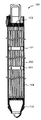
図1は、第1の実施形態に係る燃料集合体100の構成を示す縦断面図である。なお、図1は、BWRタイプの燃料集合体の場合であるが、PWRその他の炉型に対しても適用できる。以下は、主にBWRタイプの場合を例にとって説明する。
[First Embodiment]
FIG. 1 is a longitudinal sectional view showing a configuration of a
燃料集合体100は、複数の燃料棒200と、燃料スペーサ101、下部タイプレート102、上部タイプレート103、およびチャンネルボックス104を有する。
The
複数の燃料棒200は、それぞれ鉛直方向に延びて、互いに平行に正方格子状に配列されている。なお、正方格子状が一般的であるがこれに限定されず三角格子等でもよい。
The plurality of
これら複数の燃料棒200の下端は、BWRタイプの燃料集合体においては、下部構造部材を構成する下部タイプレート102によって結束され、拘束支持されている。また、これら複数の燃料棒200の上端は、BWRタイプの燃料集合体においては、上部構造部材を構成する上部タイプレート103によって結束され、拘束支持されている。なお、一部、上部タイプレート103には接続していない部分長燃料棒があってもよい。また、PWRタイプの燃料集合体においては、複数の燃料棒200の下端は下部構造部材としての下部ノズルに、複数の燃料棒200の上端は上部構造部材としての上部ノズルにそれぞれ支持されるが、BWRタイプの燃料集合体のように複数の燃料棒200が結束される形態とはなっていない。
The lower ends of the plurality of
さらに、これら複数の燃料棒200の上端と下端の間の鉛直方向に沿って、複数個所には、燃料スペーサ101が設けられている。燃料スペーサ101は、各燃料棒200の水平方向の移動を抑制する。
Furthermore,
また、チャンネルボックス104は、複数の燃料棒200が下部タイプレート102、燃料スペーサ101、および上部タイプレート103によって格子状に結束された状態で、下部タイプレート102から上部タイプレート103までの側面を覆うように設けられる。
The
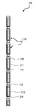
図2は燃料棒200の構成を概念的に示す縦断面図である。1本の燃料棒200は、複数のセグメント要素210を有する。セグメント要素210は、互いに上下方向に1列になるように接続されている。
FIG. 2 is a longitudinal sectional view conceptually showing the structure of the
それぞれのセグメント要素210は、被覆管212、上部端栓213、下部端栓214、および核燃料211を有する。被覆管212、上部端栓213、および下部端栓214のそれぞれの材質は、炭化ケイ素長繊維で強化された炭化ケイ素繊維強化複合材(SiC/SiC複合材)である。なお、SiC/SiC複合材に限定されず、高温条件で十分な安定性を有する材料であればSiC/SiC複合材以外の材料でもよい。
Each
被覆管212は、たとえば円筒状の上下が開放された管である。被覆管212の上端の開放部には、上部端栓213が取り付けられ、被覆管212と上部端栓213とは、たとえばろう付けなどで気密にシールされている。また、被覆管212の下端の開放部には、下部端栓214が取り付けられ、被覆管212と下部端栓214とは、同様に、たとえばろう付けなどで気密にシールされている。
The
被覆管212、上部端栓213、および下部端栓214によって形成された密閉空間内には、核燃料211が収納されている。核燃料211は、たとえばウラン235を濃縮した二酸化ウランペレットであるが、これに限定はされない。
核燃料211に占有されていない上部の空間には、プレナム216が形成されている。プレナム216は、核燃料211の燃焼が進むにつれて、当初封入されていたヘリウムガスなどの封入ガスに核分裂生成物であるクリプトンやキセノンなどの核分裂生成ガスが加わることにより、密閉空間内のガス圧が上昇するが、このガス圧を適正範囲内に抑えるための空間である。なお、プレナム216は、密閉空間内の上部に限定されない。たとえば、鉛直方向に下部、あるいは中間部に形成されていてもよい。
A
互いに上下に隣接するセグメント要素210間には、連結部300が設けられている。連結部300は、セグメント要素210間を、所定の曲げ剛性を以て接続するものである。ここで、曲げ剛性は、鉛直上下についての剛性ではなく、曲げ方向、すなわち、燃料棒200が延びる鉛直軸から逸脱する方向の変形に関する剛性をいう。
A connecting
後述の通り連結部300の曲げ剛性には上限値が存在し、少なくともセグメント要素210の曲げ剛性より低く設定される。セグメント要素210は、その構造体である被覆管212、上部端栓213および下部端栓214がSiC/SiC複合材製であり、剛性が極めて高い。このため、実質的に、燃料棒200の曲げ剛性は、鉛直方向に複数設けられた連結部300の部分の曲げ剛性により決まる。また、燃料集合体100の曲げ剛性は、BWRの場合は主にチャンネルボックス104およびこれに収納された複数の燃料棒200の合成された剛性である。また、PWRの場合は、主に複数の燃料棒200の合成された剛性である。
As will be described later, there is an upper limit value for the bending rigidity of the connecting
たとえば、連結部300の剛性が小さ過ぎる場合、燃料集合体100の全体の曲げ剛性が小さくなる。この結果、地震発生時には、燃料集合体100の燃料棒200の曲げ方向の変形量が大きくなる。この平均的な変位に、さらに個々の燃料棒200において個別の曲げ方向の変位が加わると、燃料棒200の曲げ方向の変形がさらに大きくなる。したがって、燃料集合体間に制御棒が挿入されるPWRタイプにおいても、燃料集合体内の燃料棒の曲げ変位が大きくなることは、制御棒クラスタの挿入性にとって好ましい方向ではない。
For example, when the rigidity of the connecting
このように、連結部300の剛性には、燃料集合体100の曲げ方向の変位、あるいはPWRの場合はさらに、燃料棒200の曲げ方向の変位が制御棒の挿入性を妨げないという条件からの、下限値が存在する。
As described above, the rigidity of the connecting
一方、連結部300の剛性が高すぎる場合、地震時の加速度による荷重を連結部300が吸収しきれずに、セグメント要素210に曲げ荷重がかかる。セグメント要素210の構造体でありSiC/SiC複合材である特に被覆管212は、過度の曲げ荷重が作用する場合、内部に微小なき裂が発生し核分裂生成ガスの漏洩が発生する可能性がある。したがって、被覆管212に過度の曲げ荷重が作用しないという目的から、連結部300の剛性には、上限値が存在する。
On the other hand, when the rigidity of the connecting
以上のように、連結部300の剛性は、制御棒の挿入性の観点からの下限値と、被覆管212の健全性確保の観点からの上限値との間の値であって、いずれの条件に対しても適正な裕度を確保できる範囲の値をとる必要がある。なお、この上限値、下限値は、連結部300の数を含めた燃料集合体100の構造に基づいて、評価の上決定することができる。
As described above, the rigidity of the connecting
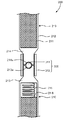
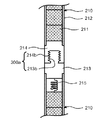
図3は、燃料棒200間の連結部300の構成を示す縦断面図である。セグメント要素210においては、被覆管212内に核燃料211が収納されている。図3の例では、核燃料211はたとえばペレットである。プレナム216には、プレナムスプリング215が設けられ、核燃料211を抑えて核燃料211の振動を抑制している。
FIG. 3 is a longitudinal sectional view showing the configuration of the connecting
連結部300は、ボール311および接続筒312を有する。また、ボール311の上方でボール311に隣接するセグメント要素210の下部端栓214に形成された凹部214a、およびボール311の下方でボール311に隣接するセグメント要素210の上部端栓213に形成された凹部213aは、連結部300を構成する。ボール311の形状は、球形または楕円回転体である。このように、連結部300は、上下に互いに隣接する2つのセグメント210が、接続筒312等を介して間接的に連結している、いわば間接的な連結部、すなわち間接連結部となっている。
The connecting
凹部214aおよび凹部213aは、上下に互いに対向して球形または楕円回転体に対応する空間を形成し、この空間内にボール311が収納されている。ボール311を挟んだ状態で、上部端栓213の上端と下部端栓214の下端の間には、ギャップが存在し、上部端栓213と下部端栓214とは相対的にボール311を挟んで回転可能な角度範囲を有する。
The
上部端栓213の上端部分と、下部端栓214の下端部分は、それぞれ外形が円柱状になっている。接続筒312は上下が開放された円筒状であり、ボール311を挟んだ状態の上部端栓213の上端部分と下部端栓214の下端部分の外周を包囲するよう設けられている。接続筒312は、上部端栓213の上端部分と下部端栓214の下端部分に、それぞれ取り付けられており、互いに上下に隣接するセグメント要素210同士を接続している。
Each of the upper end portion of the
たとえば、接続筒312と上部端栓213の上端部分との結合は、接続筒312および上部端栓213の上端部分を貫通する孔(図示せず)を形成し、この孔にピン(図示せず)を通すことにより固定できる。この場合、上部端栓213の上端部分に形成された孔とピンとの間に十分なギャップを形成させる。接続筒312と下部端栓214の下端部分との結合も同様に行う。
For example, the
接続筒312の内面と、上部端栓213の上端部分の外面、および下部端栓214の下端部分の外面の間には、所定のギャップが形成されている。互いに上下に隣接するセグメント要素210同士は、このギャップの範囲内で、曲げ方向に変形する。すなわち、燃料棒200の曲げ方向の変形は、このギャップでコントロールされる。
A predetermined gap is formed between the inner surface of the
なお、接続筒312の内面と上部端栓213の上端部分の外面との間、および接続筒312の内面と下部端栓214の下端部分の外面の間に、周方向に3か所あるいはそれ以上の個数のバネ(図示せず)を互いに等間隔で設けてもよい。バネを設ける個所、このバネの剛性等を調整することにより、燃料棒200、ひいては燃料集合体100の曲げ剛性を調整することができる。あるいは、接続筒312自体をバネ材としてもよい。
It should be noted that there are three or more in the circumferential direction between the inner surface of the
図4は、燃料集合体100のセグメント要素210間の連結部300の位置における燃料棒200間の相互関係を示す縦断面図である。複数の燃料棒200はそれぞれ、前述のように、核燃料211を有するセグメント要素210が互いに上下に連結部300を介して接続している。連結部300には核燃料211は収納されていないので、核燃料の鉛直方向の分布は、それぞれの連結部300において中断している。
FIG. 4 is a longitudinal sectional view showing the mutual relationship between the
図4に示す燃料棒200の配列では、各燃料棒200における連結部300の高さ位置が異なっている。このため、燃料集合体100の全体として、いずれの高さ位置においても、いずれかの燃料棒200には核燃料が必ず存在する。
In the arrangement of the
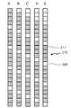
図5は、燃料棒の種類を示す縦断面図である。図で、A、B、C、D、およびEは、燃料棒200の種類を表し、その構成がそれぞれの下に表示されている。図5において、斜線部は核燃料211を内包するセグメント要素210の部分であり、白抜きの部分は連結部300を含めた核燃料211を内包しない部分である。縦方向に、白抜き部が1つに対して斜線部が4つとなっているのは、概略、核燃料211を内包する部分の長さが核燃料を内包しない部分の長さの約4倍と想定したためである。それぞれ、縦方向の並び方のみが異なっており、AないしEまで、1つずつ下方にずれている。A、B、C、D、およびEを、高さ方向に比較すると、いずれの高さにおいても、必ず、核燃料が存在する。
FIG. 5 is a longitudinal sectional view showing the types of fuel rods. In the figure, A, B, C, D, and E represent the types of
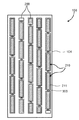
図6は、燃料棒200の配列の例を示す水平断面図である。図6の10×10の配列においては、いずれの燃料棒の周囲にも、同じ種類の燃料棒が存在しない配列となっている。この配列においては、図中で横方向に見たいずれの列、あるいは図中で縦方向に見たいずれの列においても、かならず5種類の燃料が存在している。すなわち、このような配列においては、図中の縦方向、横方向のいずれの断面においても、いずれの高さでも核燃料を有する部分が存在する配列となっている。
FIG. 6 is a horizontal sectional view showing an example of the arrangement of the
セグメント要素210を用いると、連結部300やプレナム216など核燃料211が存在しない領域に隣接する燃料棒200においては、ウラン等の核燃料物質による中性子吸収が減る。このため、この隣接する燃料棒200のこの部分の局所出力が上昇する出力スパイクが生じることがある。燃料の健全性を保つための運転制限値などは最大線出力密度で定められるため、局所的な出力スパイクが存在するとその部分の平均出力を低下させる必要が生じ、燃料の燃焼効率が低下する。
When the
出力スパイク防止のためには、プレナム部に中性子吸収体を配置する方法もあるが、セグメント燃料が炉心全体を構成している場合にこの方法を用いることは、炉心内に大量の中性子吸収体を持ち込むこととなり中性子経済性を著しく低下させる。図6に示すような構成によって、核燃料物質を含まない領域を分散して配置し、中性子吸収の不均一性を減らすことにより、出力スパイクを抑制することができる。 In order to prevent output spikes, there is a method of arranging a neutron absorber in the plenum part, but using this method when segment fuel constitutes the entire core, a large amount of neutron absorber is placed in the core. This will significantly reduce the neutron economy. With the configuration as shown in FIG. 6, output spikes can be suppressed by dispersing and arranging regions that do not contain nuclear fuel material and reducing non-uniform neutron absorption.
ここで、燃料棒200の上端部および下端部以外のセグメント要素210を鉛直方向に見て、核燃料211が存在する部分の長さと、それ以外の部分、すなわち上部端栓213、下部端栓214、プレナム216、および連結部300を合わせた部分との長さの概略の比を図5に示すようにn:1とする。たとえば、図5に示す場合は、白抜きのブロックが1つに対して斜線部のブロックの数が4であるので、n=4である。この場合は、(n+1)=5であるので、セグメント要素210の鉛直方向のピッチの1/5ずつ鉛直方向に互いにずらした5種類の燃料棒があれば図6に示すように、いずれの高さにおいても核燃料211が存在し、スパイクの発生を抑制できる。
Here, when the
なお、10×10配列の場合は、10が5の倍数であることから、図5に示すように、5種類の燃料棒200をいずれの方向にも均等に配分することができる。このように、燃料集合体100内の非均質性をさらに抑えることによって、スパイクの発生をさらに抑制することができる。
In the case of a 10 × 10 array, since 10 is a multiple of 5, five types of
前記のnの値によって、燃料棒200の種類を設定することとすると、nが大きくなると、燃料棒200の上端部、下端部に設けるセグメント要素210の種類が増えることになる。このため、nの大きさは適当な大きさにとどめたい。このためには、密閉空間内のプレナム216の長さを調整する必要が生ずる。
If the type of the
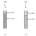
図7は燃料棒200内の中空燃料との比較を示す縦断面図であり、(a)は中空燃料、(b)は中実燃料の場合を示す。(a)の中実燃料の場合のセグメント要素210a内のプレナム216aは、核燃料211aが中空であるため、プレナムとしての体積は、密閉空間上部の核燃料211aのない範囲の体積と、核燃料211aに囲まれた中央部の体積の和となる。
FIG. 7 is a longitudinal sectional view showing a comparison with the hollow fuel in the
したがって、中実の核燃料211bでプレナム216bを有するセグメント要素210bに比べて、密閉空間内の核燃料のない部分の長さを短くすることができる。このように、中空燃料を導入することによって、前記のnの値を調整することができる。
Therefore, compared with the
図8は、燃料棒の配列を示す水平配列図および縦断面図であり、(a)で示すケース1はセグメント要素が1種類、(b)で示すケース2は3種類、(c)で示すケース3は5種類の場合である。図8(b)のケース2の3種類の場合、いずれの立断面においても、全ての高さに3種類の燃料棒が存在する配列である。また、図8(c)のケース3の5種類の場合、いずれの立断面においても、全ての高さに5種類の燃料棒が存在する配列である。説明の便宜上、5×5の配列の場合を示している。
FIG. 8 is a horizontal arrangement diagram and a longitudinal sectional view showing the arrangement of fuel rods.
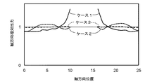
図9は、図8の各ケースにおける軸方向の相対出力を比較するグラフである。横軸は、図8において、それぞれ下側から数えたブロックの順番である。縦軸は、相対出力である。ケース1の燃料棒200は、下から数えて11ブロック目から15ブロック目に核燃料を有さず相対値が算出できないため、この領域は曲線がない。
FIG. 9 is a graph comparing the relative output in the axial direction in each case of FIG. The horizontal axis is the order of the blocks counted from the lower side in FIG. The vertical axis is the relative output. The
図9に示すように、ケース1では、中間の核燃料が有る領域とない領域の境界で相対出力が大きくなっている。すなわち局部ピークが大きい。ケース2では、大幅に緩和されている。また、燃料棒200の種類を5種類に増やしたケース3では、相対出力がさらに平坦化されている。このように、燃料棒200の種類を増やして、互いにずれた位置におく本実施形態の方式により、相対出力の平坦化の効果が得られている。
As shown in FIG. 9, in
以上のように、本実施形態によれば、長尺の燃料棒ではなく、短尺のセグメント要素を用いることにより、長い管を製造する必要性がなくなる。短尺であることにより製造性のよい管を用いて燃料集合体100を構成することが出来る。また、円柱状の燃料棒200を格子状に配列して燃料集合体100を構成するという点で、既存燃料との類似性を有しており、既存炉への装荷が可能となる。
As described above, according to the present embodiment, it is not necessary to manufacture a long tube by using a short segment element instead of a long fuel rod. Due to the short length, the
また、セグメント要素210間の連結部300の構造を適切に設計することにより、燃料棒200が破損せずに折れ曲がることが出来るため、セグメント要素210自体の曲がりは最小限にとどめ燃料棒全体として撓ることが出来るようになる。これによって、地震などにより振動が加わり、燃料集合体100に曲げ荷重がかかった場合においても、連結部300が曲がることによりSiC/SiC複合材にかかる荷重を軽減できる。この結果、被覆管212に生じる亀裂発生の可能性を最小限に抑え、FPガスの漏洩などの可能性を最小化することができる。
In addition, by appropriately designing the structure of the connecting
さらに、仮に亀裂が生じたとしても、セグメント要素210内の核分裂生成物の量は小さいため、その影響も最小限にとどまる。
Furthermore, even if a crack occurs, the amount of fission products in the
以上のように、本実施形態によれば、SiC/SiC複合材を用いた場合でも十分な製造性を有している。また、現存する原子炉に装荷できる程度に従来の金属製被覆管の燃料集合体と構造上の類似性をもち、現存する原子炉への適合性を有している。 As described above, according to the present embodiment, sufficient manufacturability is obtained even when the SiC / SiC composite material is used. In addition, it has structural similarity to the conventional metal cladding tube fuel assembly to the extent that it can be loaded into existing reactors, and is compatible with existing reactors.
[第2の実施形態]
図10は、第2の実施形態に係る燃料棒200間の連結部300aの構成を示す縦断面図である。互いに上下に隣接する燃料棒200のうち、上側の燃料棒200の下部端栓214にはめねじ部214bが形成されている。また、下側の燃料棒200の上部端栓213にはおねじ部213bが形成されている。
[Second Embodiment]
FIG. 10 is a longitudinal sectional view showing the configuration of the connecting
おねじ部213bとめねじ部214bは互いに螺合している。おねじ部213bとめねじ部214bは、連結部300aを構成している。なお、上側の燃料棒200の下部端栓214に、おねじ部が形成され、下側の燃料棒200の上部端栓213に、めねじ部が形成されていてもよい。このように、連結部300aは、上下に互いに隣接する2つのセグメント210が、それぞれの端部で螺合して直接的に連結している、いわば直接的な連結部、すなわち直接連結部となっている。
The
このように構成された本第2の実施形態においては、それぞれの連結部300aが1つのネジ部を有することから、燃料棒200の剛性がこの分低下する。これにより、燃料棒200の曲げ剛性の調整機能が備わる。
In the second embodiment configured as described above, each connecting
図11は、燃料棒間の連結部の変形例の構成を示す縦断面図である。この変形例の連結部300bにおいては、上側の燃料棒200の下部端栓214と下側の燃料棒200の上部端栓213の間には、中間ねじ部313が設けられている。
FIG. 11 is a longitudinal sectional view showing a configuration of a modified example of the connecting portion between the fuel rods. In the connecting
上側の燃料棒200の下部端栓214にはおねじ部214cが形成されている。下側の燃料棒200の上部端栓213にはおねじ部213bが形成されている。中間ねじ部313は、外形が上下に延びた円柱状で、上端および下端に、それぞれめねじ部313bが形成されている。中間ねじ部313の上端のめねじ部313bと上側の燃料棒200の下部端栓214に形成されたおねじ部214cとが互いに螺合している。また、中間ねじ部313の下端のめねじ部313bと下側の燃料棒200の上部端栓213に形成されたおねじ部213bとが互いに螺合している。
The
なお、上側の燃料棒200の下部端栓214および下側の燃料棒200の上部端栓213にめねじ部が形成され、中間ねじ部313の上端および下端にそれぞれおねじ部が形成されていてもよい。このように、連結部300bは、上下に互いに隣接する2つのセグメント210が、中間ねじ部313を介して間接的に連結している、すなわち間接連結部となっている。
A female thread portion is formed at the
このように構成された本変形例においては、連結部300bが2つのネジ部を有することから、燃料棒200の剛性がさらに低下する。また、第2の実施形態による結合方式と、変形例による結合方式を組み合わせれば、両者の中間の剛性を確保することができる。
In this modified example configured as described above, since the connecting
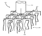
[第3の実施形態]
図12は、第3の実施形態に係る燃料集合体の燃料棒間の連結部300であるジョイントスペーサ410の構成を示す斜視図である。ジョイントスペーサ410は、正方格子状に組み合わされた格子板411と、格子板411に取り付けられた板バネ412を有する。板バネ412は、それぞれの格子の内側の4面に取り付けられている。なお、互いに隣接する2面のみに取り付けられることでもよい。
[Third Embodiment]
FIG. 12 is a perspective view showing a configuration of a
それぞれの格子には、上方からセグメント要素210の下部端栓214が挿入される。板バネ412は、下部端栓214が下向きの挿入される際に、板バネ412の下端が下向きにスライドして、下部端栓214が挿入されるスペースを形成する。
A
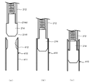
図13は、第3の実施形態に係る燃料集合体の燃料棒間の連結部であるジョイントスペーサ410での結合の状態を示す縦断面図であり、(a)は挿入前、(b)は挿入中、(c)は挿入後の結合状態を示す。下部端栓214と被覆管212とは段付き部214dを形成する。すなわち、下部端栓214の被覆管212に隣接する部分の外径は、被覆管212の外径より大きくなっている。また、下部端栓214の先端は、挿入しやすいようにテーパー部214fが形成されている。
FIGS. 13A and 13B are longitudinal sectional views showing a coupling state at a
図13の(b)の挿入中は、板バネ412は格子板411に押し付けられている。図13の(c)の段階では、板バネ412は復帰し、段付き部214dは、板バネ412によって上方への移動を拘束される。
During the insertion of FIG. 13B, the
以上は、ジョイントスペーサ410の上部の構成である。ジョイントスペーサ410の下部においても、同様の構成である。したがって、下方に隣接するセグメント要素210の上部端栓213とも、同様に結合する。
The above is the configuration of the upper portion of the
なお、全てのセグメント要素210が同じ高さでジョイントスペーサ410に結合すると燃料集合体100の出力分布が平坦化されない。このため、燃料棒200をグループ化して、それぞれのグループにジョイントスペーサ410を対応させる。対応しないグループの燃料棒200のセグメント要素210の場合は、ジョイントスペーサ410の板バネ412には、被覆管212の部分が対向する状態となる。
If all the
以上のように、本実施形態によれば、連結部300でもあるジョイントスペーサ410は、燃料棒200の上下に互いに隣接するセグメント要素210間に設けられ、このセグメント要素210を上下に結合するとともに、水平方向にも燃料棒200を拘束する。
As described above, according to the present embodiment, the
ジョイントスペーサ410は、板バネ412を介して燃料棒200を拘束することから、燃料棒200の曲げ剛性を適切に調整することができる。
Since the
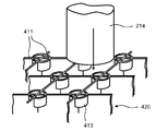
[第4の実施形態]
図14は、第4の実施形態に係る燃料集合体の燃料棒間の連結部であるジョイントスペーサの構成を示す斜視図である。本実施形態は、第3の実施形態の変形である。本第4の実施形態は、第3の実施形態の板バネ412に代えて、円筒バネ413が、各格子内の全てのコーナー部に設けられている。なお、各格子内の互いに隣接する2つのコーナー部のみに設けられることでもよい。ここで、円筒バネ413は、それぞれのコーナー部に円筒の一部の周角度範囲の部分である。
[Fourth Embodiment]
FIG. 14 is a perspective view illustrating a configuration of a joint spacer that is a connecting portion between fuel rods of the fuel assembly according to the fourth embodiment. This embodiment is a modification of the third embodiment. In the fourth embodiment, instead of the
下部端栓214は、挿入の過程で円筒バネ413の周方向の中央と接触する。円筒バネ413は、中央部分からの変形についての剛性は高い。したがって、本第4の実施形態における連結部としてのジョイントスペーサ420を用いることにより、第3の実施形態に比べて高い剛性の連結部を実現することができ、燃料集合体100の剛性の調整幅をさらに広げることができる。
The
[その他の実施形態]
以上、本発明のいくつかの実施形態を説明したが、これらの実施形態は、例として提示したものであり、発明の範囲を限定することは意図していない。たとえば、第1の実施形態では、図1で、BWRの燃料集合体の場合を示したが、BWRに限定されない。チャンネルボックスが設けられていないPWRの場合にも適用でき、連結部の所定の剛性の必要性は、燃料集合体中に中性子吸収体が挿入されるPWRにおいて特に要求される。
[Other Embodiments]
As mentioned above, although some embodiment of this invention was described, these embodiment is shown as an example and is not intending limiting the range of invention. For example, in the first embodiment, the case of the fuel assembly of BWR is shown in FIG. 1, but it is not limited to BWR. The present invention can also be applied to the case of a PWR not provided with a channel box, and the necessity for a predetermined rigidity of the connecting portion is particularly required in a PWR in which a neutron absorber is inserted into a fuel assembly.
また、各実施形態の特徴を組み合わせてもよい。さらに、これらの実施形態は、その他の様々な形態で実施されることが可能であり、発明の要旨を逸脱しない範囲で、種々の省略、置き換え、変更を行うことができる。これら実施形態やその変形は、発明の範囲や要旨に含まれると同様に、特許請求の範囲に記載された発明とその均等の範囲に含まれるものである。 Moreover, you may combine the characteristic of each embodiment. Furthermore, these embodiments can be implemented in various other forms, and various omissions, replacements, and changes can be made without departing from the scope of the invention. These embodiments and their modifications are included in the scope and gist of the invention, and are also included in the invention described in the claims and the equivalents thereof.
100…燃料集合体、101…燃料スペーサ、102…下部タイプレート(下部構造部材)、103…上部タイプレート(上部構造部材)、104…チャンネルボックス、200…燃料棒、210、210a、210b…セグメント要素、211、211a、211b…核燃料、212…被覆管、213…上部端栓、213a…凹部、213b…おねじ部、214…下部端栓、214a…凹部、214b…めねじ部、214c…おねじ部、214d…段付き部、214f…テーパー部、215…プレナムスプリング、216、216a、216b…プレナム、300…連結部(第1の間接連結部)、300a…連結部(直接連結部)、300b…連結部(第2の間接連結部)、311…ボール、312…接続筒、313…中間ねじ部、313b…めねじ部、410、420…ジョイントスペーサ、411…格子板、412…板バネ、413…円筒バネ
DESCRIPTION OF
Claims (9)
前記複数の燃料棒の上端を支持する上部構造部材と、
前記複数の燃料棒の下端を支持する下部構造部材と、
を備え、
前記燃料棒はそれぞれ、
鉛直方向に延びる核燃料と、前記核燃料を収納して鉛直方向に延びて上端および下端が開放された炭化ケイ素繊維強化複合材製の被覆管と、前記被覆管の上端の開放部を塞ぐ炭化ケイ素繊維強化複合材製の上部端栓と、前記被覆管の下端の開放部を塞ぐ炭化ケイ素繊維強化複合材製の下部端栓と、を有し互いに鉛直方向に直列に配列された複数のセグメント要素と、
互いに上下に隣接する前記セグメント要素間を所定の範囲の曲げ剛性をもって接続する連結部と、
を具備することを特徴とする燃料集合体。 A plurality of fuel rods extending in parallel to each other in the vertical direction and arranged in a grid in the horizontal direction;
An upper structural member that supports upper ends of the plurality of fuel rods;
A lower structural member supporting lower ends of the plurality of fuel rods;
With
Each of the fuel rods
A nuclear fuel extending in the vertical direction, a cladding tube made of a silicon carbide fiber reinforced composite material containing the nuclear fuel and extending in the vertical direction and having an upper end and a lower end opened, and a silicon carbide fiber blocking the open portion at the upper end of the cladding tube A plurality of segment elements having an upper end plug made of a reinforced composite material and a lower end plug made of a silicon carbide fiber reinforced composite material that closes the opening at the lower end of the cladding tube and arranged in series in the vertical direction. ,
A connecting portion that connects the segment elements adjacent to each other vertically with a predetermined range of bending rigidity;
A fuel assembly comprising:
前記連結部は、
前記下部端栓および前記上部端栓のそれぞれに形成され互いに対向する前記凹部間に収納されたボールと、
前記下部端栓および前記上部端栓の両者を拘束するように前記下部端栓の先端部および前記上部端栓の先端部の径方向の周囲を覆うように設けられた接続筒と、
を有する第1の間接連結部を含むことを特徴とする請求項1に記載の燃料集合体。 A recess is formed on the upper surface of the upper end plug and the lower surface of the lower end plug,
The connecting portion is
A ball housed between the recesses formed in each of the lower end plug and the upper end plug and facing each other;
A connecting tube provided so as to cover the periphery of the distal end portion of the lower end plug and the distal end portion of the upper end plug so as to constrain both the lower end plug and the upper end plug;
The fuel assembly according to claim 1, further comprising a first indirect coupling portion having the following.
前記連結部は、前記おねじとめねじで結合される直接連結部を含むことを特徴とする請求項1または請求項2に記載の燃料集合体。 On the upper part of the upper end plug and the lower part of the lower end plug adjacent to each other, a male screw or a female screw that can be engaged with each other is formed,
The fuel assembly according to claim 1, wherein the connecting portion includes a direct connecting portion coupled by the male screw and the female screw.
前記連結部は、前記おねじまたはめねじと結合可能なめねじまたはおねじが上端および下端に形成された中間ねじ部を有する第2の間接連結部を含むことを特徴とする請求項1ないし請求項3のいずれか一項に記載の燃料集合体。 Each of the upper end plug and the lower end plug adjacent to each other is formed with a male screw or a female screw,
The said connection part contains the 2nd indirect connection part which has the intermediate | middle thread part by which the internal thread or external thread which can be combined with the said external thread or internal thread was formed in the upper end and the lower end. Item 4. The fuel assembly according to any one of Items 3.
前記燃料棒は、nを1以上の整数として、前記セグメント要素の鉛直方向に核燃料が存在する部分とそれ以外の部分の長さの比をn:1に近似した場合に、前記セグメント要素の鉛直方向の位置を前記セグメント要素の長さの1/(n+1)ずつずらして配置した(n+1)種類を有することを特徴とする請求項1ないし請求項7のいずれか一項に記載の燃料集合体。 All of the segment elements that are not located at the upper and lower ends of the fuel rods have the same length,
The fuel rod has a vertical length of the segment element when n is an integer equal to or greater than 1 and the ratio of the length of the portion where the nuclear fuel is present in the vertical direction of the segment element to the other portion is approximated to n: 1. The fuel assembly according to any one of claims 1 to 7, wherein the fuel assembly has (n + 1) types in which the position in the direction is shifted by 1 / (n + 1) of the length of the segment element. .
互いに上下に隣接する前記セグメント要素間を所定の範囲の曲げ剛性をもって接続する連結部と、
を備えることを特徴とする燃料棒。 A nuclear fuel extending in the vertical direction, a cladding tube made of a silicon carbide fiber reinforced composite material containing the nuclear fuel and extending in the vertical direction and having an upper end and a lower end opened, and a silicon carbide fiber blocking the open portion at the upper end of the cladding tube A plurality of segment elements having an upper end plug made of a reinforced composite and a lower end plug made of a silicon carbide fiber reinforced composite that closes the opening of the lower end and arranged in series in the vertical direction;
A connecting portion that connects the segment elements adjacent to each other vertically with a predetermined range of bending rigidity;
A fuel rod comprising:
Priority Applications (1)
| Application Number | Priority Date | Filing Date | Title |
|---|---|---|---|
| JP2015079602A JP6666072B2 (en) | 2015-04-08 | 2015-04-08 | Fuel rods and fuel assemblies |
Applications Claiming Priority (1)
| Application Number | Priority Date | Filing Date | Title |
|---|---|---|---|
| JP2015079602A JP6666072B2 (en) | 2015-04-08 | 2015-04-08 | Fuel rods and fuel assemblies |
Publications (2)
| Publication Number | Publication Date |
|---|---|
| JP2016200465A true JP2016200465A (en) | 2016-12-01 |
| JP6666072B2 JP6666072B2 (en) | 2020-03-13 |
Family
ID=57422945
Family Applications (1)
| Application Number | Title | Priority Date | Filing Date |
|---|---|---|---|
| JP2015079602A Active JP6666072B2 (en) | 2015-04-08 | 2015-04-08 | Fuel rods and fuel assemblies |
Country Status (1)
| Country | Link |
|---|---|
| JP (1) | JP6666072B2 (en) |
Cited By (5)
| Publication number | Priority date | Publication date | Assignee | Title |
|---|---|---|---|---|
| CN108231216A (en) * | 2017-12-14 | 2018-06-29 | 广东核电合营有限公司 | A kind of composite type fuel component, nuclear reactor and assemble method |
| JP2019052075A (en) * | 2017-09-19 | 2019-04-04 | 三菱重工業株式会社 | Shear resistance high thermostability inorganic fiber bonded ceramic-made rod shape component and production method thereof |
| JP2022081558A (en) * | 2017-09-25 | 2022-05-31 | 株式会社東芝 | Method of closing openings in fuel cladding and fuel cladding |
| JP2022538684A (en) * | 2019-07-02 | 2022-09-05 | ウェスティングハウス エレクトリック カンパニー エルエルシー | elongated SiC fuel element |
| CN116168853A (en) * | 2022-12-08 | 2023-05-26 | 中国原子能科学研究院 | A hexagonal fuel assembly for heating stack |
Families Citing this family (1)
| Publication number | Priority date | Publication date | Assignee | Title |
|---|---|---|---|---|
| JP7427626B2 (en) * | 2021-03-18 | 2024-02-05 | 株式会社東芝 | Channel box and fuel assembly |
Citations (10)
| Publication number | Priority date | Publication date | Assignee | Title |
|---|---|---|---|---|
| JPS4632076Y1 (en) * | 1965-09-29 | 1971-11-05 | ||
| JPS61139492U (en) * | 1985-02-19 | 1986-08-29 | ||
| JPS61206900U (en) * | 1985-06-14 | 1986-12-27 | ||
| JPS63235890A (en) * | 1987-03-25 | 1988-09-30 | 株式会社日立製作所 | fuel assembly |
| JPH01212394A (en) * | 1988-02-19 | 1989-08-25 | Hitachi Ltd | Fuel assembly |
| JPH0319993U (en) * | 1989-07-06 | 1991-02-27 | ||
| US5182077A (en) * | 1991-04-15 | 1993-01-26 | Gamma Engineering Corporation | Water cooled nuclear reactor and fuel elements therefor |
| JPH0967165A (en) * | 1995-08-30 | 1997-03-11 | Hitachi Ltd | Silicon carbide ceramics and method for producing the same |
| JP2008501977A (en) * | 2004-06-07 | 2008-01-24 | ウエスチングハウス・エレクトリック・カンパニー・エルエルシー | Multilayer ceramic tubes used for fuel containment barriers in nuclear power plants |
| JP2012058244A (en) * | 2010-09-10 | 2012-03-22 | Ge-Hitachi Nuclear Energy Americas Llc | Fuel rod assembly for nuclear reactors |
-
2015
- 2015-04-08 JP JP2015079602A patent/JP6666072B2/en active Active
Patent Citations (10)
| Publication number | Priority date | Publication date | Assignee | Title |
|---|---|---|---|---|
| JPS4632076Y1 (en) * | 1965-09-29 | 1971-11-05 | ||
| JPS61139492U (en) * | 1985-02-19 | 1986-08-29 | ||
| JPS61206900U (en) * | 1985-06-14 | 1986-12-27 | ||
| JPS63235890A (en) * | 1987-03-25 | 1988-09-30 | 株式会社日立製作所 | fuel assembly |
| JPH01212394A (en) * | 1988-02-19 | 1989-08-25 | Hitachi Ltd | Fuel assembly |
| JPH0319993U (en) * | 1989-07-06 | 1991-02-27 | ||
| US5182077A (en) * | 1991-04-15 | 1993-01-26 | Gamma Engineering Corporation | Water cooled nuclear reactor and fuel elements therefor |
| JPH0967165A (en) * | 1995-08-30 | 1997-03-11 | Hitachi Ltd | Silicon carbide ceramics and method for producing the same |
| JP2008501977A (en) * | 2004-06-07 | 2008-01-24 | ウエスチングハウス・エレクトリック・カンパニー・エルエルシー | Multilayer ceramic tubes used for fuel containment barriers in nuclear power plants |
| JP2012058244A (en) * | 2010-09-10 | 2012-03-22 | Ge-Hitachi Nuclear Energy Americas Llc | Fuel rod assembly for nuclear reactors |
Cited By (8)
| Publication number | Priority date | Publication date | Assignee | Title |
|---|---|---|---|---|
| JP2019052075A (en) * | 2017-09-19 | 2019-04-04 | 三菱重工業株式会社 | Shear resistance high thermostability inorganic fiber bonded ceramic-made rod shape component and production method thereof |
| JP2022081558A (en) * | 2017-09-25 | 2022-05-31 | 株式会社東芝 | Method of closing openings in fuel cladding and fuel cladding |
| JP7238183B2 (en) | 2017-09-25 | 2023-03-13 | 株式会社東芝 | Fuel cladding and method for closing openings in fuel cladding |
| US12448173B2 (en) | 2017-09-25 | 2025-10-21 | Kabushiki Kaisha Toshiba | Container and method for closing an opening of container |
| CN108231216A (en) * | 2017-12-14 | 2018-06-29 | 广东核电合营有限公司 | A kind of composite type fuel component, nuclear reactor and assemble method |
| JP2022538684A (en) * | 2019-07-02 | 2022-09-05 | ウェスティングハウス エレクトリック カンパニー エルエルシー | elongated SiC fuel element |
| JP7583015B2 (en) | 2019-07-02 | 2024-11-13 | ウェスティングハウス エレクトリック カンパニー エルエルシー | Elongated SiC fuel element |
| CN116168853A (en) * | 2022-12-08 | 2023-05-26 | 中国原子能科学研究院 | A hexagonal fuel assembly for heating stack |
Also Published As
| Publication number | Publication date |
|---|---|
| JP6666072B2 (en) | 2020-03-13 |
Similar Documents
| Publication | Publication Date | Title |
|---|---|---|
| JP6666072B2 (en) | Fuel rods and fuel assemblies | |
| US11942229B2 (en) | Molten metal fuel buffer in fission reactor and method of manufacture | |
| US10541057B2 (en) | Light water reactor fuel rod having ceramic cladding tube and ceramic end plug | |
| US20100135452A1 (en) | Liquid-metal-cooled fast reactor core comprising nuclear fuel assembly with nuclear fuel rods with varying fuel cladding thickness in each of the reactor core regions | |
| US20200027583A1 (en) | Annular metal nuclear fuel and methods of manufacturing the same | |
| JP2008501977A (en) | Multilayer ceramic tubes used for fuel containment barriers in nuclear power plants | |
| JP5469074B2 (en) | Support device for nuclear fuel plate for fissionable bundle of GFR nuclear reactor with high-temperature heat conduction gas, fissionable bundle including the support device, and nuclear fuel core assembly including the fissionable bundle | |
| US10475542B2 (en) | Nuclear fuel rod | |
| TWI810737B (en) | High energy nuclear fuel, fuel assembly, and refueling method | |
| CN106875984B (en) | A kind of new accident fault tolerant fuel component | |
| US9378852B2 (en) | Spacer grids for nuclear reactor | |
| RU2242810C2 (en) | Fuel assembly for water-moderated water-cooled reactor | |
| TWI820584B (en) | channel box and fuel assembly | |
| EP4141889A1 (en) | Fuel rod of a water-cooled water-moderated nuclear reactor | |
| Grasso et al. | The core of the LFR-AS-200: robustness for safety | |
| JP6691000B2 (en) | Fuel rods and fuel assemblies | |
| CN108140435A (en) | The component of the sodium-cooled fast reactor type nuclear reactor of isolation plate that its shell is improved equipped with rigidity | |
| RU2236712C2 (en) | Control fuel assembly of pressurized water reactors | |
| RU2166214C1 (en) | Composite fuel assembly for power control system of nuclear reactor core | |
| Barnes | CDFR design and performance implications of extended burn-up | |
| JP2022185700A (en) | Fuel assembly, and reactor core of fast reactor | |
| JP2711342B2 (en) | Fuel assembly for boiling water reactor | |
| Markov et al. | Stability of mechanical properties and geometry of new generation VVER-1000 FAs operated up to 6 years | |
| RU2248629C2 (en) | Water-moderated water cooled-reactor core | |
| JP2018072053A (en) | Control rod for light water reactor |
Legal Events
| Date | Code | Title | Description |
|---|---|---|---|
| A711 | Notification of change in applicant |
Free format text: JAPANESE INTERMEDIATE CODE: A711 Effective date: 20171201 Free format text: JAPANESE INTERMEDIATE CODE: A712 Effective date: 20171201 |
|
| A621 | Written request for application examination |
Free format text: JAPANESE INTERMEDIATE CODE: A621 Effective date: 20180219 |
|
| A977 | Report on retrieval |
Free format text: JAPANESE INTERMEDIATE CODE: A971007 Effective date: 20181109 |
|
| A131 | Notification of reasons for refusal |
Free format text: JAPANESE INTERMEDIATE CODE: A131 Effective date: 20181204 |
|
| A521 | Request for written amendment filed |
Free format text: JAPANESE INTERMEDIATE CODE: A523 Effective date: 20190201 |
|
| A131 | Notification of reasons for refusal |
Free format text: JAPANESE INTERMEDIATE CODE: A131 Effective date: 20190702 |
|
| A521 | Request for written amendment filed |
Free format text: JAPANESE INTERMEDIATE CODE: A523 Effective date: 20190828 |
|
| TRDD | Decision of grant or rejection written | ||
| A01 | Written decision to grant a patent or to grant a registration (utility model) |
Free format text: JAPANESE INTERMEDIATE CODE: A01 Effective date: 20200121 |
|
| A61 | First payment of annual fees (during grant procedure) |
Free format text: JAPANESE INTERMEDIATE CODE: A61 Effective date: 20200220 |
|
| R150 | Certificate of patent or registration of utility model |
Ref document number: 6666072 Country of ref document: JP Free format text: JAPANESE INTERMEDIATE CODE: R150 |