JP2016210312A - Power unit for hybrid type saddle-riding type vehicle and hybrid type saddle-riding type vehicle - Google Patents
Power unit for hybrid type saddle-riding type vehicle and hybrid type saddle-riding type vehicle Download PDFInfo
- Publication number
- JP2016210312A JP2016210312A JP2015096323A JP2015096323A JP2016210312A JP 2016210312 A JP2016210312 A JP 2016210312A JP 2015096323 A JP2015096323 A JP 2015096323A JP 2015096323 A JP2015096323 A JP 2015096323A JP 2016210312 A JP2016210312 A JP 2016210312A
- Authority
- JP
- Japan
- Prior art keywords
- electric motor
- engine
- type vehicle
- reduction mechanism
- gear
- Prior art date
- Legal status (The legal status is an assumption and is not a legal conclusion. Google has not performed a legal analysis and makes no representation as to the accuracy of the status listed.)
- Pending
Links
Images



Landscapes
- Hybrid Electric Vehicles (AREA)
Abstract
【課題】エンジンに加えて電動モータを搭載しても、ハイブリッド式鞍乗型車両の大型化を抑制できるハイブリッド式鞍乗型車両用パワーユニットを提供すること。【解決手段】ハイブリッド式鞍乗型車両用パワーユニット12は、エンジントルクを発生するエンジン16と、駆動用バッテリーの電力により電動モータトルクを発生する電動モータ40と、駆動輪が固定される出力軸34と、エンジンから出力軸へエンジントルクを伝達するエンジントルク伝達経路中に設けられ、エンジントルクを増加して出力軸へ伝達するエンジン用減速機構90と、電動モータから出力軸へ電動モータトルクを伝達する電動モータトルク伝達経路中に設けられ、電動モータトルクを増加し、増加された電動モータトルクがエンジン用減速機構の少なくとも一部によって更に増加されて、出力軸へ伝達されるように配置された電動モータ用減速機構91と、を備える。【選択図】図3A power unit for a hybrid straddle-type vehicle capable of suppressing an increase in size of the hybrid straddle-type vehicle even when an electric motor is mounted in addition to the engine. A hybrid straddle-type vehicle power unit 12 includes an engine 16 that generates engine torque, an electric motor 40 that generates electric motor torque by electric power of a driving battery, and an output shaft 34 to which driving wheels are fixed. And an engine speed reduction mechanism 90 that increases the engine torque and transmits the engine torque to the output shaft, and transmits the electric motor torque from the electric motor to the output shaft. Is arranged in the electric motor torque transmission path to increase the electric motor torque, and the increased electric motor torque is further increased by at least a part of the engine deceleration mechanism and transmitted to the output shaft. An electric motor reduction mechanism 91. [Selection] Figure 3
Description
本発明は、ハイブリッド式鞍乗型車両用パワーユニット、および、ハイブリッド式鞍乗型車両に関する。 The present invention relates to a power unit for a hybrid straddle-type vehicle and a hybrid straddle-type vehicle.
特許文献1には、ハイブリッド式鞍乗型車両が開示されている。ハイブリッド式鞍乗型車両は、エンジンと、駆動用バッテリーと、電動モータとを備えている。ハイブリッド式鞍乗型車両は、エンジンで発生したエンジントルクを駆動輪に伝達することができ、また、駆動用バッテリーにより電動モータを駆動し、電動モータで発生した電動モータトルクを駆動輪に伝達することができる。ハイブリッド式鞍乗型車両は、エンジンの設置スペースに加え、駆動用バッテリーと電動モータとを設置する大きなスペースが必要となるため、ハイブリッド式鞍乗型車両が大型化する傾向にある。
特許文献1のハイブリッド式鞍乗型車両では、駆動輪が固定される出力軸に、直接、電動モータを支持させている。電動モータは、電動モータ用減速機構を介して駆動輪に電動モータトルクを伝達する。特許文献1のハイブリッド式鞍乗型車両では、電動モータを出力軸に直接支持させることで、電動モータ用減速機構を小型化している。電動モータ用減速機構を小型化することで、スペースを作りだし、電動モータの設計自由度を向上している。
In the hybrid straddle-type vehicle of
しかしながら、特許文献1のハイブリッド式鞍乗型車両のように、電動モータ用減速機構を小型化すると、電動モータ用減速機構の減速比が小さくなり、電動モータを大きくする必要が生じる。さらに、出力軸に直接電動モータを支持する構造とすると、電動モータの配置場所は出力軸上に限られる。これらのことから、ハイブリッド式鞍乗型車両が大型化しやすい。
However, when the electric motor speed reduction mechanism is reduced in size as in the hybrid saddle-ride type vehicle of
本発明の目的は、エンジンに加えて電動モータを搭載しても、ハイブリッド式鞍乗型車両の大型化を抑制できるハイブリッド式鞍乗型車両用パワーユニット、ならびに、エンジンに加えて電動モータと駆動用バッテリーとを搭載しても、ハイブリッド式鞍乗型車両の大型化を抑制できるハイブリッド式鞍乗型車両を提供することである。 An object of the present invention is to provide a hybrid straddle-type vehicle power unit that can suppress an increase in size of a hybrid straddle-type vehicle even if an electric motor is mounted in addition to the engine, and an electric motor and a drive for driving in addition to the engine To provide a hybrid straddle-type vehicle that can suppress an increase in size of the hybrid straddle-type vehicle even when a battery is mounted.
本発明の態様1に係るハイブリッド式鞍乗型車両用パワーユニットは、
エンジントルクを発生するエンジンと、
駆動用バッテリーの電力により電動モータトルクを発生する電動モータと、
駆動輪が固定される出力軸と、
前記エンジンから前記出力軸へ前記エンジントルクを伝達するエンジントルク伝達経路中に設けられ、前記エンジントルクを増加して前記出力軸へ伝達するエンジン用減速機構と、
前記電動モータから前記出力軸へ前記電動モータトルクを伝達する電動モータトルク伝達経路中に設けられ、前記電動モータトルクを増加し、増加された前記電動モータトルクが前記エンジン用減速機構の少なくとも一部によって更に増加されて、前記出力軸へ伝達されるように配置された電動モータ用減速機構と、
を備える、
構成を採る。
A hybrid saddle type vehicle power unit according to
An engine that generates engine torque;
An electric motor that generates electric motor torque from the power of the drive battery; and
An output shaft to which the drive wheel is fixed;
An engine deceleration mechanism that is provided in an engine torque transmission path for transmitting the engine torque from the engine to the output shaft, and that increases the engine torque and transmits the engine torque to the output shaft;
An electric motor torque transmission path for transmitting the electric motor torque from the electric motor to the output shaft increases the electric motor torque, and the increased electric motor torque is at least part of the engine deceleration mechanism. Further reduced by the electric motor speed reduction mechanism arranged to be transmitted to the output shaft,
Comprising
Take the configuration.
特許文献1のハイブリッド式鞍乗型車両では、電動モータ用減速機構を小型化することにより、エンジントルクと電動モータトルクで駆動輪を駆動するハイブリッドシステムのコンパクト化を図っている。しかしながら、電動モータ用減速機構を小型化したため、減速比が小さくなり、電動モータが大型化する傾向にある。さらに、駆動輪が固定される出力軸に直接電動モータを支持する構造であるため、電動モータを配置する場所が出力軸上に限られる。これらのことから、ハイブリッド式鞍乗型車両が大型化しやすかった。
In the hybrid straddle-type vehicle disclosed in
そこで、本願発明者は、電動モータ用減速機構を最大限活用して、ハイブリッドシステムのコンパクト化を図るという技術思想で、ハイブリッド式鞍乗型車両を検討した。まず、エンジントルクを駆動輪に伝達するエンジントルク伝達経路中に、エンジン用減速機構が設けられていることに注目した。そして、このエンジン用減速機構に電動モータを接続すれば、電動モータトルクを出力軸に伝達する機構をコンパクトにできると考えた。しかしながら、エンジン用減速機構の周囲では、電動モータを配置するスペースを確保することが困難であった。スペースの確保が困難な場所に、無理に電動モータを配置すると、ハイブリッド式鞍乗型車両が大型化する。 Accordingly, the inventors of the present application have studied a hybrid straddle-type vehicle based on the technical idea of making the hybrid system more compact by making the most of the electric motor reduction mechanism. First, it was noted that an engine speed reduction mechanism is provided in an engine torque transmission path for transmitting engine torque to drive wheels. And if an electric motor was connected to this engine deceleration mechanism, the mechanism for transmitting the electric motor torque to the output shaft could be made compact. However, it is difficult to secure a space for arranging the electric motor around the engine speed reduction mechanism. If the electric motor is forcibly arranged in a place where it is difficult to secure space, the hybrid saddle-ride type vehicle will increase in size.
そこで、本願発明者はさらに検討を重ね、エンジン用減速機構に、さらに電動モータ用減速機構を介して、電動モータを配置することを思いついた。態様1の構成によれば、エンジンから出力軸へエンジントルクを伝達するエンジントルク伝達経路中に設けられ、エンジントルクを増加して出力軸へ伝達するエンジン用減速機構と、電動モータから出力軸へ電動モータトルクを伝達する電動モータトルク伝達経路中に設けられ、電動モータトルクを増加し、増加された電動モータトルクがエンジン用減速機構の少なくとも一部によって更に増加されて、出力軸へ伝達されるように配置された電動モータ用減速機構と、を備えるので、小さい電動モータ用減速機構であっても、減速機構全体として大きな減速比を得ることができる。その分、電動モータを小型化することが可能となる。また、エンジン用減速機構を一部流用しているため、減速機構全体としてみれば大型化を抑制できる。さらに、電動モータ用減速機構を設けることで、エンジン用減速機構に対して、電動モータの配置場所の自由度が向上する。これにより、スペースを確保することが困難なエンジン用減速機構の周囲でも、大型化を抑制できる適宜な場所に電動モータを配置し易くなる。よって、エンジン用減速機構の周囲に電動モータを配置してもハイブリッド式鞍乗型車両の大型化を抑制できる。 Therefore, the inventors of the present application have further studied and have come up with the idea that an electric motor is disposed in the engine speed reduction mechanism via the electric motor speed reduction mechanism. According to the configuration of the first aspect, the engine speed reduction mechanism that is provided in the engine torque transmission path that transmits the engine torque from the engine to the output shaft, increases the engine torque and transmits the engine torque to the output shaft, and the electric motor to the output shaft. An electric motor torque transmission path for transmitting the electric motor torque is provided to increase the electric motor torque, and the increased electric motor torque is further increased by at least a part of the engine deceleration mechanism and transmitted to the output shaft. Thus, even with a small reduction mechanism for an electric motor, a large reduction ratio can be obtained as a whole reduction mechanism. Accordingly, the electric motor can be reduced in size. Moreover, since a part of the engine speed reduction mechanism is used, an increase in the size of the speed reduction mechanism can be suppressed. Furthermore, the provision of the electric motor speed reduction mechanism improves the degree of freedom in the location of the electric motor relative to the engine speed reduction mechanism. This makes it easy to place the electric motor at an appropriate place where the enlargement can be suppressed even around the engine speed reduction mechanism where it is difficult to ensure space. Therefore, even if an electric motor is arranged around the engine speed reduction mechanism, an increase in size of the hybrid straddle-type vehicle can be suppressed.
従って、態様1の構成によれば、エンジンに加えて電動モータを搭載しても、ハイブリッド式鞍乗型車両の大型化を抑制できるハイブリッド式鞍乗型車両用パワーユニットを提供できる。
Therefore, according to the configuration of
また、本発明では、以下の態様を採用してもよい。 In the present invention, the following modes may be adopted.
態様2に係るハイブリッド式鞍乗型車両用パワーユニットは、態様1に記載のハイブリッド式鞍乗型車両用パワーユニットにおいて、
前記電動モータ用減速機構は、
前記エンジン用減速機構と直接接続している、
構成を採る。
The hybrid straddle-type vehicle power unit according to
The electric motor reduction mechanism is:
Directly connected to the engine deceleration mechanism,
Take the configuration.
態様2によれば、電動モータ用減速機構およびエンジン用減速機構をさらにコンパクトに構成できる。よって、エンジン用減速機構の周囲に電動モータを配置してもハイブリッド式鞍乗型車両の大型化を抑制できる。従って、エンジンに加えて電動モータを搭載しても、ハイブリッド式鞍乗型車両の大型化を抑制できるハイブリッド式鞍乗型車両用パワーユニットを提供できる。
According to the
態様3に係るハイブリッド式鞍乗型車両用パワーユニットは、態様2に記載のハイブリッド式鞍乗型車両用パワーユニットにおいて、
前記エンジントルクを前記エンジンから前記出力軸へ伝達し、前記出力軸からのトルクを前記出力軸から前記エンジンへ伝達しないようにするワンウェイクラッチをさらに備え、
前記電動モータ用減速機構は、
前記ワンウェイクラッチと前記出力軸との間で、前記エンジン用減速機構と直接接続している、
構成を採る。
The hybrid straddle-type vehicle power unit according to
A one-way clutch that transmits the engine torque from the engine to the output shaft and prevents torque from the output shaft from being transmitted from the output shaft to the engine;
The electric motor reduction mechanism is:
Between the one-way clutch and the output shaft, directly connected to the engine speed reduction mechanism,
Take the configuration.
態様3によれば、出力軸からのトルクをエンジンへ伝達せずに電動モータへ伝達することができる。一般的に、燃費向上のためには、電動モータが一定以上の回生エネルギーを確保することが必要である。その対策としては、例えば、強力な磁石にする方法、磁石の寸法を大きくする方法、コイル線を太くして巻き数を増加する方法、あるいは、電動モータの動作電圧を増加させる方法などがある。しかし、これらの方法は、コストの増加または電動モータ(または、例えば電動モータの制御システム)の大型化を招く。よって、態様3によれば、上述した方法を採ることなく、電動モータがワンウェイクラッチを備えない場合と比べてより多くの回生エネルギーを確保できる。従って、エンジンに加えて電動モータを搭載しても、ハイブリッド式鞍乗型車両の大型化を抑制できるハイブリッド式鞍乗型車両用パワーユニットを提供できる。
According to the
態様4に係るハイブリッド式鞍乗型車両用パワーユニットは、態様1〜3のいずれかの態様に記載のハイブリッド式鞍乗型車両用パワーユニットにおいて、
前記電動モータ用減速機構は、
前記エンジン用減速機構を構成する軸に固定される歯車、または、前記エンジン用減速機構を構成する歯車に直接接続される歯車を含む、
構成を採る。
The hybrid straddle-type vehicle power unit according to aspect 4 is the hybrid straddle-type vehicle power unit according to any one of
The electric motor reduction mechanism is:
Including a gear fixed to a shaft constituting the engine speed reduction mechanism, or a gear directly connected to a gear constituting the engine speed reduction mechanism,
Take the configuration.
態様4によれば、電動モータ用減速機構およびエンジン用減速機構をさらにコンパクトに構成できる。よって、エンジン用減速機構の周囲に電動モータを配置してもハイブリッド式鞍乗型車両の大型化を抑制できる。従って、エンジンに加えて電動モータを搭載しても、ハイブリッド式鞍乗型車両の大型化を抑制できるハイブリッド式鞍乗型車両用パワーユニットを提供できる。 According to the aspect 4, the electric motor speed reduction mechanism and the engine speed reduction mechanism can be configured more compactly. Therefore, even if an electric motor is arranged around the engine speed reduction mechanism, an increase in size of the hybrid straddle-type vehicle can be suppressed. Therefore, even if an electric motor is mounted in addition to the engine, it is possible to provide a hybrid straddle-type vehicle power unit that can suppress an increase in size of the hybrid straddle-type vehicle.
態様5に係るハイブリッド式鞍乗型車両用パワーユニットは、態様4に記載のハイブリッド式鞍乗型車両用パワーユニットにおいて、
前記電動モータ用減速機構を構成する平歯車の軸は、
前記電動モータ用減速機構を構成する平歯車に直接接続される前記エンジン用減速機構を構成する平歯車の軸と平行である、
構成を採る。
The hybrid straddle-type vehicle power unit according to
The spur gear shaft constituting the electric motor reduction mechanism is
Parallel to the axis of the spur gear constituting the engine speed reduction mechanism directly connected to the spur gear constituting the speed reduction mechanism for the electric motor;
Take the configuration.
態様5によれば、平歯車の軸方向に垂直な方向において電動モータの配置場所の自由度が高まるので、電動モータ用減速機構およびエンジン用減速機構をさらにコンパクトに構成できる。よって、エンジン用減速機構の周囲に電動モータを配置してもハイブリッド式鞍乗型車両の大型化を抑制できる。従って、エンジンに加えて電動モータを搭載しても、ハイブリッド式鞍乗型車両の大型化を抑制できるハイブリッド式鞍乗型車両用パワーユニットを提供できる。
According to the
態様6に係るハイブリッド式鞍乗型車両用パワーユニットは、態様5に記載のハイブリッド式鞍乗型車両用パワーユニットにおいて、
前記エンジン用減速機構は、
互いに回転軸が異なる複数の平歯車で構成された3軸歯車機構であり、
前記電動モータ用減速機構を構成する平歯車は、
前記3軸歯車機構のうち前記エンジントルク伝達経路中にある平歯車に直接接続される、
構成を採る。
The hybrid straddle-type vehicle power unit according to
The engine deceleration mechanism includes:
A triaxial gear mechanism composed of a plurality of spur gears having different rotation axes,
The spur gear constituting the electric motor reduction mechanism is:
Directly connected to the spur gear in the engine torque transmission path of the triaxial gear mechanism,
Take the configuration.
態様6によれば、電動モータ用減速機構およびエンジン用減速機構をさらにコンパクトに構成できる。よって、エンジン用減速機構の周囲に電動モータを配置してもハイブリッド式鞍乗型車両の大型化を抑制できる。従って、エンジンに加えて電動モータを搭載しても、ハイブリッド式鞍乗型車両の大型化を抑制できるハイブリッド式鞍乗型車両用パワーユニットを提供できる。
According to the
態様7に係るハイブリッド式鞍乗型車両用パワーユニットは、態様5に記載のハイブリッド式鞍乗型車両用パワーユニットにおいて、
前記エンジン用減速機構は、
同心軸上に径の異なる2つの平歯車が互いに固定された2段歯車を含む、
構成を採る。
The hybrid straddle-type vehicle power unit according to aspect 7 is the hybrid straddle-type vehicle power unit according to
The engine deceleration mechanism includes:
Including a two-stage gear in which two spur gears having different diameters are fixed to each other on a concentric shaft;
Take the configuration.
態様7によれば、エンジン用減速機構をよりコンパクトに構成できる。よって、エンジン用減速機構の周囲に電動モータを配置してもハイブリッド式鞍乗型車両の大型化を抑制できる。従って、エンジンに加えて電動モータを搭載しても、ハイブリッド式鞍乗型車両の大型化を抑制できるハイブリッド式鞍乗型車両用パワーユニットを提供できる。 According to the aspect 7, the engine speed reduction mechanism can be configured more compactly. Therefore, even if an electric motor is arranged around the engine speed reduction mechanism, an increase in size of the hybrid straddle-type vehicle can be suppressed. Therefore, even if an electric motor is mounted in addition to the engine, it is possible to provide a hybrid straddle-type vehicle power unit that can suppress an increase in size of the hybrid straddle-type vehicle.
態様8に係るハイブリッド式鞍乗型車両用パワーユニットは、態様4に記載のハイブリッド式鞍乗型車両用パワーユニットにおいて、
前記電動モータ用減速機構は、
前記エンジン用減速機構を構成する軸に固定される傘歯車、または、前記エンジン用減速機構を構成する歯車に直接接続される傘歯車を含む、
構成を採る。
The hybrid straddle-type vehicle power unit according to
The electric motor reduction mechanism is:
Including a bevel gear fixed to a shaft constituting the engine reduction mechanism, or a bevel gear directly connected to a gear constituting the engine reduction mechanism,
Take the configuration.
態様8によれば、エンジン用減速機構と接続される傘歯車の軸を中心とした周方向において電動モータの配置場所の自由度が高まるので、電動モータ用減速機構およびエンジン用減速機構をさらにコンパクトに構成できる。よって、エンジン用減速機構の周囲に電動モータを配置してもハイブリッド式鞍乗型車両の大型化を抑制できる。従って、エンジンに加えて電動モータを搭載しても、ハイブリッド式鞍乗型車両の大型化を抑制できるハイブリッド式鞍乗型車両用パワーユニットを提供できる。
According to the
態様9に係るハイブリッド式鞍乗型車両用パワーユニットは、態様1〜3のいずれかの態様に記載のハイブリッド式鞍乗型車両用パワーユニットにおいて、
前記エンジン用減速機構は、
上流回転体と、前記上流回転体と径が異なり前記出力軸に固定される下流回転体と、前記上流回転体と前記下流回転体との間に巻き掛けられる長尺部材とを有し、前記上流回転体に加えられた前記エンジントルクが前記長尺部材を介して前記下流回転体に伝達される巻き掛け機構であり、
前記電動モータ用減速機構は、
前記巻き掛け機構を含む前記エンジン用減速機構の少なくとも一部に接続している、
構成を採る。
The hybrid straddle-type vehicle power unit according to
The engine deceleration mechanism includes:
An upstream rotator, a downstream rotator having a diameter different from that of the upstream rotator, and fixed to the output shaft, and a long member wound between the upstream rotator and the downstream rotator, A winding mechanism in which the engine torque applied to the upstream rotating body is transmitted to the downstream rotating body via the elongated member;
The electric motor reduction mechanism is:
Connected to at least a part of the engine speed reduction mechanism including the winding mechanism;
Take the configuration.
態様9によれば、電動モータ用減速機構およびエンジン用減速機構をさらにコンパクトにできる。よって、エンジン用減速機構の周囲に電動モータを配置してもハイブリッド式鞍乗型車両の大型化を抑制できる。従って、エンジンに加えて電動モータを搭載しても、ハイブリッド式鞍乗型車両の大型化を抑制できるハイブリッド式鞍乗型車両用パワーユニットを提供できる。
According to the
態様10に係るハイブリッド式鞍乗型車両用パワーユニットは、態様1〜9のいずれかの態様に記載のハイブリッド式鞍乗型車両用パワーユニットにおいて、
前記エンジトルク伝達経路において前記エンジンの下流に設けられ、前記エンジントルクの減速比を変更するトランスミッション部と、
前記エンジントルク伝達経路において前記トランスミッション部の下流に設けられ、前記エンジントルクの伝達を遠心力により接続または切断する遠心式クラッチと、
をさらに備え、
前記電動モータ用減速機構は、
前記エンジントルク伝達経路において前記遠心式クラッチの下流に設けられた前記エンジン用減速機構の少なくとも一部と直接接続している、
構成を採る。
The hybrid straddle-type vehicle power unit according to
A transmission section provided downstream of the engine in the engine torque transmission path and changing a reduction ratio of the engine torque;
A centrifugal clutch that is provided downstream of the transmission unit in the engine torque transmission path and that connects or disconnects the transmission of the engine torque by centrifugal force;
Further comprising
The electric motor reduction mechanism is:
Directly connected to at least a part of the engine speed reduction mechanism provided downstream of the centrifugal clutch in the engine torque transmission path;
Take the configuration.
態様10によれば、エンジンから出力軸までのトルク伝達機構、電動モータ用減速機構およびエンジン用減速機構をさらにコンパクトにできる。よって、エンジン用減速機構の周囲に電動モータを配置してもハイブリッド式鞍乗型車両の大型化を抑制できる。従って、エンジンに加えて電動モータを搭載しても、ハイブリッド式鞍乗型車両の大型化を抑制できるハイブリッド式鞍乗型車両用パワーユニットを提供できる。
According to the
態様11に係るハイブリッド式鞍乗型車両用パワーユニットは、態様1〜10のいずれかの態様に記載のハイブリッド式鞍乗型車両用パワーユニットにおいて、
前記エンジントルク伝達経路において前記エンジンと前記エンジン用減速機構との間に設けられ、径が可変なシーブと、前記シーブに組み合わされて前記エンジントルクを伝達するベルトとを有し、前記エンジントルクの減速比を無段階に変更する無段変速機をさらに備え、
前記電動モータの少なくとも一部は、
前記出力軸に固定される前記駆動輪と前記無段変速機の前記ベルトとの間に配置されている、
構成を採る。
The hybrid straddle-type vehicle power unit according to aspect 11 is the hybrid straddle-type vehicle power unit according to any one of
The engine torque transmission path includes a sheave having a variable diameter provided between the engine and the engine speed reduction mechanism, and a belt that transmits the engine torque in combination with the sheave. It further comprises a continuously variable transmission that changes the reduction ratio steplessly,
At least a part of the electric motor is
Arranged between the drive wheel fixed to the output shaft and the belt of the continuously variable transmission;
Take the configuration.
態様11によれば、スペースを確保することが困難なエンジン用減速機構の周囲において、ハイブリッド式鞍乗型車両の大型化が抑制されるように電動モータを配置できる。従って、エンジンに加えて電動モータを搭載しても、ハイブリッド式鞍乗型車両の大型化を抑制できるハイブリッド式鞍乗型車両用パワーユニットを提供できる。 According to the aspect 11, the electric motor can be arranged around the engine speed reduction mechanism for which it is difficult to secure a space so that an increase in size of the hybrid straddle-type vehicle is suppressed. Therefore, even if an electric motor is mounted in addition to the engine, it is possible to provide a hybrid straddle-type vehicle power unit that can suppress an increase in size of the hybrid straddle-type vehicle.
態様12に係るハイブリッド式鞍乗型車両用パワーユニットは、態様1〜11のいずれかの態様に記載のハイブリッド式鞍乗型車両用パワーユニットにおいて、
前記エンジントルク伝達経路において前記エンジンと前記エンジン用減速機構との間に設けられ、径が可変なシーブと、前記シーブに組み合わされて前記エンジントルクを伝達するベルトと、前記シーブおよび前記ベルトを収容する無段変速機ケースとを有し、前記エンジントルクの減速比を無段階に変更する無段変速機をさらに備え、
前記電動モータは、
前記無段変速機ケース内に配置されている、
構成を採る。
The hybrid straddle-type vehicle power unit according to
A sheave that is provided between the engine and the engine deceleration mechanism in the engine torque transmission path, has a variable diameter, a belt that transmits the engine torque in combination with the sheave, and accommodates the sheave and the belt. A continuously variable transmission case that further includes a continuously variable transmission that continuously changes a reduction ratio of the engine torque,
The electric motor is
Arranged in the continuously variable transmission case,
Take the configuration.
態様12によれば、スペースを確保することが困難なエンジン用減速機構の周囲において、ハイブリッド式鞍乗型車両の大型化が抑制されるように電動モータを配置できる。従って、エンジンに加えて電動モータを搭載しても、ハイブリッド式鞍乗型車両の大型化を抑制できるハイブリッド式鞍乗型車両用パワーユニットを提供できる。 According to the twelfth aspect, the electric motor can be arranged around the engine speed reduction mechanism for which it is difficult to secure a space so that an increase in size of the hybrid straddle-type vehicle is suppressed. Therefore, even if an electric motor is mounted in addition to the engine, it is possible to provide a hybrid straddle-type vehicle power unit that can suppress an increase in size of the hybrid straddle-type vehicle.
態様13に係るハイブリッド式鞍乗型車両用パワーユニットは、態様1〜12のいずれかの態様に記載のハイブリッド式鞍乗型車両用パワーユニットにおいて、
前記エンジンの往復運動を受けて回転するクランク主軸と、
前記クランク主軸に接続された発電機と、
をさらに備える、
構成を採る。
The hybrid straddle-type vehicle power unit according to
A crank spindle that rotates in response to the reciprocating motion of the engine;
A generator connected to the crankshaft;
Further comprising
Take the configuration.
態様13によれば、電動モータにより発電される電力と発電機により発電される電力の両方を得ることができるので、電動モータおよび発電機を小型化できる。電動モータおよび発電機の両方を小型化することで電動モータおよび発電機の配置場所の自由度が向上するので、エンジン用減速機構の周囲に、クランク主軸に接続される発電機とは別の構成である電動モータを配置してもハイブリッド式鞍乗型車両の大型化を抑制できる。よって、エンジンに加えて電動モータを搭載しても、ハイブリッド式鞍乗型車両の大型化を抑制できるハイブリッド式鞍乗型車両用パワーユニットを提供できる。
According to the
態様14に係るハイブリッド式鞍乗型車両は、
態様1〜13のいずれかの態様に記載のハイブリッド式鞍乗型車両用パワーユニットと、
前記ハイブリッド式鞍乗型車両用パワーユニットの電動モータに駆動用の電源を供給する駆動用バッテリーと、
出力軸に固定されて駆動される駆動輪と、
を備える、
構成を採る。
The hybrid straddle-type vehicle according to
A hybrid straddle-type vehicle power unit according to any one of
A driving battery for supplying a driving power to an electric motor of the hybrid saddle riding type power unit;
A drive wheel fixed to the output shaft and driven;
Comprising
Take the configuration.
態様14によれば、ハイブリッド式鞍乗型車両の大型化を抑制できるハイブリッド式鞍乗型車両用パワーユニットを適用することで、エンジンに加えて電動モータと駆動用バッテリーとを搭載しても、ハイブリッド式鞍乗型車両の大型化を抑制できるハイブリッド式鞍乗型車両を提供できる。 According to the fourteenth aspect, by applying the hybrid straddle-type vehicle power unit that can suppress the increase in size of the hybrid straddle-type vehicle, even if the electric motor and the drive battery are mounted in addition to the engine, the hybrid It is possible to provide a hybrid straddle-type vehicle that can suppress the increase in size of the straddle-type vehicle.
本発明によれば、エンジンに加えて電動モータを搭載しても、ハイブリッド式鞍乗型車両の大型化を抑制できるハイブリッド式鞍乗型車両用パワーユニット、並びに、エンジンに加えて電動モータと駆動用バッテリーとを搭載しても、ハイブリッド式鞍乗型車両の大型化を抑制できるハイブリッド式鞍乗型車両を提供できる。 ADVANTAGE OF THE INVENTION According to this invention, even if it mounts an electric motor in addition to an engine, the power unit for hybrid straddle-type vehicles which can suppress the enlargement of a hybrid straddle-type vehicle, and an electric motor and a drive for driving in addition to an engine A hybrid straddle-type vehicle that can suppress an increase in size of the hybrid straddle-type vehicle even when a battery is mounted can be provided.
以下、本発明の各実施の形態について図面を参照して詳細に説明する。 Hereinafter, embodiments of the present invention will be described in detail with reference to the drawings.
以下の説明において、前、後、左、右は、それぞれ、ハイブリッド式鞍乗型車両のライダーから見た前、後、左、右を意味するものとする。図面に付した符号F、Re、L、Rは、それぞれ前、後、左、右を表す。 In the following description, front, rear, left, and right mean front, rear, left, and right, respectively, as viewed from the rider of the hybrid saddle riding type vehicle. Reference numerals F, Re, L, and R attached to the drawings represent front, rear, left, and right, respectively.
(実施の形態1)
本発明の実施の形態1を説明する。
(Embodiment 1)
<ハイブリッド式鞍乗型車両の構成>
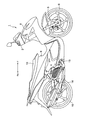
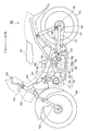
まず、図1を用いて、本実施の形態に係るハイブリッド式鞍乗型車両の全体構成を説明する。図1は、本実施の形態のハイブリッド式鞍乗型車両を示す側面図である。図2は、本実施の形態のハイブリッド式鞍乗型車両の車体カバーを外した状態の側面図である。本実施の形態のハイブリッド式鞍乗型車両は、いわゆるスポーツスクータ型の自動二輪車である。
<Configuration of hybrid straddle-type vehicle>
First, the overall configuration of the hybrid straddle-type vehicle according to the present embodiment will be described with reference to FIG. FIG. 1 is a side view showing a hybrid straddle-type vehicle according to the present embodiment. FIG. 2 is a side view of the hybrid straddle-type vehicle according to the present embodiment with the vehicle body cover removed. The hybrid straddle-type vehicle of the present embodiment is a so-called sports scooter type motorcycle.
ハイブリッド式鞍乗型車両1は、ライダーにより操舵されるハンドル2を有している。ハンドル2は、ヘッドパイプ3を挿通するステアリング軸4およびフロントフォーク5を介して、従動輪(前輪)6を操舵可能に設けられている。ヘッドパイプ3には、車体フレーム7が結合されている。
The hybrid straddle-
ヘッドパイプ3は、カウリング8によって覆われている。車体フレーム7は、車体カバー9によって覆われている。車体カバー9の上部には、シート10が配置されている。
The
車体フレーム7には、ハイブリッド式鞍乗型車両用パワーユニット(以下、単に「パワーユニット」という)12が取り付けられている。パワーユニット12は、車体フレーム7に対してピボット軸13回りに回動可能に支持されている。
A hybrid straddle-type vehicle power unit (hereinafter simply referred to as “power unit”) 12 is attached to the body frame 7. The
車体フレーム7には、スイングアーム14が揺動自在に支持されている。スイングアーム14の後端部には、駆動輪(後輪)15が回転自在に支持されている。これにより、パワーユニット12は、駆動輪15とともにピボット軸13回りにスイング可能である。
A
シート10は、ライダーが鞍乗り可能な形状のシートである。シート10の下部には、駆動用バッテリー36が配置されている。駆動用バッテリー36は、例えば、リチウムイオンバッテリーまたはニッケル水素バッテリーであり、発電機22(図3参照)または電動モータ40(図3参照)により発電された電力を蓄積する。また、駆動用バッテリー36は、駆動用の電源を電動モータ40(図3参照)に供給する。
The
<ハイブリッド式鞍乗型車両用パワーユニットの構成>
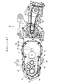
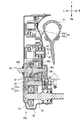
次に、図3、図4を用いて、本実施の形態に係るパワーユニット12の詳細な構成を説明する。図3は、本実施の形態に係るパワーユニット12を示す断面図である。図4は、本実施の形態に係るパワーユニット12を示す側面図である。
<Configuration of power unit for hybrid straddle type vehicle>
Next, a detailed configuration of the
パワーユニット12は、エンジントルクを発生するエンジン16と、駆動用バッテリー36の電力により電動モータトルクを発生する電動モータ40と、駆動輪15が固定される出力軸34と、エンジン16から出力軸34へエンジントルクを伝達するエンジントルク伝達経路中に設けられ、エンジントルクを増加するエンジン用減速機構90と、電動モータ40から出力軸34へ電動モータトルクを伝達する電動モータトルク伝達経路中に設けられ、電動モータトルクを増加し、増加された電動モータトルクがエンジン用減速機構90の少なくとも一部によって更に増加されて、出力軸34へ伝達されるように配置された電動モータ用減速機構91と、を備える。また、パワーユニット12は、発電機22、無段変速機23、無段変速機ケース27、ギヤケース35を備える。以下、これら各部とその周辺の構成について説明する。
The
エンジン16は、シリンダヘッド部17、シリンダボディ部18、ピストン19、コンロッド20、クランク主軸21を含む。
The
シリンダヘッド部17には、吸気の通路、排ガスの通路、吸気ポートおよび排気ポートが形成されている。吸気の通路には吸気管が接続され、排ガスの通路の下流端には排ガスを下流に流す排気管が接続される。 The cylinder head portion 17 is formed with an intake passage, an exhaust gas passage, an intake port, and an exhaust port. An intake pipe is connected to the intake passage, and an exhaust pipe for flowing the exhaust gas downstream is connected to the downstream end of the exhaust gas passage.
シリンダボディ部18は、筒状の部材である。シリンダボディ部18内には、燃焼室が形成されている。燃焼室の一方には、往復移動可能なピストン19が配置されている。ピストン19は、コンロッド20を介してクランク主軸21と接続されている。
The
クランク主軸21は、ハイブリッド鞍乗型車両1の車幅方向(ハイブリッド式鞍乗型車両1の左右方向)に延びて配置されている。クランク主軸21の右方は、発電機(ACM)22と接続されている。また、クランク主軸21の左方は、無段変速機(Continuously Variable Transmission:CVT)23のプライマリシーブ24に相対的に回転不可能なように係止されて支持されている。クランク主軸21は、減速機を介してプライマリシーブ24に接続されていてもよい。クランク主軸21とコンロッド20は、ピストン19の往復運動をクランク主軸21の回転運動に変える。
The crank
発電機22は、クランク主軸21から伝達されたトルクにより発電を行う。発電機22で発生した電力は、駆動用バッテリー36に蓄積される。
The
無段変速機23は、エンジン16の下流に設けられ、クランク主軸21からドリブン軸28へ伝達される回転運動の減速比を無段階に変更する。無段変速機23は、トランミッション部の一例に相当する。
The continuously
無段変速機23は、プライマリシーブ24、セカンダリシーブ25、ベルト26、無段変速機ケース27を含む。プライマリシーブ24およびセカンダリシーブ25は、径が可変である。無段変速機23のプライマリシーブ24、セカンダリシーブ25、およびベルト26は、無段変速機ケース27に収容されている。
The continuously
プライマリシーブ24は、クランク主軸21に相対的に回転不可能なように係止されて支持されている。
The
セカンダリシーブ25は、遠心クラッチ29の上流部材に相対的に回転不可能なように係止されて支持されている。
The
ベルト26は、プライマリシーブ24とセカンダリシーブ25とに巻き掛けられている。ベルト26は、プライマリシーブ24およびセカンダリシーブ25と連動して回転する。
The
プライマリシーブ24の回転速度が上昇すると、プライマリシーブ24の径が大きくなる一方で、セカンダリシーブ25の径が小さくなり、減速比は小さくなる。プライマリシーブ24の回転速度が低下すると、プライマリシーブ24の径が小さくなる一方で、セカンダリシーブ25の径が大きくなり、減速比は大きくなる。
As the rotational speed of the
無段変速機ケース27は、ハイブリッド式鞍乗型車両1の左方に配置される。無段変速機ケース27は、少なくとも、クランク主軸21の左方部分、無段変速機23、遠心クラッチ29、ドリブン軸28の左方部分を収容する。
The continuously
エンジン用減速機構90は、ドリブン軸28、ワンウェイクラッチ45、歯車30、歯車31、中間軸32、歯車33を含む。
The engine
ドリブン軸28は、ハイブリッド鞍乗型車両1の車幅方向に延びて配置されている。ドリブン軸28の左方には、遠心クラッチ29が設けられている。また、ドリブン軸28の右方には、ワンウェイクラッチ45が設けられている。
The driven
遠心クラッチ29は、無段変速機23の下流に配置されている。遠心クラッチ29は、下流部材と上流部材とを有し、上流部材の回転速度に応じて、切断と接続が切り替わる。遠心クラッチ29の上流部材は、セカンダリシーブ25に相対的に回転不可能なように係止されて支持され、遠心クラッチ29の下流部材は、ドリブン軸28に相対的に回転不可能なように係止されて支持されている。
The centrifugal clutch 29 is disposed downstream of the continuously
ワンウェイクラッチ45は、ドリブン軸28と、歯車30および歯車44との間に配置されている。図3の例では、ワンウェイクラッチ45は、ニードル型のワンウェイクラッチである。歯車30および歯車44は、同心軸上に径の異なる2つの平歯車が互いに固定された2段歯車であり、ワンウェイクラッチ45に固定されている。歯車30の歯車軸と歯車44の歯車軸とは、互いに平行である。
The one-way clutch 45 is disposed between the driven
ワンウェイクラッチ45は、外輪部に対する内輪部(例えばドリブン軸28)の回転方向によって、切断と接続が切り替わる。これにより、ドリブン軸28から出力軸34へエンジントルクが伝達される場合、ワンウェイクラッチ45がドリブン軸28と歯車30および歯車44とを接続する。一方、エンジントルクが低下し、歯車30および歯車44の回転速度がドリブン軸28の回転速度よりも大きくなったときには、ワンウェイクラッチ45がドリブン軸28と歯車30および歯車44とを切断する。これにより、出力軸34からのトルクは、ドリブン軸28へ伝わらない。
The one-way clutch 45 is switched between cutting and connection depending on the rotation direction of the inner ring portion (for example, the driven shaft 28) with respect to the outer ring portion. Thereby, when engine torque is transmitted from the driven
歯車30は、歯車31の大歯車31aと組み合っている。
The
歯車31は、中間軸32に固定されている。歯車31は、例えば、同心軸上に径の異なる2つの平歯車が互いに固定された2段歯車である。すなわち、歯車31では、所定の径を有する大歯車31aと、大歯車31aの径よりも小さい径を同心軸上に有する小歯車31bとが互いに固定されている。大歯車31aは、歯車30と組み合っている。小歯車31bは、歯車33と組み合っている。
The
歯車33は、出力軸34に固定されている。歯車33は、例えば、平歯車であり、歯車31の小歯車31bと組み合っている。
The
出力軸34は、駆動輪15に固定されている。
The
このように、エンジン用減速機構90は、互いに回転軸が異なる歯車30、歯車31、歯車33を備えた3軸歯車機構を含む。
As described above, the engine
本実施の形態では、エンジントルクがエンジン16から出力軸34へ伝達される経路を「エンジントルク伝達経路」という。図3、図4の例では、エンジントルク伝達経路は、クランク主軸21、無段変速機23、ドリブン軸28、歯車30、歯車31、中間軸32、歯車33、出力軸34により構成される。エンジン16で発生したエンジントルクは、クランク主軸21、無段変速機23、ドリブン軸28、ワンウェイクラッチ45、歯車30、歯車31、中間軸32、歯車33、出力軸34、駆動輪15の順に伝達される。
In the present embodiment, a path through which engine torque is transmitted from the
電動モータ40は、ハイブリッド式鞍乗型車両1の車幅方向において、駆動輪15と無段変速機23との間に配置されている。なお、図3の例では、電動モータ40の全体が、駆動輪15と無段変速機23との間に配置される構成としたが、電動モータ40の少なくとも一部が駆動輪15と無段変速機23との間に配置されればよい。また、電動モータ40は、無段変速機23とともに、無段変速機ケース27内に配置されてもよい。
The
電動モータ40は、電動モータトルクを発生するモータ本体部40aと、電動モータトルクにより回転する電動モータ軸40bと、を含む。
The
電動モータ用減速機構91は、電動モータ軸歯車42、歯車43、歯車44を含む。
The electric motor
電動モータ軸歯車42は、例えば、平歯車であり、電動モータ用減速機構91の歯車43と組み合っている。
The electric
歯車43は、例えば、軸部41を備えた平歯車であり、軸部41を中心として回転可能に支持されている。歯車43は、一部が電動モータ軸歯車42と組み合っており、他の一部が歯車44と組み合っている。
The
歯車44は、エンジン用減速機構90の歯車30とともに2段歯車を構成している。
The
ギヤケース35は、ハイブリッド式鞍乗型車両1の車幅方向において、駆動輪15と無段変速機23との間に配置される。ギヤケース35は、少なくとも、電動モータ40、電動モータ用減速機構91、エンジン用減速機構90(ただし、ドリブン軸28の左方部分を除く)、出力軸34の左方部分を収容する。ギヤケース35内には、潤滑油としてのオイルが入っている。オイルは、歯車30、31、33、43、44の回転に伴って掻き上げられ、ギヤケース35内に飛散する。飛散したオイルは、歯車30、31、33、43、44およびワンウェイクラッチ45を潤滑する。
The
本実施の形態では、電動モータトルクが電動モータ40から出力軸34へ伝達される経路を「電動モータトルク伝達経路」という。図3、図4の例では、電動モータトルク伝達経路は、電動モータ軸40b、電動モータ軸歯車42、歯車43、歯車44、ドリブン軸28、歯車30、歯車31、中間軸32、歯車33、出力軸34により構成される。
In the present embodiment, a path through which the electric motor torque is transmitted from the
電動モータ40で発生した電動モータトルクは、電動モータ軸40b、電動モータ軸歯車42、歯車43、歯車44、歯車30、歯車31、中間軸32、歯車33、出力軸34、駆動輪15の順に伝達される。すなわち、電動モータトルクは、電動モータ用減速機構91により増加された後、さらにエンジン用減速機構90により増加されて、駆動輪15に出力される。
The electric motor torque generated by the
ハイブリッド式鞍乗型車両1の制動時など、出力軸34で発生したトルクは、歯車33、歯車31および中間軸32、歯車30、歯車44、歯車43、電動モータ軸歯車42、電動モータ軸40b、電動モータ40の順に伝達される。このトルクの伝達により、制動時の回生エネルギーを電動モータ40により回収できる。
The torque generated in the
以上、本実施の形態に係るパワーユニット12の構成について説明したが、パワーユニット12は、以下の構成であってもよい。
The configuration of the
図3、図4の例では、電動モータ用減速機構91の歯車44が、エンジン用減速機構90の歯車30に直接接続される構成としたが、電動モータ用減速機構91は、出力軸34および出力軸34に最も近い歯車33を除くエンジン用減速機構90の構成要素(例えば、ドリブン軸28、中間軸32、歯車30、歯車31)のいずれかに直接接続されればよい。
3 and 4, the
図3、図4の例では、ニードル型のワンウェイクラッチ45を備える構成としたが、これに限定されない。図5、図6を用いて別の構成例をそれぞれ説明する。 In the example of FIGS. 3 and 4, the needle type one-way clutch 45 is provided. However, the present invention is not limited to this. Another configuration example will be described with reference to FIGS. 5 and 6.
まず、図5の構成例について説明する。図5の例では、エンジン用減速機構90aは、ドリブン軸46、ワンウェイクラッチ47、歯車30a、歯車31、中間軸32、歯車33を含む。図5の例では、エンジン用減速機構91aは、歯車43、歯車44aを含む。図5の例では、歯車44aは、歯車30aに固定されておらず、歯車44aおよび歯車30aのそれぞれがドリブン軸46(後述の右方軸46a)に固定されている。
First, the configuration example of FIG. 5 will be described. In the example of FIG. 5, the engine
ドリブン軸46は、鞍乗型車両1の車幅方向の右方に配置される右方軸46aと、鞍乗型車両1の車幅方向の左方に配置される左方軸46bとを含む。
The driven
ワンウェイクラッチ47は、ドリブン軸46の左方軸46bと右方軸46aとの間に配置されている。ワンウェイクラッチ47は、外輪部に対する内輪部の回転方向によって、切断と接続が切り替わる。外輪部は、左方軸46bに固定されている。内輪部は右方軸46aに固定されている。これにより、ドリブン軸46から出力軸34へエンジントルクが伝達される場合、ワンウェイクラッチ47が左方軸46bと右方軸46aとを接続する。この場合、エンジントルクは、ドリブン軸46の左方軸46b、ドリブン軸46の右方軸46a、歯車30a、歯車31、中間軸32、歯車33、出力軸34、駆動輪15の順に伝達される。
The one-way clutch 47 is disposed between the
一方、エンジントルクが低下し、右方軸46aの回転速度が左方軸46bの回転速度よりも大きくなったときには、ワンウェイクラッチ47が左方軸46bと右方軸46aとを切断する。これにより、出力軸34からのトルクは、ドリブン軸46の左方軸46bへ伝わらない。この場合、出力軸34からのトルクは、出力軸34、歯車33、歯車31、中間軸32、歯車30a、ドリブン軸46の右方軸46a、歯車44a、歯車43、モータ軸歯車42、電動モータ軸40b、電動モータ40の順に伝達される。
On the other hand, when the engine torque decreases and the rotational speed of the
次に、図6の構成例について説明する。図6の例では、エンジン用減速機構90bは、ドリブン軸48、ニードルベアリング49、歯車50、歯車51、歯車52、歯車53、中間軸32、ワンウェイクラッチ54、歯車55を含む。図6の例では、電動モータ用減速機構91bは、歯車43、歯車44b、歯車44cを含む。
Next, the configuration example of FIG. 6 will be described. In the example of FIG. 6, the engine
歯車44bおよび歯車44cは、同心軸上に径の異なる2つの平歯車が互いに固定された2段歯車である。歯車44bおよび歯車44cは、ニードルベアリング49を介して、ドリブン軸48に空転可能に支持されている。歯車44cは、歯車51と組み合っている。
The
歯車50は、例えば、平歯車であり、ドリブン軸48に固定されている。歯車50は、歯車52と組み合っている。
The
歯車51、歯車52、歯車53は、例えば、平歯車であり、中間軸32に固定されている。歯車51は、歯車30と組み合っている。歯車52は、歯車50と組み合っている。歯車53は、歯車55と組み合っている。
The
歯車55は、例えば、平歯車であり、出力軸34に固定されている。歯車55は、歯車53と組み合っている。
The
ワンウェイクラッチ54は、歯車52の内部に配置されている。ワンウェイクラッチ54は、外輪部に対する内輪部の回転方向によって、切断と接続が切り替わる。図6の例では、歯車52は、外輪部52aと内輪部52bを有する。これにより、ドリブン軸48から出力軸34へエンジントルクが伝達される場合、ワンウェイクラッチ54が外輪部52aと内輪部52bとを接続する。この場合、エンジントルクは、ドリブン軸48、歯車50、歯車52、中間軸32、歯車53、歯車55、出力軸34、駆動輪15の順に伝達される。
The one-way clutch 54 is disposed inside the
一方、エンジントルクが低下し、ドリブン軸48および歯車50の回転速度が中間軸32および歯車52の回転速度よりも大きくなったときには、ワンウェイクラッチ54が外輪部52aと内輪部52bとを切断する。これにより、出力軸34からのトルクは、ドリブン軸48へ伝わらない。この場合、出力軸34からのトルクは、出力軸34、歯車55、歯車53、中間軸32、歯車51、歯車30、歯車40、歯車43、モータ軸歯車42、電動モータ軸40b、電動モータ40の順に伝達される。
On the other hand, when the engine torque decreases and the rotational speed of the driven
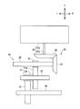
また、図3、図4の例では、電動モータ用減速機構91が平歯車である歯車43、44を含む構成としたが、電動モータ用減速機構を構成する歯車は平歯車に限定されない。例えば、図7に示すように、電動モータ用減速機構95は、傘歯車である歯車60、61を含む構成でもよい。歯車60は、電動モータ軸40bに固定されており、歯車61と組み合っている。歯車61は、エンジン用減速機構を構成するドリブン軸28に固定されており、歯車60と組み合っている。なお、図7の例では、電動モータ用減速機構95は、エンジン用減速機構を構成する軸に固定される傘歯車を含む構成としたが、エンジン用減速機構を構成する歯車に直接接続される傘歯車を含む構成であってもよい。
3 and 4, the electric motor
<実施の形態1の効果>
実施の形態1のハイブリッド式鞍乗型車両用パワーユニット12は、エンジン16から出力軸34へエンジントルクを伝達するエンジントルク伝達経路中に設けられ、エンジントルクを増加して出力軸34へ伝達するエンジン用減速機構90と、電動モータ40から出力軸34へ電動モータトルクを伝達する電動モータトルク伝達経路中に設けられ、電動モータトルクを増加し、増加された電動モータトルクがエンジン用減速機構90の少なくとも一部(例えば、歯車30)によって更に増加されて、出力軸34へ伝達されるように配置された電動モータ用減速機構91と、を備える。これにより、小さい電動モータ用減速機構91であっても、減速機構全体として大きな減速比を得ることができる。その分、電動モータ40を小型化することが可能となる。また、エンジン用減速機構90を一部流用しているため、減速機構全体としてみれば大型化を抑制できる。さらに、電動モータ用減速機構91を設けることで、エンジン用減速機構90に対して、電動モータ40の配置場所の自由度が向上する。これにより、スペースを確保することが困難なエンジン用減速機構90の周囲でも、大型化を抑制できる適宜な場所に電動モータ40を配置し易くなる。よって、エンジン用減速機構90の周囲に電動モータ40を配置してもハイブリッド式鞍乗型車両1の大型化を抑制できる。
<Effect of
The hybrid straddle-type
よって、実施の形態1によれば、エンジン16に加えて電動モータ40を搭載しても、ハイブリッド式鞍乗型車両1の大型化を抑制できるハイブリッド式鞍乗型車両用パワーユニット12を提供できる。
Therefore, according to the first embodiment, even if the
実施の形態1のハイブリッド式鞍乗型車両用パワーユニット12では、電動モータ用減速機構91(例えば、歯車44)がエンジン用減速機構90(例えば、歯車30)と直接接続している。
In the hybrid straddle-type
よって、実施の形態1によれば、電動モータ用減速機構91およびエンジン用減速機構90をさらにコンパクトに構成できる。よって、エンジン用減速機構90の周囲に電動モータ40を配置してもハイブリッド式鞍乗型車両1の大型化を抑制できる。従って、エンジン16に加えて電動モータ40を搭載しても、ハイブリッド式鞍乗型車両1の大型化を抑制できるハイブリッド式鞍乗型車両用パワーユニット12を提供できる。
Therefore, according to the first embodiment, the electric motor
実施の形態1のハイブリッド式鞍乗型車両用パワーユニット12は、エンジントルクをエンジン16から出力軸34へ伝達し、出力軸34からのトルクを出力軸34からエンジン16へ伝達しないようにするワンウェイクラッチ45をさらに備え、電動モータ用減速機構91は、ワンウェイクラッチ45と出力軸34との間で、エンジン用減速機構90と直接接続している。
The hybrid straddle-type
よって、実施の形態1によれば、出力軸34からのトルクをエンジン16へ伝達せずに電動モータ40へ伝達することができる。一般的に、燃費向上のためには、電動モータが一定以上の回生エネルギーを確保することが必要である。その対策としては、例えば、強力な磁石にする方法、磁石の寸法を大きくする方法、コイル線を太くして巻き数を増加する方法、あるいは、電動モータの動作電圧を増加させる方法などがある。しかし、これらの方法は、コストの増加または電動モータ(または、例えば電動モータの制御システム)の大型化を招く。よって、実施の形態1によれば、上述した方法を採ることなく、電動モータ40がワンウェイクラッチを備えない場合と比べてより多くの回生エネルギーを確保できる。従って、エンジン16に加えて電動モータ40を搭載しても、ハイブリッド式鞍乗型車両1の大型化を抑制できるハイブリッド式鞍乗型車両用パワーユニット12を提供できる。
Therefore, according to the first embodiment, torque from the
実施の形態1のハイブリッド式鞍乗型車両用パワーユニット12では、電動モータ用減速機構91が、エンジン用減速機構90を構成するドリブン軸28に固定される歯車、または、エンジン用減速機構を構成する歯車30に直接接続される歯車44を含む。
In the hybrid straddle-type
よって、実施の形態1によれば、電動モータ用減速機構91およびエンジン用減速機構90をさらにコンパクトに構成できる。よって、エンジン用減速機構90の周囲に電動モータ40を配置してもハイブリッド式鞍乗型車両1の大型化を抑制できる。従って、エンジン16に加えて電動モータを搭載しても、ハイブリッド式鞍乗型車両1の大型化を抑制できるハイブリッド式鞍乗型車両用パワーユニット12を提供できる。
Therefore, according to the first embodiment, the electric motor
実施の形態1のハイブリッド式鞍乗型車両用パワーユニット12では、電動モータ用減速機構91を構成する平歯車である歯車44の軸は、エンジン用減速機構90を構成する平歯車である歯車30の軸と平行である。
In the hybrid straddle-type
よって、実施の形態1によれば、平歯車である歯車44、30の軸方向に垂直な方向において電動モータ40の配置場所の自由度が高まるので、電動モータ用減速機構91およびエンジン用減速機構90をさらにコンパクトに構成できる。よって、エンジン用減速機構90の周囲に電動モータ40を配置してもハイブリッド式鞍乗型車両1の大型化を抑制できる。従って、エンジン16に加えて電動モータを搭載しても、ハイブリッド式鞍乗型車両1の大型化を抑制できるハイブリッド式鞍乗型車両用パワーユニット12を提供できる。
Therefore, according to the first embodiment, the degree of freedom of the location of the
実施の形態1のハイブリッド式鞍乗型車両用パワーユニット12では、エンジン用減速機構90は、互いに回転軸が異なる平歯車である歯車30、31、33を備えた3軸歯車機構であり、電動モータ用減速機構91を構成する平歯車である歯車44は、3軸歯車機構のうちエンジントルク伝達経路中にある歯車30に直接接続される。
In the hybrid straddle-type
よって、実施の形態1によれば、電動モータ用減速機構91およびエンジン用減速機構90をさらにコンパクトに構成できる。よって、エンジン用減速機構90の周囲に電動モータ40を配置してもハイブリッド式鞍乗型車両1の大型化を抑制できる。従って、エンジン16に加えて電動モータ40を搭載しても、ハイブリッド式鞍乗型車両1の大型化を抑制できるハイブリッド式鞍乗型車両用パワーユニット12を提供できる。
Therefore, according to the first embodiment, the electric motor
実施の形態1のハイブリッド式鞍乗型車両用パワーユニット12では、エンジン用減速機構90は、同心軸上に径の異なる2つの平歯車が互いに固定された2段歯車である歯車31を含む。
In the hybrid straddle-type
よって、実施の形態1によれば、エンジン用減速機構90をよりコンパクトに構成できる。よって、エンジン用減速機構90の周囲に電動モータ40を配置してもハイブリッド式鞍乗型車両1の大型化を抑制できる。従って、エンジン16に加えて電動モータ40を搭載しても、ハイブリッド式鞍乗型車両1の大型化を抑制できるハイブリッド式鞍乗型車両用パワーユニット12を提供できる。
Therefore, according to
実施の形態1のハイブリッド式鞍乗型車両用パワーユニット12では、電動モータ用減速機構91は、エンジントルク伝達経路において遠心クラッチ29の下流に設けられたエンジン用減速機構90の少なくとも一部(例えば、歯車30)と直接接続している。
In the hybrid straddle-type
よって、実施の形態1によれば、エンジン16から出力軸34までのトルク伝達機構、電動モータ用減速機構91およびエンジン用減速機構90をさらにコンパクトにできる。よって、エンジン用減速機構90の周囲に電動モータ40を配置してもハイブリッド式鞍乗型車両1の大型化を抑制できる。従って、エンジン16に加えて電動モータ40を搭載しても、ハイブリッド式鞍乗型車両1の大型化を抑制できるハイブリッド式鞍乗型車両用パワーユニット12を提供できる。
Therefore, according to the first embodiment, the torque transmission mechanism from the
実施の形態1のハイブリッド式鞍乗型車両用パワーユニット12では、電動モータ40の少なくとも一部は、出力軸34に固定される駆動輪15と無段変速機23のベルト26との間に配置されている。
In the hybrid straddle-type
よって、実施の形態1によれば、スペースを確保することが困難なエンジン用減速機構90の周囲において、ハイブリッド式鞍乗型車両1の大型化が抑制されるように電動モータ40を配置できる。従って、エンジン16に加えて電動モータ40を搭載しても、ハイブリッド式鞍乗型車両1の大型化を抑制できるハイブリッド式鞍乗型車両用パワーユニット12を提供できる。
Therefore, according to the first embodiment, the
実施の形態1のハイブリッド式鞍乗型車両用パワーユニット12では、電動モータ40は、無段変速機23の無段変速機ケース27内に配置されている。
In the hybrid straddle-type
よって、実施の形態1によれば、スペースを確保することが困難なエンジン用減速機構90の周囲において、ハイブリッド式鞍乗型車両1の大型化が抑制されるように電動モータ40を配置できる。従って、エンジン16に加えて電動モータ40を搭載しても、ハイブリッド式鞍乗型車両1の大型化を抑制できるハイブリッド式鞍乗型車両用パワーユニット12を提供できる。
Therefore, according to the first embodiment, the
実施の形態1のハイブリッド式鞍乗型車両用パワーユニット12は、エンジン16の往復運動を受けて回転するクランク主軸21と、クランク主軸21に接続された発電機22と、をさらに備える。
The hybrid straddle-type
よって、実施の形態1によれば、ハイブリッド式鞍乗型車両1の走行中に電動モータ40により発電される電力と発電機22により発電される電力の両方を得ることができるので、電動モータ40および発電機22を小型化できる。電動モータ40および発電機22の両方を小型化することで電動モータ40および発電機22の配置場所の自由度が向上するので、エンジン用減速機構90の周囲に、クランク主軸21に接続される発電機22とは別の構成である電動モータ40を配置してもハイブリッド式鞍乗型車両1の大型化を抑制できる。よって、エンジン16に加えて電動モータ40を搭載しても、ハイブリッド式鞍乗型車両1の大型化を抑制できるハイブリッド式鞍乗型車両用パワーユニット12を提供できる。
Therefore, according to the first embodiment, it is possible to obtain both the electric power generated by the
実施の形態1のハイブリッド式鞍乗型車両用パワーユニット12では、電動モータ用減速機構95は、エンジン用減速機構90を構成するドリブン軸28に固定される傘歯車61、または、エンジン用減速機構90を構成する歯車に直接接続される傘歯車を含む。
In the hybrid straddle-type
よって、実施の形態1によれば、エンジン用減速機構90と接続される傘歯車61の軸を中心とした周方向において電動モータの配置場所の自由度が高まるので、電動モータ用減速機構91およびエンジン用減速機構90をさらにコンパクトに構成できる。よって、エンジン用減速機構90の周囲に電動モータ40を配置してもハイブリッド式鞍乗型車両1の大型化を抑制できる。従って、エンジン16に加えて電動モータ40を搭載しても、ハイブリッド式鞍乗型車両1の大型化を抑制できるハイブリッド式鞍乗型車両用パワーユニット12を提供できる。
Therefore, according to the first embodiment, since the degree of freedom of the arrangement location of the electric motor increases in the circumferential direction around the axis of the
実施の形態1のハイブリッド式鞍乗型車両1は、ハイブリッド式鞍乗型車両用パワーユニット12と、ハイブリッド式鞍乗型車両用パワーユニット12の電動モータ40に駆動用の電源を供給する駆動用バッテリー36と、出力軸34に固定されて駆動される駆動輪15と、を備える。
The hybrid straddle-
よって、実施の形態1によれば、ハイブリッド式鞍乗型車両1の大型化を抑制できるハイブリッド式鞍乗型車両用パワーユニット12を適用することで、エンジン16に加えて電動モータ40と駆動用バッテリー36とを搭載しても、ハイブリッド式鞍乗型車両1の大型化を抑制できるハイブリッド式鞍乗型車両1を提供できる。
Therefore, according to the first embodiment, by applying the hybrid straddle-type
(実施の形態2)
本発明の実施の形態2を説明する。
(Embodiment 2)
A second embodiment of the present invention will be described.
<ハイブリッド式鞍乗型車両の構成>
まず、図8を用いて、本実施の形態に係るハイブリッド式鞍乗型車両の全体構成を説明する。図8は、本実施の形態のハイブリッド式鞍乗型車両を示す側面図である。本実施の形態のハイブリッド式鞍乗型車両は、いわゆるアンダーボーン型の自動二輪車である。
<Configuration of hybrid straddle-type vehicle>
First, the overall configuration of the hybrid straddle-type vehicle according to the present embodiment will be described with reference to FIG. FIG. 8 is a side view showing the hybrid straddle-type vehicle of the present embodiment. The hybrid straddle-type vehicle according to the present embodiment is a so-called underbone type motorcycle.
ハイブリッド式鞍乗型車両100は、ライダーにより操舵されるハンドル102を有している。ハンドル102は、ヘッドパイプ103を挿通するステアリング軸104およびフロントフォーク105を介して、従動輪(前輪)106を操舵可能に設けられている。ヘッドパイプ103には、車体フレーム107が結合されている。
The hybrid straddle-
車体フレーム107は、車体カバー109によって覆われている。車体カバー109の上部には、シート110が配置されている。
The
車体フレーム107には、ハイブリッド式鞍乗型車両用パワーユニット(以下、単に「パワーユニット」という)112が取り付けられている。パワーユニット112は、車体フレーム107に対してピボット軸113回りに回動可能に支持されている。
A hybrid straddle-type vehicle power unit (hereinafter simply referred to as “power unit”) 112 is attached to the
車体フレーム107には、スイングアーム114が揺動自在に支持されている。スイングアーム114の後端部には、駆動輪(後輪)115が回転自在に支持されている。これにより、パワーユニット112は、駆動輪115とともにピボット軸113回りにスイング可能である。
A
シート110は、ライダーが鞍乗り可能な形状のシートである。シート110の下部には、駆動用バッテリー136が配置されている。駆動用バッテリー136は、例えば、リチウムイオンバッテリーまたはニッケル水素バッテリーであり、パワーユニット112内の発電機(図示略)または電動モータ140により発電された電力を蓄積する。また、駆動用バッテリー136は、駆動用の電源を電動モータ140に供給する。
The
<ハイブリッド式鞍乗型車両用パワーユニットの構成>
次に、図8を用いて、本実施の形態に係るパワーユニット112の詳細な構成を説明する。
<Configuration of power unit for hybrid straddle type vehicle>
Next, the detailed configuration of the
パワーユニット112は、エンジン116、電動モータ140、トランスミッション部123、出力軸134、エンジン用減速機構190、電動モータ用減速機構191を有する。
The
エンジン116は、シリンダヘッド部117、シリンダボディ部118、クランク主軸125を有する。シリンダヘッド部117、シリンダボディ部118、クランク主軸125は、実施の形態1で説明したシリンダヘッド部17、シリンダボディ部18、クランク主軸21と同様の機能を有するため、ここでの詳細な説明は省略する。クランク主軸125は、エンジン116で発生したエンジントルクを、トランスミッション部123を介してエンジン用減速機構190の上流回転体119へ伝達する。
The
トランスミッション部123は、クランク主軸125からエンジン用減速機構190の上流回転体119へ伝達されるエンジントルクの減速比を変更する。
The
エンジン用減速機構190は、上流回転体119、下流回転体120、長尺部材121を有する。
The
上流回転体119は、径の異なる2つの回転体、すなわち、回転体119aと回転体119bとが固定されたものである。回転体119a、回転体119bは、例えば、スプロケットである。
The upstream
下流回転体120は、上流回転体119と径の異なる回転体である。下流回転体120は、駆動輪115に固定された出力軸134に接続されている。下流回転体120は、例えば、スプロケットである。
The downstream
長尺部材121は、上流回転体119の回転体119aと、下流回転体120とに巻き掛けられた部材である。長尺部材121は、例えば、チェーンである。
The
このような巻き掛け機構であるエンジン用減速機構190は、クランク主軸125からトランスミッション部123を介して上流回転体119の回転体119aへ伝達されたエンジントルクを、長尺部材121を介して下流回転体120および出力軸134に伝達する。
The engine
本実施の形態では、エンジントルクがエンジン116から出力軸134へ伝達される経路を「エンジントルク伝達経路」という。図8の例では、エンジントルク伝達経路は、クランク主軸125、トランスミッション部123、上流回転体119、長尺部材121、下流回転体120により構成される。
In the present embodiment, a path through which engine torque is transmitted from
電動モータ140は、実施の形態1で説明した電動モータ40と同様の機能を有するため、ここでの詳細な説明は省略する。電動モータ140で発生した電動モータトルクは、電動モータ用減速機構191によりエンジン用減速機構190に伝達され、駆動輪115に伝達される。
Since the
電動モータ用減速機構191は、電動モータ用回転体143、長尺部材145を有する。
The electric motor
電動モータ用回転体143は、電動モータ140の電動モータ軸(図示略)と接続されている。電動モータ用回転体143は、例えば、スプロケットである。
The electric
長尺部材145は、電動モータ用回転体143と、上流回転体119の回転体119bとに巻き掛けられた部材である。長尺部材145は、例えば、チェーンである。
The
このような巻き掛け機構である電動モータ用減速機構191は、エンジン用減速機構190に直接接続している。この構成により、電動モータ140で発生した電動モータトルクは、電動モータ用減速機構191の電動モータ用回転体143から長尺部材145を介して上流回転体119の回転体119bへ伝達される。回転体119bへ伝達された電動モータトルクは、回転体119a、長尺部材121、および下流回転体120を介して、出力軸134へと伝達される。すなわち、電動モータトルクは、電動モータ用減速機構191により増加された後、さらにエンジン用減速機構190により増加されて、駆動輪115に出力される。
The electric motor
本実施の形態では、電動モータトルクが電動モータ140から出力軸134へ伝達される経路を「電動モータトルク伝達経路」という。図8の例では、電動モータトルク伝達経路は、電動モータ軸(図示略)、電動モータ用回転体143、長尺部材145、上流回転体119、長尺部材121、下流回転体120により構成される。
In the present embodiment, a path through which the electric motor torque is transmitted from the
以上、本実施の形態に係るパワーユニット112の構成について説明したが、パワーユニット112は、以下の構成であってもよい。
The configuration of the
図8の例では、長尺部材145は、電動モータ用回転体143と上流回転体119との間に巻き掛けられるとしたが、これに限定されない。例えば、長尺部材145は、電動モータ用回転体143と下流回転体120との間に巻き掛けられてもよい。その場合、下流回転体120は、図8に示した上流回転体119と同様に、径の異なる2つの回転体を備え、それらのうちの1つは長尺部材121が巻き掛けられ、もう1つは長尺部材145が巻き掛けられる構成を採る。
In the example of FIG. 8, the
また、上記説明では、上流回転体119、下流回転体120、電動モータ用回転体143がスプロケットであり、長尺部材121、長尺部材145がチェーンであるとしたが、これに限定されない。例えば、上流回転体119、下流回転体120、電動モータ用回転体143がシーブであり、長尺部材121、長尺部材145がベルトであってもよい。
In the above description, the upstream
パワーユニット112は、エンジントルクをエンジン116から出力軸134へ伝達し、出力軸134からのトルクを出力軸134からエンジン116へ伝達しないようにするワンウェイクラッチをさらに備えてもよい。この場合、電動モータ用減速機構191は、ワンウェイクラッチと出力軸134との間で、エンジン用減速機構190と直接接続されればよい。
The
パワーユニット112は、エンジントルク伝達経路においてトランスミッション部123の下流に設けられ、エンジントルクの伝達を遠心力により接続または切断する遠心式クラッチをさらに備えてもよい。この場合、電動モータ用減速機構191は、エンジントルク伝達経路において遠心式クラッチの下流に設けられたエンジン用減速機構190の少なくとも一部(例えば、上流回転体119または下流回転体120)と直接接続されればよい。
The
パワーユニット112は、エンジントルク伝達経路においてエンジン116とエンジン用減速機構190との間に設けられ、径が可変なシーブと、シーブに組み合わされてエンジントルクを伝達するベルトとを有し、エンジントルクの減速比を無段階に変更する無段変速機をさらに備えてもよい。この場合、電動モータ140の少なくとも一部は、出力軸134に固定される駆動輪115と無段変速機のベルトとの間に配置されればよい。
The
パワーユニット112は、無段変速機のシーブおよびベルトを収容する無段変速機ケースをさらに備えてもよい。この場合、電動モータ140は、無段変速機ケース内に配置されてもよい。
The
パワーユニット112は、クランク主軸125に接続された発電機をさらに備えてもよい。
The
<実施の形態2の効果>
実施の形態2のハイブリッド式鞍乗型車両用パワーユニット112は、エンジン116から出力軸134へエンジントルクを伝達するエンジントルク伝達経路中に設けられ、エンジントルクを増加して出力軸134へ伝達するエンジン用減速機構190と、電動モータ140から出力軸134へ電動モータトルクを伝達する電動モータトルク伝達経路中に設けられ、電動モータトルクを増加し、増加された電動モータトルクがエンジン用減速機構190の少なくとも一部(例えば、上流回転体119)によって更に増加されて、出力軸134へ伝達されるように配置された電動モータ用減速機構191と、を備える。これにより、小さい電動モータ用減速機構191であっても、減速機構全体として大きな減速比を得ることができる。その分、電動モータ140を小型化することが可能となる。また、エンジン用減速機構190を一部流用しているため、減速機構全体としてみれば大型化を抑制できる。さらに、電動モータ用減速機構191を設けることで、エンジン用減速機構190に対して、電動モータ140の配置場所の自由度が向上する。これにより、スペースを確保することが困難なエンジン用減速機構190の周囲でも、大型化を抑制できる適宜な場所に電動モータ140を配置し易くなる。よって、エンジン用減速機構190の周囲に電動モータ140を配置してもハイブリッド式鞍乗型車両100の大型化を抑制できる。
<Effect of
The hybrid straddle-type
よって、実施の形態2によれば、エンジン116に加えて電動モータ140を搭載しても、ハイブリッド式鞍乗型車両100の大型化を抑制できるハイブリッド式鞍乗型車両用パワーユニット112を提供できる。
Therefore, according to the second embodiment, it is possible to provide the hybrid straddle-type
実施の形態2のハイブリッド式鞍乗型車両用パワーユニット112では、電動モータ用減速機構191(例えば、長尺部材145)がエンジン用減速機構190(例えば、回転体119b)と直接接続している。
In the hybrid straddle-type
よって、実施の形態2によれば、電動モータ用減速機構191およびエンジン用減速機構190をさらにコンパクトに構成できる。よって、エンジン用減速機構190の周囲に電動モータ140を配置してもハイブリッド式鞍乗型車両100の大型化を抑制できる。従って、エンジン116に加えて電動モータ140を搭載しても、ハイブリッド式鞍乗型車両100の大型化を抑制できるハイブリッド式鞍乗型車両用パワーユニット112を提供できる。
Therefore, according to the second embodiment, the electric motor
実施の形態2のハイブリッド式鞍乗型車両用パワーユニット112では、エンジン用減速機構190は、上流回転体119と、上流回転体119と径が異なり出力軸134に固定される下流回転体120と、上流回転体119と下流回転体120との間に巻き掛けられる長尺部材121とを有し、上流回転体119に加えられたエンジントルクが長尺部材121を介して下流回転体120に伝達される巻き掛け機構であり、電動モータ用減速機構191は、巻き掛け機構を含むエンジン用減速機構119の少なくとも一部(例えば、上流回転体119の回転体119a)に接続している。
In the hybrid straddle-type
よって、実施の形態2によれば、電動モータ用減速機構191およびエンジン用減速機構190をさらにコンパクトにできる。よって、エンジン用減速機構190の周囲に電動モータ140を配置してもハイブリッド式鞍乗型車両100の大型化を抑制できる。従って、エンジン116に加えて電動モータ140を搭載しても、ハイブリッド式鞍乗型車両100の大型化を抑制できるハイブリッド式鞍乗型車両用パワーユニット112を提供できる。
Therefore, according to the second embodiment, the electric motor
実施の形態2のハイブリッド式鞍乗型車両100は、ハイブリッド式鞍乗型車両用パワーユニット112と、ハイブリッド式鞍乗型車両用パワーユニット112の電動モータ140に駆動用の電源を供給する駆動用バッテリー136と、出力軸134に固定されて駆動される駆動輪115と、を備える。
A hybrid straddle-
よって、実施の形態2によれば、ハイブリッド式鞍乗型車両100の大型化を抑制できるハイブリッド式鞍乗型車両用パワーユニット112を適用することで、エンジン116に加えて電動モータ140と駆動用バッテリー136とを搭載しても、ハイブリッド式鞍乗型車両100の大型化を抑制できるハイブリッド式鞍乗型車両100を提供できる。
Therefore, according to the second embodiment, by applying the hybrid straddle-type
以上、本発明の各実施の形態について説明した。 The embodiments of the present invention have been described above.
本発明は、多くの異なった形態で具現化され得るものである。この開示は本発明の原理の実施の形態を提供するものと見なされるべきである。それらの実施の形態は、本発明をここに記載しかつ/または図示した好ましい実施の形態に限定することを意図するものではないという了解のもとで、多くの図示実施の形態がここに記載されている。 The present invention can be embodied in many different forms. This disclosure is to be considered as providing an embodiment of the principles of the invention. Many illustrated embodiments are described herein with the understanding that these embodiments are not intended to limit the invention to the preferred embodiments described and / or illustrated herein. Has been.
本発明の図示実施の形態を幾つかここに記載した。本発明は、ここに記載した各種の好ましい実施の形態に限定されるものではない。本発明は、この開示に基づいて当業者によって認識され得る、均等な要素、修正、削除、組み合わせ(例えば、各種実施の形態に跨る特徴の組み合わせ)、改良および/または変更を含むあらゆる実施の形態をも包含する。クレームの限定事項はそのクレームで用いられた用語に基づいて広く解釈されるべきであり、本明細書あるいは本願のプロセキューション中に記載された実施の形態に限定されるべきではない。そのような実施の形態は非排他的であると解釈されるべきである。例えば、この開示において、「好ましくは」や「よい」という用語は非排他的なものであって、「好ましいがこれに限定されるものではない」や「よいがこれに限定されるものではない」ということを意味するものである。 Several illustrative embodiments of the invention have been described herein. The present invention is not limited to the various preferred embodiments described herein. The present invention can be recognized by those skilled in the art based on this disclosure, in any embodiment including equivalent elements, modifications, deletions, combinations (for example, combinations of features across various embodiments), improvements, and / or changes. Is also included. Claim limitations should be construed broadly based on the terms used in the claims and should not be limited to the embodiments described herein or in the process of this application. Such an embodiment should be construed as non-exclusive. For example, in this disclosure, the terms “preferably” and “good” are non-exclusive, and “preferably but not limited to” or “good but not limited thereto” "Means.
本発明は、ハイブリッド式鞍乗型車両用パワーユニット、および、ハイブリッド式鞍乗型車両に有用である。 The present invention is useful for a hybrid straddle-type vehicle power unit and a hybrid straddle-type vehicle.
1、100 ハイブリッド式鞍乗型車両
2、102 ハンドル
3、103 ヘッドパイプ
4、104 ステアリング軸
5、105 フロントフォーク
6、106 従動輪
7、107 車体フレーム
8 カウリング
9、109 車体カバー
10、110 シート
12、112 ハイブリッド式鞍乗型車両用パワーユニット
13、113 ピボット軸
14、114 スイングアーム
15、115 駆動輪
16、116 エンジン
17、117 シリンダヘッド部
18、118 シリンダボディ部
19 ピストン
20 コンロッド
21、125 クランク主軸
22 発電機
23 無段変速機
24 プライマリシーブ
25 セカンダリシーブ
26 ベルト
27 無段変速機ケース
28、46、48 ドリブン軸
29 遠心クラッチ
30、30a、31、33、43、44、44a、44b、44c、50、51、52、53、55、60、61 歯車
31a 大歯車
31b 小歯車
32 中間軸
34、134 出力軸
35 ギヤケース
36、136 駆動用バッテリー
40、140 電動モータ
40a モータ本体部
40b 電動モータ軸
41 軸部
42 電動モータ軸歯車
45、47、54 ワンウェイクラッチ
46a 右方軸
46b 左方軸
49 ニードルベアリング
52a 外輪部
52b 内輪部
90、90a、90b、190 エンジン用減速機構
91、91a、91b、95、191 電動モータ用減速機構
119 上流回転体
120 下流回転体
121、145 長尺部材
123 トランスミッション部
143 電動モータ用回転体
DESCRIPTION OF SYMBOLS 1,100 Hybrid type straddle-type vehicle 2,102 Handle 3,103 Head pipe 4,104 Steering shaft 5,105 Front fork 6,106 Drive wheel 7,107 Car body frame 8, Cowling 9, 109 Car body cover 10, 110 Seat 12 , 112 Power unit for hybrid straddle-type vehicle 13, 113 Pivot shaft 14, 114 Swing arm 15, 115 Drive wheel 16, 116 Engine 17, 117 Cylinder head portion 18, 118 Cylinder body portion 19 Piston 20 Connecting rod 21, 125 Crank main shaft 22 generator 23 continuously variable transmission 24 primary sheave 25 secondary sheave 26 belt 27 continuously variable transmission case 28, 46, 48 driven shaft 29 centrifugal clutch 30, 30a, 31, 33, 43, 44 44a, 44b, 44c, 50, 51, 52, 53, 55, 60, 61 Gear 31a Large gear 31b Small gear 32 Intermediate shaft 34, 134 Output shaft 35 Gear case 36, 136 Drive battery 40, 140 Electric motor 40a Motor body Portion 40b electric motor shaft 41 shaft portion 42 electric motor shaft gear 45, 47, 54 one-way clutch 46a right shaft 46b left shaft 49 needle bearing 52a outer ring portion 52b inner ring portion 90, 90a, 90b, 190 engine speed reduction mechanism 91, 91a, 91b, 95, 191 Electric motor speed reduction mechanism 119 Upstream rotating body 120 Downstream rotating body 121, 145 Long member 123 Transmission unit 143 Electric motor rotating body
Claims (14)
駆動用バッテリーの電力により電動モータトルクを発生する電動モータと、
駆動輪が固定される出力軸と、
前記エンジンから前記出力軸へ前記エンジントルクを伝達するエンジントルク伝達経路中に設けられ、前記エンジントルクを増加して前記出力軸へ伝達するエンジン用減速機構と、
前記電動モータから前記出力軸へ前記電動モータトルクを伝達する電動モータトルク伝達経路中に設けられ、前記電動モータトルクを増加し、増加された前記電動モータトルクが前記エンジン用減速機構の少なくとも一部によって更に増加されて、前記出力軸へ伝達されるように配置された電動モータ用減速機構と、
を備える、
ハイブリッド式鞍乗型車両用パワーユニット。 An engine that generates engine torque;
An electric motor that generates electric motor torque from the power of the drive battery; and
An output shaft to which the drive wheel is fixed;
An engine deceleration mechanism that is provided in an engine torque transmission path for transmitting the engine torque from the engine to the output shaft, and that increases the engine torque and transmits the engine torque to the output shaft;
An electric motor torque transmission path for transmitting the electric motor torque from the electric motor to the output shaft increases the electric motor torque, and the increased electric motor torque is at least part of the engine deceleration mechanism. Further reduced by the electric motor speed reduction mechanism arranged to be transmitted to the output shaft,
Comprising
Hybrid saddle type vehicle power unit.
前記エンジン用減速機構と直接接続している、
請求項1に記載のハイブリッド式鞍乗型車両用パワーユニット。 The electric motor reduction mechanism is:
Directly connected to the engine deceleration mechanism,
The power unit for a hybrid straddle-type vehicle according to claim 1.
前記電動モータ用減速機構は、
前記ワンウェイクラッチと前記出力軸との間で、前記エンジン用減速機構と直接接続している、
請求項2に記載のハイブリッド式鞍乗型車両用パワーユニット。 A one-way clutch that transmits the engine torque from the engine to the output shaft and prevents torque from the output shaft from being transmitted from the output shaft to the engine;
The electric motor reduction mechanism is:
Between the one-way clutch and the output shaft, directly connected to the engine speed reduction mechanism,
The power unit for hybrid straddle-type vehicles according to claim 2.
前記エンジン用減速機構を構成する軸に固定される歯車、または、前記エンジン用減速機構を構成する歯車に直接接続される歯車を含む、
請求項1から請求項3のいずれか一項に記載のハイブリッド式鞍乗型車両用パワーユニット。 The electric motor reduction mechanism is:
Including a gear fixed to a shaft constituting the engine speed reduction mechanism, or a gear directly connected to a gear constituting the engine speed reduction mechanism,
The hybrid straddle-type vehicle power unit according to any one of claims 1 to 3.
前記電動モータ用減速機構を構成する平歯車に直接接続される前記エンジン用減速機構を構成する平歯車の軸と平行である、
請求項4に記載のハイブリッド式鞍乗型車両用パワーユニット。 The spur gear shaft constituting the electric motor reduction mechanism is
Parallel to the axis of the spur gear constituting the engine speed reduction mechanism directly connected to the spur gear constituting the speed reduction mechanism for the electric motor;
The hybrid straddle-type vehicle power unit according to claim 4.
互いに回転軸が異なる複数の平歯車で構成された3軸歯車機構であり、
前記電動モータ用減速機構を構成する平歯車は、
前記3軸歯車機構のうち前記エンジントルク伝達経路中にある平歯車に直接接続される、
請求項5に記載のハイブリッド式鞍乗型車両用パワーユニット。 The engine deceleration mechanism includes:
A triaxial gear mechanism composed of a plurality of spur gears having different rotation axes,
The spur gear constituting the electric motor reduction mechanism is:
Directly connected to the spur gear in the engine torque transmission path of the triaxial gear mechanism,
The hybrid straddle-type vehicle power unit according to claim 5.
同心軸上に径の異なる2つの平歯車が互いに固定された2段歯車を含む、
請求項5に記載のハイブリッド式鞍乗型車両用パワーユニット。 The engine deceleration mechanism includes:
Including a two-stage gear in which two spur gears having different diameters are fixed to each other on a concentric shaft;
The hybrid straddle-type vehicle power unit according to claim 5.
前記エンジン用減速機構を構成する軸に固定される傘歯車、または、前記エンジン用減速機構を構成する歯車に直接接続される傘歯車を含む、
請求項4に記載のハイブリッド式鞍乗型車両用パワーユニット。 The electric motor reduction mechanism is:
Including a bevel gear fixed to a shaft constituting the engine reduction mechanism, or a bevel gear directly connected to a gear constituting the engine reduction mechanism,
The hybrid straddle-type vehicle power unit according to claim 4.
上流回転体と、前記上流回転体と径が異なり前記出力軸に固定される下流回転体と、前記上流回転体と前記下流回転体との間に巻き掛けられる長尺部材とを有し、前記上流回転体に加えられた前記エンジントルクが前記長尺部材を介して前記下流回転体に伝達される巻き掛け機構であり、
前記電動モータ用減速機構は、
前記巻き掛け機構を含む前記エンジン用減速機構の少なくとも一部に接続している、
請求項1から請求項3のいずれか一項に記載のハイブリッド式鞍乗型車両用パワーユニット。 The engine deceleration mechanism includes:
An upstream rotator, a downstream rotator having a diameter different from that of the upstream rotator, and fixed to the output shaft, and a long member wound between the upstream rotator and the downstream rotator, A winding mechanism in which the engine torque applied to the upstream rotating body is transmitted to the downstream rotating body via the elongated member;
The electric motor reduction mechanism is:
Connected to at least a part of the engine speed reduction mechanism including the winding mechanism;
The hybrid straddle-type vehicle power unit according to any one of claims 1 to 3.
前記エンジントルク伝達経路において前記トランスミッション部の下流に設けられ、前記エンジントルクの伝達を遠心力により接続または切断する遠心式クラッチと、
をさらに備え、
前記電動モータ用減速機構は、
前記エンジントルク伝達経路において前記遠心式クラッチの下流に設けられた前記エンジン用減速機構の少なくとも一部と直接接続している、
請求項1から請求項9のいずれか一項に記載のハイブリッド式鞍乗型車両用パワーユニット。 A transmission section provided downstream of the engine in the engine torque transmission path and changing a reduction ratio of the engine torque;
A centrifugal clutch that is provided downstream of the transmission unit in the engine torque transmission path and that connects or disconnects the transmission of the engine torque by centrifugal force;
Further comprising
The electric motor reduction mechanism is:
Directly connected to at least a part of the engine speed reduction mechanism provided downstream of the centrifugal clutch in the engine torque transmission path;
The hybrid straddle-type vehicle power unit according to any one of claims 1 to 9.
前記電動モータの少なくとも一部は、
前記出力軸に固定される前記駆動輪と前記無段変速機の前記ベルトとの間に配置されている、
請求項1から請求項10のいずれか一項に記載のハイブリッド式鞍乗型車両用パワーユニット。 The engine torque transmission path includes a sheave having a variable diameter provided between the engine and the engine speed reduction mechanism, and a belt that transmits the engine torque in combination with the sheave. It further comprises a continuously variable transmission that changes the reduction ratio steplessly,
At least a part of the electric motor is
Arranged between the drive wheel fixed to the output shaft and the belt of the continuously variable transmission;
The hybrid straddle-type vehicle power unit according to any one of claims 1 to 10.
前記電動モータは、
前記無段変速機ケース内に配置されている、
請求項1から請求項11のいずれか一項に記載のハイブリッド式鞍乗型車両用パワーユニット。 A sheave that is provided between the engine and the engine deceleration mechanism in the engine torque transmission path, has a variable diameter, a belt that transmits the engine torque in combination with the sheave, and accommodates the sheave and the belt. A continuously variable transmission case that further includes a continuously variable transmission that continuously changes a reduction ratio of the engine torque,
The electric motor is
Arranged in the continuously variable transmission case,
The power unit for a hybrid straddle-type vehicle according to any one of claims 1 to 11.
前記クランク主軸に接続された発電機と、
をさらに備える、
請求項1から請求項12のいずれか一項に記載のハイブリッド式鞍乗型車両用パワーユニット。 A crank spindle that rotates in response to the reciprocating motion of the engine;
A generator connected to the crankshaft;
Further comprising
The hybrid straddle-type vehicle power unit according to any one of claims 1 to 12.
前記ハイブリッド式鞍乗型車両用パワーユニットの電動モータに駆動用の電源を供給する駆動用バッテリーと、
出力軸に固定されて駆動される駆動輪と、
を備える、
ハイブリッド式鞍乗型車両。 A hybrid saddle-type vehicle power unit according to any one of claims 1 to 13,
A driving battery for supplying a driving power to an electric motor of the hybrid saddle riding type power unit;
A drive wheel fixed to the output shaft and driven;
Comprising
Hybrid straddle-type vehicle.
Priority Applications (1)
| Application Number | Priority Date | Filing Date | Title |
|---|---|---|---|
| JP2015096323A JP2016210312A (en) | 2015-05-11 | 2015-05-11 | Power unit for hybrid type saddle-riding type vehicle and hybrid type saddle-riding type vehicle |
Applications Claiming Priority (1)
| Application Number | Priority Date | Filing Date | Title |
|---|---|---|---|
| JP2015096323A JP2016210312A (en) | 2015-05-11 | 2015-05-11 | Power unit for hybrid type saddle-riding type vehicle and hybrid type saddle-riding type vehicle |
Publications (1)
| Publication Number | Publication Date |
|---|---|
| JP2016210312A true JP2016210312A (en) | 2016-12-15 |
Family
ID=57550557
Family Applications (1)
| Application Number | Title | Priority Date | Filing Date |
|---|---|---|---|
| JP2015096323A Pending JP2016210312A (en) | 2015-05-11 | 2015-05-11 | Power unit for hybrid type saddle-riding type vehicle and hybrid type saddle-riding type vehicle |
Country Status (1)
| Country | Link |
|---|---|
| JP (1) | JP2016210312A (en) |
Cited By (2)
| Publication number | Priority date | Publication date | Assignee | Title |
|---|---|---|---|---|
| WO2023157859A1 (en) * | 2022-02-15 | 2023-08-24 | 日本電動株式会社 | Power unit and method for manufacturing power unit |
| JP2023132584A (en) * | 2022-03-11 | 2023-09-22 | 株式会社デンソートリム | Hybrid drive device and auxiliary power device using an internal combustion engine and rotating electric machine |
-
2015
- 2015-05-11 JP JP2015096323A patent/JP2016210312A/en active Pending
Cited By (5)
| Publication number | Priority date | Publication date | Assignee | Title |
|---|---|---|---|---|
| WO2023157859A1 (en) * | 2022-02-15 | 2023-08-24 | 日本電動株式会社 | Power unit and method for manufacturing power unit |
| JPWO2023157859A1 (en) * | 2022-02-15 | 2023-08-24 | ||
| JP7590793B2 (en) | 2022-02-15 | 2024-11-27 | 日本電動株式会社 | Power unit and method for manufacturing the power unit |
| JP2023132584A (en) * | 2022-03-11 | 2023-09-22 | 株式会社デンソートリム | Hybrid drive device and auxiliary power device using an internal combustion engine and rotating electric machine |
| JP7799180B2 (en) | 2022-03-11 | 2026-01-15 | 株式会社デンソートリム | Hybrid drive unit and auxiliary power unit using an internal combustion engine and a rotating electric machine |
Similar Documents
| Publication | Publication Date | Title |
|---|---|---|
| JP4667090B2 (en) | Hybrid vehicle drive unit, hybrid vehicle and motorcycle | |
| US9869218B2 (en) | Supercharger mounting structure for engine | |
| US9789923B2 (en) | Hybrid power unit | |
| JP5964975B2 (en) | Turbocharged engine | |
| JP5898776B2 (en) | Turbocharged engine | |
| EP2108865B1 (en) | Power unit and straddle-type vehicle provided with the power unit | |
| JP2010188992A (en) | Four-wheel drive vehicle | |
| CN110316294A (en) | Straddle-type vehicle | |
| JP2016210312A (en) | Power unit for hybrid type saddle-riding type vehicle and hybrid type saddle-riding type vehicle | |
| CN100400821C (en) | Engine with built-in continuously variable transmission | |
| JP5551212B2 (en) | Saddle riding vehicle | |
| JP4781335B2 (en) | On-vehicle power unit | |
| JP2008184909A (en) | Engine unit and saddle riding type vehicle equipped with the same | |
| JP4444676B2 (en) | Bearing arrangement structure | |
| JP5898775B2 (en) | Turbocharged engine | |
| JP2013167165A (en) | Engine | |
| JP7019871B2 (en) | Straddle vehicle | |
| JP4287065B2 (en) | Motorcycle | |
| JP2020070913A (en) | Swing unit | |
| JPH0583896A (en) | Generator for use on engine of vehicle such as motorbicycle | |
| JP2018167685A (en) | Straddle-type vehicle | |
| JP2014025552A (en) | Power transmission device of internal combustion engine | |
| JP2002200998A (en) | Motorcycle with pedals |