JP2016220332A - Rotating electric machine - Google Patents
Rotating electric machine Download PDFInfo
- Publication number
- JP2016220332A JP2016220332A JP2015100792A JP2015100792A JP2016220332A JP 2016220332 A JP2016220332 A JP 2016220332A JP 2015100792 A JP2015100792 A JP 2015100792A JP 2015100792 A JP2015100792 A JP 2015100792A JP 2016220332 A JP2016220332 A JP 2016220332A
- Authority
- JP
- Japan
- Prior art keywords
- press
- output shaft
- joint member
- fit
- fitting
- Prior art date
- Legal status (The legal status is an assumption and is not a legal conclusion. Google has not performed a legal analysis and makes no representation as to the accuracy of the status listed.)
- Pending
Links
Images



Landscapes
- Connection Of Motors, Electrical Generators, Mechanical Devices, And The Like (AREA)
Abstract
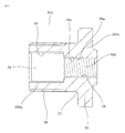
【課題】ジョイント部材の振れを抑制し、信頼性の高い回転電機を提供する。【解決手段】回転電機は、ヨーク2内の中心軸線上に回転自在に設けられた出力軸7と、出力軸7に固定された回転子8と、出力軸7の他方側の出力端部7bが圧入されるジョイント部材200とを備える。ジョイント部材200は、一方側に形成され、出力軸7の出力端部7bが圧入される圧入孔31を有する圧入部32と、他方側に形成され、出力軸7の回転トルクが伝達される被動軸と係合される係合部34とにより構成され、ジョイント部材200の圧入部32の圧入孔31に形成された溝部38、または出力軸7の出力端部7bに形成された溝部を設けている。【選択図】図1A rotating electrical machine with high reliability that suppresses vibration of a joint member is provided. An electric rotating machine includes an output shaft 7 rotatably provided on a central axis in a yoke 2, a rotor 8 fixed to the output shaft 7, and an output end 7b on the other side of the output shaft 7. And a joint member 200 to be press-fitted. The joint member 200 is formed on one side and has a press-fit portion 32 having a press-fit hole 31 into which the output end portion 7b of the output shaft 7 is press-fitted, and a driven member to which the rotational torque of the output shaft 7 is transmitted. And a groove portion 38 formed in the press-fit hole 31 of the press-fit portion 32 of the joint member 200 or a groove portion formed in the output end portion 7 b of the output shaft 7. Yes. [Selection] Figure 1
Description
この発明は、例えば車両のステアリングの操舵力を補助する電動パワーステアリング装置に用いられる回転電機に関し、回転電機の出力軸に嵌合されるジョイント部材に関するものである。 The present invention relates to a rotating electrical machine used in, for example, an electric power steering device that assists the steering force of a vehicle steering, and relates to a joint member that is fitted to an output shaft of the rotating electrical machine.
従来の回転電機におけるジョイント部材としては、例えば、特開2002−369443号公報に開示されたものがある。特開2002−369443号公報において、出力軸にはスプライン部が形成されており、焼き入れが施されている。出力軸に嵌合されるジョイント部材は出力軸と同硬度となっており、ジョイント部材には出力軸取付孔が形成されている。そして、焼き入れされた出力軸のスプライン部がジョイント部材の出力軸取付孔に噛み込みながら圧入固定されている。 As a joint member in a conventional rotating electrical machine, for example, there is one disclosed in JP-A-2002-369443. In Japanese Patent Application Laid-Open No. 2002-369443, a spline portion is formed on the output shaft, and quenching is performed. The joint member fitted to the output shaft has the same hardness as the output shaft, and an output shaft mounting hole is formed in the joint member. The spline portion of the hardened output shaft is press-fitted and fixed while being bitten into the output shaft mounting hole of the joint member.
上述した従来の回転電機は、出力軸のスプライン部をジョイント部材の出力軸取付孔に噛み込みながら圧入するようにしているので、ジョイント部材の振れが大きくなるという問題点があった。 The conventional rotating electric machine described above has a problem in that the joint member is greatly shaken because the spline portion of the output shaft is press-fitted while being engaged with the output shaft mounting hole of the joint member.
また、出力軸のスプライン部の形成のための加工や焼き入れを別途行う必要があり、工数が増加するという問題点があった。 In addition, there is a problem that man-hours increase because it is necessary to separately perform processing and quenching for forming the spline portion of the output shaft.
この発明は、上記のような課題を解決するためになされたものであり、その目的は、信頼性の高い回転電機を提供するものである。 The present invention has been made to solve the above-described problems, and an object of the present invention is to provide a highly reliable rotating electrical machine.
この発明に係わる回転電機は、ヨーク内の中心軸線上に回転自在に設けられた出力軸と、前記出力軸に固定された回転子と、前記出力軸の他方側の出力端部が圧入されるジョイント部材とを備えた回転電機であって、前記ジョイント部材は、一方側に形成され、前記出力軸の前記出力端部が圧入される圧入孔を有する圧入部と、他方側に形成され、前記出力軸の回転トルクが伝達される被動軸と係合される係合部とにより構成され、前記ジョイント部材の前記圧入部の前記圧入孔または前記出力軸の前記出力端部に形成された溝部を設けたものである。 In the rotating electrical machine according to the present invention, an output shaft rotatably provided on a central axis in the yoke, a rotor fixed to the output shaft, and an output end on the other side of the output shaft are press-fitted. A rotary electric machine including a joint member, wherein the joint member is formed on one side, a press-fit portion having a press-fit hole into which the output end portion of the output shaft is press-fitted, and the other side, A groove portion formed in the press-fitting hole of the press-fitting portion of the joint member or the output end portion of the output shaft, the engaging portion being engaged with a driven shaft to which the rotational torque of the output shaft is transmitted. It is provided.
この発明に係わる回転電機によれば、ジョイント部材の圧入部の圧入孔または出力軸の出力端部に形成された溝部を設けたことにより、出力軸の出力端部がジョイント部材の圧入部の圧入孔に信頼性を高めて圧入することができる回転電機を得ることができる。 According to the rotating electrical machine according to the present invention, by providing the press-fitting hole of the press-fitting portion of the joint member or the groove formed at the output end of the output shaft, the output end of the output shaft is press-fitted to the press-fitting portion of the joint member. A rotating electrical machine that can be press-fitted into the hole with increased reliability can be obtained.
実施の形態1.
以下、この発明の実施の形態1を図1から図3に基づいて説明するが、各図において、同一、または相当部材、部位については同一符号を付して説明する。図1はこの発明の実施の形態1に係わる回転電機を示す断面図である。図2はこの発明の実施の形態1に係わる回転電機におけるジョイント部材を示す断面図である。図3はこの発明の実施の形態1に係わる回転電機におけるジョイント部材の加工方法を示す説明図である。
Embodiment 1 FIG.
Hereinafter, Embodiment 1 of the present invention will be described with reference to FIGS. 1 to 3. In the drawings, the same or equivalent members and parts will be described with the same reference numerals. 1 is a cross-sectional view showing a rotary electric machine according to Embodiment 1 of the present invention. FIG. 2 is a cross-sectional view showing a joint member in the rotary electric machine according to Embodiment 1 of the present invention. FIG. 3 is an explanatory view showing a method of processing a joint member in the rotary electric machine according to Embodiment 1 of the present invention.
図1は、この発明の実施の形態1に係る回転電機として、電動パワーステアリング装置用のモータ100の場合を示す断面図である。回転電機であるモータ100は、有底円筒状のケースであるヨーク2と、ヨーク2の内壁面に周方向に等分間隔をおいて固定された4極の界磁永久磁石3と、ヨーク2の有底側のベアリング収納部5に収納されたリヤベアリング6により、一端部7aが回転自在に支承された回転軸である出力軸7と、出力軸7に固定された回転子であるアマチュア8と、出力軸7に固定された整流子9と、整流子9の表面にスプリング10の弾性力により当接したブラシ11と、ブラシ11を保持したブラシホルダ12と、ねじ13によりヨーク2と一体化されたハウジング14と、ハウジング14の中心部に固定され、出力軸7の他方側である出力端部7bを回転自在に支承するフロントベアリング15と、出力軸7の出力端部7bが圧入されて固定されるジョイント部材200と、ブラシ11に接続されるリード線17が貫通したグロメット18とを備えている。
FIG. 1 is a cross-sectional view showing a case of a
アマチュア8は、軸線方向に延びており周方向に間隔をおいて形成された複数のスロットを有するコア19と、スロットに導線が重巻方式で巻回されて構成された巻線20とを備えており、巻線20は整流子9に接続されている。
The amateur 8 includes a
上述した構成のモータ100では、リード線17からブラシ11を介して、整流子9に接続された巻線20に電流を供給すると、アマチュア8は界磁永久磁石3との電磁作用により、出力軸7とともに回転する。この出力軸7の出力端部7bは、ジョイント部材200の圧入孔31に圧入され、また、被動軸(図示せず)が、出力軸7の回転トルクが伝達される被動軸と係合されるジョイント部材200の係合部34に形成したスプライン部33にスプライン結合されているので、出力軸7の回転トルクは被動軸に確実に伝達され、ステアリング(図示せず)の操舵力の補助に供される。
In the
図2は、図1のジョイント部材200の断面図である。ジョイント部材200の一方側200aには、出力軸7が圧入される圧入孔31を有する圧入部32を有しており、圧入部32の圧入孔31の内周は、内径円周上に溝部38を有した丸形状(円形形状)であり、圧入部32の圧入孔31に出力軸7の出力端部7bが圧入される。
FIG. 2 is a cross-sectional view of the
また、ジョイント部材200の他方側200bには、出力軸7の回転トルクが伝達される被動軸(図示せず)とスプライン係合される係合部34を有しており、係合部34の内周は、圧入孔31よりも内径が大きいスプライン部33が形成されており、スプライン部33を介して、被動軸とスプライン結合される。
Further, the
図3は、この発明の実施の形態1におけるジョイント部材200の加工方法を示す説明図である。ジョイント部材200は、鉄等からなる金属製の母材42を、冷間鍛造加工して、一部品で形成される。すなわち、図3に示すように、ダイス40内に成形ピン(ピン部材)41を設置し、ダイス40内に配置した母材42を、成形ピン41の上方からポンチ43にて加圧することにより形成される。
FIG. 3 is an explanatory diagram showing a method of processing the
この場合、成形ピン41の上方には、圧入孔31の下穴形成のための先端部41aが設けられているとともに、成形ピン41の下方であって、その外周部には、インボリュートスプラインが形成されたスプライン部44が設けられている。なお、成形ピン41の先端部41aの外径は、スプライン部44が設けられた部分の外径よりも小径である。
In this case, a
そして、母材42を上方から成形ピン41に当接させつつ押圧することにより、母材42が軸方向に塑性変形することで、内部にスプライン部33を有する係合部34が形成されるとともに、係合部34と反対面であって、圧入部32の内周には、先端部41aによって、圧入孔31よりも小径の下穴が形成される。
Then, by pressing the
さらに、母材42が塑性変形することで、圧入部32の外周には、径方向外側に延出する延出部(つば)35が形成される。
Furthermore, the
次に、この下穴に対してスプライン部33を基準とした切削加工が行われることにより、内径円周上に溝部38を有した丸形状の圧入孔31が形成される。これにより、圧入部32の圧入孔31、スプライン部33を有する係合部34は良好な精度でジョイント部材200として形成される。
Next, by cutting the prepared hole using the
このとき、延出部35の角部37はR形状に形成されている(図2参照)。なお、図2では、延出部35の角部37がR形状に形成されるようにダイス40を構成した場合について示したが、この場合に限定されるものではなく、所定の傾斜角度(例えば、30度)のテーパ形状に形成されるようにダイス40を構成してもよい。
At this time, the
また、ジョイント部材200の圧入部32の外周には、径方向外側に延出する延出部35が、ジョイント部材200とともに冷間鍛造加工にて一体形成されており、その結果、圧入部32の肉厚が厚くなることから、出力軸7が圧入部32の圧入孔31に圧入される際に、圧入部32にかかる引張応力に対する耐性が向上する。それゆえ、圧入時の割れの発生を抑制することができ、かつ、出力軸7とジョイント部材200との固着力を十分に確保することができる。
Further, on the outer periphery of the press-
また、冷間鍛造加工により、係合部34および延出部35が形成されるとともに、係合部34の外周にわたって、周方向に等間隔で複数の溝36が、係合部34および圧入部32とともに一体に設けられる。
In addition, the cold forging process forms the
なお、この発明の実施の形態1では、係合部34の外周にわたって溝36が形成された場合について示したが、この場合に限らず、ジョイント部材200の外周であって、被動軸側端部から出力軸7側に向けて溝36が形成されるとともに、この溝36の長さが係合部34の軸方向長さよりも長く、ジョイント部材200の軸方向長さよりも短くなるようにすればよく、例えば、ジョイント部材200の外周であって、係合部34の被動軸側端部から圧入部32の一部にわたって溝36が形成される場合であってもよい。溝36が、被動軸側端部から出力軸7側に向けて形成されるとともに、この溝36の長さが係合部34の軸方向長さよりも長いことから、少なくとも係合部34の外周全体にわたって溝36
が形成される。
In the first embodiment of the present invention, the case where the
Is formed.
この発明の実施の形態1では、このように構成されているので、筒状のヨーク2と、このヨーク2内の中心軸線上に回転自在に設けられた出力軸7と、この出力軸7に固定されたアマチュア8と、一方側に出力軸7の出力端部7bが圧入される圧入孔31を有する圧入部32を有し、他方側に出力軸7の回転トルクが伝達される被動軸とスプライン係合されるスプライン部33を有する係合部34を有するとともに、金属製の母材42を冷間鍛造加工して形成されたジョイント部材200とを備え、圧入部32の内周に形成された圧入孔31に溝部38を有しており、出力軸7の出力端部7bが、圧入部32の内周に形成された圧入孔31に圧入されるので、圧入時にかじり等によって生じる圧入削りカスが溝部38に逃げることによって、圧入が妨げられることなく、圧入不良を抑制することができる。
Since the first embodiment of the present invention is configured as described above, the
また、かじり等で生じる削りカスが溝部38に逃げることによって、圧入完了時のジョイント部材200が出力軸7の出力端部7bに対して、曲がることなく圧入されるため、出力軸7の軸線基準に対するジョイント部材200の振れを抑制することができる。
Further, since the shaving residue generated by galling or the like escapes into the
さらに、溝部38は複数設けているので、かじり等で生じる削りカスが複数の溝部38に逃げることができるので、圧入に対しての安定性がさらに向上する。
このように、信頼性の高い回転電機を得ることができる。
In addition, since a plurality of
Thus, a highly reliable rotating electrical machine can be obtained.
実施の形態2.
この発明の実施の形態2を図4に基づいて説明するが、各図において、同一、または相当部材、部位については同一符号を付して説明する。図4はこの発明の実施の形態1に係わる回転電機における出力軸の先端部を示す拡大図である。
The second embodiment of the present invention will be described with reference to FIG. 4. In the drawings, the same or corresponding members and parts will be described with the same reference numerals. FIG. 4 is an enlarged view showing the tip end portion of the output shaft in the rotary electric machine according to Embodiment 1 of the present invention.
上述した実施の形態1においては、圧入部32の圧入孔31の内径円周上に溝部38を有する場合について示したが、代わりに、図4に示すように、圧入部32の圧入孔31ではなく、出力軸7の出力端部7bの外径円周上に同様の溝部7cを有してもよい。
In the first embodiment described above, the case where the
図4は、出力軸7の出力端部7bの拡大図である。出力軸7の出力端部7bは外径円周上に複数の溝部7cを有した丸形状部7d(円形形状)であり、圧入部32の圧入孔31へ圧入される。なお、出力軸7の出力端部7bの外径円周上に同様の溝部7cを有する場合について示したが、図2に示すように圧入部32の圧入孔31に内径円周上に溝部38を有していてもよい。
FIG. 4 is an enlarged view of the
なお、この発明の実施の形態2に係る溝部以外の構成は、実施の形態1と同じであるので、その詳細説明は省略する。
In addition, since structures other than the groove part which concerns on
この発明の実施の形態2では、このように構成されているので、筒状のヨーク2と、このヨーク2内の中心軸線上に回転自在に設けられた出力軸7と、この出力軸7に固定されたアマチュア8と、一方側200aに出力軸7が圧入される圧入孔31を有する圧入部32を有し、他方側200bに出力軸7の回転トルクが伝達される被動軸とスプライン係合されるスプライン部33を有する係合部34を有するとともに、金属製の母材42を冷間鍛造加工して形成されたジョイント部材200とを備え、出力軸7の出力端部7bに溝部7cを有しており、出力軸7の出力端部7bが、圧入部32の内周に形成された圧入孔31に圧入されるので、圧入時にかじり等によって生じる圧入削りカスが出力軸7の出力端部7bの溝部7cに逃げることによって、圧入が妨げられることなく、圧入不良を抑制することができる。
Since the second embodiment of the present invention is configured as described above, the
また、かじり等で生じる削りカスが出力軸7の出力端部7bの溝部7cに逃げることによって、圧入完了時のジョイント部材200が出力軸7の出力端部7bに対して、曲がることなく圧入されるため、出力軸7の軸線基準に対するジョイント部材200の振れを抑制することができる。そのうえ、出力軸7の出力端部7bの溝部7cを複数有することにより、圧入に対しての安定性がさらに向上する。
このように、信頼性の高い回転電機を得ることができる。
Further, the shavings generated by galling or the like escape into the
Thus, a highly reliable rotating electrical machine can be obtained.
実施の形態3.
この発明の実施の形態3を図5に基づいて説明するが、図において、同一、または相当部材、部位については同一符号を付して説明する。図5はこの発明の実施の形態3に係わる回転電機におけるジョイント部材を示す断面図である。
A third embodiment of the present invention will be described with reference to FIG. 5. In the figure, the same or equivalent members and parts will be described with the same reference numerals. 5 is a cross-sectional view showing a joint member in a rotary electric machine according to
図5は、この発明の実施の形態3におけるジョイント部材300の断面図である。ジョイント部材300の一方側300aには、出力軸7の出力端部7bが圧入される圧入孔31を有する圧入部32aを有しており、圧入部32aの圧入孔31の内周は、内径円周上に螺旋形状の溝部38aを有した丸形状部39(円形形状)であり、出力軸7の出力端部7bが圧入部32aの圧入孔31に圧入される。
FIG. 5 is a cross-sectional view of
なお、圧入部32aの圧入孔31の内径円周上に螺旋形状の溝部38aを有する場合について示したが、上述した実施の形態2と同様に、代わりに、圧入部32aの圧入孔31ではなく、出力軸7の出力端部7bの外径円周上に同様の螺旋形状の溝部としてもよい。
In addition, although it showed about the case where it has the spiral-shaped
また、この発明の実施の形態3におけるジョイント部材300において、図5に示したジョイント部材300の圧入部32a以外の構成は、図2に示すジョイント部材200と同じであるので、その詳細説明は省略する。
Further, in the
この発明の実施の形態3では、このように構成されているので、筒状のヨーク2と、このヨーク2内の中心軸線上に回転自在に設けられた出力軸7と、この出力軸7に固定されたアマチュア8と、一方側300aに出力軸7の出力端部7bが圧入される圧入孔31を有する圧入部32aを有し、他方側300bに出力軸7の回転トルクが伝達される被動軸とスプライン係合されるスプライン部33を有する係合部34を有するとともに、金属製の母材42を冷間鍛造加工して形成されたジョイント部材300とを備え、圧入部32aの内周に形成された圧入孔31に螺旋形状の溝部38aを有しており、出力軸7の出力端部7bが、圧入部32aの内周に形成された圧入孔31に圧入されるので、圧入時にかじり等によって生じる圧入削りカスが螺旋形状の溝部38aに逃げることによって、圧入が妨げられることなく、圧入不良を抑制することができる。
Since the third embodiment of the present invention is configured in this manner, the
また、かじり等で生じる削りカスが螺旋形状の溝部38aに逃げることによって、圧入完了時のジョイント部材300が出力軸7の出力端部7bに対して、曲がることなく圧入されるため、出力軸7の軸線基準に対するジョイント部材300の振れを抑制することができる。さらに、螺旋形状の溝部38aを設けることにより、出力軸7とジョイント部材300との回転方向の固着力低減を防止することができる。
このように、信頼性の高い回転電機を得ることができる。
Further, since the shavings generated by galling or the like escape into the
Thus, a highly reliable rotating electrical machine can be obtained.
実施の形態4.
この発明の実施の形態4を図6に基づいて説明するが、図において、同一、または相当部材、部位については同一符号を付して説明する。図6はこの発明の実施の形態4に係わる回転電機におけるジョイント部材を示す断面図である。
Embodiment 4 FIG.
Embodiment 4 of the present invention will be described with reference to FIG. 6. In the figure, the same or equivalent members and parts will be described with the same reference numerals. 6 is a cross-sectional view showing a joint member in a rotary electric machine according to Embodiment 4 of the present invention.
図6は、この発明の実施の形態4におけるジョイント部材400の断面図である。ジョイント部材400の一方側400aには、出力軸7の出力端部7bが圧入される圧入孔31を有する圧入部32bを有しており、圧入部32bの圧入孔31の内周は、内径円周上に螺旋形状の溝部38bを有し、且つ、一部凹凸部が形成されていない丸形状部39b(円形形状)を例えば圧入入口側に有し、出力軸7の出力端部7bが圧入部32bの圧入孔31に圧入される。
FIG. 6 is a cross-sectional view of
なお、圧入部32bの圧入孔31の内径円周上に螺旋形状の溝部38bを有する場合について示したが、出力軸7の出力端部7bの外径円周上に同様の螺旋形状の溝部を有していてもよい。
In addition, although it showed about the case where it has the spiral-shaped
また、この発明の実施の形態4におけるジョイント部材400において、図6に示したジョイント部材400の圧入部32b以外の構成は、図2に示すジョイント部材200と同じであるので、その詳細説明は省略する。
Further, in the
この発明の実施の形態4では、このように構成されているので、筒状のヨーク2と、このヨーク2内の中心軸上に回転自在に設けられた出力軸7と、この出力軸7に固定されたアマチュア8と、一方側400aに出力軸7の出力端部7bが圧入される圧入孔31を有する圧入部32bを有し、他方側400bに出力軸7の回転トルクが伝達される被動軸とスプライン係合されるスプライン部33を有する係合部34を有するとともに、金属製の母材42を冷間鍛造加工して形成されたジョイント部材400とを備え、圧入部32aの内周に形成された圧入孔31に螺旋形状の溝部38bを有しており、出力軸7の出力端部7bが、圧入部32aの内周に形成された圧入孔31に圧入されるので、圧入時にかじり等によって生じる圧入削りカスが螺旋形状の溝部38bに逃げることによって、圧入が妨げられることなく、圧入不良を抑制することができる。
Since the fourth embodiment of the present invention is configured as described above, the
また、かじり等で生じる削りカスが螺旋形状の溝部38bに逃げることによって、圧入完了時のジョイント部材400が出力軸7の出力端部7bに対して、曲がることなく圧入されるため、出力軸7の軸線基準に対するジョイント部材400の振れを抑制することができる。さらに、螺旋形状の溝部38bを設けることにより、出力軸7とジョイント部材400との回転方向の固着力低減を防止することができる。
このように、信頼性の高い回転電機を得ることができる。
Further, since the shaving residue generated by galling or the like escapes to the
Thus, a highly reliable rotating electrical machine can be obtained.
また、ジョイント部材400の圧入部32bには、一部凹凸部が形成されていない丸形状部40を有するため、異物侵入を丸形状部39bにより防ぐことができる。そのうえ、圧入部32bの圧入入口側に丸形状部39b(円形形状)を有するため、圧入に対しての安定性がさらに向上する。
Further, since the press-
なお、この発明は、その発明の範囲内において、各実施の形態を自由に組み合わせたり、各実施の形態を適宜、変形、省略することが可能である。 It should be noted that within the scope of the present invention, the embodiments can be freely combined, or the embodiments can be appropriately modified or omitted.
この発明は、信頼性の高い回転電機の実現に好適である。 The present invention is suitable for realizing a highly reliable rotating electrical machine.
2 ヨーク、3 界磁永久磁石、5 ベアリング収納部、6 リヤベアリング、7 出力軸、7b 出力端部、7c 溝、7d 丸形状部、8 アマチュア(回転子)、9 整流子、10 スプリング、11 ブラシ、12 ブラシホルダ、13 ねじ、14 ハウジング、15 フロントベアリング、17 リード線、18 グロメット、19 コア、20 巻線、31 圧入孔、32 圧入部、32a 圧入部、32b 圧入部、33 スプライン部、34 係合部、38 溝部、38a 螺旋形状の溝部、38b 螺旋形状の
溝部、39 丸形状部、39a 丸形状部、39b 丸形状部、40 ダイス、41 成形ピン(ピン部材)、41a 先端部、42 母材、43 ポンチ、44 スプライン部、100 モータ(回転電機)、200 ジョイント部材、200a 一方側、200b 他方側、300 ジョイント部材、300a 一方側、300b 他方側、400 ジョイント部材、400a 一方側、400b 他方側
2 yoke, 3 field permanent magnet, 5 bearing housing, 6 rear bearing, 7 output shaft, 7b output end, 7c groove, 7d round shape, 8 amateur (rotor), 9 commutator, 10 spring, 11 Brush, 12 Brush holder, 13 Screw, 14 Housing, 15 Front bearing, 17 Lead wire, 18 Grommet, 19 Core, 20 Winding, 31 Press-in hole, 32 Press-in part, 32a Press-in part, 32b Press-in part, 33 Spline part, 34 engaging portion, 38 groove portion, 38a spiral groove portion, 38b spiral groove portion, 39 round shape portion, 39a round shape portion, 39b round shape portion, 40 dies, 41 molding pin (pin member), 41a tip portion, 42 Base material, 43 punch, 44 spline part, 100 motor (rotary electric machine), 200 joint member, 200a one side, 200b etc. Side, 300 joint member, 300a on one side, 300b the other side, 400 joint member, 400a on one side, 400b other side
この発明に係わる回転電機は、ヨーク内の中心軸線上に回転自在に設けられた出力軸と、前記出力軸に固定された回転子と、前記出力軸の他方側の出力端部が圧入されるジョイント部材とを備えた回転電機であって、前記ジョイント部材は、一方側に形成され、前記出力軸の前記出力端部が圧入される圧入孔を有する圧入部と、他方側に形成され、前記出力軸の回転トルクが伝達される被動軸と係合される係合部とにより構成され、前記ジョイント部材の前記圧入部の前記圧入孔または前記出力軸の前記出力端部に形成された周方向の溝部を設けたものである。 In the rotating electrical machine according to the present invention, an output shaft rotatably provided on a central axis in the yoke, a rotor fixed to the output shaft, and an output end on the other side of the output shaft are press-fitted. A rotary electric machine including a joint member, wherein the joint member is formed on one side, a press-fit portion having a press-fit hole into which the output end portion of the output shaft is press-fitted, and the other side, The circumferential direction formed in the press-fitting hole of the press-fitting part of the joint member or the output end part of the output shaft, the engaging part being engaged with a driven shaft to which the rotational torque of the output shaft is transmitted it is provided with a groove portion.
Claims (5)
The rotating electrical machine according to claim 4, wherein the round shape portion is provided at a press-fit inlet of the press-fit hole of the press-fit portion of the joint member.
Priority Applications (1)
| Application Number | Priority Date | Filing Date | Title |
|---|---|---|---|
| JP2015100792A JP2016220332A (en) | 2015-05-18 | 2015-05-18 | Rotating electric machine |
Applications Claiming Priority (1)
| Application Number | Priority Date | Filing Date | Title |
|---|---|---|---|
| JP2015100792A JP2016220332A (en) | 2015-05-18 | 2015-05-18 | Rotating electric machine |
Publications (1)
| Publication Number | Publication Date |
|---|---|
| JP2016220332A true JP2016220332A (en) | 2016-12-22 |
Family
ID=57581859
Family Applications (1)
| Application Number | Title | Priority Date | Filing Date |
|---|---|---|---|
| JP2015100792A Pending JP2016220332A (en) | 2015-05-18 | 2015-05-18 | Rotating electric machine |
Country Status (1)
| Country | Link |
|---|---|
| JP (1) | JP2016220332A (en) |
Cited By (1)
| Publication number | Priority date | Publication date | Assignee | Title |
|---|---|---|---|---|
| JP2020195251A (en) * | 2019-05-30 | 2020-12-03 | 株式会社デンソー | motor |
Citations (10)
| Publication number | Priority date | Publication date | Assignee | Title |
|---|---|---|---|---|
| JPS57155963U (en) * | 1981-03-25 | 1982-09-30 | ||
| JPS62107654A (en) * | 1985-11-01 | 1987-05-19 | Nippon Denso Co Ltd | Generator with rotary machine |
| JPS63129715U (en) * | 1987-02-18 | 1988-08-24 | ||
| JPH01210182A (en) * | 1988-02-17 | 1989-08-23 | Hitachi Metals Ltd | Press-in joining method for cast parts |
| JPH03223513A (en) * | 1990-01-26 | 1991-10-02 | Kinugawa Rubber Ind Co Ltd | Propeller shaft for vehicle |
| JPH07259838A (en) * | 1994-03-16 | 1995-10-09 | Mitsubishi Materials Corp | Crankshaft manufacturing method |
| JP2001008402A (en) * | 1999-06-16 | 2001-01-12 | Mitsubishi Electric Corp | motor |
| JP2002369443A (en) * | 2001-06-01 | 2002-12-20 | Mitsuba Corp | Jointing member for motor, motor for electric power steering and electric power steering apparatus |
| JP2011091969A (en) * | 2009-10-26 | 2011-05-06 | Nippon Densan Corp | Motor, disk drive, method for manufacturing rotor yoke, and method for manufacturing motor |
| JP2013009519A (en) * | 2011-06-24 | 2013-01-10 | Mitsubishi Electric Corp | Rotary electric machine |
-
2015
- 2015-05-18 JP JP2015100792A patent/JP2016220332A/en active Pending
Patent Citations (10)
| Publication number | Priority date | Publication date | Assignee | Title |
|---|---|---|---|---|
| JPS57155963U (en) * | 1981-03-25 | 1982-09-30 | ||
| JPS62107654A (en) * | 1985-11-01 | 1987-05-19 | Nippon Denso Co Ltd | Generator with rotary machine |
| JPS63129715U (en) * | 1987-02-18 | 1988-08-24 | ||
| JPH01210182A (en) * | 1988-02-17 | 1989-08-23 | Hitachi Metals Ltd | Press-in joining method for cast parts |
| JPH03223513A (en) * | 1990-01-26 | 1991-10-02 | Kinugawa Rubber Ind Co Ltd | Propeller shaft for vehicle |
| JPH07259838A (en) * | 1994-03-16 | 1995-10-09 | Mitsubishi Materials Corp | Crankshaft manufacturing method |
| JP2001008402A (en) * | 1999-06-16 | 2001-01-12 | Mitsubishi Electric Corp | motor |
| JP2002369443A (en) * | 2001-06-01 | 2002-12-20 | Mitsuba Corp | Jointing member for motor, motor for electric power steering and electric power steering apparatus |
| JP2011091969A (en) * | 2009-10-26 | 2011-05-06 | Nippon Densan Corp | Motor, disk drive, method for manufacturing rotor yoke, and method for manufacturing motor |
| JP2013009519A (en) * | 2011-06-24 | 2013-01-10 | Mitsubishi Electric Corp | Rotary electric machine |
Cited By (1)
| Publication number | Priority date | Publication date | Assignee | Title |
|---|---|---|---|---|
| JP2020195251A (en) * | 2019-05-30 | 2020-12-03 | 株式会社デンソー | motor |
Similar Documents
| Publication | Publication Date | Title |
|---|---|---|
| CN105391211B (en) | The rotor of rotating electric machine | |
| US4339873A (en) | Method of making rotor of rotary machines | |
| CN105981265A (en) | Rotor, manufacturing method of rotor, and rotating electrical machine having rotor | |
| JP3958732B2 (en) | Rotating electric machine and manufacturing method thereof | |
| EP1796244A2 (en) | Rotating electrical machine for alternator and method of manufacturing rotor core used in the same | |
| JPWO2006132171A1 (en) | Rotating electrical machine armature and manufacturing method thereof | |
| JP2016220332A (en) | Rotating electric machine | |
| JP5111563B2 (en) | Rotating electric machine | |
| JP5445523B2 (en) | Rotating electric machine | |
| JP6413547B2 (en) | Manufacturing method of fixed structure, manufacturing method of rotating body, rotating body, and motor | |
| JP2016174512A (en) | Rotating electric machine and method of manufacturing rotating electric machine | |
| CN108603538A (en) | The assemble method and universal-joint-pin type universal connector of universal-joint-pin type universal connector | |
| WO2020255730A1 (en) | Start-up generator and method for manufacturing start-up generator | |
| JP5067416B2 (en) | Rotating electric machine | |
| JP2003153483A (en) | Motor bracket mounting structure | |
| JP5129723B2 (en) | Electric motor | |
| JP4746910B2 (en) | Electric actuator | |
| JP2001008402A (en) | motor | |
| JP2023036351A (en) | Rotary electric machine | |
| JPH1066287A (en) | Magnet generator rotor | |
| JP6828308B2 (en) | How to manufacture rotors and motors | |
| JP2017055470A (en) | Rotor shaft | |
| CN112217315A (en) | Welding stepping motor | |
| JP2008182814A (en) | Housing for rotating electric machine and method for manufacturing the same | |
| US20250364866A1 (en) | Motor device |
Legal Events
| Date | Code | Title | Description |
|---|---|---|---|
| A131 | Notification of reasons for refusal |
Free format text: JAPANESE INTERMEDIATE CODE: A131 Effective date: 20160913 |
|
| A521 | Written amendment |
Free format text: JAPANESE INTERMEDIATE CODE: A523 Effective date: 20161017 |
|
| A02 | Decision of refusal |
Free format text: JAPANESE INTERMEDIATE CODE: A02 Effective date: 20170314 |