JP2016508596A - Drying equipment - Google Patents
Drying equipment Download PDFInfo
- Publication number
- JP2016508596A JP2016508596A JP2015559553A JP2015559553A JP2016508596A JP 2016508596 A JP2016508596 A JP 2016508596A JP 2015559553 A JP2015559553 A JP 2015559553A JP 2015559553 A JP2015559553 A JP 2015559553A JP 2016508596 A JP2016508596 A JP 2016508596A
- Authority
- JP
- Japan
- Prior art keywords
- flow
- gas
- drying
- drying apparatus
- flow rate
- Prior art date
- Legal status (The legal status is an assumption and is not a legal conclusion. Google has not performed a legal analysis and makes no representation as to the accuracy of the status listed.)
- Pending
Links
- JSIYGGNTVMFDHJ-UHFFFAOYSA-N C1C2=CCCCC12 Chemical compound C1C2=CCCCC12 JSIYGGNTVMFDHJ-UHFFFAOYSA-N 0.000 description 1
Images



Classifications
-
- A—HUMAN NECESSITIES
- A24—TOBACCO; CIGARS; CIGARETTES; SIMULATED SMOKING DEVICES; SMOKERS' REQUISITES
- A24B—MANUFACTURE OR PREPARATION OF TOBACCO FOR SMOKING OR CHEWING; TOBACCO; SNUFF
- A24B3/00—Preparing tobacco in the factory
- A24B3/04—Humidifying or drying tobacco bunches or cut tobacco
-
- F—MECHANICAL ENGINEERING; LIGHTING; HEATING; WEAPONS; BLASTING
- F26—DRYING
- F26B—DRYING SOLID MATERIALS OR OBJECTS BY REMOVING LIQUID THEREFROM
- F26B17/00—Machines or apparatus for drying materials in loose, plastic, or fluidised form, e.g. granules, staple fibres, with progressive movement
- F26B17/10—Machines or apparatus for drying materials in loose, plastic, or fluidised form, e.g. granules, staple fibres, with progressive movement with movement performed by fluid currents, e.g. issuing from a nozzle, e.g. pneumatic, flash, vortex or entrainment dryers
- F26B17/107—Machines or apparatus for drying materials in loose, plastic, or fluidised form, e.g. granules, staple fibres, with progressive movement with movement performed by fluid currents, e.g. issuing from a nozzle, e.g. pneumatic, flash, vortex or entrainment dryers pneumatically inducing within the drying enclosure a curved flow path, e.g. circular, spiral, helical; Cyclone or Vortex dryers
-
- F—MECHANICAL ENGINEERING; LIGHTING; HEATING; WEAPONS; BLASTING
- F26—DRYING
- F26B—DRYING SOLID MATERIALS OR OBJECTS BY REMOVING LIQUID THEREFROM
- F26B17/00—Machines or apparatus for drying materials in loose, plastic, or fluidised form, e.g. granules, staple fibres, with progressive movement
- F26B17/10—Machines or apparatus for drying materials in loose, plastic, or fluidised form, e.g. granules, staple fibres, with progressive movement with movement performed by fluid currents, e.g. issuing from a nozzle, e.g. pneumatic, flash, vortex or entrainment dryers
- F26B17/101—Machines or apparatus for drying materials in loose, plastic, or fluidised form, e.g. granules, staple fibres, with progressive movement with movement performed by fluid currents, e.g. issuing from a nozzle, e.g. pneumatic, flash, vortex or entrainment dryers the drying enclosure having the shape of one or a plurality of shafts or ducts, e.g. with substantially straight and vertical axis
-
- F—MECHANICAL ENGINEERING; LIGHTING; HEATING; WEAPONS; BLASTING
- F26—DRYING
- F26B—DRYING SOLID MATERIALS OR OBJECTS BY REMOVING LIQUID THEREFROM
- F26B21/00—Arrangements for supplying or controlling air or other gases for drying solid materials or objects
- F26B21/30—Controlling, e.g. regulating, parameters of gas supply
- F26B21/37—Velocity of flow; Quantity of flow
-
- F—MECHANICAL ENGINEERING; LIGHTING; HEATING; WEAPONS; BLASTING
- F26—DRYING
- F26B—DRYING SOLID MATERIALS OR OBJECTS BY REMOVING LIQUID THEREFROM
- F26B3/00—Drying solid materials or objects by processes involving the application of heat
- F26B3/02—Drying solid materials or objects by processes involving the application of heat by convection, i.e. heat being conveyed from a heat source to the materials or objects to be dried by a gas or vapour, e.g. air
- F26B3/10—Drying solid materials or objects by processes involving the application of heat by convection, i.e. heat being conveyed from a heat source to the materials or objects to be dried by a gas or vapour, e.g. air the gas or vapour carrying the materials or objects to be dried with it
-
- F—MECHANICAL ENGINEERING; LIGHTING; HEATING; WEAPONS; BLASTING
- F26—DRYING
- F26B—DRYING SOLID MATERIALS OR OBJECTS BY REMOVING LIQUID THEREFROM
- F26B2200/00—Drying processes and machines for solid materials characterised by the specific requirements of the drying goods
- F26B2200/22—Tobacco leaves
-
- F—MECHANICAL ENGINEERING; LIGHTING; HEATING; WEAPONS; BLASTING
- F26—DRYING
- F26B—DRYING SOLID MATERIALS OR OBJECTS BY REMOVING LIQUID THEREFROM
- F26B23/00—Heating arrangements
- F26B23/001—Heating arrangements using waste heat
- F26B23/002—Heating arrangements using waste heat recovered from dryer exhaust gases
- F26B23/004—Heating arrangements using waste heat recovered from dryer exhaust gases by compressing and condensing vapour in exhaust gases, i.e. using an open cycle heat pump system
-
- Y—GENERAL TAGGING OF NEW TECHNOLOGICAL DEVELOPMENTS; GENERAL TAGGING OF CROSS-SECTIONAL TECHNOLOGIES SPANNING OVER SEVERAL SECTIONS OF THE IPC; TECHNICAL SUBJECTS COVERED BY FORMER USPC CROSS-REFERENCE ART COLLECTIONS [XRACs] AND DIGESTS
- Y02—TECHNOLOGIES OR APPLICATIONS FOR MITIGATION OR ADAPTATION AGAINST CLIMATE CHANGE
- Y02P—CLIMATE CHANGE MITIGATION TECHNOLOGIES IN THE PRODUCTION OR PROCESSING OF GOODS
- Y02P70/00—Climate change mitigation technologies in the production process for final industrial or consumer products
- Y02P70/10—Greenhouse gas [GHG] capture, material saving, heat recovery or other energy efficient measures, e.g. motor control, characterised by manufacturing processes, e.g. for rolling metal or metal working
Landscapes
- Engineering & Computer Science (AREA)
- Mechanical Engineering (AREA)
- General Engineering & Computer Science (AREA)
- Life Sciences & Earth Sciences (AREA)
- Microbiology (AREA)
- Drying Of Solid Materials (AREA)
Abstract
繊維性材料(又は粒状材料)を乾燥するための乾燥装置が開示されている。当該乾燥装置は、第1のガス流および繊維性材料を加熱するように構成された加熱器を備え、第1のガス流は吸気口で乾燥装置に流入するように構成され、前記ガス流は蒸気を含む。第1のガス流から繊維性材料を分離して第2のガス流を形成するための分離器が設けられ、ファンおよびダクトが、第2のガス流をプロセス加熱器と蒸気注入装置へと再循環させるように構成されている。流量変更装置は、第1のガス流におけるガス流れを変更して、ガス流とタバコ製品の間の熱伝達および物質移動の増大により乾燥機能を向上(改善)するように構成されている。【選択図】図2A drying apparatus for drying fibrous material (or granular material) is disclosed. The drying apparatus includes a heater configured to heat the first gas stream and the fibrous material, the first gas stream configured to flow into the drying apparatus at an inlet, wherein the gas stream is Contains steam. A separator is provided for separating the fibrous material from the first gas stream to form a second gas stream, and a fan and duct recirculate the second gas stream to the process heater and the steam injector. It is configured to circulate. The flow rate changing device is configured to change the gas flow in the first gas flow to improve (improve) the drying function by increasing heat transfer and mass transfer between the gas flow and the tobacco product. [Selection] Figure 2
Description
本発明は、繊維性又は粒状の材料を乾燥するための乾燥装置および方法に関し、とりわけ、たばこ葉またはたばこ葉の一部といった繊維性材料を乾燥する乾燥装置および方法に関するが、それに限定されない。 The present invention relates to a drying apparatus and method for drying fibrous or granular materials, and more particularly, but not limited to, a drying apparatus and method for drying fibrous materials such as tobacco leaves or portions of tobacco leaves.
たばこ葉は、一次たばこ加工で紙巻たばこ製造用に加工処理される。紙巻たばこ製造に適したたばこ粒子(小片)を提供するために、たばこ葉の積層部分が圧縮され、次いで、裁刻機で裁刻される。一般的にたばこ材料の取扱特性および充填特性を改善するために、繊維性のたばこ材料から水分が除去される。 Tobacco leaves are processed for the manufacture of cigarettes by primary tobacco processing. To provide tobacco particles (small pieces) suitable for cigarette manufacture, the tobacco leaf stack is compressed and then cut with a cutter. In general, moisture is removed from the fibrous tobacco material to improve the handling and filling properties of the tobacco material.
たばこ産業界では、紙巻たばこ製造および包装に適したレベルまで紙巻たばこ充填材の含水量を減少させるために、フラッシュ乾燥機(flash dryer)としても知られる気流運搬乾燥機(pneumatic conveying dryer)を使用することが知られている。このような乾燥機の一般原則は、たばこ製品が、高温ガスの流れによって通路に沿って運搬されるというものである。ガスの流れは、通路内でたばこ製品が分散および乾燥される環境をもたらす。次いでたばこ製品は、何らかの手段でガス流から分離される。製品乾燥は、ガス流とたばこ製品との間の熱伝達および物質移動により行われる。運搬用ガスとして、過熱流、空気、空気と二酸化炭素の混合物、または他の燃焼成分を伴う空気を使用することが知られている。 The tobacco industry uses a pneumatic conveying dryer, also known as a flash dryer, to reduce the moisture content of the cigarette filler to a level suitable for cigarette manufacture and packaging It is known to do. The general principle of such dryers is that tobacco products are transported along a passage by a flow of hot gas. The gas flow provides an environment in which the tobacco product is dispersed and dried in the passage. The tobacco product is then separated from the gas stream by any means. Product drying takes place by heat and mass transfer between the gas stream and the tobacco product. It is known to use superheated flow, air, a mixture of air and carbon dioxide, or air with other combustion components as the carrier gas.
たばこは、紙巻たばこのもっとも高価な構成要素であることから、製造者には、既定の重量のタバコから製造されうる紙巻たばこの数を最大化する方法でたばこを加工処理する、という強い動機がある。裁刻たばこ製品をより低い密度で生成することは、出発製品の既定の重量からより多くの生産量(収量)をもたらす。フラッシュ乾燥機としても知られる気流運搬乾燥機、および、乾燥媒体としての過熱流による本乾燥は、他の乾燥方法を用いた結果(場合)よりも、より低密度の裁刻タバコによる収量改善をもたらす。 Because cigarettes are the most expensive component of cigarettes, manufacturers have a strong motivation to process tobacco in a way that maximizes the number of cigarettes that can be produced from a given weight of tobacco. is there. Producing chopped tobacco products at a lower density results in more output (yield) from the default weight of the starting product. Air-drying dryers, also known as flash dryers, and main drying with superheated flow as a drying medium, improve yields with lower-density chopped tobacco than results (if any) using other drying methods. Bring.
図1は、従来の乾燥装置100(例えば気流運搬乾燥機)を示している。この乾燥装置100は、プロセス加熱器10と、製品供給装置1と、材料の排出および解放を制御する装置を備え、本例では当該解放装置は回転エアロック2を備え、更に(乾燥装置100は)乾燥ダクト3、分離器および別の回転エアロック、並びに排出装置5を備える。典型的には、分離器はサイクロン式分離器4である。格納されたたばこ製品は乾燥装置を通り、供給装置1によって含水(又は湿潤)たばこ製品の流れが生成される。次いで、含水たばこ製品は回転エアロック2を通過し、製品はダクト3へと分散し、ガスと固体の混合物が、ダクト3に沿って、高温ガスの運搬流によってサイクロン式分離器4へと運搬される。高温ガスはたばこ製品に熱を与え、たばこの水分の一部を蒸発させる。サイクロン式分離器4は、たばこ製品の乾燥固体(乾燥固形分)をガス流から分離する。乾燥されたたばこ製品は、エアロック5を通じて排出され、次いで、必要に応じて、紙巻たばこ製造プロセスの次の段階へと運搬される。
FIG. 1 shows a conventional drying apparatus 100 (for example, an air current dryer). The
図1に示される従来の乾燥装置は更に、運搬ガス流を捕捉し再循環させる構成要素を備える。乾燥装置は、ファン6、排気口7、収集ダクト8および蒸気注入装置をさらに備える。サイクロン式分離器4を出たガス流は、プロセス加熱器10または他の熱源(熱交換器)に向けて再循環させるためにファン6へ搬送され、そして再び乾燥ダクト3へ搬送される。蒸気は、適切な制御バルブ9および流量計測システムを介して本システムに注入される。ファン6は、ダクト8に沿ってガス流を運搬するのに十分な圧力を生成するように動作する。余剰ガス(返流したガスの一部)は排気口7で排出または放出され、システムの物質収支を維持する。余剰ガスは、エアロックや蒸気注入における不可避的な空気の内部漏出、および、本来水分を含むたばこ製品からの水分蒸発に起因する。図1に図示される例では、余剰ガスは大気中に排出されるよう示されているが、ガスは放出前に処理または浄化され得る。例は、蒸気放出からあらゆる不純物、臭気、汚染物を除去するために、凝結(凝縮)または、例えば化学洗浄などの洗浄を含む。
The conventional drying apparatus shown in FIG. 1 further comprises components that capture and recirculate the carrier gas stream. The drying device further includes a
気流運搬乾燥機による密度低下および生産量向上(収量改善)は、熱が乾燥ガスから製品へと伝導される速度の関数であるところの乾燥プロセスの速度(迅速性)に起因する。高速の熱伝達は、穏やかな熱伝達により発生される蒸気圧と比較して、たばこの細胞マトリックス内に、より高い蒸気圧を生じさせるであろう。内部蒸気圧が周囲の蒸気圧よりも高い場合、細胞マトリックスは膨張しやすく、結果として、乾燥プロセスの最中および乾燥プロセス後に、たばこ製品の密度低下をもたらす。乾燥ガスとたばこ製品の間の熱伝達は、乾燥ガスの多数の要因、とりわけ熱力学特性によって決定される。というのも、熱力学特性は、ガスが乾燥機を通って運搬される時、製品の各粒子表面を包囲するガスの境界層の熱伝達特性に影響を及ぼすためである。 Density reduction and production increase (yield improvement) with an air-borne dryer is due to the speed (rapidity) of the drying process as a function of the rate at which heat is transferred from the drying gas to the product. High-speed heat transfer will produce higher vapor pressure in the tobacco cell matrix compared to vapor pressure generated by gentle heat transfer. When the internal vapor pressure is higher than the ambient vapor pressure, the cell matrix tends to swell, resulting in a reduced density of tobacco products during and after the drying process. The heat transfer between the drying gas and the tobacco product is determined by a number of factors of the drying gas, especially the thermodynamic properties. This is because the thermodynamic properties affect the heat transfer characteristics of the gas boundary layer surrounding each particle surface of the product as the gas is transported through the dryer.
上記の乾燥装置は大型(嵩高)であってもよい。フラッシュ乾燥機の物理的サイズ、とりわけその高さは、望ましい処理能力、水分除去量および効率性に密接に関係する。それゆえ、乾燥機の全体のサイズおよび資本コストを低減できるよう、乾燥ガスと製品の間の熱伝達の改善すること、および、たばこのような繊維性製品の乾燥のための代替装置および方法を提供することを目的とする。 The drying device may be large (bulky). The physical size of the flash dryer, especially its height, is closely related to the desired throughput, moisture removal and efficiency. Therefore, there is an alternative apparatus and method for improving the heat transfer between the drying gas and the product and for drying such fibrous products, so that the overall size and capital cost of the dryer can be reduced. The purpose is to provide.
第1の特徴によると、本発明は、繊維性または粒状の材料を乾燥する乾燥装置を提供し、当該乾燥装置は、
第1のガス流および繊維性材料を加熱するように構成された加熱器であって、第1のガス流は吸気口で乾燥装置に流入するように構成されると共に蒸気を含んでいる、加熱器と、
第1のガス流から前記繊維性材料を分離して第2のガス流を形成するための分離器と、
第2のガス流をプロセス加熱器および蒸気注入装置へ再循環させるように構成されたファンおよびダクトと、
第1のガス流におけるガス流れを変更するように構成された流量変更装置(flow variation apparatus)と、を備えている。
According to a first aspect, the present invention provides a drying device for drying a fibrous or granular material, the drying device comprising:
A heater configured to heat a first gas stream and a fibrous material, wherein the first gas stream is configured to enter a drying device at an inlet and includes steam And
A separator for separating the fibrous material from a first gas stream to form a second gas stream;
A fan and a duct configured to recirculate the second gas stream to the process heater and the steam injector;
A flow variation apparatus configured to change a gas flow in the first gas flow.
米国特許第8037620号、米国特許第5252061号および米国特許第4859248号は、商業用乾燥機について記述しており、穀物や木片チップなどの有機材料の乾燥の熱伝達を増進するために、ガス流のパルス化(脈動化)を適用している。これらの乾燥機では、有機材料を直接加熱する脈動的な高温ガスの流れを生成するパルス燃焼器またはパルスジェットエンジンによって、バーナー流をパルス化すること、即ち、脈動するガス流が生成される。他の有機材料の例とは異なり、たばこの乾燥では、燃焼排ガスを製品に接触させることは、一般には許容できない。なぜなら、燃焼排ガスの化学成分は加工されるたばこの味または喫煙特性に悪影響を及ぼすと考えられるからである。たばこ乾燥機の設計は、より高い温度はタバコの味に悪影響を及ぼすという観点により影響される。高温度は、たばこに含まれる糖分およびでんぷん成分を燃焼するため、風味を取り去ってしまう。ただし、より高い乾燥温度は、製品への増大された熱伝達速度により、たばこの膨張をより大きくしやすい。 U.S. Pat. No. 8,037,620, U.S. Pat. No. 5,252,061, and U.S. Pat. No. 4,859,248 describe commercial dryers that use gas flow to enhance the heat transfer of drying organic materials such as grains and chip chips. Applying pulsation (pulsation). In these dryers, the burner flow is pulsed, that is, a pulsating gas flow is generated by a pulse combustor or pulse jet engine that generates a pulsating hot gas flow that directly heats the organic material. Unlike other organic material examples, it is generally unacceptable to dry flue gas in contact with the product in tobacco drying. This is because the chemical components of the flue gas are thought to adversely affect the taste or smoking characteristics of the processed tobacco. Tobacco dryer design is influenced by the fact that higher temperatures adversely affect tobacco taste. The high temperature burns away the flavor because it burns the sugar and starch components contained in the tobacco. However, higher drying temperatures tend to increase tobacco expansion due to the increased heat transfer rate to the product.
本発明は、パルス燃焼器の関連使用を伴うことなく、脈動的ガス流の熱力学上の利点および他のプロセス上の利点を活用する流量変更装置を利用するものである。本発明は気流運搬乾燥機またはフラッシュ乾燥機を参照して記述されている。本発明および特許請求された各種構成形態は、乾燥される製品に対する熱伝達が対流性であるような他の乾燥装置にも適している。1つの例は、熱伝達の方法として搬送ガスまたは流動化ガスを利用した流動層乾燥機である。 The present invention utilizes a flow modification device that exploits the thermodynamic and other process advantages of pulsatile gas flow without the associated use of a pulse combustor. The invention has been described with reference to an air-borne dryer or a flash dryer. The present invention and the various configurations claimed are also suitable for other drying devices where the heat transfer to the product to be dried is convective. One example is a fluidized bed dryer that uses carrier gas or fluidized gas as a method of heat transfer.
一実施形態では、流量変更装置は周期的に流れを変更するように構成される。ガス流の循環は、熱伝達を補助しながらたばこ製品を反復して加熱する効果を有する。この流れの変更(又は変動)は、速度変更(速度変動)、圧力変更(圧力変動)、または速度および圧力の組み合わせの形式を取りうる。 In one embodiment, the flow changer is configured to change the flow periodically. The circulation of the gas stream has the effect of repeatedly heating the tobacco product while assisting heat transfer. This flow change (or fluctuation) may take the form of a speed change (speed fluctuation), a pressure change (pressure fluctuation), or a combination of speed and pressure.
流量変更装置は、プロセスガス(処理ガス)の流れを脈動させ、一実施形態での熱伝達を向上させる働きをするように構成されている。流量変更装置は、製品が乾燥機を通って運搬(搬送)される時、製品の各粒子表面を包囲するガスの境界層を分解および撹拌するパルスを、プロセスガスの流れの中に生成する。このことは、プロセスガス間、およびたばこ製品への熱伝達速度を増大させ、より低密度のタバコに向上した風味特性をもたらすという上記の利点を確保しつつ、より低いプロセスガス温度での製品の膨張性を向上させる。 The flow rate changing device is configured to pulsate the flow of process gas (processing gas) and to improve heat transfer in one embodiment. The flow rate change device generates pulses in the process gas stream that decompose and agitate the gas boundary layer surrounding each particle surface of the product as the product is transported through the dryer. This increases the rate of heat transfer between process gases and to tobacco products, ensuring the above advantages of providing improved flavor characteristics to lower density tobacco, while maintaining the benefits of products at lower process gas temperatures. Improve expandability.
したがって、本装置は、プロセスガスを直接加熱するパルス燃焼器の関連使用を伴うことなく、流動速度の変更(変動)を伴う脈動的ガス流の、熱力学上の及び他のプロセス上の利点を利用することを追求するものである。 Thus, the apparatus provides the thermodynamic and other process advantages of pulsatile gas flow with flow rate changes (variations) without the associated use of a pulse combustor that directly heats the process gas. It seeks to use.
一実施形態では、流量変更装置は、0.3Hzから200Hzの周波数範囲で流れを変更(変動)するように構成され、0.3HZから5Hzの周波数範囲で流れを変更(変動)できるように構成される。ここでは、典型的には0.3Hzから5Hzの範囲の低周波ではあるがそれに限定されない範囲で作動させることにより、乾燥装置内でのたばこ流が周期的に減速し次いで加速されるように、交互に作り出すことが可能となる。この周期的な速度低下(減速)は2つの機能を実行する。即ち第1に、たばこ製品とガス流の間の相対速度が増大するため、熱伝達が増大する。第2に、たばこ製品が乾燥機内に滞留する時間が増加し、結果として生じる風味の便益をもたらすより低温で乾燥プロセスを行うことを可能にする。本発明において、流量変更および周期的変動をもたらす装置の配置位置は、サイクロン排気装置の出口であり、または熱交換器の出口であってもよい。流量の変更(変動)は、速度変更(速度変動)、圧力変更(圧力変動)、または速度および圧力の組み合わせの形式を取りうる。 In one embodiment, the flow rate changing device is configured to change (vari) the flow in a frequency range from 0.3 Hz to 200 Hz, and is configured to change (change) the flow in a frequency range from 0.3 Hz to 5 Hz. Is done. Here, by operating at a low frequency, but not limited to, typically in the range of 0.3 Hz to 5 Hz, the tobacco flow in the dryer is periodically decelerated and then accelerated. It becomes possible to produce alternately. This periodic speed reduction (deceleration) performs two functions. That is, firstly, heat transfer is increased because the relative velocity between the tobacco product and the gas stream is increased. Secondly, the time for the tobacco product to stay in the dryer is increased, allowing the drying process to be performed at a lower temperature resulting in the resulting flavor benefits. In the present invention, the position of the device that causes the flow rate change and the periodic fluctuation may be the outlet of the cyclone exhaust device or the outlet of the heat exchanger. The flow rate change (variation) may take the form of a speed change (speed change), a pressure change (pressure change), or a combination of speed and pressure.
実施形態では、流量変更装置は機械装置を備える。以下に記載の実施形態では、第1のガス流および繊維性材料は、プロセス(乾燥処理)の流れの方向を有し、流量変更装置はプロセスの流れの方向に対して直角な回転軸を有する回動自在なディスクまたはチョッパーを有する。これにより、まっすぐな流量変更装置が可能となり、ディスクは第1のガス流のプロセス流れのための、少なくとも1つの開口部を備える。ディスクは既存の乾燥装置に据え付けることが可能である。一実施形態のディスクは、第1のガス流のプロセス流れのための、複数の開口部を備える。多数の開口部は、ガス流やたばこ等の繊維性製品の通過を促進し、例えば、万が一、(一つの)開口部が詰まったり、または塞がれたりした場合にも有用である。 In the embodiment, the flow rate changing device includes a mechanical device. In the embodiments described below, the first gas stream and the fibrous material have a process (drying) flow direction, and the flow altering device has a rotation axis perpendicular to the process flow direction. Has a rotatable disc or chopper. This allows for a straight flow rate change device and the disc comprises at least one opening for the process flow of the first gas flow. The disc can be installed in existing drying equipment. The disc of one embodiment comprises a plurality of openings for the process flow of the first gas stream. The multiple openings facilitate the passage of fibrous products such as gas streams and tobacco, and are useful, for example, if (one) opening is clogged or plugged.
また、第1のガス流および繊維性材料がプロセスの流れの方向を有し、且つ、流量変更装置はプロセスの流れ方向に対して直角な回転軸を有する回動自在のダンパー板を備えてなる実施形態も説明されている。ダンパー板は、流量変更装置にとって便利で信頼性の高い構造物である。 The first gas flow and the fibrous material have a process flow direction, and the flow rate changing device includes a rotatable damper plate having a rotation axis perpendicular to the process flow direction. Embodiments have also been described. The damper plate is a convenient and reliable structure for the flow rate changing device.
より高周波の流れ変動が必要な一実施形態では、流量変更装置は空気圧駆動式の音波放射器(sound emitter)を備える。別の実施形態では、流量変更装置は電気駆動式の音波放射器を備える。 In one embodiment where higher frequency flow fluctuations are required, the flow rate changer comprises a pneumatically driven sound emitter. In another embodiment, the flow changing device comprises an electrically driven sonic radiator.
プロセスガスと製品の間の熱伝達は、繊維性材料の生成物粒子に直接隣接し且つ包囲する気体分子の境界層内で関連する条件に関係する。熱交換システムに応用される、例えば音響振動などのより高周波の流れ変動は、ガスの境界層の破壊または破砕により、著しく増大した熱伝達を結果的にもたらす。例えば、一実施形態では20Hzから400Hzの範囲の、さらなる高周波の流れ変動を乾燥装置システムに提供するために、電気駆動式、または空気圧駆動式の音波放射器または音響ホーンが使用される。 Heat transfer between the process gas and the product is related to the relevant conditions in the boundary layer of gas molecules directly adjacent to and surrounding the product particles of the fibrous material. Higher frequency flow fluctuations applied to heat exchange systems, such as acoustic vibrations, result in significantly increased heat transfer due to gas boundary layer breakdown or fracture. For example, in one embodiment, an electrically driven or pneumatically driven sonic radiator or acoustic horn is used to provide additional high frequency flow fluctuations to the dryer system, ranging from 20 Hz to 400 Hz.
乾燥装置において、蒸気生成および加熱のステップは、相当量のエネルギー投入を要する。加えて、システム内の様々なポイントにおける空気の流入は、結果として乾燥ガスの蒸気含有量を希釈することとなり、(乾燥ガスは)システムに注入する蒸気量を増加することにより補われる。乾燥プロセスから得られた排気ガスおよび過剰ガスからの熱エネルギーは、熱交換器を使用することで回収されうる、と考えらえてきた。一実施形態では、乾燥装置は、第2のガス流から第1の蒸気成分と水成分を凝縮および分離し、さらに低圧で第2の蒸気成分を生成するように構成された熱交換器、並びに、第2の蒸気成分を圧縮し、蒸気成分を吸気口(入口)に戻すように構成されたコンプレッサを備える。
一実施形態では、乾燥装置は更に、第2のガス流を圧縮するように構成されたコンプレッサと、第2のガス流から蒸気成分と水成分を凝縮および分離し、さらに低圧で第2の蒸気成分を生成して第2の蒸気成分を入口へと戻すように構成された熱交換器を備える。これは、乾燥装置または乾燥機からの排気のエネルギー含量の回収が可能であり、該エネルギー含量が再利用のために乾燥装置に返還されることを意味する。
In the drying apparatus, the steam generation and heating steps require a significant amount of energy input. In addition, air inflow at various points in the system results in diluting the vapor content of the dry gas, which is compensated by increasing the amount of vapor injected into the system. It has been thought that the heat energy from the exhaust gas and excess gas obtained from the drying process can be recovered using a heat exchanger. In one embodiment, the drying device condenses and separates the first vapor component and the water component from the second gas stream and further generates a second vapor component at low pressure, and A compressor configured to compress the second steam component and return the steam component to the inlet (inlet).
In one embodiment, the drying device further includes a compressor configured to compress the second gas stream, condensing and separating the vapor and water components from the second gas stream, and further reducing the second steam at low pressure. A heat exchanger is provided that is configured to generate the component and return the second vapor component to the inlet. This means that the energy content of the exhaust from the dryer or dryer can be recovered and that energy content is returned to the dryer for reuse.
製品品質に関する配慮により、たばこ乾燥機の乾燥媒体として、過熱蒸気の使用を決定する傾向があった。これらの乾燥機では、空気の流入を最小化することにより、および、たばこ製品自体の水分を蒸発することで生成される蒸気を補うべくプロセスへと蒸気を注入することにより、乾燥ガスにおける蒸気の高濃度が実現される。 Due to product quality considerations, there was a tendency to determine the use of superheated steam as the drying medium for tobacco dryers. In these dryers, the steam in the dry gas is reduced by minimizing the inflow of air and injecting steam into the process to supplement the steam generated by evaporating the moisture of the tobacco product itself. High concentration is achieved.
このような乾燥機内で低酸素レベルを維持することが望ましい。なぜなら、火災のリスクを防ぎ、および製品の表面酸化を防止することにより製品の品質が向上するからである。 It is desirable to maintain low oxygen levels in such dryers. This is because the quality of the product is improved by preventing the risk of fire and preventing the surface oxidation of the product.
乾燥プロセスからの排気は、製品から蒸発した水分と、内部的な漏洩空気、注入蒸気を含む。排気は大気圧に近い圧力であり、製品から蒸発した水分のエンタルピーのため、大量のエネルギー含量を有する。 The exhaust from the drying process includes moisture evaporated from the product, internal leaked air, and injected steam. The exhaust is at a pressure close to atmospheric pressure and has a large energy content due to the enthalpy of moisture evaporated from the product.
乾燥装置の排気条件は、温度約150℃、絶対圧1バールにおいて、体積で90%の蒸気と10%の空気を含有することである。熱交換器を使用すると、熱エネルギーがこのようなガス流から回収されうるが、回収されたエネルギーの温度は、相対的に低く、プロセスガスの凝縮温度を大きく下回り、大気圧下で100℃を下回るであろう。 The evacuation conditions of the dryer are to contain 90% steam and 10% air by volume at a temperature of about 150 ° C. and an absolute pressure of 1 bar. Using a heat exchanger, thermal energy can be recovered from such a gas stream, but the temperature of the recovered energy is relatively low, well below the process gas condensation temperature and below 100 ° C. at atmospheric pressure. Will be below.
ガス流が過熱蒸気を含むシステムが記述されている。ここで、回収されたエネルギーの温度を使用しやすいレベルにまで上昇させることが望ましく、従って、圧縮段階をプロセスに導入することが必要である。同時係属中の国際公開第WO2010/094913号公報に記載されているような熱交換器が採用されうる。その熱交換器は、低圧で水から蒸気を生成し、次いで、結果としてできる低大気圧蒸気を、プロセスへの注入に適した圧力に圧縮することができる。この実施形態では、コンプレッサは、プロセスの排気からの粒子や塵で汚染されていない、清浄な蒸気を取り扱うことのみに必要とされ、一方で、より大型のコンプレッサはその入口でのより低いガス密度を調整することが求められる。熱交換器の使用により、回収された熱で生成された蒸気が、空気、または、加工される製品の品質に影響しうる他の物質で汚染されないことが保証される。 A system is described in which the gas stream contains superheated steam. Here, it is desirable to raise the temperature of the recovered energy to a level that is easy to use, and it is therefore necessary to introduce a compression stage into the process. A heat exchanger such as that described in co-pending International Publication No. WO 2010/094913 can be employed. The heat exchanger can generate steam from water at low pressure and then compress the resulting low atmospheric pressure steam to a pressure suitable for injection into the process. In this embodiment, the compressor is only required to handle clean steam that is not contaminated with particles or dust from the process exhaust, while the larger compressor has a lower gas density at its inlet. Is required to be adjusted. The use of heat exchangers ensures that the steam generated with the recovered heat is not contaminated with air or other substances that can affect the quality of the processed product.
記述される乾燥装置において、乾燥装置は、第1のガス流に追加の蒸気を導入するように構成された装置をさらに備えている。追加の蒸気は、一実施形態では、当該乾燥装置の外部にある代替源からのものである。記述される一実施形態は、最適な機能特性のために、1バール未満、好ましくは0.3バールから0.7バールの範囲のガス流の圧力を有するように熱交換器が構成されることを含む。上記のように、一実施形態はコンプレッサを備え、最適な動作は、ガス流を1バールより大きな圧力、好ましくは1.1バールから1.5バールの範囲に圧縮するように構成されたコンプレッサによって生じる。 In the described drying apparatus, the drying apparatus further comprises an apparatus configured to introduce additional steam into the first gas stream. The additional steam is, in one embodiment, from an alternative source that is external to the dryer. One described embodiment is that the heat exchanger is configured to have a gas flow pressure of less than 1 bar, preferably in the range of 0.3 bar to 0.7 bar, for optimal functional properties. including. As described above, one embodiment comprises a compressor, and optimal operation is achieved by a compressor configured to compress the gas stream to a pressure greater than 1 bar, preferably in the range of 1.1 bar to 1.5 bar. Arise.
一実施形態において、乾燥装置は、第1のガス流の平均速度からのガス速度変動の振幅が0から20m/秒の範囲となる状態で、第1のガス流のガス流れを変更する流量変更装置を含んでいる。 In one embodiment, the drying apparatus changes the flow rate of the first gas flow in a state where the amplitude of the gas velocity fluctuation from the average velocity of the first gas flow is in the range of 0 to 20 m / sec. Includes equipment.
第2の特徴から見られるような本発明に従えば、本発明の乾燥装置を使用した繊維性製品の乾燥方法が提供される。 According to the present invention as seen from the second feature, a method for drying a fibrous product using the drying apparatus of the present invention is provided.
本発明のさらに好ましい特徴は、添付の特許請求の範囲で定義されており、乾燥ガスと製品の間の熱伝達を増大するために、フラッシュ乾燥機内のプロセスガスの流れが周期的に変更されるプロセスを含む。また、乾燥機内の製品滞留時間が増加するように、フラッシュ乾燥機内のプロセスガスの流れが周期的に変更されるプロセスが含まれる。また、フラッシュ乾燥機内のプロセスガスの流れが、0.3Hzから200Hzの範囲の周波数を使用して周期的に変更されるプロセスが含まれる。 Further preferred features of the invention are defined in the appended claims, wherein the process gas flow in the flash dryer is periodically changed to increase the heat transfer between the drying gas and the product. Includes processes. Also included is a process in which the flow of process gas in the flash dryer is periodically changed to increase the product residence time in the dryer. Also included is a process in which the flow of process gas in the flash dryer is periodically changed using a frequency in the range of 0.3 Hz to 200 Hz.
本発明の実施形態は、例としてのみ、添付の図面を参照して以下に説明する。 Embodiments of the present invention will now be described, by way of example only, with reference to the accompanying drawings.
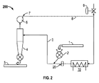
図1〜図9を参照しつつ、従来公知の乾燥装置の一タイプおよび本発明の乾燥装置について説明する。公知の乾燥装置の構造および作動方法の詳細のいくつかは先に述べられており、詳細な説明の概要は以下の通りである。たばこ製品をガス流で運搬および分散するダクト3内で、含水(湿潤状態の)たばこ製品から水分が除去される。サイクロン式分離器4は、たばこ製品を排気ガスから分離するように動作し、その排気ガスは処理および浄化または再循環され得る。
One type of conventionally known drying apparatus and the drying apparatus of the present invention will be described with reference to FIGS. Some of the details of the structure and operation of the known drying apparatus have been described above, and a summary of the detailed description follows. Moisture is removed from the wet (wet) tobacco product in a
本発明の実施形態の乾燥装置200、300、400、500は、図1に示される装置100と実質的に同様の構成要素をいくつか含んでいるため、同様の特徴は同一の参照番号を使用して参照される。図2を参照すると、本発明の第1の実施形態に従った乾燥装置200が示されており、回転エアロック2に先んじて、プロセスガスのダクト3内に位置する流量変更装置20を有している。流量変更装置はサイクロン式分離器の後に位置されてもよい。
Since the
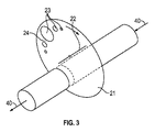
流量変更装置20は図3に示される実施形態で、回動自在ディスク21の機械的手段を備えるように示されている。ディスク21はプロセスガスの流れ方向40に対して平行な軸22を有する装置に回転可能に据え付けられている。ディスクは軸22を中心に据え付けられる。複数の孔23がディスクの外周に位置し、これらの孔の間に複数のランド部または固体領域24が存在する。プロセスガスダクト3は、ディスク21と据え付け用の軸22を収容する。
The flow
図4は、流量変更装置の断面図を示すと共に、ディスク21を駆動して該ディスクに軸22の周囲を回転させるための駆動手段50を伴ったディスク21を示す。この実施形態で、駆動手段は可変速度モータ50である。ディスク21は可変速度モータ50のシャフトに直接据え付けられている。固定ハウジング60はディスク21を包囲するように構成され、ディスク21をプロセスガスダクト3に連結する役割をし、流量変更装置ユニット内への、あるいは該ユニットからのガス漏洩を防ぐ。
FIG. 4 shows a cross-sectional view of the flow rate changing device and shows the
使用時、ディスク21はモータ50で駆動され、プロセスガスダクト3と横方向に交差する。方向40に向かって移動するプロセスガスは、孔23がダクト3と揃っている場合、孔23を通過でき、または、ディスク21の固体ランド部24がダクト3と揃っている場合、流れは妨害される。流れの波形は、ディスク21上の孔の形状またはパターンに応じて変化しうる。流れにおける変更の頻度はディスク21の回動速度によって、増加または減少可能である。
In use, the
流量変更装置の別の実施形態が図5に示される。この流量変更装置は、プロセスガスダクト3の製品の送り込みポイントより前、またはサイクロン式分離器の後に配置されたダンパー板25であって、プロセスガス流方向40に対して直角な回動軸26を有するダンパー板25である。ダンパー板25は長辺Lと短辺Hを有する長方形の板である。形状およびサイズは、互いに補うように(相補的に)選択されるが、プロセスダクト3の切断面(交差面)の高さおよび幅の内法と同一の形状ではない。ここでは、プロセスガスダクト3は直方体の形状で示される。ダンパー板25は、駆動モータ、またはダンパー板25を駆動して回動させる装置に取付けられ且つ連結される。
Another embodiment of a flow rate changing device is shown in FIG. This flow rate changing device is a
使用時、板が回動するにつれ、板はダクト3でのガス流の遮断と流通を交互に行う。板25の領域がダクト3の断面積と等しいまたは近似する場合、最小流量は実質的にゼロになろう。板25の領域がダクト3の領域よりも若干小さい場合、最小流量は比例的に最大流量に近づくであろう。
In use, the plate alternately blocks and flows the gas flow in the
図7は、ダクトの高さまたは直径HHに対する、幅寸法Wの変更による効果を図示している。速度グラフ27は、ダクト高さHHに対する板幅Hの割合が66%の場合の効果を表し、グラフ28は、板幅Hがダクト高さHHの50%に等しい場合の効果を表し、グラフ29はダクト高さHHの22%である板幅Hの効果を表している。これらのグラフでは、プロセスガスのファン速度は、全体を通じて同一の平均ガス流量を提供するように調整されていることが想定されている。同様の効果が、図3に示されるディスク21を伴う実施形態の、全面積に対する開口面積の割合を変更することにより得られうる。グラフ中の速度および時間の数字は例示を目的としており、これらの値に限定されない。
FIG. 7 illustrates the effect of changing the width dimension W on the height or diameter HH of the duct. The
上記のように、典型的には0.3Hzから5Hzの範囲の低周波ではあるがそれに限定されない範囲で操作することにより、乾燥装置内でのたばこ流が周期的に減速と加速を交互的に繰り返す状況を作り出すことが可能となる。この周期的又は循環的な速度低下は、2つの機能を実行する。即ち第1に、たばこ(製品)とガス流の間の相対速度が増大するため、熱伝達が増大する。第2に、たばこ(製品)が乾燥機内に滞留する時間が増加し、結果的に風味(維持)に有益な、より低温で乾燥プロセスを行うことを可能にする。 As described above, by operating in a low frequency range, typically between 0.3 Hz and 5 Hz, but not limited thereto, the tobacco flow in the drying apparatus alternates between deceleration and acceleration periodically. It is possible to create a repeating situation. This periodic or cyclical speed reduction performs two functions. That is, firstly, the relative speed between the cigarette (product) and the gas flow increases, so that heat transfer increases. Secondly, the time that the tobacco (product) stays in the dryer is increased, thus allowing the drying process to be performed at a lower temperature, which is beneficial to flavor (maintenance).
図6には、ダクト3に配置された流量変更装置20を含む、別の乾燥装置300が示される。ここでは、流量変更装置は、例えば、スウェーデン国マルメ(Malmo)のKockum Sonics社製のIKT150/360のような空気圧駆動式音波放射器などの音波放射器(sound emitter)90を備える。かかる音波放射器は、図6に示されるように、製品の送り込み位置の前の分岐ダクトを用いて、乾燥ダクトシステムに接続され得る。使用時、音波放射器は、ダクト3に沿って移動するプロセスガス流を変更する高周波パルスの流れを生成するであろう。1つまたはそれ以上の上記の流量変更装置20が、1つの乾燥システムおよび乾燥装置で使用されうることが想定される。このように、流れの低周波振動は、回動ディスク21またはダンパー25の機械的手段によって生成され、より高周波の音響振動は空気圧駆動式の音波放射器90によって生成される。
FIG. 6 shows another
別の実施形態では、ディスク21、板25および音波放射器90として説明された流量変更装置20はまた、図8及び図9に示された乾燥装置400、500で使用されてもよい。なお、乾燥装置400、500は、排気ガス流を凝結(凝縮)するための熱交換器12をさらに備え、アクセス吸気口11、アクセス排気口13、14、コンプレッサ16および蒸気監視装置17を有する。好ましい実施形態では、上記監視装置は蒸気流量計であり、コンプレッサは回動式ローブコンプレッサ(lobe compressor)である。乾燥装置は更に、分離して独立した蒸気供給器19、および追加的な蒸気をプロセス蒸気注入ライン15に提供するための蒸気注入システムを備える。蒸気注入システムは、流量計18、及び、蒸気監視装置17に対して応答する流量制御バルブ9を備える。
In another embodiment, the
乾燥機中の必要な低酸素濃度を維持するために、蒸気は適切な制御バルブおよび流量計測システムを介してシステムへと注入される。それについての例は当業者によく知られるところである。 In order to maintain the required low oxygen concentration in the dryer, steam is injected into the system via appropriate control valves and flow metering systems. Examples thereof are well known to those skilled in the art.
装置400、500は、従来の装置100について上述したようなやり方で動作する。乾燥装置100とは対照的に、7の地点における乾燥装置400からの排気ガスは、熱交換器12のシェル(殻、外殻)側の入口11に供給される水11を蒸発させる熱を(当該排気ガスが)提供するところの熱交換器12に向かう。レベルセンサ制御器(図示略)は、電熱面は被覆されるものの、熱交換器12からプロセス蒸気注入ライン15へと水が放出されること(可能性)がないように、熱交換器12内の水位を維持する。熱交換器12内の圧力は、大気圧未満に維持され、好ましい実施形態では絶対圧0.5バールに維持される。陰圧(負圧)がコンプレッサ16によって生成される。この低圧において、65℃から75℃の間であって、70℃前後の温度の熱交換器によって蒸気が生成され、これにより、排気ガス中の蒸気の潜熱含量を回収する。言い換えると、乾燥プロセスの排気ガス混合物における熱エネルギーは、熱交換器12を用いて低圧の蒸気を生成するのに使用される。
The
この、水や他の内容物を含まない低圧蒸気は、次いでコンプレッサ16によって機械的に圧縮され、プロセスガスに注入され、所望の蒸気濃度を維持する。低圧蒸気は、コンプレッサ16によって絶対圧1バールより大きい圧力に圧縮される。1バールを超える圧力は、プロセスライン、乾燥プロセスおよびプロセス加熱器段階10に蒸気を注入して戻すのに適していることが判明している。ダクト3および分離器4に注入される蒸気流れは、蒸気流量計17からのフィードバックに従い、コンプレッサ16の速度を変更することによって制御される。コンプレッサ16からの蒸気流量が望ましい蒸気流量を下回る場合、分離した供給源19からの追加的蒸気の適切な流れを供給するために、流量計18及び流量制御バルブ9からなるところの独立した蒸気注入システムが使用され得る。この好ましい実施形態では、分離供給源19は中央ボイラー設備であり、それは総蒸気注入流量を既定の望ましいレベルにまで導くべく蒸気を提供する。すべての排気流が熱交換器によって凝結(凝縮)されるわけではない。とりわけ排気ガスの空気含量は、熱交換器12の凝縮器から排気口14を介して放出される。排気口7および14における排気ガスおよび過剰ガスは、飽和状態の熱交換器12から放出されることから、蒸気成分を含む。上記のとおり、排気ガスは、ガスを浄化し、および/または悪臭成分を除去するために、追加の処理を要する場合がある。また、水は、出口13にて熱交換器12から排出される(熱交換器では、凝結にかかる潜熱を出しながら水が凝縮する)。「ガス流」という言葉によって、我々は、たばこ製品、ガス、蒸気、不純物、および場合によっては水を、システムを通じて運搬(搬送)するところの乾燥装置での流体流動を意味するものである。
This low pressure steam, free of water and other contents, is then mechanically compressed by
図9を参照すると、本発明の更なる実施例に従った、流量変更装置20を伴う乾燥装置500が示されている。本発明の実施形態の乾燥装置400、500は実質的に同様であり、同様の特徴は同一の参照番号を用いて参照される。乾燥装置500の構成は、コンプレッサ16が熱交換器12の上流に位置している点で、乾燥装置400とは異なる。コンプレッサ16、つまりは乾燥の圧縮段階は、熱交換器12の前で起きる。この実施形態では、蒸気から空気を除去するために、この好ましい実施形態の熱交換器12のような手段により、排気ガスは、乾燥プロセスに蒸気として再注入される直前に再圧縮される。したがって、回収されたガスおよびエネルギーの温度は、乾燥プロセスでの使用に有益なレベルにまで上昇される。
Referring to FIG. 9, there is shown a
本発明の範囲を逸脱することなく、上記の実施形態に対し様々な修正がなされてもよい。異なる数の乾燥段階、またはコンプレッサ、または熱交換手段があってもよい。2つ以上の分離器があってもよい。さらに、運転施設から完全に外部の容器または供給器のような、他のタイプの独立蒸気源が使用されてもよい。エネルギー回収の効率は必要に応じて最適化することができ、数多くの詳細な設計上の考慮事項に依存する。乾燥されるべき材料は、繊維性または粒状であってもよく、有機材料を含んでもよい。ここで、ダクトは円で示されている。別の形状のダクトが使用されてもよい。例えば、円形または長方形などのいかなる使いやすい断面であってもよい。空気圧駆動式の音波放射器が説明されているが、これは電気的に駆動されてもよく、または他の手段、他のエネルギー供給、または他の周波数帯域で駆動されてもよい。 Various modifications may be made to the above-described embodiments without departing from the scope of the present invention. There may be different numbers of drying stages, or compressors, or heat exchange means. There may be more than one separator. In addition, other types of independent steam sources may be used, such as containers or feeders that are completely external from the operating facility. The efficiency of energy recovery can be optimized as needed and depends on a number of detailed design considerations. The material to be dried may be fibrous or granular and may include organic materials. Here, the duct is indicated by a circle. Other shaped ducts may be used. For example, any easy-to-use cross section such as a circle or a rectangle may be used. Although a pneumatically driven sound emitter has been described, it may be electrically driven or driven by other means, other energy supplies, or other frequency bands.
図7中、「Gas Velocity m/s」は、ガス速度 m/秒、「Time (Seconds)」は、時間(秒)。 In FIG. 7, “Gas Velocity m / s” is the gas velocity m / s, and “Time (Seconds)” is the time (seconds).
Claims (15)
第1のガス流および繊維性材料を加熱するように構成された加熱器であって、当該第1のガス流は吸気口で乾燥装置に流入するように構成され、当該ガス流は蒸気を含んでいる、加熱器と、
前記第1のガス流から前記繊維性材料を分離して第2のガス流を形成する分離器と、
前記第2のガス流を前記プロセス加熱器および蒸気注入装置へと再循環させるように構成されたファン及びダクトと、
前記第1のガス流におけるガス流れを変更するように構成された流量変更装置と、
を備えることを特徴とする乾燥装置。 A drying device for drying a fibrous or granular material,
A heater configured to heat a first gas stream and a fibrous material, wherein the first gas stream is configured to flow into a drying device at an inlet, the gas stream including steam. A heater,
A separator that separates the fibrous material from the first gas stream to form a second gas stream;
A fan and a duct configured to recirculate the second gas stream to the process heater and a steam injector;
A flow rate changing device configured to change a gas flow in the first gas flow;
A drying apparatus comprising:
前記流量変更装置は、プロセスの流れの方向に対して直交する回転軸を有する回動自在なディスクまたはチョッパーを備える、ことを特徴とする請求項6に記載の乾燥装置。 The first gas stream and the fibrous material have a flow direction of the process (drying process);
The drying apparatus according to claim 6, wherein the flow rate changing device includes a rotatable disk or chopper having a rotation axis orthogonal to a process flow direction.
前記流量変更装置は、プロセスの流れの方向に対して直交する回転軸を有する回動自在なダンパー板を備える、ことを特徴とする請求項6に記載の乾燥装置。 The first gas stream and the fibrous material have a flow direction of the process (drying process);
The drying apparatus according to claim 6, wherein the flow rate changing device includes a rotatable damper plate having a rotation axis orthogonal to a process flow direction.
Applications Claiming Priority (3)
| Application Number | Priority Date | Filing Date | Title |
|---|---|---|---|
| GB1303570.4 | 2013-02-28 | ||
| GB1303570.4A GB2511331A (en) | 2013-02-28 | 2013-02-28 | Drying Apparatus |
| PCT/GB2014/050421 WO2014132031A1 (en) | 2013-02-28 | 2014-02-13 | Drying apparatus |
Publications (1)
| Publication Number | Publication Date |
|---|---|
| JP2016508596A true JP2016508596A (en) | 2016-03-22 |
Family
ID=48092257
Family Applications (1)
| Application Number | Title | Priority Date | Filing Date |
|---|---|---|---|
| JP2015559553A Pending JP2016508596A (en) | 2013-02-28 | 2014-02-13 | Drying equipment |
Country Status (5)
| Country | Link |
|---|---|
| JP (1) | JP2016508596A (en) |
| CN (1) | CN105264319A (en) |
| GB (1) | GB2511331A (en) |
| HK (1) | HK1218153A1 (en) |
| WO (1) | WO2014132031A1 (en) |
Cited By (1)
| Publication number | Priority date | Publication date | Assignee | Title |
|---|---|---|---|---|
| JP2020041780A (en) * | 2018-09-13 | 2020-03-19 | 王子ホールディングス株式会社 | Powder drying apparatus and powder drying method |
Families Citing this family (7)
| Publication number | Priority date | Publication date | Assignee | Title |
|---|---|---|---|---|
| CN104886748A (en) * | 2015-04-30 | 2015-09-09 | 广东中烟工业有限责任公司 | Two-segment cylinder cut-tobacco drier with independent temperature control function |
| CN106482498A (en) * | 2016-12-27 | 2017-03-08 | 文安县天华密度板有限公司 | A kind of Processes and apparatus of wood-based plate drying system environmental protection and energy saving |
| DE102019002671A1 (en) * | 2019-04-11 | 2020-10-15 | Grenzebach Bsh Gmbh | Method for drying sheet materials and drying device |
| CN110145923B (en) * | 2019-05-09 | 2021-07-09 | 安徽卓尔电器有限公司 | A kind of injection molding raw material drying equipment and method |
| CN115773652A (en) * | 2022-12-14 | 2023-03-10 | 隆回县双龙生物质颗粒能源开发有限公司 | Biomass raw material drying equipment with airflow-driven powder circulation |
| CN117600078B (en) * | 2023-12-06 | 2025-10-14 | 安徽中烟工业有限责任公司 | A method for characterizing the processing strength of a two-stage air separator for leaf shreds |
| WO2026083231A1 (en) * | 2024-10-15 | 2026-04-23 | Comas - Costruzioni Macchine Speciali - S.P.A. | Plant and method for drying a material of plant origin |
Family Cites Families (21)
| Publication number | Priority date | Publication date | Assignee | Title |
|---|---|---|---|---|
| DE975272C (en) * | 1955-05-01 | 1961-10-26 | Benno Schilde Maschb Ag | Method, application of the same and device for its implementation for treating such as drying, cooling, moistening or the like of suspended goods |
| DE3305670C2 (en) * | 1983-02-18 | 1986-06-05 | B.A.T. Cigaretten-Fabriken Gmbh, 2000 Hamburg | Device for drying tobacco materials |
| US4706390A (en) * | 1986-04-14 | 1987-11-17 | John A. Kitchen Ltd. | Dehydrator |
| US4881574A (en) * | 1988-08-12 | 1989-11-21 | The United States Of America As Represented By The Department Of Energy | Enclosed rotary disc air pulser |
| JP3140039B2 (en) * | 1990-11-07 | 2001-03-05 | 日本たばこ産業株式会社 | Flash drying method and apparatus for tobacco raw materials |
| JPH06312158A (en) * | 1993-04-30 | 1994-11-08 | Matsui Mfg Co | Air vibration wave generation method and apparatus |
| US5658142A (en) * | 1995-02-14 | 1997-08-19 | Novadyne Ltd. | Material drying system |
| AT404876B (en) * | 1995-05-16 | 1999-03-25 | Andritz Patentverwaltung | METHOD FOR DRYING DAMP GOODS, ESPECIALLY WOOD FIBERS, AND SYSTEM FOR CARRYING OUT THIS METHOD |
| US5638609A (en) * | 1995-11-13 | 1997-06-17 | Manufacturing And Technology Conversion International, Inc. | Process and apparatus for drying and heating |
| WO1999064801A1 (en) * | 1998-06-11 | 1999-12-16 | Universal Dynamics, Inc. | Method and apparatus for drying granular solids with venturi powered gas circulation |
| DE19909318C2 (en) * | 1999-03-03 | 2001-06-28 | Bat Cigarettenfab Gmbh | Method and device for expanding tobacco material |
| US6219234B1 (en) * | 1999-03-30 | 2001-04-17 | International Business Corporation | Method for using pulsating flow to improve thermal transport in systems |
| RU2280220C2 (en) * | 2001-11-26 | 2006-07-20 | Джапан Тобакко Инк. | Instantaneous drier for material in the form of particles |
| DE10350838A1 (en) * | 2003-10-28 | 2005-06-02 | Hauni Maschinenbau Ag | Method for cooling a drying device for a tobacco product and correspondingly controlled drying device |
| DE102005015781A1 (en) * | 2005-04-01 | 2006-10-05 | Hauni Maschinenbau Ag | Method and device for drying a fibrous material |
| PL378287A1 (en) * | 2005-12-06 | 2007-06-11 | International Tobacco Machinery Poland Ltd | Method and system for the conditioning of cellular materials, and the materials of vegetable origin in particular |
| CN201207913Y (en) * | 2008-07-08 | 2009-03-18 | 中国烟草总公司郑州烟草研究院 | Airflow drying equipment for tobacco |
| CN201219480Y (en) * | 2008-07-08 | 2009-04-15 | 中国烟草总公司郑州烟草研究院 | Pulse airflow drying equipment for tobacco material |
| GB0902629D0 (en) * | 2009-02-17 | 2009-04-01 | Dickinson Legg Ltd | Tabacco drying apparatus |
| DE102009028913A1 (en) * | 2009-08-26 | 2011-03-31 | Jt International S.A. | Apparatus and method for treating tobacco |
| SE537079E (en) * | 2010-12-10 | 2018-02-20 | Outotec Oyj | A method of controlling a steam dryer, a steam dryer and a bioenergy combination, and the use of the method. |
-
2013
- 2013-02-28 GB GB1303570.4A patent/GB2511331A/en not_active Withdrawn
-
2014
- 2014-02-13 CN CN201480011169.5A patent/CN105264319A/en active Pending
- 2014-02-13 HK HK16106093.5A patent/HK1218153A1/en unknown
- 2014-02-13 WO PCT/GB2014/050421 patent/WO2014132031A1/en not_active Ceased
- 2014-02-13 JP JP2015559553A patent/JP2016508596A/en active Pending
Cited By (2)
| Publication number | Priority date | Publication date | Assignee | Title |
|---|---|---|---|---|
| JP2020041780A (en) * | 2018-09-13 | 2020-03-19 | 王子ホールディングス株式会社 | Powder drying apparatus and powder drying method |
| JP7322367B2 (en) | 2018-09-13 | 2023-08-08 | 王子ホールディングス株式会社 | Powder drying apparatus and powder drying method |
Also Published As
| Publication number | Publication date |
|---|---|
| GB2511331A (en) | 2014-09-03 |
| WO2014132031A1 (en) | 2014-09-04 |
| GB201303570D0 (en) | 2013-04-10 |
| HK1218153A1 (en) | 2017-02-03 |
| CN105264319A (en) | 2016-01-20 |
Similar Documents
| Publication | Publication Date | Title |
|---|---|---|
| JP2016508596A (en) | Drying equipment | |
| EP2399092B1 (en) | Drying apparatus with energy recuperation | |
| US3490201A (en) | Method and apparatus for drying gases | |
| CA1252012A (en) | Treatment of tobacco | |
| US10240865B2 (en) | Non-thermal drying systems and methods using vacuum throttle flash generators and processing vessels | |
| JP3925931B2 (en) | Humidity control method and humidity controller for raw materials | |
| US9309477B2 (en) | System for removing surface moisture from coal | |
| AU2007247801A1 (en) | Indirect-heat thermal processing of particulate material | |
| CN205850536U (en) | A kind of tower tail gas treatment device | |
| JP2005140497A (en) | Method and apparatus for controlling the flow rate of gas passing through particulate matter in a drying hopper | |
| CN102834684A (en) | Spray drying apparatus | |
| EP2962050A1 (en) | Drying apparatus | |
| WO2018109144A1 (en) | Plant and process for production of a dried product from a humid product | |
| US4260368A (en) | Process and a device for treatment of biologic fuels | |
| CN104194857B (en) | Biomass raw material treatment method and system thereof | |
| WO2009153842A1 (en) | Drying apparatus | |
| CN223710120U (en) | A high-efficiency chemical drying equipment | |
| EP1795843B1 (en) | Method and apparatus for conditioning of cellular materials, in particular organic materials | |
| RU2304265C1 (en) | Spraying dryer | |
| CN212619958U (en) | Closed self-circulating drying system | |
| CN113840959B (en) | Method and apparatus for making paper or pulp | |
| US20070125394A1 (en) | Apparatus for conditioning of organic materials | |
| RU2305236C1 (en) | Chamber drier | |
| US242903A (en) | Thirds to isaac w | |
| JP2025150906A (en) | Smoking device and smoking method |
Legal Events
| Date | Code | Title | Description |
|---|---|---|---|
| RD01 | Notification of change of attorney |
Free format text: JAPANESE INTERMEDIATE CODE: A7426 Effective date: 20151215 |
|
| A521 | Request for written amendment filed |
Free format text: JAPANESE INTERMEDIATE CODE: A821 Effective date: 20151215 |