JP2016525439A - Lost core molded polymer golf club head - Google Patents
Lost core molded polymer golf club head Download PDFInfo
- Publication number
- JP2016525439A JP2016525439A JP2016533297A JP2016533297A JP2016525439A JP 2016525439 A JP2016525439 A JP 2016525439A JP 2016533297 A JP2016533297 A JP 2016533297A JP 2016533297 A JP2016533297 A JP 2016533297A JP 2016525439 A JP2016525439 A JP 2016525439A
- Authority
- JP
- Japan
- Prior art keywords
- core
- club head
- face
- golf club
- flange
- Prior art date
- Legal status (The legal status is an assumption and is not a legal conclusion. Google has not performed a legal analysis and makes no representation as to the accuracy of the status listed.)
- Granted
Links
Images






Classifications
-
- A—HUMAN NECESSITIES
- A63—SPORTS; GAMES; AMUSEMENTS
- A63B—APPARATUS FOR PHYSICAL TRAINING, GYMNASTICS, SWIMMING, CLIMBING, OR FENCING; BALL GAMES; TRAINING EQUIPMENT
- A63B53/00—Golf clubs
- A63B53/04—Heads
-
- A—HUMAN NECESSITIES
- A63—SPORTS; GAMES; AMUSEMENTS
- A63B—APPARATUS FOR PHYSICAL TRAINING, GYMNASTICS, SWIMMING, CLIMBING, OR FENCING; BALL GAMES; TRAINING EQUIPMENT
- A63B53/00—Golf clubs
- A63B53/04—Heads
- A63B53/0458—Heads with non-uniform thickness of the impact face plate
-
- A—HUMAN NECESSITIES
- A63—SPORTS; GAMES; AMUSEMENTS
- A63B—APPARATUS FOR PHYSICAL TRAINING, GYMNASTICS, SWIMMING, CLIMBING, OR FENCING; BALL GAMES; TRAINING EQUIPMENT
- A63B53/00—Golf clubs
- A63B53/04—Heads
- A63B53/0466—Heads wood-type
-
- A—HUMAN NECESSITIES
- A63—SPORTS; GAMES; AMUSEMENTS
- A63B—APPARATUS FOR PHYSICAL TRAINING, GYMNASTICS, SWIMMING, CLIMBING, OR FENCING; BALL GAMES; TRAINING EQUIPMENT
- A63B60/00—Details or accessories of golf clubs, bats, rackets or the like
- A63B60/02—Ballast means for adjusting the centre of mass
-
- B—PERFORMING OPERATIONS; TRANSPORTING
- B29—WORKING OF PLASTICS; WORKING OF SUBSTANCES IN A PLASTIC STATE IN GENERAL
- B29C—SHAPING OR JOINING OF PLASTICS; SHAPING OF MATERIAL IN A PLASTIC STATE, NOT OTHERWISE PROVIDED FOR; AFTER-TREATMENT OF THE SHAPED PRODUCTS, e.g. REPAIRING
- B29C45/00—Injection moulding, i.e. forcing the required volume of moulding material through a nozzle into a closed mould; Apparatus therefor
- B29C45/17—Component parts, details or accessories; Auxiliary operations
- B29C45/40—Removing or ejecting moulded articles
- B29C45/44—Removing or ejecting moulded articles for undercut articles
- B29C45/4457—Removing or ejecting moulded articles for undercut articles using fusible, soluble or destructible cores
-
- A—HUMAN NECESSITIES
- A63—SPORTS; GAMES; AMUSEMENTS
- A63B—APPARATUS FOR PHYSICAL TRAINING, GYMNASTICS, SWIMMING, CLIMBING, OR FENCING; BALL GAMES; TRAINING EQUIPMENT
- A63B53/00—Golf clubs
- A63B53/04—Heads
- A63B2053/0491—Heads with added weights, e.g. changeable, replaceable
-
- B—PERFORMING OPERATIONS; TRANSPORTING
- B29—WORKING OF PLASTICS; WORKING OF SUBSTANCES IN A PLASTIC STATE IN GENERAL
- B29C—SHAPING OR JOINING OF PLASTICS; SHAPING OF MATERIAL IN A PLASTIC STATE, NOT OTHERWISE PROVIDED FOR; AFTER-TREATMENT OF THE SHAPED PRODUCTS, e.g. REPAIRING
- B29C45/00—Injection moulding, i.e. forcing the required volume of moulding material through a nozzle into a closed mould; Apparatus therefor
- B29C45/14—Injection moulding, i.e. forcing the required volume of moulding material through a nozzle into a closed mould; Apparatus therefor incorporating preformed parts or layers, e.g. injection moulding around inserts or for coating articles
- B29C45/14336—Coating a portion of the article, e.g. the edge of the article
Landscapes
- Health & Medical Sciences (AREA)
- General Health & Medical Sciences (AREA)
- Physical Education & Sports Medicine (AREA)
- Engineering & Computer Science (AREA)
- Mechanical Engineering (AREA)
- Manufacturing & Machinery (AREA)
- Life Sciences & Earth Sciences (AREA)
- Wood Science & Technology (AREA)
- Golf Clubs (AREA)
Abstract
ゴルフクラブヘッドを形成する方法が、第1の融解温度を有する材料からゴルフクラブヘッドのコアを形成するステップとコアにクラブフェイスを固着させるステップとを含む。クラブフェイスは、第1の打撃面、第1の面の反対側にある第2の面、及びロック特徴部を含む。次に、本体が、コアの周囲に、本体がロック特徴部の少なくとも一部を取り囲むように成形され、本体は、第1の融解温度よりも高い第2の融解温度を有するポリマー材料から形成される。最後に、本体内からコアが除去される。A method of forming a golf club head includes forming a golf club head core from a material having a first melting temperature and securing the club face to the core. The club face includes a first striking surface, a second surface opposite the first surface, and a locking feature. The body is then shaped around the core such that the body surrounds at least a portion of the locking feature, and the body is formed from a polymeric material having a second melting temperature that is higher than the first melting temperature. The Finally, the core is removed from within the body.
Description
本発明は、概して、ロストコア成形を用いてゴルフクラブヘッド内の空洞を形成するための製造技法に関する。なお、本願は、2013年8月5日に出願された米国特許仮出願第61/862,341号の利益を主張するものであり、上記仮出願の全体が本願の参照となる。 The present invention generally relates to manufacturing techniques for forming cavities in golf club heads using lost core molding. This application claims the benefit of US Provisional Patent Application No. 61 / 862,341, filed on August 5, 2013, and the entire provisional application is a reference to this application.
ゴルフクラブは、概して、長細のシャフトの端部に配置されたゴルフクラブヘッドを含む。プレーの際に、地面に置かれているボールに当てることを意図してゴルフクラブが振られると、所望の方向及び所望の垂直方向の弾道を描くようにボールが打ち上げられる。この衝突によって、クラブフェイスに瞬間的な衝突力が生じ、この衝突力のピークは、約6520N〜約18000N(約1520lbf〜約4000lbf)の範囲内の大きさとなり得る。 Golf clubs generally include a golf club head disposed at the end of an elongated shaft. When a golf club is shaken with the intention of hitting a ball placed on the ground during play, the ball is launched in a desired direction and a desired vertical trajectory. This impact creates an instantaneous impact force on the club face, and the peak of the impact force can be in the range of about 6520 N to about 18000 N (about 1520 lbf to about 4000 lbf).
ゴルフクラブヘッドを形成する際には、多くの設計パラメータを考慮する必要がある。設計は、例えば、クラブと地面との間はもちろんクラブヘッドとボールとの間の繰り返しの衝撃に充分に耐える構造上の復元力(柔軟性)を提示する必要がある。クラブヘッドは、様々なルール設定協会が決める最大の寸法要求に適合するものでなければならない。また、(適用基準に準拠した測定で)予め定められた最大値よりも高い反発係数を有してはいけない。予め定められた特定の設計の制約条件を満たした場合に、クラブヘッド設計は一般に、重心の規模及び位置と、重心及び/又はシャフトの周りのヘッドの慣性モーメントによって定量される。 Many design parameters need to be considered when forming a golf club head. The design, for example, needs to present a structural resiliency (flexibility) that is sufficient to withstand repeated impacts between the club head and the ball as well as between the club and the ground. Club heads must meet the maximum dimensional requirements set by various rule-setting associations. Also, it should not have a coefficient of restitution higher than a predetermined maximum value (by measurement according to applicable standards). A club head design is generally quantified by the scale and position of the center of gravity and the moment of inertia of the head around the center of gravity and / or shaft, when certain predetermined design constraints are met.
クラブの慣性モーメントは、クラブの(特には、芯を外した打撃をした際の)回転抵抗に関連し、クラブの「許容(寛容)度」の測定値として認識されることが多い。典型的なクラブ設計においては、ボールを押したりボールの勢いをなくしたりするクラブの傾向を低減させるために、高い慣性モーメントが求められている。高い慣性モーメントは、概して、(重心の周りの慣性モーメントを最大にするために)クラブの周縁のできるだけ近くにウェイト(重り)を動かすことにより、さらに言えば(シャフトの周りの慣性モーメントを最大にするために)つま先のできるだけ近くにウェイトを移すことにより実現される。 The moment of inertia of a club is related to the club's rotational resistance (especially when hitting off-center) and is often recognized as a measure of the club's “tolerance”. In a typical club design, a high moment of inertia is required to reduce the club's tendency to push the ball or remove the ball's momentum. A high moment of inertia is generally achieved by moving the weight (weight) as close as possible to the periphery of the club (to maximize the moment of inertia around the center of gravity), and further speaking (maximizing the moment of inertia around the shaft). This is accomplished by moving the weight as close as possible to the toes.
慣性モーメントがクラブヘッドの許容度に影響を与える一方で、クラブフェイスの後側の位置(及びソールよりも高い位置)は、概して、所与のフェイス・ロフト角についての弾道に影響を与える。(フェイスからずっと離れた)できるだけ後方かつ下方の(ソール付近の)位置に重心があることにより、一般に、重心がより前方かつ/或いは上方の位置にあるクラブヘッドと比較して、高い弾道を描くようなボールの軌跡となる。 While the moment of inertia affects club head tolerance, the position behind the club face (and higher than the sole) generally affects the trajectory for a given face loft angle. Having a center of gravity at a position as far back and below (near the sole) as possible (far from the face) generally provides a higher trajectory than a club head with a center of gravity in a more forward and / or upper position. It becomes the trajectory of the ball.
クラブヘッドの周縁の重量を増大させることにより高い慣性モーメントが得られる一方で、クラブヘッドの総質量/スウィング(すなわち、重心の規模)の拡大は、クラブヘッドスピードと飛距離に大きな負の影響を与える。換言すれば、クラブヘッドスピード(及び飛距離)を最大にするためには、総質量を小さくすることが要求される。しかし、総質量を小さくすると、概して、クラブヘッドの慣性モーメント(及び許容度)が減少してしまう。 Increasing the weight of the club head periphery increases the moment of inertia, while increasing the club head's total mass / swing (ie, the scale of the center of gravity) has a significant negative impact on club head speed and distance. give. In other words, to maximize the club head speed (and flight distance), it is required to reduce the total mass. However, reducing the total mass generally reduces the club head's moment of inertia (and tolerance).
スウィングスピード(質量)と許容度(慣性モーメント)とを両立させることに関しては、クラブヘッド全体に亘って特定の位置ごとに変化する質量を付して、特定のゴルファー又は能力レベルに応じてクラブの性能をカスタマイズすることが望ましい。この態様においては、クラブヘッドの総質量は、概して、構造上の質量と、裁量に委ねられた質量と、の2つのカテゴリーに分類され得る。 In order to achieve both swing speed (mass) and tolerance (moment of inertia), a mass that varies from position to position over the entire club head is added to the club according to the specific golfer or ability level. It is desirable to customize performance. In this aspect, the total mass of the club head can generally be divided into two categories: structural mass and discretionary mass.
構造上の質量とは、概して、繰り返しの衝撃に耐えるのに必要とされる構造上の復元力を有するクラブヘッドを提供するために要求される材料の質量のことである。構造上の質量は、設計に依存する度合いが高く、具体的な質量分布と比較して設計上で制御可能な程度が低い。他方で、裁量に委ねられた質量は、ソールがクラブの性能及び/又は許容度をカスタマイズすることを目的として、クラブヘッドの設計に加えられる追加の質量である。理想的なクラブの設計においては、消費者が期待するスウィング重量を維持しつつ、クラブの性能をカスタマイズするための大きな能力を設計者に与えるために、(弾性を犠牲にすることなく)構造上の質量が最小限に抑えられる。 Structural mass generally refers to the mass of material required to provide a club head with the structural resilience required to withstand repeated impacts. The structural mass is highly dependent on the design and is less controllable on the design than a specific mass distribution. On the other hand, the discretionary mass is an additional mass added to the club head design for the purpose of customizing the performance and / or tolerance of the club. In an ideal club design, structurally (without sacrificing elasticity) to give the designer a great ability to customize the performance of the club while maintaining the swing weight that consumers expect. The mass of is minimized.
構造上の総質量を最小限に抑えるために、ほとんどのメタル・ウッドは典型的には、高強度の軽金属合金から形成された薄いメタルフェイスと、中空な構造上のシェルとを使用している。このような設計は、構造上の質量を減少させるのに有効であるが、複雑で多段の製造プロセスを伴うことがあり、最先端の合金には莫大な費用がかかる為にさらなる改良が制限され得る。 To minimize the total structural mass, most metal woods typically use a thin metal face formed from a high strength light metal alloy and a hollow structural shell. . Such a design is effective in reducing structural mass, but may involve complex and multi-stage manufacturing processes, and state-of-the-art alloys are expensive and limit further improvements. obtain.
別の設計ファクタが、クラブ用に選択されるフェイス・スタイルの型式に関係する。メタル・ウッドにおいては、設計のほとんどは、カップ・フェイス設計かエッジ溶接設計のいずれかに分類することができる。エッジ溶接設計には、通常、打撃面を形成するために、クラブの前方のフェイス部に溶着されるほぼ平坦な金属板が含まれる。この金属板は、通常、わずかな凹所に嵌め込まれ、金属板の縁部又は縁部付近で本体に溶接又は溶着される。 Another design factor is related to the face style type selected for the club. In metal wood, most designs can be classified as either cup face designs or edge weld designs. Edge weld designs typically include a substantially flat metal plate that is welded to the front face of the club to form a striking surface. This metal plate is usually fitted in a slight recess and welded or welded to the body at or near the edge of the metal plate.
カップ・フェイス設計は同様の金属板/打撃面を含むが、金属板は、前方のフェイス部のすぐ向こう側の位置であって、本体のソール/スカート/クラウン上の位置に延在する。このような設計は、溶接線後部を打撃面の後ろに延長する。このようにして、カップ・フェイス設計は、少し大きい可能な打撃面を提供することができ、溶接縁部、又は本体の一部がボールによって直接衝撃を受ける可能性を低減する。 The cup face design includes a similar metal plate / striking surface, but the metal plate extends just beyond the front face and to a position on the sole / skirt / crown of the body. Such a design extends the rear of the weld line behind the striking surface. In this way, the cup face design can provide a slightly larger possible striking surface, reducing the likelihood that the weld edge, or part of the body, will be directly impacted by the ball.
ゴルフクラブヘッドを形成する方法は、第1の融解温度(融点)を有する材料からゴルフクラブヘッドのコアを形成すること、及びコアにクラブフェイスを固着させることと、を含む。クラブフェイスは、第1の打撃面、第1の面とは反対側の第2の面、及びロック特徴部を含む。次に、ロック特徴部の少なくとも一部を取り囲むように、本体がコアの周囲に型成形され、本体は、第1の融解温度よりも高い第2の融解温度を有するポリマー材料から形成される。最後に、コアは、融解つまり溶融などによって本体内から除去される。 A method of forming a golf club head includes forming a golf club head core from a material having a first melting temperature (melting point) and securing a club face to the core. The club face includes a first striking surface, a second surface opposite the first surface, and a locking feature. Next, a body is molded around the core so as to surround at least a portion of the locking feature, and the body is formed from a polymeric material having a second melting temperature that is higher than the first melting temperature. Finally, the core is removed from within the body, such as by melting or melting.
一構成においては、本体にフェイスを固着させるために使用されるロック特徴部はフランジを含む。フランジは、第1の打撃面の一部に対してほぼ平行(すなわち、約30°の範囲内で平行)に延在し、第2の面からある距離だけ離間して配置されているとよい。従って、本体がロック特徴部の少なくとも一部を取り囲むように本体を型成形することは、ポリマー材料をフランジの両側に流して本体を型成形することを含み得る。このことは、本体とクラブフェイスとの間の機械的干渉をもたらすことができ、それによってクラブフェイスと本体との間のすべての相対的平行移動(ずれ)を妨げる。一構成においては、型成形は、射出成形プロセスによって、例えば、コア及びクラブフェイスを型の中に配置し、型と上記コアとの間にポリマー材料を射出成形することによって、行うことができる。 In one configuration, the locking feature used to secure the face to the body includes a flange. The flange may extend substantially parallel to a portion of the first striking surface (ie, parallel within a range of about 30 °) and be spaced a distance from the second surface. . Accordingly, molding the body such that the body surrounds at least a portion of the locking feature may include casting the polymer material on both sides of the flange to mold the body. This can result in mechanical interference between the body and the club face, thereby preventing any relative translation (displacement) between the club face and the body. In one configuration, molding can be performed by an injection molding process, for example, by placing a core and club face in a mold and injection molding a polymer material between the mold and the core.
一実施例においては、ゴルフクラブヘッドアセンブリが、コア、クラブフェイス、及びポリマー製の本体を含み得る。コアは、第1の融解温度を有する第1の材料から形成することができる。クラブフェイスはコアに固着されてもよく、第1の打撃面、第1の面の反対側にある第2の面、及び第2の面から横断方向に離間して配置されたフランジを含み得る。 In one example, a golf club head assembly may include a core, a club face, and a polymer body. The core can be formed from a first material having a first melting temperature. The club face may be secured to the core and may include a first striking surface, a second surface opposite the first surface, and a flange disposed transversely spaced from the second surface. .
ポリマー製の本体は、コアの周り及びフランジの両側に配置される。ポリマー製の本体は、第1の融解温度よりも高い第2の融解温度を有する。コアは、コアを第1の融解温度と第2の融解温度との間の温度まで加熱することにより、又は溶剤を使用することによりポリマー製の本体から除去されるように構成される。 A polymer body is placed around the core and on both sides of the flange. The polymeric body has a second melting temperature that is higher than the first melting temperature. The core is configured to be removed from the polymeric body by heating the core to a temperature between a first melting temperature and a second melting temperature, or by using a solvent.
フランジは、第1の面の一部に対して約±30°の範囲内で平行に延在し、フランジの両側に配置されたポリマー製の本体は、クラブフェイスと該本体との間のすべての相対的平行移動を妨げるように、該本体とクラブフェイスとの間の機械的干渉となる。一構成においては、フランジは、第1の面と第2の面のうちの少なくとも一方の周縁と整列した単一の連続的なフランジである。 The flange extends parallel to a portion of the first face within a range of about ± 30 °, and the polymer body disposed on both sides of the flange is all between the club face and the body. Mechanical interference between the body and the club face so as to prevent relative translation. In one configuration, the flange is a single continuous flange aligned with the periphery of at least one of the first and second surfaces.
各図に亘って同様の参照符号は同一の又は対応する構成要素を示す。図1は、一般にフェイス部12(すなわち「フェイス12」)及び本体部分14(すなわち「本体14)」を含むウッド型式のゴルフクラブヘッド10(すなわち「クラブヘッド10」)の概略を示す斜視図である。図2に概ね示されているように、クラブヘッド10は長細のシャフト16の端部に取り付けられており、この長細のシャフト16をユーザが握って振ることにより、クラブヘッド10が弧を描くように動く。
Like reference symbols in the various drawings indicate identical or corresponding components. FIG. 1 is a perspective view schematically illustrating a wood-type golf club head 10 (ie, “
クラブヘッド10のフェイス12は概して、通常のスイングの際にゴルフボールと接触するよう意図された打撃(ヒット)面18を画定する。打撃面18は平面状である場合もあれば、クラブヘッド10から延出する少し凸状/円弧状の湾曲を有する場合もある。さらに周知のように、打撃面18は、クラブがニュートラル(中立的)な打撃位置に保持されているときに、垂直面に対してある角度で配置され得る。この角度は一般にロフト角と呼ばれつまりはクラブの傾斜のことである。ウッド型式のクラブヘッド(ハイブリッドウッドを含む)は、典型的には約8.5°〜約24°のロフト角を有するが、他のロフト角とすることも可能であり、実際に市販されているものもある。
The
クラブヘッド10の本体14は概して、フェイス12を支持するとともに、フェイス12と長細のシャフト16との間に連結手段を設けるように構成され得る。再び図1を参照すると、本体14は、一般に、下方(低位)部分20(すなわち「ソール20」)と、上方部分22(すなわち「クラウン22」)と、一般にソール20をクラウン22に連結する側部分24(すなわち「スカート24」)と、長細のシャフト16を受け且つ/或いはその他の方法で長細のシャフト16と連結するように構成されたホーゼル28と、を含み得る。エッジ溶接式クラブヘッドでは、本体は、フェイス12に少なくとも部分的に当接する前向き壁26をさらに含み得る。軸線30は、フェイス12を貫通して延びる前後軸線32(クラブヘッド10の前後部分/前後方向を概ね示す)と、前後軸線32に対して垂直にかつソール20とクラウン22との間に延びる垂直軸線34と、前後軸線32と垂直軸線34の両方に対して垂直に延びるつま先−かかと軸線36と、を含む、クラブヘッド10の方向関連部分をさらに画定する。
The
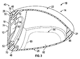
図3及び図4の各々は、垂直な前後の平面に沿って見た、互いに反対の方向を向いている概略的な断面図40,42を概略的に示す(すなわち、図3は概ねつま先を向いており、図4は概ねかかとを向いている)。図示されるように、本体14は、空気で満たされた内部空間/空洞44の少なくとも一部を取り囲み、かつ/或いは画定し得る。図3及び図4は、閉塞された空洞(すなわち、外部環境から隔てられた空洞)として空洞44を示しているが、他の実施例においては、空洞44は、例えば、クラウン22及びソール20の一方又は両方の一部を除去することにより、部分的に開放していてもよい。
Each of FIGS. 3 and 4 schematically shows a schematic
図3及び図4に示される符号40及び符号42の実施例は更に、クラウン22及びソール20の薄肉性を示すとともに、概してスカート24と呼ばれる部分を更に示している。一構成においては、スカート24は、本体14の周りにかつクラウン22とソール20との間に配置された更に厚い材料の帯46を含み、かつ/或いはこの帯46によって画定され得る。この材料の帯46は、本体14の外側縁部を衝撃に対して補強することによって構造的機能を果たすことができるが、慣性モーメントを増大させかつ/或いは重心を変えるためにスカート24全体に亘って変更されてもよい。
The embodiment of
フェイス12は、一般に金属又は金属合金から形成されており、フェイスサポート(フェイス支持体)48によって本体14上に構造的に支持され得る。フェイスサポート48は、本体14の一体化部分とすることができ、一般に衝撃時にフェイス12から荷重/応力を受けることができる。フェイスサポート48は、こうして受けた荷重/応力を本体14の残りの部分に伝達し、そこでその荷重/応力が消散及び/又は吸収され得るように機能することができる。フェイスサポート46は、フェイス12及び/又は前向き壁26の後ろでわずかに凹設されてもよく、打撃面18の反対側にあるフェイス12の背面50と接触してもよい。一構成においては、フェイスサポート48は、概してフェイス12の周縁52に近接して配置されてもよく、フェイス12の背面50が空洞44にさらされる開放中心領域54を画定してもよい。また図3に概略的に示されているように、フェイスサポート48は、フェイスがサポート48と面一で接触する前にいくらかのフェイスたわみ量が実現させるように(すなわち、制限された「トランポリンのような効果」を促進するために)、角度を付する性質を有し得る(すなわち、フェイス12の背面50がサポート48と接触することができる)。
The
金属合金で商業的に実現可能なものよりも構造上の質量を減らすために、クラブヘッド10の本体14は、ボールの衝撃によって与えられる繰り返し応力に耐えるほど大きい降伏強さを有するポリマー材料から形成することができる。そのような材料の例としては、特定のポリアミド、ポリイミド、ポリアミドイミド、ポリエーテルエーテルケトン(PEEK)、ポリカーボネート、エンジニアリングポリウレタン、及び/又は他の同様の材料を含み得る。一般に、ポリマー材料は、熱可塑性物質か熱硬化性樹脂のどちらかでよく、何ら充填されていない場合もあれば、ガラス繊維又は炭素繊維が充填されている場合もあり、或いは、強度を増大させるために他の適切な充填材及び/又は添加物をする場合もある。適切な材料が、一構成においては、少なくとも約180MPaの引張強度を有し、他の構成においては、少なくとも約220MPaの引張強度を有する。
In order to reduce the structural mass over what is commercially achievable with metal alloys, the
一構成においては、ポリマー製の本体14の全体が単一の連続片として形成され得る。このような設計は、応力が集中する点となり得る継ぎ目、溶接線、又はその他のパーティングラインを少なくすることにより、強度の利点を得ることができる。他の構成においては、本体14の設計は、ソール20内に配置された単一の継ぎ目60を含み、その後、(要求に応じて)閉塞された空洞44を形成するために、本体14にソールプレート62が接着/溶着されるとよい。しかし、上述した通り、いくつかの設計においては、開放されたキャビティ・クラブヘッド10を得るために、ソールプレート62が省略される場合もある。継ぎ目線を減らすことにより、いくつかの構造上及び製造上の利点がもたらされるが、上記の例は、例示することを意図し、2つ以上の継ぎ目を有する他の設計を除外することを意図していない。
In one configuration, the entire
フェイス12とフェイスサポート48との間に剛性の連結部を設けるために、フェイス12は、本体14の一部と連動するように構成された、フェイス12の周縁52に配置された1つ又は複数の機械的ロック特徴部70を含み得る。一構成においては、ロック特徴部は、フェイス12の背面50から延びるフランジ72を含み、本体14の製造時にフェイスサポート48に埋め込まれてもよい。例えば、本体14を形成するために使用されるポリマーは、該ポリマーがフランジ72と接触し例えばフェイス12の背面50に達するまでフランジ72を取り囲むように、フランジ72の周りにオーバーモールドされる。ポリマーが固化すると、該ポリマーは、フェイスサポート48内にしっかりとフランジを固定し、サポート48からフランジが引き抜かれることを妨げることができる。
In order to provide a rigid connection between the
剛性の連結手段を設けることに加えて、オーバーモールドされたフランジ72は、フェイス12と本体14との間で力を効率的に伝達することもできる。具体的には、フランジ72の幾何学的形状は、フェイス12と本体14との間の接触面積を増大させる(従って接触圧力を下げる)ことができる。型成形プロセスは更に、フランジ72の全表面積に亘って、該フランジ72とフェイスサポート48との間の一様な接触をもたらすことができる。このような設計は、複数の別々の点のみでしっかりと接触している固着されたフェイス・インレー(象眼)を有するクラブヘッドと比較して、力を一様に伝達することができる。
In addition to providing rigid coupling means, the
適切なフランジは様々な形状及び寸法を含み得るが、図3及び図4に示されている例は、一般に、フェイス12の背面50からこの面50に対してほぼ垂直方向に延びる第1の部分と第1の部分から半径方向外側に広がる第2の部分とを含む「L字」形の形状に形成されたフランジ72である。図5及び図6は、クラブ本体14内にフェイス12を機械的に保持するために使用され得る他のフランジ構成を概ね示す。これらの例としては、双対のフランジ設計(図5)及び半径方向内側に向いた「L」形のフランジ設計(図6)がある。他の構成においては、同様に本体14と機械的に連動するフック、タブ、角度の付されたポスト、又は他のそのような突出部を含み得る。フェイス12は一般に、フェイス12の周縁52に間隔をあけて配置された複数の別々のロック特徴部70を含み、或いは図7に示されているような周縁52の全体に延在する単一の連続的なフランジ72を含み得る。
While suitable flanges may include a variety of shapes and dimensions, the example shown in FIGS. 3 and 4 generally includes a first portion that extends generally perpendicular to the
上述した設計のすべてに共通するのは、フェイス12に対してほぼ平行な方向に延在するとともに、フェイス12からある距離だけ離間して配置されたフランジ72である。「ほぼ平行」とは、フランジ72が打撃面18に対して約±30°の範囲内で平行に延びているものとする。このような設計においては、本体14のポリマーをフランジ72とフェイス12の背面50との間に流すことにより、フェイス12が本体14から自由に抜け出てしまうことを防ぐ機械的インターロックを形成することができる。フランジ72は、フェイス12の背面50とフランジ72との間の距離に広がる延長部材を介してフェイス12の残りの部分に連結される。エッジ溶接式フェイスでは、この延長部材は、ポリマーによって完全に取り囲まれてもよい(図3〜図6に示されている)。カップ・フェイス設計では、延長部材は、クラブヘッド10の外表面を形成することができる。上記の設計に拘わらず、打撃面18、延長部材、及びフランジ72は、同様の材料構造を有することができ、かつ/或いは単一の材料から形成することができる。
Common to all of the designs described above is a
上述したように、このクラブヘッド10は、引張強度の高いポリマー材料をクラブ本体14の形状に型成形することによりつくられる一方で、ポリマー材料が金属フェイス12のいくつかの保持特徴部を確実にオーバーモールドする。図8は、現設計のクラブヘッド10を製造するために使用され得る製造方法80を概して示す。方法80は一般に、実質的に中空の本体の幾何学的形状及びフェイス・インターロックを作り出すために、「ロストコア成形」として知られる成形技法を使用することができる。ロストコア成形は、典型的には、低い融解温度(例えば約120℃〜約200℃)又は高い溶解度のいずれかを有する材料からコア型を作り、条件に適合する融解温度(又は高溶解度)を有するポリマー材料でコアをオーバーモールドし、ポリマー材料を冷却し、(熱可塑性であれば)固まらせ、続いてコアを融解つまり溶解して流出させ、従って型成形済みのポリマー部分だけが残る。このプロセスは、(本体を多数の別々の部分で形成し、それらを互いに接着/溶着しようとするのとは対照的に)継ぎ目のない単一の型成形作業時に複雑な内部の幾何学的形状が形成されることを可能にする。
As described above, the
引き続き図8を参照すると、製造方法80は、ステップ82でフェイス12をつくることから始まる。フェイス12は一般に、鋳造(例えば、インベストメント鋳造プロセスによる)又は鍛造で適切な形状にされ得る軽量の金属合金から形成することができる。適切なフェイス材料の非限定的な例としてはステンレス鋼(例えば、AISIタイプ304又はAISIタイプ630ステンレス鋼)やチタン(例えば、Ti−6Al−4Vチタン合金)などでよいが、当技術分野で知られている他の金属合金、金属アモルファス合金、及び/又は非金属材料が同様に使用されてもよい(例えば、制限なく、高強度ポリマー又は金属ポリマーのラミネート)。
With continued reference to FIG. 8, the
他のプロセスにおいては、ステップ84でクラブヘッド10の内部空洞44に概ね整合する溶融可能コアが形成され得る。図9は概して、クラブヘッド10の分解図100を示し、溶融可能コア102の一実施例が本体14の上方に示されている。そのようなコア102は、水、アセトン、又は他の周知の溶剤若しくは特別につくられた溶剤に溶解することができるポリマー材料から構成され得る。或いは、コア102は、比較的低い融解温度を有する金属合金で構成されてもよい。典型的な融解温度の低い合金の例としては、ビスマス、スズ、鉛、及び亜鉛の様々な組成物がある。コア102は、典型的な製造方法、例えば、鋳造、機械加工若しくは射出成形、又はこれらの組合せを用いて所望の形状に形成され得る。
In other processes, a meltable core that generally matches the
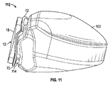
再び図8を参照すると、ステップ86で、フェイス12は、溶融可能コア又は溶融可能コア102に固着され得る。図10及び図11の各々は、コア102の前部114に固着されたフェイス12を有する溶融可能コア102の上面斜視図110及び側面図112を示す。さらに、図12及び図13は、垂直な前後の平面に沿って見た、フェイス12及びコア102の概略的な断面図116を示す。一般に、図12は、オーバーモールドする前のコア102に固着されたフェイス12を示し、図13は、適切な位置に本体14が型成形された同じアセンブリ(すなわち、中間ゴルフクラブヘッドアセンブリ)を示す。
Referring again to FIG. 8, at
図10〜図13の各々に概略的に示されているように、一実施例においては、フランジ72は、フェイス12の中心部分74から半径方向外側に延在し得る。図12及び図13に最もよく示されているように、一構成においては、コア102は、フェイス12の背面50が空洞44に晒される開放された中心領域54を形成するべき中央領域118内でのみフェイス12の背面50と接触することができる。従って、コア102は、フェイス12を支持し、繰り返しの衝撃荷重をフェイス12から本体14に伝達するために適切に寸法付けられたフェイスサポート48を設けるのに充分な量だけフランジ72から隔てられてもよい。
As shown schematically in each of FIGS. 10-13, in one embodiment, the
フェイス12は、適切な一時的なアタッチメント手段を用いてコア102に固着され得る。結局は、一時的なアタッチメントは、フェイス12及びコア102がオーバーモールドを受けるために型成形用の空洞内に配置されたときに、適切な相対位置及び位置決めを維持することを可能にする。一構成においては、このアタッチメント手段は、フェイス12からコア102内に配置された対応する位置決め穴の中にまで延びることができる複数の位置合せピン120を含み得る。図7は概して、そのような位置合せピン120がフランジ72の一部から延在し得ることを示す一実施例である。これらのピン120は、適所に鋳造される場合もあれば、他の別個のプロセスを用いてフェイス12に接合される場合もある。図12及び図13は、概して、コア102にフェイスを固着させるための位置合せピン120の使用を示す。
The
他の構成においては、同様の位置合せピンがフェイス12の打撃面18から延出し得る。位置合せピン120は、コア102内の位置決め穴の中にまで延びるのではなく、型成形用ダイ内にフェイス12を適切に配置するために使用される場合もある。本明細書の目的で、フェイス12及びコア102を型などの中間体を介して直接隣に接触して保持することは、本明細書中で使用される「固着」方法の一つである。コア上に本体14がオーバーモールドされると、位置合せピンを除去するように打撃面18が機械加工され得る。
In other configurations, similar alignment pins can extend from the
他の構成においては、フェイス12は、フェイス12がコア102に対して適切に配置されかつ方向付けられるのを確実にする1つ又は複数の位置決め特徴部、例えば一意の表面輪郭、エンボス加工部、割出し突出部、又はその他の類似の特徴部を使用してコア102上に配置することができる。再び図7を参照すると、一実施例においては、フェイスの背面50は、レリーフ状の構造補強部分122を有することができ、構造補強部分122は、局所的に増大したフェイス厚みを与えるようにフェイス12から外方に延びることができる。図9に概略的に示されているように、コア102は、フェイス12の構造補強部分122を受けるように構成された、同様の逆のレリーフ・パターン124を含み得る。オーバーモールド加工する前に、フェイス12の構造補強部分122又は他の局在的な特徴部は、コア102上の逆特徴部124と対合され得る。他の実施例においては、一時的及び/又は可溶性の粘着剤が、位置合せガイドとして使用される位置決め特徴部と共に、フェイス12をコア102に付着させるために使用され得る。
In other configurations, the
再び図8を参照すると、ステップ86でフェイス12がコア102に固着された後、ステップ88で、ポリマー製のクラブヘッド本体14がフェイス/コア・アセンブリの周囲に型成形され得る。概して、従来の型成形技法が使用され得るが、射出成形が最も直接的なプロセスである。射出成形プロセス中に、2つ以上の型成形用ダイが、型成形用空洞を形成するようにフェイス/コア・アセンブリを取り囲み得る。クラブヘッド本体14を形成するために、適切な溶融ポリマーが、型成形用ダイとコア102との間の型穴に注入され得る。この型成形プロセスの結果は、図13に概略的に示されている。概して、注入ポリマーは、さらに高い融解温度を有する場合があり、コア102の融解温度よりも高い温度で注入することができる。従って、融解(溶融)プロセス時にコアの変形及び/又は融解を防ぐために予防措置が取られる必要があり得る。そのような予防措置としては、例えば、型成形する前にコア102を予冷すること、及び/又は融解ポリマーの注入時にコア102を能動的に冷却することがある。射出成形は、フェイス/コア・アセンブリ上に本体をオーバーモールド加工する方法の一つであり、他の構成においては、様々な型成形プロセス例えば圧縮成形や浸漬被覆などが用いられ得る。
Referring again to FIG. 8, after the
再び図8を参照すると、ステップ88でクラブヘッド10の本体14がフェイス/コア・アセンブリ上にオーバーモールド加工された後、ステップ90で複合クラブヘッド10/コア・アセンブリは型成形用ダイから除去することができる。この時、アセンブリから溶融可能コア102を除去することができるのは、ステップ92で、溶融可能コア102をコア102の融解温度を超える温度で加熱して、溶融したコアがソール20内に設けられた1つ又は複数の排出ポートつまり開口部を通って空洞44から流出できるようにすることによる。コア102を除去するプロセスは、新たに形成された本体14を融解又は変形させないようにする管理されたプロセスであるとよい。コアを除去するプロセスとしては、1つ又は複数の流体浸漬槽、コアにのみ作用することができる溶剤、集中誘導加熱、オートクレーブ/オーブン加熱、又は当技術分野で周知の他のプロセスがある。或いは、いくつかの技法においては、ステップ90が省略される場合もあれば、コアを除去するプロセスがモールド内で直接行われる場合もある。
Referring again to FIG. 8, after the
図9、図12及び図13に概ね示されているように、一構成においては、コア102は、コアを除去するプロセスを加速させるために戦略的に配置され得る1つ又は複数の内部空所126を画定することができる。射出成形プロセス時にコア102から構造的に不必要な材料を除去することにより、その後に加熱されてクラブヘッド10から除去される必要のある材料の量は、もっと少ない。図13に示されているように、一構成においては、コア102内の空所126は、ソール20内の対応する開口128と一致し得る。ソール20内のこの開口128は、溶融コアが通って除去されるのに充分な排出ポートを提供することができるが、この開口128は、コア102が、型成形プロセス時に型成形用空洞内に内部で固定される/取り付けられることを可能にし得る。このような構成により、型成形用空洞内にコア102を適切に配置するために通常は要求される様々なサスペンション・ペグが不要となる。
As shown generally in FIGS. 9, 12, and 13, in one configuration, the
再び図8を参照すると、(ステップ92で)クラブヘッド10からコア102が除去された後、ステップ94で、排出ポートつまり開口128は、栓つまりソールプレート62を使用するなどして(随意に)蓋をすることができる。図13に概略的に示されているように、一構成においては、ソールプレート62を受けるために、本体14内に凹状の棚(シェルフ)部130が型成形され得る(ソールプレート62の全体が図9の分解図に示されている)。凹状の棚部130を使用することにより、ソールプレート62の外面が本体14の残りの部分の外面と面一に維持される場合があり、その場合に、ソールプレート62は、本体14に接着する、付着、溶着、溶接その他の方法で機械的に取り付けられている。
Referring again to FIG. 8, after the
上述したように、ロストコア製造技法により、ほぼ継ぎ目のないポリマー製のクラブヘッド10内に一意の幾何学的形状が内部に型成形されることを可能にすることができるが、これは、従来のクラブ製造技法では不可能であったろう。例えば、内部のリブ、ガセット及びバットレスは、このような特徴部をヘッド内に型成形するために、コア内に配置することができる。同様に、図9に概ね示されているように、コアは、スカート部分142から半径方向外側に延在する1つ又は複数の突出部140を有するように形成され得る。最終的に製造されたクラブヘッド10には、これらの突出部140は、ヘッド10の重心及び慣性モーメントを変えるために質量インサート(すなわち裁量に委ねられた質量)を受けることができる、本体14内の明確に配置された空所を形成することができる。他の実施例においては、上述した質量インサートは(突出部140の代わりに)コア102に機械的に直接に付けられる場合があり、その場合には、質量インサートは、コア102が除去されると適所に型成形され得る。一構成においては、これらのモールド・インプレース・質量は、これらの質量が本体14から抜けることを防ぐ特定の幾何学的形状つまり保持特徴部を有し得る。他の実施例においては、連続的な(しかも可変の)質量バンドがコア102のスカート部分142の周りに延在する場合もあり、その場合には、質量バンドは、コア102が除去された後、本体14内に一体に型成形され得る。いずれの場合においても、高強度ポリマーを使ってこの製造技法を用いることにより、クラブヘッドの設計及び裁量による重量配分の大きな自由度が可能となる。
As mentioned above, the lost core manufacturing technique can allow a unique geometric shape to be molded internally within the substantially seamless
本明細書は単一の空洞44を有するウッド型式のクラブに焦点を当てているが、他の実施例においては、該方法80によって多数の空洞を有するクラブヘッドを形成することもできる。例えば、一構成においては、クラブヘッド10は、周囲環境から実質的に閉塞つまり分離された第1の前方配置空洞と、「開放された」空洞であり、第1の空洞から仕切り壁で分離でもよい第2の後方配置空洞と、を含み得る。他の実施例においては、様々な空洞のサイズつまり寸法及び/又は様々な空洞仕切りの位置は、単に新しいコア設計を作ることにより容易に変えることができる。
Although this specification focuses on wood-type clubs having a
本発明を実施するための最良の形態について詳細に説明したが、当業者であれば、本発明の範囲内において本発明を実施するための様々な他の設計及び実施例があることを理解されよう。本明細書に記載されている事項のすべて及び添付の図は、図示するためのものであり、限定することを意図するものではない。 Although the best mode for carrying out the invention has been described in detail, those skilled in the art will recognize that there are various other designs and embodiments for carrying out the invention within the scope of the invention. Like. All of the matters described herein and the accompanying figures are for illustrative purposes and are not intended to be limiting.
なお、「1つの」、「少なくとも1つの」及び「1つ又は複数の」という語句は互換性があるものとして使用されており、少なくとも1つ該物品が存在することを意味する。特に明示の記載がない限り、複数のこれらの物品が存在し得る。本明細書及び特許請求の範囲において、(例えば、量や条件の)パラメータのすべての数値は、数値の前に「約」という語句が実際にあるか否かに拘わらず、すべての状況において「約」という語句によって修飾され得るものとして理解されたい。「約」という語句は、記載した数値が若干正確でないこと(正確な値に近づいていること、理論的な値に近いこと、又は近似)があっても、これを許容し得ることを示す。或いは、「約」という語句によって与えられる不正確性が当技術分野で許容されない場合にも、本明細書中における「約」との語句は、通常の測定方法及び測定のパラメータを使用することに起因する変動が生じ得ることを示す。加えて、開示された範囲には、範囲内のすべての値及び更に分割された範囲が含まれ得る。
本発明の説明において、便宜上、「ポリマー」と「樹脂」との語句は、樹脂、オリゴマー、及びポリマーを含むものとして交換可能に用いられている。「備える」、「備えている」、「含む」及び「有する」の語句は包含することを意図し、従って、記載した物品の存在を特定するが、他の物品の存在を除外することを意図していない。本明細書中で使用される「や」という語句は、1つ又は複数の列挙された種々の物品のすべての組合せを含み得る。換言すれば、「や」は、「及び/又は」を意味する。第1の、第2の、第3の、などの語句が様々な物品を互いに区別するために使用されている場合、これらの指定は単に便宜上の表示であり、物品の序列を限定するものではない。
It should be noted that the phrases “one”, “at least one” and “one or more” are used interchangeably, meaning that there is at least one such article. There may be a plurality of these articles unless specifically stated otherwise. In this specification and in the claims, all numerical values for parameters (eg, quantities and conditions) are "in all situations" regardless of whether the word "about" actually precedes the numerical value. It should be understood that it may be modified by the phrase “about”. The phrase “about” indicates that the stated numerical value may be tolerated even if it is slightly inaccurate (approaching an exact value, approaching a theoretical value, or an approximation). Alternatively, even if the inaccuracy provided by the phrase “about” is not acceptable in the art, the phrase “about” herein uses the usual measurement method and measurement parameters. It shows that the resulting variation can occur. In addition, the disclosed ranges can include all values within the ranges and further subdivided ranges.
In the description of the present invention, for convenience, the terms “polymer” and “resin” are used interchangeably as including resin, oligomer, and polymer. The phrases “comprising”, “comprising”, “including”, and “having” are intended to be included, thus identifying the presence of the article described, but excluding the presence of other articles Not done. As used herein, the phrase “ya” may include all combinations of one or more of the various listed articles. In other words, “ya” means “and / or”. Where the terms first, second, third, etc. are used to distinguish various items from each other, these designations are merely a representation for convenience and do not limit the order of the items. Absent.
Claims (20)
第1の融解温度を有する材料から上記ゴルフクラブヘッドのコアを形成するステップと、
上記コアにクラブフェイスを固着させるステップであって、第1の打撃面、第1の打撃面とは反対側の第2の面、及びロック特徴部を含む上記クラブフェイスを固着させるステップと、
第1の融解温度よりも高い第2の融解温度を有するポリマー材料から形成された本体を上記コアの周囲に型成形するステップであって、上記ロック特徴部の少なくとも一部を取り囲むように本体を上記コアの周囲に型成形するステップと、
上記本体内から上記コアを除去するステップであって、上記コアを融解させ、上記本体から溶融コアを流出させることを含む、上記コアを除去するステップと、
を含む、
ゴルフクラブヘッドを形成する方法。 In a method of forming a golf club head,
Forming the core of the golf club head from a material having a first melting temperature;
Fixing the club face to the core, the first hitting surface, the second surface opposite the first striking surface, and fixing the club face including a lock feature;
Molding a body formed of a polymeric material having a second melting temperature higher than the first melting temperature around the core, the body being surrounded by at least a portion of the locking feature; Molding around the core;
Removing the core from within the body comprising melting the core and allowing the molten core to flow out of the body; and
including,
A method of forming a golf club head.
モールド内に上記コアと上記クラブフェイスを配置し、
上記モールドと上記コアとの間にポリマー材料を射出成形すること、
を含む、請求項1に記載のゴルフクラブヘッドを形成する方法。 The step of molding the body around the core comprises:
Place the core and the club face in the mold,
Injection molding a polymer material between the mold and the core;
A method of forming a golf club head according to claim 1, comprising:
上記ロック特徴部の少なくとも一部を取り囲むように本体を上記コアの周囲に型成形するステップは、上記ポリマー材料を上記フランジの両側に流して上記本体を型成形することを含む、請求項1に記載のゴルフクラブヘッドを形成する方法。 The locking feature includes a flange extending substantially parallel to a portion of the first surface, ie, parallel to within a range of about ± 30 ° and spaced transversely from the second surface. ,
The method of claim 1, wherein the step of molding a body around the core to enclose at least a portion of the locking feature includes casting the polymer material on opposite sides of the flange to mold the body. A method of forming the described golf club head.
該ゴルフクラブヘッドを形成する方法は、上記1つ又は複数の空所の各々の中に金属のウェイトを固着させることをさらに含む、請求項1に記載のゴルフクラブヘッドを形成する方法。 Removing the core from within the body includes forming one or more cavities in the body;
The method of forming a golf club head according to claim 1, wherein the method of forming a golf club head further comprises securing a metal weight within each of the one or more cavities.
第1の融解温度を有する第1の材料から形成されたコアと、
上記コアに固着されたクラブフェイスであって、第1の打撃面、第1の打撃面とは反対側の第2の面、及び第2の面から横断方向に離間して配置されたフランジを含むクラブフェイスと、
上記コアの周囲及び上記フランジの両側に配置されたポリマー製の本体であって、第1の融解温度よりも高い第2の融解温度を有するポリマー製の本体と、
を備えるゴルフクラブヘッドアセンブリ。 In a golf club head assembly,
A core formed from a first material having a first melting temperature;
A club face fixed to the core, the first striking surface, a second surface opposite to the first striking surface, and a flange disposed transversely away from the second surface. Including club face,
A polymer body disposed around the core and on both sides of the flange, the polymer body having a second melting temperature higher than the first melting temperature;
A golf club head assembly comprising:
上記フェイスの第2の面と接触する上記コアの一部を取り囲むように、上記本体の一部が上記フェイスの第2の面と接触している、請求項7に記載のゴルフクラブヘッドアセンブリ。 A portion of the core is in contact with the second surface of the face;
8. The golf club head assembly of claim 7, wherein a portion of the body is in contact with the second surface of the face so as to surround a portion of the core that is in contact with the second surface of the face.
ステンレス鋼と、チタンを含む金属合金とのうちの少なくとも一方から形成されたクラブフェイスであって、第1の打撃面、第1の打撃面とは反対側の第2の面、及び第2の面から横断方向に離間して配置されたフランジを含むクラブフェイスと、
閉塞された空間を画定しているポリマー製の本体であって、上記クラブフェイスと該本体との間のすべての相対的平行移動を妨げるように、上記フランジの両側に配置され、該本体と上記クラブフェイスとの間の機械的干渉となるポリマー製の本体と、
を備えるゴルフクラブヘッドアセンブリ。 In a golf club head assembly,
A club face formed of at least one of stainless steel and a metal alloy containing titanium, the first striking surface, the second surface opposite to the first striking surface, and the second A club face including a flange disposed transversely away from the surface;
A polymer body defining an enclosed space, disposed on opposite sides of the flange to prevent any relative translation between the club face and the body; A polymer body that provides mechanical interference with the club face;
A golf club head assembly comprising:
Applications Claiming Priority (5)
| Application Number | Priority Date | Filing Date | Title |
|---|---|---|---|
| US201361862341P | 2013-08-05 | 2013-08-05 | |
| US61/862,341 | 2013-08-05 | ||
| US14/264,109 US9403295B2 (en) | 2013-08-05 | 2014-04-29 | Lost-core molded polymeric golf club head |
| US14/264,109 | 2014-04-29 | ||
| PCT/US2014/044504 WO2015020734A1 (en) | 2013-08-05 | 2014-06-27 | Lost-core molded polymeric golf club head |
Publications (2)
| Publication Number | Publication Date |
|---|---|
| JP2016525439A true JP2016525439A (en) | 2016-08-25 |
| JP6427190B2 JP6427190B2 (en) | 2018-11-21 |
Family
ID=52428169
Family Applications (1)
| Application Number | Title | Priority Date | Filing Date |
|---|---|---|---|
| JP2016533297A Expired - Fee Related JP6427190B2 (en) | 2013-08-05 | 2014-06-27 | Lost core molded polymer golf club head |
Country Status (5)
| Country | Link |
|---|---|
| US (1) | US9403295B2 (en) |
| EP (1) | EP3030327B1 (en) |
| JP (1) | JP6427190B2 (en) |
| CN (1) | CN105492086B (en) |
| WO (1) | WO2015020734A1 (en) |
Cited By (2)
| Publication number | Priority date | Publication date | Assignee | Title |
|---|---|---|---|---|
| JP2020044311A (en) * | 2018-09-18 | 2020-03-26 | 明安國際企業股▲分▼有限公司 | Golf club head and golf club head manufacturing method |
| KR20220120779A (en) * | 2021-02-23 | 2022-08-31 | 한국과학기술원 | Artificial Muscle Manufacturing Method through Multi-Material 3D Printer Using Co-axial Fiber Extrusion Nozzle |
Families Citing this family (19)
| Publication number | Priority date | Publication date | Assignee | Title |
|---|---|---|---|---|
| US12390698B2 (en) * | 2013-08-05 | 2025-08-19 | Karsten Manufacturing Corporation | Polymeric golf club head with metallic face |
| US9403071B2 (en) * | 2013-08-05 | 2016-08-02 | Nike, Inc. | Polymeric golf club head with metallic face |
| US10016662B1 (en) | 2014-05-21 | 2018-07-10 | Taylor Made Golf Company, Inc. | Golf club |
| US9975011B1 (en) | 2014-05-21 | 2018-05-22 | Taylor Made Golf Company, Inc. | Golf club |
| US20160271462A1 (en) * | 2015-03-17 | 2016-09-22 | Dean L. Knuth | Golf club with low and rearward center of gravity |
| US9914027B1 (en) | 2015-08-14 | 2018-03-13 | Taylor Made Golf Company, Inc. | Golf club head |
| US10183202B1 (en) | 2015-08-14 | 2019-01-22 | Taylor Made Golf Company, Inc. | Golf club head |
| US10207160B2 (en) | 2016-12-30 | 2019-02-19 | Taylor Made Golf Company, Inc. | Golf club heads |
| US20180345099A1 (en) | 2017-06-05 | 2018-12-06 | Taylor Made Golf Company, Inc. | Golf club heads |
| US10695621B2 (en) | 2017-12-28 | 2020-06-30 | Taylor Made Golf Company, Inc. | Golf club head |
| US10589155B2 (en) | 2017-12-28 | 2020-03-17 | Taylor Made Golf Company, Inc. | Golf club head |
| US10188915B1 (en) | 2017-12-28 | 2019-01-29 | Taylor Made Golf Company, Inc. | Golf club head |
| US10653927B2 (en) * | 2018-07-23 | 2020-05-19 | Acushnet Company | Multi-material golf club head |
| US11219805B2 (en) | 2018-07-23 | 2022-01-11 | Acushnet Company | Multi-material golf club head |
| US12611577B2 (en) | 2021-09-24 | 2026-04-28 | Acushnet Company | Golf club head |
| US11679313B2 (en) | 2021-09-24 | 2023-06-20 | Acushnet Company | Golf club head |
| KR102546094B1 (en) * | 2022-04-18 | 2023-07-06 | 류훈 | How to manufacture the head of the Park Golf Club |
| WO2023225134A1 (en) | 2022-05-17 | 2023-11-23 | Karsten Manufacturing Corporation | Co-molded golf club head |
| TW202541884A (en) * | 2024-03-25 | 2025-11-01 | 美商卡斯登製造公司 | Golf club head with impact response modulator |
Citations (6)
| Publication number | Priority date | Publication date | Assignee | Title |
|---|---|---|---|---|
| JPS5982873A (en) * | 1982-10-05 | 1984-05-14 | ダンロツプ・リミテツド | Head of golf club |
| JPH08501959A (en) * | 1992-09-18 | 1996-03-05 | テイラー メイド ゴルフ カムパニー,インコーポレーテッド | Method of manufacturing a golf club head by injection molding of plastic including an internal insert positioned by a fusible core |
| US6050904A (en) * | 1998-10-27 | 2000-04-18 | Kuo; Allen H. W. | Golf club head |
| JP2003339920A (en) * | 2002-05-01 | 2003-12-02 | Callaway Golf Co | Composite golf club head with metal hitting insert in front face wall |
| JP2004216131A (en) * | 2002-12-25 | 2004-08-05 | Mizuno Corp | Golf club head and golf club |
| JP2005296609A (en) * | 2004-03-19 | 2005-10-27 | Mitsubishi Rayon Co Ltd | Golf club head and manufacturing method thereof |
Family Cites Families (12)
| Publication number | Priority date | Publication date | Assignee | Title |
|---|---|---|---|---|
| US4464324A (en) | 1981-09-21 | 1984-08-07 | Ozen | Apparatus and method for injection moulding of plastic parts of irregular shape, hollow or undercut form |
| US4472092A (en) | 1982-08-09 | 1984-09-18 | Schmidt Glenn H | Fabrication of metal shell golf club heads |
| US4883623A (en) | 1986-09-08 | 1989-11-28 | Yamaha Corporation | Method for producing a golf club head |
| FR2703255A1 (en) | 1993-03-29 | 1994-10-07 | Ozen Sa | Hollow body, such as a golf club head, of molded thermoplastic material, comprising a trapped insert, and its manufacturing process. |
| JP2996455B2 (en) * | 1994-03-29 | 1999-12-27 | ダイワ精工株式会社 | Golf club head and method of manufacturing the same |
| US6340509B1 (en) | 1997-04-23 | 2002-01-22 | Radius Engineering, Inc. | Composite bicycle frame and method of construction thereof |
| CN2408920Y (en) * | 1999-12-27 | 2000-12-06 | 陈晴祺 | Golf club head with improved welding structure |
| US6508978B1 (en) | 2000-05-31 | 2003-01-21 | Callaway, Golf Company | Golf club head with weighting member and method of manufacturing the same |
| JP2002253710A (en) * | 2001-02-16 | 2002-09-10 | 井鉉 ▲チョー▼ | Golf club head |
| US6623378B2 (en) | 2001-06-11 | 2003-09-23 | Taylor Made Golf Company, Inc. | Method for manufacturing and golf club head |
| US20110236699A1 (en) | 2003-11-14 | 2011-09-29 | Tundra Composites, LLC | Work piece comprising metal polymer composite with metal insert |
| US20060240908A1 (en) | 2005-02-25 | 2006-10-26 | Adams Edwin H | Golf club head |
-
2014
- 2014-04-29 US US14/264,109 patent/US9403295B2/en not_active Expired - Fee Related
- 2014-06-27 CN CN201480044189.2A patent/CN105492086B/en not_active Expired - Fee Related
- 2014-06-27 EP EP14834313.0A patent/EP3030327B1/en not_active Not-in-force
- 2014-06-27 WO PCT/US2014/044504 patent/WO2015020734A1/en not_active Ceased
- 2014-06-27 JP JP2016533297A patent/JP6427190B2/en not_active Expired - Fee Related
Patent Citations (6)
| Publication number | Priority date | Publication date | Assignee | Title |
|---|---|---|---|---|
| JPS5982873A (en) * | 1982-10-05 | 1984-05-14 | ダンロツプ・リミテツド | Head of golf club |
| JPH08501959A (en) * | 1992-09-18 | 1996-03-05 | テイラー メイド ゴルフ カムパニー,インコーポレーテッド | Method of manufacturing a golf club head by injection molding of plastic including an internal insert positioned by a fusible core |
| US6050904A (en) * | 1998-10-27 | 2000-04-18 | Kuo; Allen H. W. | Golf club head |
| JP2003339920A (en) * | 2002-05-01 | 2003-12-02 | Callaway Golf Co | Composite golf club head with metal hitting insert in front face wall |
| JP2004216131A (en) * | 2002-12-25 | 2004-08-05 | Mizuno Corp | Golf club head and golf club |
| JP2005296609A (en) * | 2004-03-19 | 2005-10-27 | Mitsubishi Rayon Co Ltd | Golf club head and manufacturing method thereof |
Cited By (3)
| Publication number | Priority date | Publication date | Assignee | Title |
|---|---|---|---|---|
| JP2020044311A (en) * | 2018-09-18 | 2020-03-26 | 明安國際企業股▲分▼有限公司 | Golf club head and golf club head manufacturing method |
| KR20220120779A (en) * | 2021-02-23 | 2022-08-31 | 한국과학기술원 | Artificial Muscle Manufacturing Method through Multi-Material 3D Printer Using Co-axial Fiber Extrusion Nozzle |
| KR102479172B1 (en) * | 2021-02-23 | 2022-12-22 | 한국과학기술원 | Artificial Muscle Manufacturing Method through Multi-Material 3D Printer Using Co-axial Fiber Extrusion Nozzle |
Also Published As
| Publication number | Publication date |
|---|---|
| WO2015020734A1 (en) | 2015-02-12 |
| EP3030327B1 (en) | 2018-10-31 |
| US20150038259A1 (en) | 2015-02-05 |
| CN105492086B (en) | 2018-12-04 |
| EP3030327A1 (en) | 2016-06-15 |
| JP6427190B2 (en) | 2018-11-21 |
| CN105492086A (en) | 2016-04-13 |
| US9403295B2 (en) | 2016-08-02 |
| EP3030327A4 (en) | 2017-03-08 |
Similar Documents
| Publication | Publication Date | Title |
|---|---|---|
| JP2016525439A (en) | Lost core molded polymer golf club head | |
| JP6770143B2 (en) | Polymer golf club head with metal face | |
| JP6167240B2 (en) | Golf club head with polymer face | |
| US11701557B2 (en) | Golf club heads | |
| US12268940B2 (en) | Golf club head | |
| US7632195B2 (en) | Golf club head with low density crown | |
| US20240424359A1 (en) | Golf club head | |
| US20250025965A1 (en) | Laser ablation process and corresponding golf club head made by the same | |
| JP6683881B2 (en) | Golf club head with polymer hosel | |
| JP2018516125A (en) | Golf club head with molded cavity structure | |
| KR20210062041A (en) | Multi-step forging method | |
| US12390698B2 (en) | Polymeric golf club head with metallic face |
Legal Events
| Date | Code | Title | Description |
|---|---|---|---|
| A621 | Written request for application examination |
Free format text: JAPANESE INTERMEDIATE CODE: A621 Effective date: 20170626 |
|
| A977 | Report on retrieval |
Free format text: JAPANESE INTERMEDIATE CODE: A971007 Effective date: 20180516 |
|
| A131 | Notification of reasons for refusal |
Free format text: JAPANESE INTERMEDIATE CODE: A131 Effective date: 20180529 |
|
| A521 | Request for written amendment filed |
Free format text: JAPANESE INTERMEDIATE CODE: A523 Effective date: 20180824 |
|
| TRDD | Decision of grant or rejection written | ||
| A01 | Written decision to grant a patent or to grant a registration (utility model) |
Free format text: JAPANESE INTERMEDIATE CODE: A01 Effective date: 20181002 |
|
| A61 | First payment of annual fees (during grant procedure) |
Free format text: JAPANESE INTERMEDIATE CODE: A61 Effective date: 20181026 |
|
| R150 | Certificate of patent or registration of utility model |
Ref document number: 6427190 Country of ref document: JP Free format text: JAPANESE INTERMEDIATE CODE: R150 |
|
| R250 | Receipt of annual fees |
Free format text: JAPANESE INTERMEDIATE CODE: R250 |
|
| LAPS | Cancellation because of no payment of annual fees |