JP2016528811A - Multi-channel audio decoder, multi-channel audio encoder, method of using rendered audio signal, computer program and encoded audio representation - Google Patents
Multi-channel audio decoder, multi-channel audio encoder, method of using rendered audio signal, computer program and encoded audio representation Download PDFInfo
- Publication number
- JP2016528811A JP2016528811A JP2016528443A JP2016528443A JP2016528811A JP 2016528811 A JP2016528811 A JP 2016528811A JP 2016528443 A JP2016528443 A JP 2016528443A JP 2016528443 A JP2016528443 A JP 2016528443A JP 2016528811 A JP2016528811 A JP 2016528811A
- Authority
- JP
- Japan
- Prior art keywords
- audio
- rendered
- signal
- channel
- signals
- Prior art date
- Legal status (The legal status is an assumption and is not a legal conclusion. Google has not performed a legal analysis and makes no representation as to the accuracy of the status listed.)
- Granted
Links
Images


Classifications
-
- H—ELECTRICITY
- H04—ELECTRIC COMMUNICATION TECHNIQUE
- H04S—STEREOPHONIC SYSTEMS
- H04S3/00—Systems employing more than two channels, e.g. quadraphonic
-
- G—PHYSICS
- G10—MUSICAL INSTRUMENTS; ACOUSTICS
- G10L—SPEECH ANALYSIS TECHNIQUES OR SPEECH SYNTHESIS; SPEECH RECOGNITION; SPEECH OR VOICE PROCESSING TECHNIQUES; SPEECH OR AUDIO CODING OR DECODING
- G10L19/00—Speech or audio signals analysis-synthesis techniques for redundancy reduction, e.g. in vocoders; Coding or decoding of speech or audio signals, using source filter models or psychoacoustic analysis
- G10L19/008—Multichannel audio signal coding or decoding using interchannel correlation to reduce redundancy, e.g. joint-stereo, intensity-coding or matrixing
-
- H—ELECTRICITY
- H04—ELECTRIC COMMUNICATION TECHNIQUE
- H04S—STEREOPHONIC SYSTEMS
- H04S3/00—Systems employing more than two channels, e.g. quadraphonic
- H04S3/008—Systems employing more than two channels, e.g. quadraphonic in which the audio signals are in digital form, i.e. employing more than two discrete digital channels
-
- H—ELECTRICITY
- H04—ELECTRIC COMMUNICATION TECHNIQUE
- H04S—STEREOPHONIC SYSTEMS
- H04S3/00—Systems employing more than two channels, e.g. quadraphonic
- H04S3/02—Systems employing more than two channels, e.g. quadraphonic of the matrix type, i.e. in which input signals are combined algebraically, e.g. after having been phase shifted with respect to each other
-
- H—ELECTRICITY
- H04—ELECTRIC COMMUNICATION TECHNIQUE
- H04S—STEREOPHONIC SYSTEMS
- H04S2400/00—Details of stereophonic systems covered by H04S but not provided for in its groups
- H04S2400/03—Aspects of down-mixing multi-channel audio to configurations with lower numbers of playback channels, e.g. 7.1 -> 5.1
-
- H—ELECTRICITY
- H04—ELECTRIC COMMUNICATION TECHNIQUE
- H04S—STEREOPHONIC SYSTEMS
- H04S2400/00—Details of stereophonic systems covered by H04S but not provided for in its groups
- H04S2400/11—Positioning of individual sound objects, e.g. moving airplane, within a sound field
-
- H—ELECTRICITY
- H04—ELECTRIC COMMUNICATION TECHNIQUE
- H04S—STEREOPHONIC SYSTEMS
- H04S2420/00—Techniques used stereophonic systems covered by H04S but not provided for in its groups
- H04S2420/03—Application of parametric coding in stereophonic audio systems
Landscapes
- Engineering & Computer Science (AREA)
- Physics & Mathematics (AREA)
- Acoustics & Sound (AREA)
- Signal Processing (AREA)
- Multimedia (AREA)
- Mathematical Physics (AREA)
- Audiology, Speech & Language Pathology (AREA)
- Human Computer Interaction (AREA)
- Computational Linguistics (AREA)
- Health & Medical Sciences (AREA)
- Algebra (AREA)
- General Physics & Mathematics (AREA)
- Mathematical Analysis (AREA)
- Mathematical Optimization (AREA)
- Pure & Applied Mathematics (AREA)
- Theoretical Computer Science (AREA)
- Stereophonic System (AREA)
Abstract
符号化表現に基づいて少なくとも2つの出力オーディオ信号を供給するためのマルチチャネル・オーディオ・デコーダは、複数のレンダリングされたオーディオ信号を得るために、1つ以上のレンダリング・パラメータに基づいて、符号化表現に基づいて得られた複数の復号化オーディオ信号をレンダリングするように構成される。マルチチャネル・オーディオ・デコーダは、前記レンダリングされたオーディオ信号から1つ以上の非相関化オーディオ信号を導出するように構成され、出力オーディオ信号を得るために、レンダリングされたオーディオ信号またはそのスケール化バージョンと1つ以上の非相関化オーディオ信号とを結合するように構成される。マルチチャネル・オーディオ・エンコーダは、オーディオ・デコーダを制御するための非相関化方法パラメータを供給する。【選択図】図1A multi-channel audio decoder for providing at least two output audio signals based on an encoded representation is encoded based on one or more rendering parameters to obtain a plurality of rendered audio signals A plurality of decoded audio signals obtained based on the representation are configured to be rendered. A multi-channel audio decoder is configured to derive one or more uncorrelated audio signals from the rendered audio signal and to obtain an output audio signal, the rendered audio signal or a scaled version thereof And one or more decorrelated audio signals. The multi-channel audio encoder provides decorrelation method parameters for controlling the audio decoder. [Selection] Figure 1
Description
本発明による実施の形態は、符号化表現に基づいて、少なくとも2つの出力オーディオ信号を供給するためのマルチチャネル・オーディオ・デコーダに関する。 Embodiments according to the invention relate to a multi-channel audio decoder for providing at least two output audio signals based on a coded representation.
本発明による更なる実施の形態は、少なくとも2つの入力オーディオ信号に基づいて、符号化表現を供給するためのマルチチャネル・オーディオ・エンコーダに関する。 A further embodiment according to the invention relates to a multi-channel audio encoder for providing a coded representation based on at least two input audio signals.
本発明による更なる実施の形態は、符号化表現に基づいて、少なくとも2つの出力オーディオ信号を供給するための方法に関する。 A further embodiment according to the invention relates to a method for providing at least two output audio signals based on an encoded representation.
本発明による更なる実施の形態は、少なくとも2つの入力オーディオ信号に基づいて、符号化表現を供給するための方法に関する。 A further embodiment according to the invention relates to a method for providing an encoded representation based on at least two input audio signals.
本発明による更なる実施の形態は、前記方法のうちの1つを実行するためのコンピュータ・プログラムに関する。 A further embodiment according to the invention relates to a computer program for performing one of the methods.
本発明による更なる実施の形態は、符号化オーディオ表現に関する。 A further embodiment according to the invention relates to an encoded audio representation.
一般的に言って、本発明による実施の形態は、マルチチャネル・ダウンミックス/アップミックスパラメトリックオーディオ・オブジェクト符号化システムのための非相関化コンセプトに関する。 Generally speaking, embodiments according to the present invention relate to decorrelation concepts for multi-channel downmix / upmix parametric audio object coding systems.
近年、オーディオ・コンテンツの記憶および送信の需要は、着実に増加した。さらに、オーディオ・コンテンツの記憶および送信のための良質な要件も、着実に増加した。従って、オーディオ・コンテンツの符号化および復号化のためのコンセプトは、強化されている。 In recent years, the demand for storage and transmission of audio content has steadily increased. In addition, the quality requirements for storing and transmitting audio content have steadily increased. Thus, the concept for encoding and decoding audio content has been enhanced.
例えば、いわゆる、開発された「先進的音響符号化(Advanced Audio Coding(AAC))」は、国際標準ISO/IEC 13818−7:2003において記述されている。さらに、例えば、国際標準ISO/IEC 23003−1:2007において、例えば、記述された、いわゆる「MPEGサラウンド」のように、いくつかの空間的な拡張が作成された。さらに、オーディオ信号の空間的な情報の符号化および復号化のためのさらなる改良が、いわゆる「空間オーディオ・オブジェクト符号化(Spatial Audio Object Coding)」に関する国際標準ISO/IEC 23003−2:2010において記述される。 For example, the so-called developed “Advanced Audio Coding (AAC)” is described in the international standard ISO / IEC 13818-7: 2003. In addition, several spatial extensions have been created, for example, in the international standard ISO / IEC 2303-1: 2007, as described for example in the so-called “MPEG Surround”. Furthermore, further improvements for the encoding and decoding of spatial information in audio signals are described in the international standard ISO / IEC 23003-2: 2010 for so-called “Spatial Audio Object Coding”. Is done.
さらに、良好な符号化効率を有する一般のオーディオ信号およびスピーチ信号の両方の符号化して、マルチチャネル・オーディオ信号を扱うという可能性を提供する切り替え可能なオーディオ符号化/復号化のコンセプトは、いわゆる「統一のスピーチおよびオーディオ符号化(Unified Speech and Audio Object Coding)」に関する国際標準ISO/IEC23003−3:2012において記述される。 Furthermore, a switchable audio encoding / decoding concept that offers the possibility of encoding both general audio signals and speech signals with good encoding efficiency and handling multi-channel audio signals is the so-called It is described in the international standard ISO / IEC 23003-3: 2012 on “Unified Speech and Audio Object Coding”.
さらに、更なる従来の概念が、本記述の最後において言及される参考文献において記述される。 Furthermore, further conventional concepts are described in the references mentioned at the end of this description.
しかしながら、3次元オーディオ場面の効果的な符号化および復号化のためのさらなる進歩的な概念を提供することが切望されている。 However, it is anxious to provide further progressive concepts for effective encoding and decoding of 3D audio scenes.
本発明による実施の形態は、符号化表現に基づいて少なくとも2つの出力オーディオ信号を供給するためのマルチチャネル・オーディオ・デコーダをもたらす。マルチチャネル・オーディオ・デコーダは、複数のレンダリングされたオーディオ信号を得るために、1つ以上のレンダリング・パラメータに基づいて、符号化表現に基づいて得られた複数の復号化オーディオ信号をレンダリングするように構成される。マルチチャネル・オーディオ・デコーダは、レンダリングされたオーディオ信号から1つ以上の非相関化オーディオ信号を導出するように構成される。さらに、マルチチャネル・オーディオ・デコーダは、出力オーディオ信号を得るために、レンダリングされたオーディオ信号またはそのスケール化バージョンと1つ以上の非相関化オーディオ信号を結合するように構成される。 Embodiments in accordance with the present invention provide a multi-channel audio decoder for providing at least two output audio signals based on a coded representation. The multi-channel audio decoder is configured to render a plurality of decoded audio signals obtained based on the encoded representation based on one or more rendering parameters to obtain a plurality of rendered audio signals. Configured. The multi-channel audio decoder is configured to derive one or more decorrelated audio signals from the rendered audio signal. Further, the multi-channel audio decoder is configured to combine the rendered audio signal or a scaled version thereof and one or more decorrelated audio signals to obtain an output audio signal.
本発明による実施の形態は、オーディオ品質が、複数の復号化オーディオ信号に基づいて得られるレンダリングされたオーディオ信号から1つ以上の非相関化オーディオ信号を導出することによって、および、出力オーディオ信号を得るために、レンダリングされたオーディオ信号またはそのスケール化バージョンと1つ以上の非相関化オーディオ信号とを結合することによって、マルチチャネル・オーディオ・デコーダにおいて改良されうるという知見に基づく。レンダリングの前、またはレンダリングの間に追加の非相関化信号と比較した場合、レンダリングの後、追加の非相関化信号によって出力オーディオ信号の相関特性または共分散特性を調整することがより効率的であることが分かっている。非相関化が、レンダリングの前またはレンダリングの間に実行された場合、より非相関器が必要とされるので、レンダリングされたオーディオ信号よりもレンダリングに入力される復号化オーディオ信号がある一般のケースにおいて、このコンセプトはより効率的であることが分かっている。さらに、レンダリングは、典型的には、復号化オーディオ信号の結合をもたらすので、非相関化信号は、レンダリングの前に復号化オーディオ信号を追加する場合に、アーティファクトが供給されることが分かっている。従って、本発明の本実施の形態による概念は、非相関化信号が、レンダリングの前に追加されるという点で、従来のアプローチより優れている。例えば、レンダリングされた信号の所望の相関特性または共分散特性を直接的に推定し、実際にレンダリングされた信号に非相関化オーディオ信号の供給を適応させることが可能である。そして、それは、効率とオーディオ品質との間のより良好なトレードオフを結果として得て、同時に、しばしば増加した効率およびより良好な品質を結果として得る。 Embodiments in accordance with the present invention provide that audio quality is derived by deriving one or more decorrelated audio signals from a rendered audio signal obtained based on a plurality of decoded audio signals, and the output audio signal In order to obtain, it is based on the finding that it can be improved in a multi-channel audio decoder by combining the rendered audio signal or a scaled version thereof and one or more decorrelated audio signals. It is more efficient to adjust the correlation or covariance characteristics of the output audio signal with the additional decorrelation signal after rendering when compared to the additional decorrelation signal before rendering or during rendering. I know that there is. The general case where there is a decoded audio signal that is input to the rendering rather than the rendered audio signal because if decorrelation is performed before or during rendering, more decorrelator is needed This concept has proven to be more efficient. Furthermore, since rendering typically results in a combination of decoded audio signals, a decorrelated signal has been found to provide artifacts when adding a decoded audio signal prior to rendering. . Thus, the concept according to this embodiment of the invention is superior to conventional approaches in that the decorrelated signal is added before rendering. For example, it is possible to directly estimate the desired correlation or covariance characteristics of the rendered signal and to adapt the supply of the decorrelated audio signal to the actually rendered signal. And it results in a better trade-off between efficiency and audio quality, and at the same time often results in increased efficiency and better quality.
好ましい実施の形態において、マルチチャネル・オーディオ・デコーダは、パラメトリック再構成を使用して複数のレンダリングされたオーディオ信号を得るためにレンダリングされる復号化オーディオ信号を得るように構成される。本発明による概念は、オーディオ信号のパラメトリック再構成と結合して効果をもたらすことが分かっており、ここで、例えば、パラメトリック再構成は、オブジェクト信号を記述しているサイド情報および/またはオブジェクト信号の間の関係に基づいている(オブジェクト信号は、復号化オーディオ信号を構成しうる。)。例えば、この種のコンセプトにおける比較的かなりの数のオブジェクト信号(復号化オーディオ信号)があり、レンダリングされたオーディオ信号に基づいて非相関化のアプリケーションが特に効率的であり、この種のシナリオにおいて、アーティファクトを回避することが分かっている。 In a preferred embodiment, the multi-channel audio decoder is configured to obtain a decoded audio signal that is rendered to obtain a plurality of rendered audio signals using parametric reconstruction. The concept according to the invention has been found to be effective in combination with parametric reconstruction of audio signals, where, for example, parametric reconstruction comprises side information describing object signals and / or of object signals. (The object signal may constitute a decoded audio signal). For example, there are a relatively large number of object signals (decoded audio signals) in this type of concept, and decorrelation applications are particularly efficient based on rendered audio signals, and in this type of scenario, It is known to avoid artifacts.
好ましい実施の形態において、復号化オーディオ信号は、再構成オブジェクト信号(例えば、パラメータ的に再構成されたオブジェクト信号)であり、そして、マルチチャネル・オーディオ・デコーダは、サイド情報を使用して1つ以上のダウンミックス信号から再構成オブジェクト信号を導出するように構成される。従って、レンダリングされたオーディオ信号または出力オーディオ信号の数よりも多い比較的かなりの数の再構成オブジェクト信号がある場合であっても、レンダリングされたオーディオ信号に基づくレンダリングされたオーディオ信号と1つ以上の非相関化オーディオ信号との結合は、出力オーディオ信号における相関特性または共分散特性の効果的な再構成を許容する。 In a preferred embodiment, the decoded audio signal is a reconstructed object signal (eg, a parametrically reconstructed object signal) and the multi-channel audio decoder uses one of the side information. The reconstructed object signal is derived from the above downmix signal. Thus, even if there is a relatively significant number of reconstructed object signals that are greater than the number of rendered or output audio signals, one or more rendered audio signals based on the rendered audio signal The combination with the uncorrelated audio signal allows an effective reconstruction of the correlation or covariance characteristics in the output audio signal.
好ましい実施の形態において、マルチチャネル・オーディオ・デコーダは、サイド情報からアンミキシング係数を導出し、アンミキシング係数を使用して1つ以上のダウンミックス信号から(パラメータ的に)再構成オブジェクト信号を導出するために、アンミキシング係数を適用するように構成される。従って、レンダリングのための入力信号は、オブジェクトに関連したサイド情報(例えば、オブジェクト間の相関情報またはオブジェクト・レベル差情報のように、その結果が、絶対のエネルギーを使用することによって得られる)であるサイド情報から導出される。 In a preferred embodiment, the multi-channel audio decoder derives unmixing coefficients from the side information and uses the unmixing coefficients to derive (parametrically) reconstructed object signals from one or more downmix signals. In order to do so, it is configured to apply an unmixing factor. Thus, the input signal for rendering is side information related to the object (eg, the result is obtained by using absolute energy, such as correlation information between objects or object level difference information). Derived from some side information.
好ましい実施の形態において、出力オーディオ信号の所望の相関特性または共分散特性を少なくとも部分的に獲得するために、レンダリングされたオーディオ信号と1つ以上の非相関化オーディオ信号とを結合するように構成されうる。レンダリングされたオーディオ信号から導出される、レンダリングされたオーディオ信号と1つ以上の非相関化オーディオ信号との結合は、所望の相関特性または共分散特性の調整(または再構成)を許容することが分かっている。さらに、聴覚器官印象に対して、出力オーディオ信号における適当な相関特性または共分散特性を有することが重要であり、そして、これが非相関化オーディオ信号を使用してレンダリングされたオーディオ信号を修正することによって最も達成されうることが分かっている。例えば、レンダリングされたオーディオ信号とレンダリングされたオーディオ信号に基づく非相関化オーディオ信号とを結合する場合、以前の処理ステージにおいて生じる如何なる低下も考慮されうる。 In preferred embodiments, configured to combine the rendered audio signal and one or more uncorrelated audio signals to at least partially obtain a desired correlation or covariance characteristic of the output audio signal. Can be done. The combination of the rendered audio signal and one or more decorrelated audio signals derived from the rendered audio signal may allow adjustment (or reconstruction) of the desired correlation or covariance characteristics. I know. Furthermore, it is important for auditory organ impressions to have appropriate correlation or covariance characteristics in the output audio signal, and this modifies the rendered audio signal using the decorrelated audio signal It has been found that can be achieved most by For example, when combining a rendered audio signal and a decorrelated audio signal based on the rendered audio signal, any degradation that occurs in previous processing stages may be considered.
好ましい実施の形態において、マルチチャネル・オーディオ・デコーダは、複数のレンダリングされたオーディオ信号を得るためにレンダリングされる復号化オーディオ信号のパラメトリック再構成の間におけるエネルギー損失を少なくとも部分的に補償するために、レンダリングされたオーディオ信号と1つ以上の非相関化オーディオ信号とを結合するように構成される。非相関化オーディオ信号のポストレンダリングアプリケーションは、例えば、復号化オーディオ信号のパラメトリック再構成によってレンダリング前の処理によって生じる信号欠損を修正することを許容することが分かっている。従って、それは高い精度を伴って、レンダリングに入力される復号化オーディオ信号の相関特性または共分散特性を再構成する必要がない。これは、復号化オーディオ信号の再構成を単純化し、そして、したがって、高効率をもたらす。 In a preferred embodiment, the multi-channel audio decoder is for at least partially compensating for energy loss during parametric reconstruction of the decoded audio signal that is rendered to obtain a plurality of rendered audio signals. , Configured to combine the rendered audio signal and one or more decorrelated audio signals. It has been found that post-rendering applications of decorrelated audio signals allow to correct for signal loss caused by pre-rendering processing, for example by parametric reconstruction of the decoded audio signal. Thus, it is not necessary to reconstruct the correlation or covariance characteristics of the decoded audio signal input to the rendering with high accuracy. This simplifies the reconstruction of the decoded audio signal and thus results in high efficiency.
好ましい実施の形態において、マルチチャネル・オーディオ・デコーダは、出力オーディオ信号の所望の相関特性または共分散特性を決定するように構成される。さらに、マルチチャネル・オーディオ・デコーダは、得られた出力オーディオ信号の相関特性または共分散特性が所望の相関特性または共分散特性に近似するか、または等しいように、出力オーディオ信号を得るために、レンダリングされたオーディオ信号と1つ以上の非相関化オーディオ信号とを結合を調整するように構成される。レンダリングされたオーディオ信号と非相関化オーディオ信号との結合の後に到達される出力オーディオ信号の所望の相関特性または共分散特性を算出(または決定)することによって、次々に比較的正確な再構成を許容する、処理の遅いステージで相関特性または共分散特性を調整することは可能である。従って、出力オーディオ信号の空間的な聴取印象は、所望の聴取印象によく適応される。 In a preferred embodiment, the multi-channel audio decoder is configured to determine a desired correlation characteristic or covariance characteristic of the output audio signal. In addition, the multi-channel audio decoder may obtain an output audio signal such that a correlation characteristic or covariance characteristic of the resulting output audio signal approximates or is equal to a desired correlation characteristic or covariance characteristic. The rendered audio signal and one or more decorrelated audio signals are configured to adjust the combination. By calculating (or determining) the desired correlation or covariance characteristics of the output audio signal that is reached after the combination of the rendered audio signal and the decorrelated audio signal, one after another, a relatively accurate reconstruction It is possible to adjust the correlation or covariance characteristics at an acceptable, slower stage of processing. Therefore, the spatial listening impression of the output audio signal is well adapted to the desired listening impression.
好ましい実施の形態において、複数のレンダリングされたオーディオ信号を得るために、符号化表現に基づいて得られる複数の復号化オーディオ信号のレンダリングを記述しているレンダリング情報に基づいて、所望の相関特性または所望の共分散特性を決定するように構成される。所望の相関特性または所望の共分散特性の決定におけるレンダリング処理を考慮することによって、レンダリングされたオーディオ信号と1つ以上の非相関化オーディオ信号との結合を調整するための正確な情報を獲得することは可能である。そして、それは、所望の聴取印象にマッチする出力オーディオ信号を有する可能性をもたらす。 In a preferred embodiment, to obtain a plurality of rendered audio signals, based on rendering information describing the rendering of a plurality of decoded audio signals obtained based on an encoded representation, a desired correlation characteristic or It is configured to determine a desired covariance characteristic. Obtaining accurate information for adjusting the combination of the rendered audio signal and one or more decorrelated audio signals by taking into account the rendering process in determining the desired correlation characteristics or desired covariance characteristics It is possible. It then gives the possibility to have an output audio signal that matches the desired listening impression.
好ましい実施の形態において、マルチチャネル・オーディオ・デコーダは、複数のオーディオ・オブジェクトの特性および/または複数のオーディオ・オブジェクトの間の関係を記載しているオブジェクト相関情報またはオブジェクト共分散情報に基づいて、所望の相関特性または所望の共分散特性を決定するように構成される。従って、処理の後、すなわち、レンダリングの後、オーディオ・オブジェクトに適応される相関特性または共分散特性を復元することが可能である。従って、オーディオ・オブジェクトを復号化するための複雑さが低減される。さらに、レンダリングの後のオーディオ・オブジェクトの相関特性または共分散特性を考慮することによって、レンダリングの有害な影響が回避されえ、相関特性または共分散特性は、良好な精度で再構成される。 In a preferred embodiment, the multi-channel audio decoder is based on object correlation information or object covariance information describing characteristics of multiple audio objects and / or relationships between multiple audio objects, It is configured to determine a desired correlation characteristic or a desired covariance characteristic. Thus, after processing, i.e. after rendering, it is possible to restore the correlation or covariance characteristics adapted to the audio object. Thus, the complexity for decoding audio objects is reduced. Furthermore, by taking into account the correlation or covariance characteristics of the audio object after rendering, the detrimental effects of rendering can be avoided, and the correlation or covariance characteristics are reconstructed with good accuracy.
好ましい実施の形態において、マルチチャネル・オーディオ・デコーダは、符号化表現に含まれるサイド情報に基づいて、オブジェクト相関情報またはオブジェクト共分散情報を決定するように構成される。従って、コンセプトは、サイド情報を使用する空間的なオーディオ・オブジェクト符号化アプローチに良好に適している。 In a preferred embodiment, the multi-channel audio decoder is configured to determine object correlation information or object covariance information based on side information included in the encoded representation. The concept is therefore well suited for a spatial audio object coding approach that uses side information.
好ましい実施の形態において、マルチチャネル・オーディオ・デコーダは、レンダリングされたオーディオ信号の現実の相関特性または共分散特性に基づいて、出力オーディオ信号を得るために、レンダリングされたオーディオ信号の現実の相関特性または共分散特性を決定し、レンダリングされたオーディオ信号と1つ以上の非相関化オーディオ信号との結合を調整するように構成される。従って、オーディオ・オブジェクトを再構成するか、またはレンダリングによって欠損が生じた場合、例えば、エネルギー損失のような初期の処理ステージにおいて欠損が渡されうる。このように、現実のレンダリングされたオーディオ信号と非相関化オーディオ信号との結合が所望の特性を結果として得られるように、レンダリングされたオーディオ信号と1つ以上の非相関化オーディオ信号との結合は、ニーズに非常に正確な方法で調整されうる。 In a preferred embodiment, the multi-channel audio decoder is configured to obtain a real audio correlation characteristic of the rendered audio signal to obtain an output audio signal based on the real correlation characteristic or covariance characteristic of the rendered audio signal. Or, it is configured to determine a covariance characteristic and adjust a combination of the rendered audio signal and one or more decorrelated audio signals. Thus, if a defect is caused by reconstructing an audio object or rendering, the defect may be passed in an early processing stage, for example, energy loss. Thus, combining the rendered audio signal and one or more decorrelated audio signals such that the combination of the actual rendered audio signal and the decorrelated audio signal results in a desired characteristic. Can be tailored to the needs in a very accurate manner.
好ましい実施の形態において、マルチチャネル・オーディオ・デコーダは、レンダリングされたオーディオ信号と1つ以上の非相関化オーディオ信号とを結合するように構成され、ここで、レンダリングされたオーディオ信号は、第1の混合行列Pを使用して重み付けされ、1つ以上の非相関化オーディオ信号は、第2の混合行列Mを使用して重み付けされる。これは、レンダリングされたオーディオ信号に適用される混合行列Pによって記述され、1つ以上の非相関化オーディオ信号に適用される混合行列Mによって記述される一次結合が実行される。 In a preferred embodiment, the multi-channel audio decoder is configured to combine the rendered audio signal and one or more decorrelated audio signals, wherein the rendered audio signal is a first And the one or more decorrelated audio signals are weighted using the second mixing matrix M. This is described by a mixing matrix P applied to the rendered audio signal, and a linear combination described by a mixing matrix M applied to one or more decorrelated audio signals is performed.
好ましい実施の形態において、得られた出力オーディオ信号の相関特性または共分散特性が所望の相関特性または所望の共分散特性と近似するかまたは等しくなるように、マルチチャネル・オーディオ・デコーダは、混合行列Pおよび混合行列Mの少なくとも1つを調整するように構成される。このように、適度な効率および良好な結果を典型的に可能である1つ以上の混合行列を調整する方法がある。 In a preferred embodiment, the multi-channel audio decoder is a mixing matrix such that the correlation characteristic or covariance characteristic of the resulting output audio signal approximates or is equal to the desired correlation characteristic or the desired covariance characteristic. It is configured to adjust at least one of P and the mixing matrix M. Thus, there are ways to adjust one or more mixing matrices that are typically possible with moderate efficiency and good results.
好ましい実施の形態において、マルチチャネル・オーディオ・デコーダは、混合行列Pおよび混合行列Mを一緒に算出するように構成される。従って、得られた出力オーディオ信号の相関特性または共分散特性が所望の相関特性または所望の共分散特性と近似するかまたは等しくなりうるように混合行列を得ることができる。さらに、混合行列Pおよび混合行列Mを一緒に算出した場合、混合行列Pと混合行列Mを前提条件に適合されることが可能であるように、いくつかの自由度は典型的に利用できる。 In a preferred embodiment, the multi-channel audio decoder is configured to calculate the mixing matrix P and the mixing matrix M together. Accordingly, the mixing matrix can be obtained so that the correlation characteristic or covariance characteristic of the obtained output audio signal can be approximated or equal to the desired correlation characteristic or the desired covariance characteristic. Further, when the mixing matrix P and the mixing matrix M are calculated together, several degrees of freedom are typically available so that the mixing matrix P and the mixing matrix M can be adapted to the preconditions.
好ましい実施の形態において、得られた出力オーディオ信号の共分散行列が所望の共分散行列に等しくなるように、マルチチャネル・オーディオ・デコーダは、混合行列Pおよび混合行列Mを含む結合混合行列Fを得るように構成される。 In a preferred embodiment, the multi-channel audio decoder uses a combined mixing matrix F including a mixing matrix P and a mixing matrix M so that the covariance matrix of the resulting output audio signal is equal to the desired covariance matrix. Configured to get.
好ましい実施の形態において、結合混合行列は、以下に示される式に従って算出されうる。 In a preferred embodiment, the joint mixing matrix can be calculated according to the formula shown below.
好ましい実施の形態において、マルチチャネル・オーディオ・デコーダは、レンダリングされたオーディオ信号および非相関化オーディオ信号を記述する第1の共分散行列と、出力オーディオ信号の所望の共分散特性を記述する第2の共分散行列との特異値分解を使用して決定される行列を使用して、結合混合行列Fを決定するように構成される。この種の特異値分解を使用することが、結合混合行列を決定する数値的に効率的な解決案を構成する。 In a preferred embodiment, the multi-channel audio decoder has a first covariance matrix that describes the rendered and uncorrelated audio signals and a second that describes the desired covariance characteristics of the output audio signal. The combined mixing matrix F is configured to be determined using a matrix determined using singular value decomposition with a covariance matrix of. Using this kind of singular value decomposition constitutes a numerically efficient solution for determining the joint mixing matrix.
好ましい実施の形態において、マルチチャネル・オーディオ・デコーダは、単位行列またはその倍数である混合行列Pを設定し、混合行列Mを算出するように構成される。これは、所望の空間印象を保存するのを助ける異なるレンダリングされたオーディオ信号の混合を回避する。さらに、自由度の数が低減される。 In a preferred embodiment, the multi-channel audio decoder is configured to set a mixing matrix P that is a unit matrix or a multiple thereof and calculate the mixing matrix M. This avoids mixing of different rendered audio signals that help preserve the desired spatial impression. Furthermore, the number of degrees of freedom is reduced.
好ましい実施の形態において、所望の共分散行列とレンダリングされたオーディオ信号の共分散行列との間の差が、混合行列Mを混合した後、1つ以上の非相関化信号の共分散と近似するかまたは等しくなるように、マルチチャネル・オーディオ・デコーダは、混合行列Mを決定するように構成される。このように、混合行列Mを得るための計算的にシンプルなコンセプトが与えられる。 In a preferred embodiment, the difference between the desired covariance matrix and the covariance matrix of the rendered audio signal approximates the covariance of one or more decorrelated signals after mixing the mixing matrix M. The multi-channel audio decoder is configured to determine a mixing matrix M. Thus, a computationally simple concept for obtaining the mixing matrix M is given.
好ましい実施の形態において、マルチチャネル・オーディオ・デコーダは、所望の共分散行列とレンダリングされたオーディオ信号の共分散行列との差と、1つ以上の非相関化信号の共分散行列との特異値分解を使用して決定される行列を使用して混合行列Mを決定するように構成される。これは、混合行列Mを決定するために計算的に非常に効率的な方法である。 In a preferred embodiment, the multi-channel audio decoder has a singular value of the difference between the desired covariance matrix and the covariance matrix of the rendered audio signal and the covariance matrix of one or more decorrelated signals. A mixing matrix M is configured to be determined using a matrix determined using decomposition. This is a computationally very efficient way to determine the mixing matrix M.
好ましい実施の形態において、所与のレンダリングされたオーディオ信号は、所与のレンダリングされたオーディオ信号自身の非相関化バージョンを混合されるだけの制約のもと、マルチチャネル・オーディオ・デコーダは、混合行列P,Mを決定するように構成される。このコンセプトは、小さい改善(例えば、不完全な非相関化がある場合)に制限し、または相互相関特性もしくは相互共分散特性(例えば、理想的な非相関化がある場合)を防ぎ、そして、従って、認められたオブジェクトポジションの変化を回避するために、場合によっては、価値がある。しかしながら、非理想的な非相関化がある場合には、自己相関値(または自己共分散値)が明確に修正され、そして、交差項における変化は無視される。 In the preferred embodiment, a multi-channel audio decoder is a mixed channel, with the constraint that a given rendered audio signal is only mixed with a decorrelated version of the given rendered audio signal itself. It is configured to determine the matrices P and M. This concept limits to small improvements (eg when there is incomplete decorrelation) or prevents cross-correlation or cross-covariance characteristics (eg when there is ideal decorrelation), and Therefore, in some cases it is valuable to avoid perceived object position changes. However, if there is non-ideal decorrelation, the autocorrelation value (or autocovariance value) is clearly modified and changes in the cross term are ignored.
好ましい実施の形態において、相互相関特性または相互共分散特性が小さい値(例えば、不完全な非相関化がある場合)によって変更されないままかまたは修正されるとともに、レンダリングされたオーディオ信号の自己相関値または自己共分散値のみが修正されるように、マルチチャネル・オーディオ・デコーダは、レンダリングされたオーディオ信号と1つ以上の非相関化オーディオ信号とを結合するように構成される。また、オーディオ・オブジェクトの認められた位置の劣化が回避されうる。さらに、複雑な計算量が低減されうる。しかしながら、例えば、自己共分散値がエネルギー(自己相関値)の修正の結果として修正される一方、相互相関値は、修正されないままである(それらは、相互共分散値の規格化されたバージョンを表わす)。 In a preferred embodiment, the autocorrelation value of the rendered audio signal while the cross-correlation property or cross-covariance property remains unchanged or modified by a small value (eg, when there is incomplete decorrelation) Or, the multi-channel audio decoder is configured to combine the rendered audio signal and one or more decorrelated audio signals so that only the autocovariance values are modified. Also, degradation of the recognized position of the audio object can be avoided. Furthermore, a complicated calculation amount can be reduced. However, for example, the autocovariance values are modified as a result of the energy (autocorrelation value) modification, while the crosscorrelation values remain unmodified (they have a normalized version of the crosscovariance value). Represent).
好ましい実施の形態において、マルチチャネル・オーディオ・デコーダは、単位行列またはその倍数である混合行列Pを設定し、Mが対角行列であるという制約のもと、混合行列Mを算出するように構成される。このように、相互相関特性または相互共分散特性の修正は、回避されうるか、または小さい値(例えば、不完全な非相関化がある場合)に制限されうる。 In a preferred embodiment, the multi-channel audio decoder is configured to set a mixing matrix P that is a unit matrix or a multiple thereof, and to calculate the mixing matrix M under the constraint that M is a diagonal matrix. Is done. In this way, modification of cross-correlation characteristics or cross-covariance characteristics can be avoided or limited to small values (eg, when there is incomplete decorrelation).
好ましい実施の形態において、マルチチャネル・オーディオ・デコーダは、出力オーディオ信号を得るために、レンダリングされたオーディオ信号と1つ以上の非相関化オーディオ信号とを結合するように構成され、ここで、対角行列Mは、1つ以上の非相関化オーディオ信号Wに適用される。この場合、出力オーディオ信号の共分散行列の対角要素が所望のエネルギーに等しいように、マルチチャネル・オーディオ・デコーダは、混合行列Mの対角要素を算出するように構成される。従って、レンダリング処理によって、および/または1つ以上のダウンミックス信号および空間サイド情報に基づくオーディオ・オブジェクトの再構成によって、得られうるエネルギー損失が、補償されうる。このように、出力オーディオ信号の適当な強度が獲得される。 In a preferred embodiment, the multi-channel audio decoder is configured to combine the rendered audio signal and one or more decorrelated audio signals to obtain an output audio signal, wherein the pair The angular matrix M is applied to one or more decorrelated audio signals W. In this case, the multi-channel audio decoder is configured to calculate the diagonal elements of the mixing matrix M so that the diagonal elements of the covariance matrix of the output audio signal are equal to the desired energy. Thus, the energy loss that can be obtained by the rendering process and / or by reconstruction of the audio object based on one or more downmix signals and spatial side information can be compensated. In this way, an appropriate strength of the output audio signal is obtained.
好ましい実施の形態において、マルチチャネル・オーディオ・デコーダは、所望の共分散行列の対角要素、レンダリングされたオーディオ信号の共分散行列の対角要素、および1つ以上の非相関化信号の共分散行列の対角要素に基づいて、混合行列Mの要素を算出するように構成されうる。混合行列Mの対角要素でない要素は、ゼロに設定され、所望の共分散行列は、レンダリング処理およびオブジェクト共分散行列に対して使用されるレンダリング行列に基づいて算出されうる。さらにまた、閾値は、信号に追加される非相関化の量を制限するために使用されうる。このコンセプトは、混合行列Mの要素の非常に計算的に効果的な決定を提供する。 In a preferred embodiment, the multi-channel audio decoder includes a diagonal element of a desired covariance matrix, a diagonal element of a covariance matrix of a rendered audio signal, and a covariance of one or more decorrelated signals. The elements of the mixing matrix M can be calculated based on the diagonal elements of the matrix. Elements that are not diagonal elements of the mixing matrix M are set to zero, and the desired covariance matrix can be calculated based on the rendering matrix used for the rendering process and the object covariance matrix. Furthermore, the threshold can be used to limit the amount of decorrelation added to the signal. This concept provides a very computationally effective determination of the elements of the mixing matrix M.
好ましい実施の形態において、レンダリングされたオーディオ信号またはそのスケール化バージョンと1つ以上の非相関化オーディオ信号とを結合するための方法を決定する場合、非相関化されたオーディオ信号の相関特性または共分散特性を考慮するように構成されうる。従って、非相関化の欠損が考慮されうる。 In a preferred embodiment, when determining a method for combining a rendered audio signal or a scaled version thereof with one or more uncorrelated audio signals, the correlation characteristics or co-factors of the uncorrelated audio signals are determined. It can be configured to take into account dispersion characteristics. Therefore, a lack of decorrelation can be considered.
好ましい実施の形態において、所与の出力オーディオ信号が、2つ以上のレンダリングされたオーディオ信号および少なくとも1つの非相関化オーディオ信号に基づいて供給されるように、マルチチャネル・オーディオ・デコーダは、レンダリングされたオーディオ信号と非相関化オーディオ信号とを混合するように構成されうる。このコンセプトを使用することによって、相互相関特性は、(聴覚器官の空間印象を劣化させうる)大量の非相関化信号を導く必要なく、能率的に調整されうる。 In a preferred embodiment, the multi-channel audio decoder is configured to render a given output audio signal based on two or more rendered audio signals and at least one decorrelated audio signal. And configured to mix the correlated audio signal and the decorrelated audio signal. By using this concept, the cross-correlation properties can be adjusted efficiently without having to introduce large amounts of decorrelated signals (which can degrade the spatial impression of the auditory organ).
好ましい実施の形態において、出力オーディオ信号を得るために、レンダリングされたオーディオ信号またはそのスケール化バージョンと1つ以上の非相関化オーディオ信号とを結合するための方法を決定することを異なる制約が適用される場合において、マルチチャネル・オーディオ・デコーダは、異なるモードの間で切り替えるように構成されうる。従って、複雑さおよび処理の特徴が、処理される信号に調整されうる。 In a preferred embodiment, different constraints apply to determine a method for combining a rendered audio signal or a scaled version thereof and one or more decorrelated audio signals to obtain an output audio signal. In that case, the multi-channel audio decoder may be configured to switch between different modes. Thus, complexity and processing characteristics can be adjusted to the signal being processed.
好ましい実施の形態において、マルチチャネル・オーディオ・デコーダは、レンダリングされたオーディオ信号またはそのスケール化バージョンと1つ以上の非相関化オーディオ信号とを結合する場合に、異なるレンダリングされたオーディオ信号の間における混合が許容される、第1のモード、レンダリングされたオーディオ信号またはそのスケール化バージョンと1つ以上の非相関化オーディオ信号とを結合する場合に、異なるレンダリングされたオーディオ信号の間における混合が許容されず、そして、出力オーディオ信号の相互相関特性または相互共分散特性を調整するために、所与の非相関化信号が、同じもしくは異なるスケール化、複数のレンダリングされたオーディオ信号、またはそのスケール化バージョンと結合されることが許容される、第2のモード、およびレンダリングされたオーディオ信号またはそのスケール化バージョンと1つ以上の非相関化オーディオ信号とを結合する場合に、異なるレンダリングされたオーディオ信号の間における混合が許容されず、そして、所与の非相関化信号が、所与の非相関化信号から導出されたレンダリングされたオーディオ信号以外のレンダリングされたオーディオ信号と結合されることが許容されない、第3のモード、の間で切り替えるために構成されうる。このように、複雑さおよび処理の特徴の両方が、現在のレンダリングされたオーディオ信号のタイプに調整されうる。オーディオ信号の空間の印象がこの種の修正によって劣化する場合、例えば、自己相関特性または自己共分散特性のみを修正し、明確に相互相関特性または相互共分散特性を修正することが有用でありうる。その一方で、にもかかわらず、出力オーディオ信号の強度を調整することは望ましい。一方、出力オーディオ信号の相互相関特性または相互共分散特性を調整することが望ましい場合がある。ここで、記載のマルチチャネル・オーディオ・デコーダは、この種の調整を許容する。ここで、第1のモードにおいて、相互相関特性または相互共分散特性を調整するために必要とされる非相関化信号の要素の量(または強度)が比較的小さいように、レンダリングされたオーディオ信号を結合することは可能である。このように、「ローカライザ可能な」信号要素は、相互相関特性または相互共分散特性を調整するために、第1のモードにおいて使用される。その一方、第2のモードにおいて、非相関化信号は、異なる聴取印象を自然にもたらす相互相関特性または相互共分散特性を調整するために使用される。従って、3つの異なるモードを提供することによって、オーディオ・デコーダは、扱っているオーディオ・コンテンツによく適応されうる。 In a preferred embodiment, the multi-channel audio decoder is between different rendered audio signals when combining the rendered audio signal or scaled version thereof with one or more uncorrelated audio signals. First mode, where mixing is allowed, mixing between different rendered audio signals is allowed when combining the rendered audio signal or scaled version thereof with one or more uncorrelated audio signals And a given decorrelated signal is scaled the same or different, multiple rendered audio signals, or scaled to adjust the cross-correlation or cross-covariance characteristics of the output audio signal To be combined with a version Allowed, second mode, and mixing between different rendered audio signals is allowed when combining the rendered audio signal or scaled version thereof with one or more decorrelated audio signals And a third mode in which the given decorrelated signal is not allowed to be combined with a rendered audio signal other than the rendered audio signal derived from the given decorrelated signal; Can be configured to switch between. In this way, both complexity and processing characteristics can be adjusted to the type of current rendered audio signal. If the spatial impression of the audio signal is degraded by this type of modification, it may be useful to modify only the autocorrelation or autocovariance characteristics, for example, and explicitly modify the crosscorrelation or crosscovariance characteristics. . On the other hand, it is nevertheless desirable to adjust the strength of the output audio signal. On the other hand, it may be desirable to adjust the cross-correlation characteristics or the mutual covariance characteristics of the output audio signal. Here, the described multi-channel audio decoder allows this kind of adjustment. Here, in the first mode, the rendered audio signal is such that the amount (or strength) of the decorrelated signal elements required to adjust the cross-correlation or cross-covariance characteristics is relatively small. Can be combined. Thus, “localizable” signal elements are used in the first mode to adjust the cross-correlation or cross-covariance characteristics. On the other hand, in the second mode, the decorrelated signal is used to adjust the cross-correlation or cross-covariance characteristics that naturally result in different listening impressions. Thus, by providing three different modes, the audio decoder can be well adapted to the audio content being handled.
好ましい実施の形態において、マルチチャネル・オーディオ・デコーダは、レンダリングされたオーディオ信号またはそのスケール化バージョンと1つ以上の非相関化オーディオ信号とを結合するための3つのモードを指し示す符号化表現のビットストリーム要素を評価し、そして、ビットストリーム要素に基づいてモードを選択するために構成される。したがって、オーディオ・エンコーダは、オーディオ・コンテンツのその情報に基づいて、適切なモードの信号を送信することができる。このように、出力オーディオ信号の最大の品質が、いかなる環境のもとでも達成されうる。 In a preferred embodiment, the multi-channel audio decoder is a coded representation bit indicating three modes for combining the rendered audio signal or scaled version thereof with one or more uncorrelated audio signals. Configured to evaluate the stream element and select a mode based on the bitstream element. Therefore, the audio encoder can transmit a signal in an appropriate mode based on the information of the audio content. In this way, maximum quality of the output audio signal can be achieved under any environment.
本発明による実施の形態は、少なくとも2つの入力オーディオ信号に基づいて符号化表現を供給するためのマルチチャネル・オーディオ・エンコーダをもたらす。マルチチャネル・オーディオ・エンコーダは、少なくとも2つの入力オーディオ信号に基づき、1つ以上のダウンミックス信号を供給するように構成される。さらに、マルチチャネル・オーディオ・エンコーダは、少なくとも2つの入力オーディオ信号の間の関係を記述している1つ以上のパラメータを供給するように構成される。さらに、マルチチャネル・オーディオ・エンコーダは、オーディオ・エンコーダのサイドで使用されるべき複数の非相関化モードのうちの非相関化モードを記述している非相関化方法パラメータを供給するように構成される。従って、マルチチャネル・オーディオ・エンコーダは、現在の符号化されるオーディオ信号のタイプに良く適応される適切な非相関化モードを使用するようにオーディオ・デコーダを制御しうる。このように、ここで記載されるマルチチャネル・オーディオ・エンコーダは、以前議論されたマルチチャネル・オーディオ・デコーダと協調するためによく適応される。 Embodiments in accordance with the present invention provide a multi-channel audio encoder for providing a coded representation based on at least two input audio signals. The multi-channel audio encoder is configured to provide one or more downmix signals based on at least two input audio signals. In addition, the multi-channel audio encoder is configured to provide one or more parameters describing a relationship between at least two input audio signals. In addition, the multi-channel audio encoder is configured to provide a decorrelation method parameter describing a decorrelation mode of the multiple decorrelation modes to be used on the audio encoder side. The Thus, the multi-channel audio encoder may control the audio decoder to use an appropriate decorrelation mode that is well adapted to the type of audio signal being encoded. Thus, the multi-channel audio encoder described herein is well adapted to cooperate with the previously discussed multi-channel audio decoder.
好ましい実施の形態において、マルチチャネル・オーディオ・エンコーダは、非相関化方法パラメータを選択的に供給し、オーディオ・デコーダの処理のための、レンダリングされたオーディオ信号またはそのスケール化バージョンと1つ以上の非相関化オーディオ信号とを結合する場合に、異なるレンダリングされたオーディオ信号の間における混合が許容される、第1のモード、レンダリングされたオーディオ信号またはそのスケール化バージョンと1つ以上の非相関化オーディオ信号とを結合する場合に、異なるレンダリングされたオーディオ信号の間における混合が許容されず、そして、出力オーディオ信号の相互相関特性または相互共分散特性を調整するために、所与の非相関化オーディオ信号が、同じもしくは異なるスケール化、複数のレンダリングされたオーディオ信号、またはそのスケール化バージョンと結合されることが許容される、第2のモード、およびレンダリングされたオーディオ信号またはそのスケール化バージョンと1つ以上の非相関化オーディオ信号とを結合する場合に、異なるレンダリングされたオーディオ信号の間における混合が許容されず、そして、所与の非相関化オーディオ信号が、所与の非相関化オーディオ信号から導出されたレンダリングされたオーディオ信号以外のレンダリングされたオーディオ信号と結合されることが許容されない、第3のモード、である以上に示す3つのモードの1つの信号を送信するように構成される。このように、マルチチャネル・オーディオ・エンコーダは、オーディオ・コンテンツに基づいて、上記において議論された3つのモードを通してマルチチャネル・オーディオ・デコーダを切り替えることができ、ここで、マルチチャネル・オーディオ・デコーダが処理するモードは、現在の符号化されたオーディオ・コンテンツのタイプにマルチチャネル・オーディオ・エンコーダによってよく適応されうる。しかしながら、いくつかの実施の形態において、オーディオ・デコーダの処理のための上記の3つのモードの1つか2つのみが使用されうる(または利用されうる。)。 In a preferred embodiment, the multi-channel audio encoder selectively supplies decorrelation method parameters to render the rendered audio signal or a scaled version thereof and one or more for processing of the audio decoder. A first mode, the rendered audio signal or a scaled version thereof, and one or more decorrelations, where mixing between different rendered audio signals is allowed when combined with a decorrelated audio signal When combined with an audio signal, no mixing between different rendered audio signals is allowed and a given decorrelation to adjust the cross-correlation or cross-covariance characteristics of the output audio signal Audio signals are scaled the same or different A second mode that is allowed to be combined with a plurality of rendered audio signals, or a scaled version thereof, and the rendered audio signal or a scaled version thereof and one or more decorrelated audio signals; Mixing between different rendered audio signals is not allowed, and a given decorrelated audio signal is derived from a given decorrelated audio signal The third mode, which is not allowed to be combined with any other rendered audio signal, is configured to transmit one signal of the above three modes. Thus, the multi-channel audio encoder can switch the multi-channel audio decoder through the three modes discussed above based on the audio content, where the multi-channel audio decoder is The mode of processing can be well adapted by the multi-channel audio encoder to the type of current encoded audio content. However, in some embodiments, only one or two of the above three modes for audio decoder processing may be used (or may be utilized).
好ましい実施の形態において、マルチチャネル・オーディオ・エンコーダは、入力オーディオ信号が比較的高い相関か比較的低い相関を含むかどうかに基づいて、非相関化方法パラメータを選択するように構成される。このように、デコーダにおいて使用される非相関化の適応は、現在の符号化されるオーディオ信号の重要な特徴に基づいてなされうる。 In a preferred embodiment, the multi-channel audio encoder is configured to select a decorrelation method parameter based on whether the input audio signal includes a relatively high correlation or a relatively low correlation. Thus, the decorrelation adaptation used in the decoder can be made based on important features of the current encoded audio signal.
好ましい実施の形態において、マルチチャネル・オーディオ・エンコーダは、入力オーディオ信号の間の相関または共分散が比較的高い場合、第1のモードまたは第2のモードを指定するための非相関化方法パラメータを選択し、入力オーディオ信号の間の相関または共分散が比較的低い場合、第3のモードを指定するための非相関化方法パラメータを選択するように構成される。従って、入力オーディオ信号の間の比較的小さい相関または共分散の場合において、相互共分散特性または相互相関特性の修正でない復号化モードが選択される。そのような信号は実質的に独立しているので、これは、相互相関または相互共分散の適応のための必要を取り除く、比較的低い相関(または共分散)を有する信号に大して効果的な選択であることが分かっている。むしろ、(比較的小さい相関または共分散を有する)実質的な独立入力オーディオ信号のための相互相関または相互共分散の調整は、典型的には、オーディオの品質を劣化させ、そして、同時に復号化の複雑さを増加させる。このように、このコンセプトは、マルチチャネル・オーディオ・エンコーダに入力される信号に、マルチチャネル・オーディオ・デコーダの合理的な適応を許容する。 In a preferred embodiment, the multi-channel audio encoder has a decorrelation method parameter for specifying the first mode or the second mode if the correlation or covariance between the input audio signals is relatively high. If selected, the correlation or covariance between the input audio signals is relatively low, and is configured to select a decorrelation method parameter for specifying the third mode. Accordingly, in the case of a relatively small correlation or covariance between input audio signals, a decoding mode is selected that is not a modification of the cross-covariance or cross-correlation characteristics. Since such signals are substantially independent, this is a much more effective choice for signals with relatively low correlation (or covariance), eliminating the need for cross-correlation or cross-covariance adaptation. I know that. Rather, cross-correlation or cross-covariance adjustments for substantially independent input audio signals (with relatively small correlation or covariance) typically degrade audio quality and decode simultaneously Increase the complexity. Thus, this concept allows a reasonable adaptation of the multi-channel audio decoder to the signal input to the multi-channel audio encoder.
本発明による実施の形態は、符号化表現に基づく少なくとも2つの出力オーディオ信号を供給するための方法をもたらす。方法は、複数のレンダリングされたオーディオ信号を得るために、1つ以上のレンダリング・パラメータに基づいて、符号化表現に基づいて得られた複数の復号化オーディオ信号をレンダリングするステップを含む。方法は、レンダリングされたオーディオ信号から1つ以上の非相関化オーディオ信号を導出するステップと、出力オーディオ信号を得るために、レンダリングされたオーディオ信号またはそのスケール化バージョンと1つ以上の非相関化オーディオ信号とを結合するステップも含む。この方法は、上記したマルチチャネル・オーディオ・デコーダと同じ考察に基づく。さらに、方法は、マルチチャネル・オーディオ・デコーダに関して上記について議論された特徴および機能のいずれかによって補充されることができる。 Embodiments according to the present invention provide a method for providing at least two output audio signals based on a coded representation. The method includes rendering a plurality of decoded audio signals obtained based on the encoded representation based on one or more rendering parameters to obtain a plurality of rendered audio signals. The method derives one or more decorrelated audio signals from the rendered audio signal, and one or more decorrelations with the rendered audio signal or a scaled version thereof to obtain an output audio signal. It also includes the step of combining with the audio signal. This method is based on the same considerations as the multi-channel audio decoder described above. Further, the method can be supplemented by any of the features and functions discussed above with respect to multi-channel audio decoders.
本発明による他の実施の形態は、少なくとも2つの入力オーディオ信号に基づく符号化表現を供給するための方法をもたらす。方法は、少なくとも2つの入力オーディオ信号に基づく1つ以上のダウンミックス信号を供給するステップと、少なくとも2つの入力オーディオ信号の間の関係を記述している1つ以上のパラメータを供給するステップと、オーディオ・デコーダのサイドで使用される複数の非相関化モードのうちの非相関化モードを記述している非相関化方法パラメータを供給するステップと、を含む。この方法は、上記したマルチチャネル・オーディオ・エンコーダと同じ考察に基づく。さらに、方法は、マルチチャネル・オーディオ・エンコーダに関して本願明細書において議論された特徴および機能のいずれかによって補充されうる。 Another embodiment according to the invention provides a method for providing an encoded representation based on at least two input audio signals. The method provides one or more downmix signals based on at least two input audio signals, and provides one or more parameters describing a relationship between the at least two input audio signals; Providing a decorrelation method parameter describing a decorrelation mode of the plurality of decorrelation modes used at the audio decoder side. This method is based on the same considerations as the multi-channel audio encoder described above. Further, the method can be supplemented by any of the features and functions discussed herein with respect to multi-channel audio encoders.
本発明による他の実施の形態は、上記の方法の1つ以上を実行するためのコンピュータ・プログラムをもたらす。 Other embodiments according to the present invention provide a computer program for performing one or more of the above methods.
本発明による他の実施の形態は、ダウンミックス信号の符号化表現と、少なくとも2つの入力オーディオ信号の間の関係を記述している1つ以上のパラメータの符号化表現と、オーディオ・デコーダのサイドで使用される複数の非相関化モードのうちの非相関化モードを記述している符号化非相関化方法パラメータを含む。この符号化オーディオ表現は、適切な非相関化モードの信号を送信することを許容し、従って、マルチチャネル・オーディオ・エンコーダおよびマルチチャネル・オーディオ・デコーダに関して記載される効果を実装するのに役立つ。 Other embodiments according to the present invention include an encoded representation of a downmix signal, an encoded representation of one or more parameters describing a relationship between at least two input audio signals, and an audio decoder side. A coded decorrelation method parameter describing a decorrelation mode among a plurality of decorrelation modes used in FIG. This encoded audio representation allows to transmit signals in the appropriate decorrelation mode and thus helps to implement the effects described with respect to multi-channel audio encoders and multi-channel audio decoders.
本発明の好ましい実施の形態は、添付の図面に関してその後述べられる。 Preferred embodiments of the invention will now be described with reference to the accompanying drawings.
1.図1によるマルチチャネル・オーディオ・デコーダ
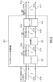
図1は、本発明の実施の形態によるマルチチャネル・オーディオ・デコーダ100のブロック概略図を示す。
1. 1 is a block schematic diagram of a
マルチチャネル・オーディオ・デコーダ100は、符号化表現110を受信して、それに基づいて、少なくとも2つの出力オーディオ信号112,114を供給するように構成される。
The
好ましくは、マルチチャネル・オーディオ・デコーダ100は、符号化表現110に基づいて復号化オーディオ信号122を供給するように構成されるデコーダ120を含む。さらに、マルチチャネル・オーディオ・デコーダ100は、複数のレンダリングされたオーディオ信号134,136を得るために、1つ以上のレンダリング・パラメータ132に基づいて、(例えば、デコーダ120によって)符号化表現110に基づいて得られる複数の復号化オーディオ信号122をレンダリングするために構成されるレンダラ130を含む。さらに、マルチチャネル・オーディオ・デコーダ100は、レンダリングされたオーディオ信号134,136から1つ以上の非相関化オーディオ信号142,144を導出するように構成される非相関器140を含む。さらに、マルチチャネル・オーディオ・デコーダ100は、出力オーディオ信号112,114を得るために、レンダリングされたオーディオ信号134,136またはそのスケール化バージョンと1つ以上の非相関化オーディオ信号142,144とを結合するように構成されるコンバイナ150を含む。
Preferably, the
しかしながら、上記の機能が与えられる限り、マルチチャネル・オーディオ・デコーダ100の異なるハードウェア構成が可能である点に留意されたい。
However, it should be noted that different hardware configurations of the
マルチチャネル・オーディオ・デコーダ100の機能に関して、非相関化オーディオ信号142,144は、レンダリングされたオーディオ信号134,136から導出され、非相関化オーディオ信号142,144は、出力オーディオ信号112,114を得るために、レンダリングされたオーディオ信号134,136と結合される点に留意されたい。レンダリングされたオーディオ信号134,136から非相関化オーディオ信号142,144を導出することによって、レンダリングされたオーディオ信号134,136の数は、典型的には、レンダラ130に入力される復号化オーディオ信号122の数から独立しているので、特に効果的な処理が達成されうる。このように、典型的には、非相関化の効果は、実施効率を改良する復号化オーディオ信号122の数から独立している。さらに、レンダリングの後の非相関化を適用することは、非相関化がレンダリングの前に適用される場合において、複数の非相関化信号を結合する場合に、レンダラによって引き起こされるアーティファクトの導入を回避する。さらに、レンダリングされたオーディオ信号の特性は、典型的には、良好な品質の出力オーディオ信号を結果として得る非相関器140によって実行される非相関化において考慮されうる。
With respect to the functionality of the
さらに、マルチチャネル・オーディオ・デコーダ100が、本願明細書において記載されている特徴および機能によって補充されうる点に留意されたい。特に、本願明細書において記載されるような個々の改良は、それによる処理の効率化および/または出力オーディオ信号の品質の改良のために、マルチチャネル・オーディオ・デコーダ100に導入されうる点に留意されたい。
Furthermore, it should be noted that the
2.図2によるマルチチャネル・オーディオ・エンコーダ
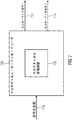
図2は、本発明の実施の形態によるマルチチャネル・オーディオ・エンコーダ200のブロック概略図を示す。マルチチャネル・オーディオ・エンコーダ200は、2つ以上の入力オーディオ信号210,212を受信し、それに基づいて符号化表現214を供給するように構成される。マルチチャネル・オーディオ・エンコーダは、少なくとも2つ以上の入力オーディオ信号210,212に基づいて、1つ以上のダウンミックス信号222を供給するように構成されるダウンミックス信号プロバイダ220を含む。さらに、マルチチャネル・オーディオ・エンコーダ200は、少なくとも2つの入力オーディオ信号210,214の間の関係(例えば、相互相関、相互共分散、レベル差等)を記述している1つ以上のパラメータ232を供給するように構成されるパラメータ・プロバイダ230を含む。
2. Multi-Channel Audio Encoder According to FIG. 2 FIG. 2 shows a block schematic diagram of a
さらに、マルチチャネル・オーディオ・エンコーダ200は、オーディオ・デコーダのサイドにおいて使用されるべき複数の非相関化モードのうちの非相関化モードを記述している非相関化方法パラメータ242を供給するように構成される非相関化方法パラメータ・プロバイダ240も含む。1つ以上のダウンミックス信号222、1つ以上のパラメータ232および非相関化方法パラメータ242は、例えば、符号化表現214に、符号化の形式で含まれる。
Further, the
しかしながら、上記のような機能が満足される限り、マルチチャネル・オーディオ・エンコーダ200のハードウェア構成は異なりうることに留意されたい。換言すれば、個々のブロック(例えば、ダウンミックス信号プロバイダ220に、パラメータ・プロバイダ230に、そして非相関化方法パラメータ・プロバイダ240に)マルチチャネル・オーディオ・エンコーダ200の機能の配分は、例として、考慮されるべきである。
However, it should be noted that the hardware configuration of the
マルチチャネル・オーディオ・エンコーダ200の機能に関して、1つ以上のダウンミックス信号222および1つ以上のパラメータ232が、例えば、SAOCマルチチャネル・オーディオ・エンコーダまたはUSACマルチチャネル・オーディオ・エンコーダにおけるような従来の方法において供給される点に留意されたい。しかしながら、マルチチャネル・オーディオ・エンコーダ200によっても供給され、そして、符号化表現214に含まれる非相関化方法パラメータ242は、入力オーディオ信号210,212にまたは所望の再生品質に非相関化モードを適用するために使用されうる。従って、非相関化モードは、オーディオ・コンテンツの異なるタイプに適用されうる。例えば、異なる非相関化モードは、入力オーディオ信号210,212が強く相関しているオーディオ・コンテンツのタイプに対して、および入力オーディオ信号210,212が独立しているオーディオ・コンテンツのタイプに対して、選択される。さらに、異なる非相関化モードは、空間印象が特に重要であるオーディオ・コンテンツのタイプに対して、および空間印象がより重要でないかまたは下位の重要性(例えば、個々のチャネルの再生と比較した場合)におけるオーディオ・コンテンツのタイプに対して、非相関化モードパラメータ242によって信号を送信されうる。従って、符号化表現214を受信するマルチチャネル・オーディオ・デコーダは、マルチチャネル・オーディオ・エンコーダ200によって制御され、復号化の複雑さと再生品質の間の最良の可能な妥協をもたらす復号化モードを設定されうる。
With respect to the functionality of the
さらに、マルチチャネル・オーディオ・エンコーダ200は、本願明細書において記載されている特徴および機能のいずれかによって補充されうる点に留意されたい。本願明細書において記載されている可能な付加的な特徴および改良は、それによって、マルチチャネル・オーディオ・エンコーダ200を改良するように(または強化するように)、個々にまたは組み合わせて、マルチチャネル・オーディオ・エンコーダ200に追加されうる点に留意されたい。
Furthermore, it should be noted that multi-channel
3.図3による少なくとも2つの出力オーディオ信号を供給するための方法
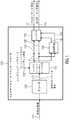
図3は、符号化表現に基づいて少なくとも2つの出力オーディオ信号を供給するための方法300のフローチャートを示す。方法は、複数のレンダリングされたオーディオ信号を得るために、1つ以上のレンダリング・パラメータに基づいて得られた複数の復号化オーディオをレンダリングするステップ310を含む。方法300は、また、レンダリングされたオーディオ信号から1つ以上の非相関化オーディオ信号を導出するステップ320を含む。方法300は、また、出力オーディオ信号332を得るために、レンダリングされたオーディオ信号またはそのスケール化バージョンと1つ以上の非相関化オーディオ信号とを結合するステップ330を含む。
3. Method for Providing At least Two Output Audio Signals According to FIG. 3 FIG. 3 shows a flowchart of a
方法300は、図1によるマルチチャネル・オーディオ・デコーダ100と同じ考察に基づく点に留意されたい。さらに、方法300は、(個々に、または組み合わせて)本願明細書において記載される特徴および機能のいずれかによって補充されうる点に留意されたい。
It should be noted that
4.図4による符号化表現を提供するための方法
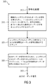
図4は、少なくとも2つの入力オーディオ信号に基づく符号化表現を供給するための方法400のフローチャートを示す。方法400は、少なくとも2つの入力オーディオ信号に基づく1つ以上のダウンミックス信号を供給するステップ410を含む。さらに、方法400は、少なくとも2つの入力オーディオ信号412の間の関係を記述している1つ以上のパラメータを供給するステップ420と、オーディオ・デコーダのサイドで使用される複数の非相関化モードのうちの非相関化モードを記述している非相関化方法パラメータを供給するステップ430とを含む。従って、好ましくは、1つ以上のダウンミックス信号の符号化表現、少なくとも2つの入力オーディオ信号の間の関係を記述している1つ以上のパラメータ、および非相関化方法パラメータを含む符号化表現432が供給される。
4). Method for Providing Coded Representation According to FIG. 4 FIG. 4 shows a flowchart of a
上記の説明も適用されるように、方法400は、マルチチャネル・オーディオ・エンコーダ200と同じ考察に基づく点に留意されたい。
It should be noted that
さらに、ステップ410,420,430の命令は、柔軟に変化することができ、これが、方法400のための実行環境において可能な限り、ステップ410,420,430も、並行して実行可能である点に留意されたい。さらに、方法400は、個々に、または組み合わせて、本願明細書において記載される特徴および機能のいずれかによって補充されうる点に留意されたい。例えば、方法400は、マルチチャネル・オーディオ・エンコーダに関して本願明細書において記載される特徴および機能のいずれかによって補充されうる。しかしながら、符号化表現432を受信する本願明細書に記載されるマルチチャネル・オーディオ・デコーダの特徴および機能に対応する特徴および機能を含むことも可能である。
Further, the instructions of
5.図5による符号化オーディオ表現
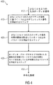
図5は、本発明の実施の形態による符号化オーディオ表現500の概略図を示す。
5. Encoded Audio Representation According to FIG. 5 FIG. 5 shows a schematic diagram of an encoded
符号化オーディオ表現500は、ダウンミックス信号の符号化表現510、少なくとも2つのオーディオ信号の間の関係を記述している1つ以上のパラメータの符号化表現520を含む。符号化オーディオ表現500は、オーディオ・デコーダのサイドで使用される複数の非相関化モードのうちの非相関化モードを記述している符号化非相関化方法パラメータ530も含む。従って、符号化オーディオ表現は、オーディオ・エンコーダからオーディオ・デコーダに非相関化モードの信号を送信することを許容する。従って、符号化オーディオ表現は、(例えば、1つ以上のダウンミックス信号の符号化表現510によって、および少なくとも2つのオーディオ信号(例えば、1つ以上のダウンミックス信号の符号化表現510にダウンミックスされている少なくとも2つのオーディオ信号))の間の関係を記述している1つ以上のパラメータの符号化表現520によって記述されるオーディオ・コンテンツの特性によく適応される非相関化モードを得ることが可能である。このように、符号化オーディオ表現500は、特に良好な聴覚器官の空間印象および/または特に、聴覚器官の空間印象と復号化の複雑さとの間の良好なトレードオフを伴う符号化オーディオ表現500によって表わされるオーディオ・コンテンツのレンダリングを許容する。
The encoded
さらに、符号化表現500が、個々に、または組み合わせて、マルチチャネル・オーディオ・エンコーダおよびマルチチャネル・オーディオ・デコーダに関して記載されている特徴および機能のいずれかによって補充されうる点に留意されたい。
Further, it should be noted that the coded
6.図6によるマルチチャネル非相関器
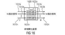
図6は、本発明の実施の形態によるマルチチャネル非相関器600のブロック概略図を示す。
6). Multi-channel decorrelator according to FIG. 6 FIG. 6 shows a block schematic diagram of a
マルチチャネル非相関器600は、N個の非相関器入力信号610a〜610nの第1のセットを受信し、それに基づいて、N’個の非相関器出力信号612a〜612n’の第2のセットを供給するように構成される。換言すると、マルチチャネル非相関器600は、非相関器入力信号610a〜610nに基づいて複数の(少なくともおよそ)非相関化信号612a〜612n’を提供するように構成される。
マルチチャネル非相関器600は、N個の非相関器入力信号610a〜610nの第1のセットをK個の非相関器入力信号622a〜622kの第2のセットにプレミックスするように構成される、プレミキサ620を含み、Kは、Nよりも小さい(KおよびNは整数である)。マルチチャネル非相関器600は、K個の非相関器入力信号622a〜622kの第2のセットに基づいてK’個の非相関器出力信号632a〜632k’の第1のセットを供給するように構成される非相関化(または非相関器の主要部)も含む。さらに、マルチチャネル非相関器は、K’個の非相関器出力信号632a〜632k’の第1のセットをN’個の非相関器出力信号612a〜612n’の第2のセットにアップミックスするように構成されるポスト・ミキサ640を含み、N’はK’より大きい(N’およびK’は整数である)。
しかしながら、マルチチャネル非相関器600の所与の構成は、例として考慮されるべきであり、本願明細書において記載されている機能が提供される限り、マルチチャネル非相関器600を機能的なブロック(例えば、プレミキサ620、非相関化もしくは非相関器の主要部630、およびポスト・ミキサ640)にさらに分割することは必要ない点に留意されたい。
However, a given configuration of
マルチチャネル非相関器600の機能に関して、現実の非相関化が、例えば、直接、N個の非相関器入力信号が適用されるコンセプトを比較したとき、N個の非相関器入力信号の第1のセットからK個の非相関器入力信号の第2のセットを導出するようにプレミックスを実行し、そして、(プレミックスされまたは「ダウンミックされた」)K個の非相関器入力信号の第2のセットに基づいて非相関化を実行するコンセプトは、複雑さの低減をもたらすことに留意されたい。さらに、N’個の非相関器出力信号の第2の(アップミックスされた)セットは、アップミキサ640によって実行されうるポストミキシングに基づいて、現実の非相関化の結果である非相関器出力信号の第1の(元の)セットに基づいて得られる。このように、マルチチャネル非相関器600は、(外側からみられたとき)効果的にN個の非相関器入力信号を受信し、そして、それに基づいて、N’個の非相関器出力信号を供給する。その一方で、現実の非相関器の主要部630は、より少ない数の信号(すなわち、K個の非相関器入力信号の第2のセットのK個のダウンミックスされた非相関器入力信号622a〜622k)のみを処理するだけである。このように、マルチチャネル非相関器600の複雑さは、従来の非相関器と比較したとき、非相関化(または非相関器の主要部)630の入力サイドでの(好ましくは、いかなる非相関化の機能のない線形のプレミキシングである)ダウンミックまたは「プレミキシング」を実行することによって、そして、非相関化(または非相関器の主要部630)の(元の)出力信号632a〜632k’に基づいて、(例えば、いかなる追加の非相関化の機能のない線形のアップミキシングである)アップミキシングまたは「ポストミキシング」を実行することによって、実質的に低減されうる。
With respect to the function of the
さらに、マルチチャネル非相関器600は、マルチチャネル非相関化に関して、またマルチチャネル・オーディオ・デコーダにも関して、本願明細書において記載される特徴および機能のいずれかによって補充されうる点に留意されたい。本願明細書において記載される特徴は、それによって、マルチチャネル非相関器600を改良するかまたは強化するように、個々に、または、組み合わせて、マルチチャネル非相関器600に追加されうる点に留意されたい。
It is further noted that
複雑さの低減のないマルチチャネル非相関器は、K=N(そして、おそらくK’=N’またはK=N=K’=N’でさえ)、に対して上記したマルチチャネル非相関器から導出されうる点に留意されたい。 A multichannel decorrelator without complexity reduction is from the multichannel decorrelator described above for K = N (and possibly K ′ = N ′ or even K = N = K ′ = N ′). Note that it can be derived.
7.図7によるマルチチャネル・オーディオ・デコーダ
図7は本発明の実施の形態によるマルチチャネル・オーディオ・デコーダ700のブロック概略図を示す。
7). Multi-Channel Audio Decoder According to FIG. 7 FIG. 7 shows a block schematic diagram of a
マルチチャネル・オーディオ・デコーダ700は、符号化表現710を受信し、それに基づいて、少なくとも2つの出力信号712,714を供給するように構成される。マルチチャネル・オーディオ・デコーダ700は、図6によるマルチチャネル非相関器600と実質的に同一であるマルチチャネル非相関器720を含む。さらに、マルチチャネル・オーディオ・デコーダ700は、従来技術において当業者により知られている、または他のマルチチャネル・オーディオ・デコーダに関して本願明細書に記載されるようなマルチチャネル・オーディオ・デコーダの特徴または機能のいずれかを含みうる。
さらに、マルチチャネル・オーディオ・デコーダ700が、高効率のマルチチャネル非相関器720を使用するので、マルチチャネル・オーディオ・デコーダ700は、従来のマルチチャネル・オーディオ・デコーダと比較した場合、特に高い効率を含む。
In addition, because multi-channel
8.図8によるマルチチャネル・オーディオ・エンコーダ
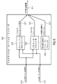
図8は、本発明の実施の形態によるマルチチャネル・オーディオ・エンコーダ800のブロック概略図を示す。マルチチャネル・オーディオ・エンコーダ800は、少なくとも2つの入力オーディオ信号810,812を受信し、それに基づいて、入力オーディオ信号810,812によって表わされるオーディオ・コンテンツの符号化表現814を供給するように構成される。
8). Multi-Channel Audio Encoder According to FIG. 8 FIG. 8 shows a block schematic diagram of a
マルチチャネル・オーディオ・エンコーダ800は、少なくとも2つの入力オーディオ信号810,812に基づいて1つ以上のダウンミックス信号822を供給するように構成されるダウンミックス信号プロバイダ820を含む。マルチチャネル・オーディオ・エンコーダ800は、1つ以上のパラメータ832(例えば、相互相関パラメータもしくは相互共分散パラメータ、または内部オブジェクト相関パラメータおよび/もしくはオブジェクト・レベル差パラメータ)を供給するように構成されるパラメータ・プロバイダ830も含む。さらに、マルチチャネル・オーディオ・エンコーダ800は、(符号化表現814を受信する)オーディオ・デコーダのサイドで使用される非相関化の複雑さを記述している非相関化複雑さパラメータ842を供給するように構成される非相関化複雑さパラメータ・プロバイダ840を含む。1つ以上のダウンミックス信号822、1つ以上のパラメータ832、および非相関化複雑さパラメータ842が、好ましくは符号化形式において符号化表現814に含まれる。
しかしながら、マルチチャネル・オーディオ・エンコーダ800(例えば、ダウンミックス信号プロバイダ820、パラメータ・プロバイダ830および非相関化複雑さパラメータ・プロバイダ840の存在)の内部構造は、単なる例示として考慮されるべきである。異なる構成は、本願明細書に記載されている機能が達成する限り、可能である。
However, the internal structure of multi-channel audio encoder 800 (eg, the presence of
マルチチャネル・オーディオ・エンコーダ800の機能に関して、マルチチャネル・エンコーダは、符号化表現814を供給する点に留意されたい。ここで、1つ以上のダウンミックス信号822および1つ以上のパラメータ832は、(例えば、従来のSAOCオーディオ・エンコーダまたはUSACオーディオ・エンコーダのような)従来のオーディオ・エンコーダによって供給されるダウンミックス信号およびパラメータに近似するか、または等しい。しかしながら、マルチチャネル・オーディオ・エンコーダ800は、オーディオ・デコーダのサイドにおいて適用される非相関化の複雑さを決定することを許容する、非相関化複雑さパラメータ842も供給するように構成される。従って、非相関化の複雑さは、現在符号化されるオーディオ・コンテンツに適応されうる。例えば、入力オーディオ信号の特性についてエンコーダ側の情報に基づいて、達成可能なオーディオ品質に対応する所望の非相関化の複雑さの信号を送信することが可能である。例えば、空間的な特性がオーディオ信号に対して重要であることが分かっている場合、空間的な特性が重要でないとき、非相関化複雑さパラメータ842を使用して、より高い非相関化の複雑さの信号の送信がされうる。あるいは、高い複雑さの非相関化が、他の理由のためのオーディオ・デコーダのサイドで必要とされるような、オーディオ・コンテンツ、または全てのオーディオ・コンテンツの通過であることが分かっている場合、高い非相関化の複雑さの使用は、非相関化複雑さパラメータ842を使用して、信号の送信がされうる。
Note that with respect to the functionality of the
要約すると、マルチチャネル・オーディオ・エンコーダ800は、信号特性、またはマルチチャネル・オーディオ・エンコーダ800によって設定されうる所望の再生特性に適用される非相関化の複雑さを使用するために、マルチチャネル・オーディオ・デコーダを制御する可能性を提供する。
In summary, the
さらに、マルチチャネル・オーディオ・エンコーダ800が、個々に、または、組み合わせて、マルチチャネル・オーディオ・エンコーダに関して、本願明細書に記述される特徴および機能のいずれかによって補充されうる点に留意されたい。例えば、マルチチャネル・オーディオ・エンコーダに関して、本願明細書に記載される特徴のいくつかまたは全ては、マルチチャネル・オーディオ・エンコーダ800に追加されうる。さらに、マルチチャネル・オーディオ・エンコーダ800は、本願明細書において記載されるマルチチャネル・オーディオ・デコーダとの協力に対して適応されうる。
Furthermore, it should be noted that multi-channel
9.図9による複数の非相関器入力信号に基づいて複数の非相関化信号を供給するための方法
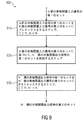
図9は、複数の非相関器入力信号に基づいて、複数の非相関信号を供給するような方法900のフローチャートを示す。
9. FIG. 9 illustrates a method for providing a plurality of decorrelation signals based on a plurality of decorrelator input signals. 2 shows a flowchart of a
方法900は、N個の非相関器入力信号の第1のセットをK個の非相関器入力信号の第2のセットにプレミックスするステップ910を含み、Kは、Nよりも小さい。方法900は、K個の非相関器入力信号の第2のセットに基づいて、K’個の非相関器出力信号の第1のセットを供給するステップ920も含む。例えば、K’個の非相関器出力信号の第1のセットは、非相関化を使用してK個の非相関器入力信号の第2のセットに基づいて供給され、そして、それは、例えば、非相関器の主要部を使用するか、または非相関化アルゴリズムを使用して実行されうる。更に、方法900は、K’個の非相関器出力信号の第1のセットをN’個の非相関器出力信号の第2のセットにポストミックスするステップ930を含み、N’はK’よりも大きい(N’およびK’は整数である)。従って、方法900の出力であるN’個の非相関器出力信号の第2のセットは、方法900に入力されるN個の非相関器入力の第1のセットに基づいて供給されうる。
方法900が、上記のマルチチャネル非相関器と同じ考察に基づく点に留意されたい。さらに、方法900は、個々に、または、組み合わせて、マルチチャネル非相関器に関して(そして、適用できる場合、マルチチャネル・オーディオ・エンコーダに関して)、本願明細書において記載されている特徴および機能のいずれかによって補充されうる点に留意されたい。
Note that
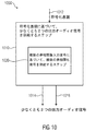
10.図10による符号化表現に基づいて少なくとも2つの出力オーディオ信号を供給する方法
図10は、符号化表現に基づいて少なくとも2つの出力オーディオ信号を供給するための方法1000のフローチャートを示す。
10. Method for providing at least two output audio signals based on the encoded representation according to FIG. 10 FIG. 10 shows a flowchart of a
方法1000は、符号化表現1012に基づいて少なくとも2つの出力オーディオ信号1014,1016を供給するステップ1010を含む。方法1000は、図9による方法900に従って、複数の非相関器入力信号に基づいて複数の非相関化信号を供給するステップ1020を含む。
The
方法1000は、図7によるマルチチャネル・オーディオ・デコーダ700と同じ考察に基づく点に留意されたい。
Note that
また、方法1000は、個々に、または、組み合わせて、マルチチャネル・デコーダに関して、本願明細書において記載されている特徴および機能のいずれかによって補充されうる点に留意されたい。
It should also be noted that the
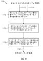
11.図11による少なくとも2つの入力オーディオ信号に基づいて符号化表現を供給する方法
図11は、少なくとも2つの入力オーディオ信号に基づいて符号化表現を供給する方法1100のフローチャートを示す。
11. Method for Providing Coded Representation Based on At least Two Input Audio Signals According to FIG. 11 FIG. 11 shows a flowchart of a
方法1000は、少なくとも2つの入力オーディオ信号1112,1114に基づいて1つ以上のダウンミックス信号を供給するステップ1110を含む。方法1100は、少なくとも2つの入力オーディオ信号1112,1114の間の関係を記述している1つ以上のパラメータを供給するステップ1120も含む。さらに、方法1100は、オーディオ・デコーダのサイドで使用される非相関化の複雑さを記述している非相関化複雑さパラメータを供給するステップ1130を含む。従って、符号化表現1132は、少なくとも2つの入力オーディオ信号1112,1114に基づいて供給される。ここで、符号化表現は、典型的には、符号化形式において、1つ以上のダウンミックス信号、少なくとも2つの入力オーディオ信号の間の関係を記述している1つ以上のパラメータ、および非相関化複雑さパラメータを含む。
ステップ1110,1120,1130は、並行して、または本発明によるいくつかの実施の形態における異なる命令において実行されうる。さらに、方法1100は、図8によるマルチチャネル・オーディオ・エンコーダ800として同じ考察に基づき、そして、方法1100は、個々に、または、組み合わせて、マルチチャネル・オーディオ・エンコーダに関して、本願明細書において記載されている特徴および機能のいずれかによって補充されうる点に留意されたい。さらに、方法1100は、マルチチャネル・オーディオ・デコーダおよび本願明細書において記載されている少なくとも2つの出力オーディオ信号を供給するための方法をマッチするように適応されうる点に留意されたい。
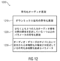
12.図12による符号化オーディオ表現
図12は、本発明の実施の形態による符号化オーディオ表現の概略図を示す。符号化オーディオ表現は、ダウンミックス信号の符号化表現1210、少なくとも2つの入力オーディオ信号の間の関係を記述している1つ以上のパラメータの符号化表現1220、およびオーディオ・デコーダのサイドにおいて使用される非相関化の複雑さを記述している符号化非相関化複雑さパラメータ1230を含む。従って、符号化オーディオ表現1200は、改良された復号化効率、および改良されたオーディオ品質または符号化効率とオーディオ品質とのトレードオフの改良の可能性をもたらすマルチチャネル・オーディオ・デコーダによって使用される非相関化の複雑さを調整することを許容する。さらに、符号化オーディオ表現1200は、本願明細書において記載されるようにマルチチャネル・オーディオ・エンコーダによって供給されえ、そして、本願明細書において記載されるようにマルチチャネル・オーディオ・エンコーダによって使用されうる点に留意されたい。従って、符号化オーディオ表現1200は、マルチチャネル・オーディオ・エンコーダに関しておよびマルチチャネル・オーディオ・デコーダに関して記載される特徴のいずれかによって補充されうる。
12 Encoded Audio Representation According to FIG. 12 FIG. 12 shows a schematic diagram of an encoded audio representation according to an embodiment of the present invention. The encoded audio representation is used at the side of the encoded
13.表記法および基本的な検討事項
近年では、複数のオーディオ・オブジェクトを含んでいるオーディオ・シーンのビットレートの効果的な伝送/格納のためのパラメータの技術は、オーディオ符号化の分野(例えば、参考文献[BCC][JSC][SAOC][SAOC1][SAOC2]を参照)およびインフォームド(informed)音源分離の分野(例えば、参考文献[ISS1][ISS2][ISS3][ISS4][ISS5][ISS6]を参照)において提案されている。これらの技術は、伝送され/格納されたオーディオ・シーンおよび/またはオーディオ・シーンにおける音源オブジェクトを記述している追加のサイド情報に基づいて、所望の出力オーディオ・シーンまたはオーディオ音源オブジェクトを再構成することを意図する。この再構成は、パラメータのインフォームド音源分離を使用してデコーダにおいて生じる。さらに、参照は、例えば、国際標準ISO/IEC 23003−1:2007において記載されるいわゆる「MPEG Surround(MPEGサラウンド)」のコンセプトにもなされる。さらに、参照は、国際標準ISO/IEC 23003−2:2010において記載されるいわゆる「Spatial Audio Object Coding(空間オーディオ・オブジェクト符号化)」にもなされる。さらに、参照は、国際規格ISO/IEC 23003−3:2012において記載されるいわゆる「Unified Speech and Audio Coding(音声音響統合符号化方式)」にもなされる。これらの標準からのコンセプトは、例えば、本願明細書において記載されるマルチチャネル・オーディオ・エンコーダおよび本願明細書において記載されるマルチチャネル・オーディオ・デコーダにおいて、本発明による実施の形態において使用される。ここで、いくつかの適応は必要とされうる。
13. Notation and Basic Considerations In recent years, parameter techniques for the effective transmission / storage of bit rates in audio scenes containing multiple audio objects have been used in the field of audio coding (eg reference Reference [BCC] [JSC] [SAOC] [SAOC1] [SAOC2]) and the field of informed sound source separation (eg, references [ISS1] [ISS2] [ISS3] [ISS4] [ISS5] (See [ISS6]). These techniques reconstruct the desired output audio scene or audio source object based on the transmitted / stored audio scene and / or additional side information describing the source object in the audio scene. I intend to. This reconstruction occurs at the decoder using parametric informed source separation. Furthermore, reference is also made to the so-called “MPEG Surround” concept described, for example, in the international standard ISO / IEC 2303-1: 2007. Reference is also made to the so-called “Spatial Audio Object Coding” described in the international standard ISO / IEC 23003-2: 2010. Reference is also made to the so-called “Unified Speech and Audio Coding” described in the international standard ISO / IEC 23003-3: 2012. The concepts from these standards are used in embodiments according to the present invention, for example, in the multi-channel audio encoder described herein and the multi-channel audio decoder described herein. Here, some adaptations may be required.
以下に、いくつかの背景情報が、記載される。特に、パラメータの分離方式における概要は、MPEG空間オーディオ・オブジェクト符号化(Spatial Audio Object Coding:SAOC)技術(例えば、参考文献[SAOC]を参照)の実施例を使用して、提供される。この方法の数学的プロパティは、考慮される。 In the following, some background information is described. In particular, an overview of parameter separation schemes is provided using examples of MPEG Spatial Audio Object Coding (SAOC) technology (see, eg, reference [SAOC]). The mathematical properties of this method are taken into account.
一般的な損失なしに、方程式の可読性を改良するために、すべての導入される変数に対して、時間および周波数依存を表示しているインデックスは、この明細書において省略される。 In order to improve the readability of the equation without general loss, an index displaying time and frequency dependence for all introduced variables is omitted in this specification.
13.2 パラメータ分離システム
一般的なパラメータ分離システムは、(例えば、内部チャネル相関値、内部チャネルレベル差値、内部オブジェクト相関値および/またはオブジェクト・レベル差情報のような)補助的なパラメータ情報を使用して信号混合(ダウンミックス)からオーディオ音源の数を推定することを意図する。この作業の典型的な解決は、最小2乗平均誤差(Minimum Mean Squared Error:MMSE)推定アルゴリズムのアプリケーションに基づく。SAOC技術は、パラメトリックオーディオ符号化/復号化システムのような1つの実施例である。
13.2 Parameter Separation System A general parameter separation system provides auxiliary parameter information (such as internal channel correlation values, internal channel level difference values, internal object correlation values and / or object level difference information). It is intended to be used to estimate the number of audio sources from signal mixing (downmix). A typical solution to this task is based on the application of the Minimum Mean Squared Error (MMSE) estimation algorithm. SAOC technology is one example, such as a parametric audio encoding / decoding system.
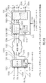
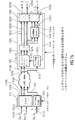
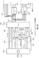
図13は、SAOCエンコーダ/デコーダ構造の一般的な原理を示す。換言すれば、図13は、パラメトリックダウンミックス/アップミックスのコンセプトに基づくMMSEの概観を、ブロック概略図の形式で示す。 FIG. 13 shows the general principle of the SAOC encoder / decoder structure. In other words, FIG. 13 shows an overview of MMSE based on the parametric downmix / upmix concept in the form of a block schematic.
エンコーダ1310は、複数のオブジェクト信号1312a,1312b〜1312nを受信する。さらに、エンコーダ1310は、例えば、ダウンミックス・パラメータであるミキシング・パラメータD,1314も受信する。エンコーダ1310は、それに基づいて、1つ以上のダウンミックス信号1316a,1316b等を供給する。さらに、エンコーダは、サイド情報1318を供給する。1つ以上のダウンミックス信号およびサイド情報は、例えば、符号化形式で供給されうる。
The
エンコーダ1310は、典型的には、オブジェクト信号1312a〜1312nを受信し、ミキシング・パラメータ1314に基づいて、オブジェクト信号1312a〜1312nを結合して(例えば、ダウンミックスして)1つ以上のダウンミックス信号1316a,1316bを作成するように構成されるミキサ1320を含む。さらに、エンコーダは、オブジェクト信号1312a〜1312nからサイド情報1318を導出するように構成されるサイド情報推定器1330を含む。例えば、サイド情報推定器1330は、サイド情報が、例えば、(「内部オブジェクト相関」(IOC:inter−object−correlation))として指定されうる)オブジェクト信号の間の相互相関および/または(「オブジェクト・レベル差情報」(OLD:object level information)として指定されうる)オブジェクト信号の間のレベル差を記述している情報である、オブジェクト信号の間の関係を記述するようなサイド情報1318を導出するように構成されうる。
Encoder 1310 typically receives object signals 1312a-1312n and combines (eg, downmixes) one or more downmix signals based on mixing
1つ以上のダウンミック信号1316a,1316bおよびサイド情報1318は、参照番号1340に示されるように、デコーダ1350に格納されおよび/または送信されうる。
One or
デコーダ1350は、(例えば、符号化形式で)1つ以上のダウンミックス信号1316a,1316bおよびサイド情報1318を受信し、そして、それに基づいて、複数の出力オーディオ信号1352a〜1352nを供給する。デコーダ1350は、(レンダリング行列を定義しうる)1つ以上のレンダリング・パラメータを含みうるユーザ相互作用情報1354も受信する。デコーダ1350は、パラメトリック・オブジェクト・セパレータ1360、サイド情報プロセッサ1370およびレンダラ1380を含む。サイド情報プロセッサ1370は、サイド情報1318を受信し、それに基づいて、パラメトリック・オブジェクト・セパレータ1360に対して制御情報1372を供給する。パラメトリック・オブジェクト・セパレータ1360は、ダウンミックス信号1360a,1360bおよびサイド情報プロセッサ1370によってサイド情報1318から導出された制御情報1372に基づいて、複数のオブジェクト信号1362a〜1362nを供給する。例えば、オブジェクト・セパレータは、符号化ダウンミックス信号およびオブジェクト分離の復号化を実行しうる。レンダラ1380は、それによって出力オーディオ信号1352a〜1352nを得るために、再構成オブジェクト信号1362a〜1362nをレンダリングする。
以下に、パラメータ・ダウンミックス/アップミックスのコンセプトに基づくMMSEの機能が述べられる。 In the following, the function of MMSE based on the parameter downmix / upmix concept will be described.
一般的なパラメトリックダウンミックス/アップミックス処理は、時間/周波数の選択的な方法で実行され、以下のステップのシーケンスとして記載されうる。 The general parametric downmix / upmix process is performed in a time / frequency selective manner and can be described as a sequence of the following steps.
・「エンコーダ」1310は、入力された「オーディオ・オブジェクト」Xおよび「ミキシング・パラメータ」Dを有する。「ミキサ」1320は、「ミキシング・パラメータ」D(例えば、ダウンミックスゲイン)を使用して「オーディオ・オブジェクト」Xをいくつかの「ダウンミックス信号」Yにダウンミックスする。「サイド情報推定器」は、入力された「オーディオ・オブジェクト」X(例えば、共分散特性)の特性を記述しているサイド情報1318を抽出する。
“Encoder” 1310 has input “Audio Object” X and “Mixing Parameter” D. The “mixer” 1320 downmixes the “audio object” X into a number of “downmix signals” Y using a “mixing parameter” D (eg, downmix gain). The “side information estimator” extracts
・「ダウンミックス信号」Yおよびサイド情報は、送信されるか、または格納される。これらのダウンミックスオーディオ信号は、さらに、オーディオコーダ(例えば、MPEG−1/2 Layer IIまたはIII,MPEG−2/4 Advanced Audio Coding(AAC),MPEG Unified Speech and Audio Coding(USAC)等)を使用して圧縮されうる。サイド情報は、(例えば、オブジェクトパワーおよびオブジェクト相関係数の無損失性符号化関係として)効果的に再構成され、符号化されうる。 “Downmix signal” Y and side information are transmitted or stored. These downmix audio signals further use an audio coder (eg MPEG-1 / 2 Layer II or III, MPEG-2 / 4 Advanced Audio Coding (AAC), MPEG Unified Speech and Audio Coding (USAC), etc.). And can be compressed. Side information can be effectively reconstructed and encoded (eg, as a lossless encoding relationship of object power and object correlation coefficient).
さらに、エンコーダ1310およびデコーダ1350に関して記載されている機能は、同様に本願明細書において記載されている他のオーディオ・エンコーダおよびオーディオ・デコーダにおいて使用されうる点に留意されたい。
Furthermore, it should be noted that the functions described with respect to
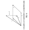
結果として、推定誤差および推定自身は、直交する。
![]()
![]()
幾何学的に、図14に示される例によって、これを視覚化しうる。 Geometrically, this can be visualized by the example shown in FIG.
我々に、2つのオーディオ信号を使用して音源を再生する実施例を考慮させる。IOC値が1に近い場合、音は、極めて局所化された点の音源として知覚される。IOC値がゼロに近い場合、音源の知覚された幅は増加し、そして、極端な例では、2つの異なった音源としてとして知覚されることさえある[Blauert,第3章]。 Let us consider an example of playing a sound source using two audio signals. If the IOC value is close to 1, the sound is perceived as a very localized point sound source. When the IOC value is close to zero, the perceived width of the sound source increases and in extreme cases it can even be perceived as two different sound sources [Blauert, Chapter 3].
13.6 再構成誤りの補償
不完全なパラメトリック再構成の場合、出力信号は、元のオブジェクトと比較して低いエネルギーを示しうる。共分散行列の対角要素の誤差は、(理想的な参照出力と比較して)聞き取れるレベル差、および歪められた空間音像における非対角要素での誤差を結果として得る。提案された方法は、この課題を解決するための目的を有する。
13.6 Reconstruction Error Compensation In the case of incomplete parametric reconstruction, the output signal may exhibit low energy compared to the original object. The errors in the diagonal elements of the covariance matrix result in audible level differences (compared to the ideal reference output) and errors in off-diagonal elements in the distorted spatial sound image. The proposed method has the purpose to solve this problem.
MPEG Surround(MPS)において、例えば、この問題は、いくつかの特定のチャネル・ベースの処理シナリオ、すなわち、モノラル/ステレオダウンミックスおよび限られた静的な出力構造(例えば、モノラル,ステレオ,5.1,7.1等)ためだけに扱われる。SAOCのようにモノラル/ステレオダウンミックスも使用するオブジェクト指向技術において、この課題は、5.1の出力構造だけのためのMPS後処理レンダリングを適用することによって扱われる。 In MPEG Surround (MPS), for example, this problem is addressed in several specific channel-based processing scenarios: mono / stereo downmix and limited static output structures (eg, mono, stereo, 5.. 1, 7.1 etc.). In object-oriented technologies that also use mono / stereo downmix, such as SAOC, this challenge is addressed by applying MPS post-processing rendering for 5.1 output structures only.
既存の解決策は、標準の出力構成および入出力チャネルの定数に限られる。すなわち、それらは、ちょうど「モノラル対ステレオ」(または「ステレオ対3チャネル」)のチャネル非相関を実装しているいくつかのブロックの結果として生じるアプリケーションとして理解される。 Existing solutions are limited to standard output configurations and I / O channel constants. That is, they are understood as applications that result from several blocks implementing just “mono vs. stereo” (or “stereo vs. 3 channels”) channel decorrelation.
それゆえに、パラメトリック再構成誤りの補償のための一般的な解決策(例えば、エネルギーレベルおよび相関特性修正方法)が所望され、そして、それは柔軟な数のダウンミックス/出力チャネルおよび任意の出力構成セットアップに対して適用されうる。 Therefore, a general solution for parametric reconstruction error compensation (eg, energy level and correlation characteristic correction methods) is desired, and it is a flexible number of downmix / output channels and any output configuration setup Can be applied.
13.7 結論
結論として、表記法に関する概要が提供された。さらに、パラメトリック分離システムは、本発明による実施の形態がベースであることが述べられた。さらに、最小2乗平均誤差推定に適用される直交原理が概説された。さらに、再構成誤差XErrorの存在において適用する共分散行列EXの算出のための方程式が提供された。また、例えば、本発明による実施の形態において、(パラメトリックサイド情報において含まれうる)内部オブジェクト相関値から所望の共分散特性(または相関特性)を導出し、そして、おそらくオブジェクト・レベル差を形成するために適用されうる、いわゆる内部オブジェクト相関および共分散行列EXの要素との間の関係が提供された。さらに、再構成オブジェクト信号の特性が、不完全な再構成のため、所望の特性と異なることが概説された。さらに、課題を取り扱う既存の解決策が、いくつかの特定の出力構成に限られており、従来の解決策の変更できない標準ブロックの特定の結合に依拠することが概説された。
13.7 Conclusion In conclusion, a summary of notation was provided. Furthermore, it has been stated that the parametric separation system is based on an embodiment according to the invention. In addition, the orthogonal principle applied to least mean square error estimation was outlined. Furthermore, equations for calculating the covariance matrix E X to be applied in the presence of a reconstruction error X Error is provided. Also, for example, in an embodiment according to the present invention, a desired covariance characteristic (or correlation characteristic) is derived from an internal object correlation value (which may be included in the parametric side information) and possibly forms an object level difference. may be applied, the relationship between the elements of the so-called internal object correlation and covariance matrix E X provided for. Furthermore, it has been outlined that the characteristics of the reconstructed object signal differ from the desired characteristics due to incomplete reconstruction. In addition, it has been outlined that existing solutions that deal with issues are limited to some specific output configurations and rely on specific combinations of standard blocks that cannot be modified by conventional solutions.
14.図15による実施の形態
14.1 コンセプトの概要
本発明による実施の形態は、任意の数のダウンミックス/アップミックスチャネルのための非相関化の解決策を有するパラメトリックオーディオ分離方式において使用されるMMSEパラメトリック再構成方法を拡張する。例えば、発明の装置および発明の方法のような本発明による実施の形態は、パラメトリック再構成の間のエネルギー損失を補償することができ、そして、推定されたオブジェクトの相関特性を復元しうる。
14
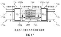
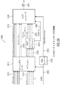
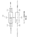
図15は、統合された非相関化経路を有するパラメトリックダウンミックス/アップミックスのコンセプトの概要を提供する。換言すれば、ブロック概略図の形式において、レンダリングされた出力に適用される非相関化を伴うパラメトリック再構成システムを示す。 FIG. 15 provides an overview of the parametric downmix / upmix concept with an integrated decorrelation path. In other words, in the form of a block schematic, a parametric reconstruction system with decorrelation applied to the rendered output is shown.
図15に記載のシステムは、図13に記載のエンコーダ1310と実質的に同一であるエンコーダ1510を含む。エンコーダ1510は、複数のオブジェクト信号1512a〜1512nを受信し、そして、それに基づいて、1つ以上のダウンミックス信号1516a,1516bおよびサイド情報1518を供給する。ダウンミックス信号1516a,1516bは、ダウンミックス信号1316a,1316bと実質的に同一でありえ、そして、Yによって指定される。サイド情報1518は、サイド情報1318と実質的に同一でありうる。しかしながら、例えば、サイド情報は、非相関化モードパラメータ、または非相関化方法パラメータ、または非相関化複雑さパラメータを含む。さらに、エンコーダ1510は、ミキシング・パラメータ1514を受信しうる。
The system described in FIG. 15 includes an
パラメトリック再構成システムは、1つ以上のダウンミックス信号1516a,1516bおよびサイド情報1518の送信および/または格納も含む。ここで、送信および/または格納は、1540で指定され、1つ以上のダウンミックス信号1516a,1516bおよび(パラメトリックサイド情報を含みうる)サイド情報1518が、符号化されうる。
The parametric reconstruction system also includes transmission and / or storage of one or
さらに、図15によるパラメトリック再構成システムは、送信されまたは格納された1つ以上の(あるいは符号化)ダウンミックス信号1516a,1516bおよび送信されまたは格納された(あるいは符号化)サイド情報1518を受信し、そして、それに基づいて、出力オーディオ信号1552a〜1552nを供給するように構成される、デコーダ1550を含む。(マルチチャネル・オーディオ・デコーダとして考慮されうる)デコーダ1550は、パラメトリック・オーディオ・セパレータ1560およびサイド情報プロセッサ1570を含む。さらに、デコーダ1550は、レンダラ1580、非相関器1590およびミキサ1598を含む。
Further, the parametric reconstruction system according to FIG. 15 receives one or more (or encoded)
非相関器1590は、レンダリングされたオーディオ信号1582a〜1582nを受信し、そして、それに基づいて、Wでも指定される非相関化オーディオ信号1592a〜1592nを供給する。ミキサ1598は、レンダリングされたオーディオ信号1582a〜1582nおよび非相関化オーディオ信号1592a〜1592nを受信し、そして、レンダリングされたオーディオ信号1582a〜1582nと非相関化オーディオ信号1592a〜1592nとを結合し、それによって、出力オーディオ信号1552a〜1552nを得る。ミキサ1598は、後述するように、符号化サイド情報1518からサイド情報プロセッサ1570によって導出される制御情報1574も使用しうる。
A
14.2 非相関器の関数
以下に、非相関器1590に関する若干の詳細が記載される。しかしながら、いくつか後述されるように、異なる非相関器が使用されうる点に留意されたい。
14.2 decorrelator functions In the following, some details regarding the
非相関器の関数の実装のための正確な仕様は、この説明の範囲の外である。例えば、MPEG Surround Standardにおいて特定された非相関器に基づく、いくつかの無限インパルス応答(IIR)フィルタのバンクは、非相関化の目的のために利用されうる([MPS])。 The exact specification for the implementation of the decorrelator function is outside the scope of this description. For example, a bank of several infinite impulse response (IIR) filters, based on the decorrelator identified in MPEG Surround Standard, may be utilized for decorrelation purposes ([MPS]).
これらの関係から、
![]()
![]()
非相関器出力Wは、入力として予測された信号を使用することによって、(予測誤差が予測信号に対して直交することを記憶している)MMSE推定器における予測誤りを補償するように使用されうる。 The decorrelator output W is used to compensate for prediction errors in the MMSE estimator (which remembers that the prediction error is orthogonal to the prediction signal) by using the predicted signal as input. sell.
それは、予測誤差がそれら自身の間において直交する一般的な場合ではない点に留意されたい。このように、結果として得られるミクスチャーの共分散行列(例えば、出力オーディオ信号1552a〜1552n)が所望の出力の共分散行列に類似することになるように、本発明のコンセプト(例えば、方法)の目的1つは、「ドライ」(すなわち、非相関器入力)信号(例えば、レンダリングされたオーディオ信号1582a〜1582n)および「ウェット」(すなわち、非相関器出力)信号(例えば、非相関化オーディオ信号1592a〜1592n)のミクスチャーを作成することである。
Note that it is not the general case that the prediction errors are orthogonal between themselves. Thus, the inventive concept (eg, method) is such that the resulting mixture covariance matrix (eg,
さらに、以下に詳細に記載され、そして、しかしながら、受け入れられる、非相関化信号のいくつかの欠点をもたらす、非相関化装置のための複雑さの低減が使用される点に留意されたい。 Furthermore, it should be noted that a complexity reduction for the decorrelation device is used, which is described in detail below and, however, introduces some disadvantages of the decorrelation signal.
14.3 非相関化信号を使用している出力共分散修正
以下に、コンセプトが、合理的に良好な聴覚印象を得るように、出力オーディオ信号1552a〜1552nの共分散特性を調整することを記載している。
14.3 Output covariance correction using decorrelated signals The following describes that the concept adjusts the covariance characteristics of the
しかしながら、この方程式は、もっとも一般的な定式化と考えられる点に留意されたい。変化は、本願明細書において記載されているすべての「簡略化された方法」に通用する(または、させ得る)上記の公式に、任意に適用されうる。 However, it should be noted that this equation is considered the most general formulation. Variations can optionally be applied to the above formulas that are (or can be) accepted by all “simplified methods” described herein.
あるいは、一方、後で詳しく述べるように、以下の方程式
![]()
![]()
理想的に作成されレンダリングされた出力シーンのターゲット共分散Cは、
C=REXRH
として、定義される。
The target covariance C of the ideally created and rendered output scene is
C = RE X R H
Is defined as
原型の行列Hは、直接的なおよび非相関信号パスのために所望の加重に従って選択されうる。 The original matrix H can be selected according to a desired weight for direct and uncorrelated signal paths.
例えば、可能な原型行列Hは、
以下に、一般の行列Fの構造のための若干の数学的な導出が提供される。 In the following, some mathematical derivations for the structure of the general matrix F are provided.
換言すれば、一般的な解決法のための混合行列Fの導出は、以下において記載される。 In other words, the derivation of the mixing matrix F for a general solution is described below.
共分散行列ESおよびCは、
ES=VQVH,C=UTUH
として、例えば、特異値分解(SVD)を使用して表わされ、TおよびQは、それぞれCおよびESの特異値を有する対角行列であり、UおよびVは、特異ベクトルに対応するユニタリ行列である。
The covariance matrices E S and C are
E S = VQV H , C = UTU H
For example, using singular value decomposition (SVD), where T and Q are diagonal matrices with singular values of C and E S , respectively, and U and V are unitary corresponding to singular vectors. It is a matrix.
(SVDの代わりに)シューア三角化または固有値分解のアプリケーションが、類似の結果(または、対角行列QおよびTが正値に限定される場合、同一の結果)に至ることに留意されたい。 Note that Schur triangulation or eigenvalue decomposition applications (instead of SVD) lead to similar results (or identical results if the diagonal matrices Q and T are limited to positive values).
原型行列Hは、直接的なおよび非相関化信号パスのための所望の加重によって選択される。例えば、可能な原型行列Hは、
結合信号の共分散行列ESの条件に応じて、最後の方程式は、いくつかの正則化を含むことを必要としうるが、さもなければ、数値的に安定でなければならない。 Depending on the conditions of the covariance matrix E S of the combined signal, the last equation may need to include some regularization, but otherwise it must be numerically stable.
しかしながら、あるいは、サイド情報プロセッサ1570は、情報1574として、ミキサ1598に直接的に混合行列Fを供給も、しうる。
However, alternatively, the
さらに、混合行列Fのための計算規則は、特異値分解を使用することを記載されていた。しかしながら、原型行列Hの入力ai,iおよびbi,iが選択されうるので、ある自由度がある点に留意されたい。好ましくは、原型行列Hの入力は、およそ0および1の間で選択される。非相関化オーディオ信号のインパクトは、比較的小さく、そして、それは、若干の状況において望ましくもある一方、値ai,iが1に近づくように選択されうる場合、レンダリングされた出力オーディオ信号の重要な混合がある。しかしながら、レンダリングされたオーディオ信号の間における弱い混合がある一方、若干の他の状況において、非相関化オーディオ信号の比較的大きいインパクトを有することをより望まれうる。この場合、値bi,iは、ai,iより大きいように典型的に選択される。このように、デコーダ1550は、原型行列Hの入力を適切に選択することによって、前提条件に適応されうる。
Furthermore, the calculation rules for the mixing matrix F have been described using singular value decomposition. However, it should be noted that there are certain degrees of freedom since the inputs a i, i and b i, i of the prototype matrix H can be selected. Preferably, the input of the prototype matrix H is selected between approximately 0 and 1. The impact of the uncorrelated audio signal is relatively small, and it may be desirable in some situations, while the value a i, i can be chosen to approach 1, the importance of the rendered output audio signal There is a mix. However, while there is weak mixing between rendered audio signals, in some other situations it may be more desirable to have a relatively large impact of uncorrelated audio signals. In this case, the value b i, i is typically chosen to be greater than a i, i . In this way, the
14.4 出力共分散修正のための簡略化された方法
このセクションにおいて、前述の混合行列Fのための2つの変形例の構造は、その値を決定するための典型的なアルゴリズムとともに記載される。2つの変形例は、異なる入力コンテンツ(例えば、オーディオ・コンテンツ)のために設計される。
− 高い相関コンテンツ(例えば、異なるチャネル対の間の高い相関を伴うチャネル・ベースの入力)のための共分散調整方法
− 独立入力信号(例えば、たいてい独立とみなされる、オブジェクト・ベースの入力)のためのエネルギー補償方法
14.4 Simplified Method for Output Covariance Modification In this section, the two variant structures for the mixing matrix F described above are described along with a typical algorithm for determining their values. . The two variants are designed for different input content (eg audio content).
-Covariance adjustment method for high correlation content (eg channel-based input with high correlation between different channel pairs)-Independent input signal (eg object-based input, usually considered independent) Energy compensation method for
非相関化信号Wの混合が操作されれば、混合行列Pは、単位行列(または、その倍数)に低減されうる。このように、この簡略化された方法は、
システムの最後の出力は、
![]()
![]()
従って、システムの最後の出力共分散は、
![]()
![]()
従って、混合行列Mは、
![]()
![]()
このアプローチは、ドライ出力(例えば、レンダリングされたオーディオ信号1582a〜1582n)を使用する良好な相互相関再構成の最大化を確実にし、そして、非相関化信号のみの混合の自由を利用する。換言すれば、レンダリングされたオーディオ信号(または、そのスケール化バージョン)と1つ以上の非相関化オーディオ信号とを結合する場合、異なるレンダリングされたオーディオ信号の間の混合は許容されない。しかしながら、出力オーディオ信号の相互相関特性または相互共分散特性を調整するために、所与の非相関化信号は、同じもしくは異なるスケール化、複数のレンダリングされたオーディオ信号、またはそのスケール化バージョンを結合することを許容する。ここで、定義されるように、例えば、結合は、行列Mによって定義される。
This approach ensures good cross-correlation reconstruction maximization using dry output (eg, rendered
以下に、制限行列F構造のためのいくつかの数学的な導出が提供される。 In the following, some mathematical derivations for the restriction matrix F structure are provided.
換言すれば、簡略化された方法「A」のための混合行列Mの導出が説明される。 In other words, the derivation of the mixing matrix M for the simplified method “A” is described.
共分散行列ΔEおよびEWは、
ΔE=UTUH,EW=VQVH
として、例えば、特異値分解(SVD)を使用して表わされ、TおよびQは、それぞれΔEおよびEWの特異値を有する対角行列であり、UおよびVは、対応する特異ベクトルを含むユニタリ行列である。
The covariance matrices Δ E and E W are
Δ E = UTU H , E W = VQV H
For example, using singular value decomposition (SVD), where T and Q are diagonal matrices with singular values of Δ E and E W , respectively, and U and V are the corresponding singular vectors Is a unitary matrix.
(SVDの代わりに)シューア三角化または固有値分解のアプリケーションが、類似の結果(または、対角行列QおよびTが正値に限定される場合、同一の結果)に至ることに留意されたい。 Note that Schur triangulation or eigenvalue decomposition applications (instead of SVD) lead to similar results (or identical results if the diagonal matrices Q and T are limited to positive values).
方程式の両側が行列の正方形を表す点に留意して、我々は積算を落とし、全行列Mのために解決する。 Note that both sides of the equation represent a square of the matrix, we drop the integration and solve for the entire matrix M.
混合行列Mは、
![]()
![]()
この方法は、
ウェット信号の共分散行列EWの条件に応じて、最後の方程式は、いくつかの正則化を含むことを必要としうるが、さもなければ、数値的に安定でなければならない。 Depending on the conditions of the wet signal covariance matrix E W , the last equation may need to contain some regularization, but otherwise it must be numerically stable.
14.4.2 エネルギー補償方法(B)
時々(アプリケーション・シナリオに応じて)、(例えば、レンダリングされたオーディオ信号の)パラメトリック再構成または非相関化信号の混合を許容することを望まないが、しかし、個々に、各パラメータ的に再構成された信号(例えば、レンダリングされたオーディオ信号)とそれ自身の非相関化信号のみを混合することが望ましい。
14.4.2 Energy compensation method (B)
Sometimes (depending on the application scenario) we do not want to allow mixing of parametric reconstructions (eg of rendered audio signals) or decorrelated signals, but individually reconstructing each parameter It is desirable to mix only the rendered signal (eg, the rendered audio signal) and its own decorrelated signal.
この前提条件を達成するために、追加の制約は、簡略化方法「A」にもたらされうる。現在、ウェット信号(非相関化信号)の混合行列Mが、対角形式を有することを必要とする。
このアプローチの主な目標は、パラメトリック再構成(例えば、レンダリングされたオーディオ信号)におけるエネルギーの損失を補償するように、非相関化信号を使用することになっている一方、出力信号の共分散行列の対角線の修正が無視される、すなわち、相互相関の直接的な取り扱いは、ない。従って、出力オブジェクト/チャネルの間(例えば、レンダリングされたオーディオ信号の間)のクロスリークは、非相関化信号のアプリケーションにおいて導かれない。 The main goal of this approach is to use a decorrelated signal to compensate for energy loss in parametric reconstruction (eg, rendered audio signal), while the output signal covariance matrix Diagonal correction is ignored, ie there is no direct handling of cross-correlation. Thus, cross leaks between output objects / channels (eg, between rendered audio signals) are not introduced in decorrelated signal applications.
その結果、ターゲット共分散行列(または所望の共分散行列)の主対角線のみに達し、非対角は、パラメトリック再構成および付加的な非相関化信号の精度の軽減にある。この方法は、信号が相関関係のないように考慮されるオブジェクトのみのベースのアプリケーションに最も適している。 As a result, only the main diagonal of the target covariance matrix (or the desired covariance matrix) is reached, and the off-diagonal is in the parametric reconstruction and the reduction in accuracy of the additional decorrelated signal. This method is best suited for object-only based applications where the signals are considered uncorrelated.
Cは、一般のケースのために前述したように決定されうる。 C can be determined as described above for the general case.
例えば、混合行列Mは、(オーディオ・デコーダによって決定されうる)非相関化信号のエネルギーを伴う補償信号の所望のエネルギー((相互共分散行列Cの対角要素によって記述されうる)所望のエネルギーと(オーディオ・デコーダによって決定されうる)パラメトリック再構成のエネルギーとの間の差)を分割することによって直接的に導出されうる。
エネルギーは、(例えば、OLD,IOC、およびレンダリング係数を使用して)パラメータ的に再構成されうるか、または、(典型的に、より計算的に価値のある)デコーダによって実質的に算出されうる点に留意されたい。 The energy can be reconstructed parametrically (eg, using OLD, IOC, and rendering coefficients) or can be substantially calculated by a decoder (typically more computationally valuable) Please note that.
この方法は、
この方法は、明確に、ドライのレンダリングされた出力の使用を最大にする。共分散行列が非対角の入力を有さない場合、方法は、単純化の「A」を伴うものと等価である。 This method clearly maximizes the use of dry rendered output. If the covariance matrix has no off-diagonal inputs, the method is equivalent to that with a simplification “A”.
この方法は、低減された計算量の複雑さを有する。 This method has a reduced computational complexity.
しかしながら、エネルギー補償方法は、相互相関条件が修正されないことを必ずしも意味するものではない点に留意されたい。我々が、理想的な非相関器および非相関化装置のための複雑さの低減でないことを使用する場合だけ、これは保持する。方法の意図は、エネルギーを回復して、交差項における修正を無視することである(交差項における変化は、相関特性を実質的に修正せず、全体の空間印象に影響を及ぼさない)。 However, it should be noted that the energy compensation method does not necessarily mean that the cross-correlation condition is not modified. This holds only if we use not the complexity reduction for an ideal decorrelator and decorrelator. The intent of the method is to restore energy and ignore corrections in the cross term (changes in the cross term do not substantially correct the correlation properties and do not affect the overall spatial impression).
14.5 混合行列Fの前提条件
以下に、混合行列F、セクション14.3および14.4において記載されているその導出は、低下を回避する必要性を満たすと説明される。
14.5 Preconditions for Mixing Matrix F In the following, the derivation described in Mixing Matrix F, sections 14.3 and 14.4 is described as satisfying the need to avoid degradation.
出力における低下を回避するために、パラメトリック再構成誤差のための補償をするいかなる方法が、以下の特性を有する結果をもたらさなければならない。レンダリング行列が、ダウンミックス行列に等しい場合、そのとき、出力チャネルは、ダウンミックスチャネルと等しい(または、少なくとも近似する)べきである。提案されたモデルは、この特性を満足させる。レンダリング行列は、ダウンミックス行列と等しい場合R=D、パラメトリック再構成は、
![]()
C=REXRH=DEXDH=EY
である。
In order to avoid a drop in output, any method that compensates for parametric reconstruction errors must result in the following characteristics: If the rendering matrix is equal to the downmix matrix, then the output channel should be equal (or at least approximate) to the downmix channel. The proposed model satisfies this property. R = D if the rendering matrix is equal to the downmix matrix, the parametric reconstruction is
![]()
C = RE X RH = DE X DH = E Y
It is.
これは、非相関化信号が、合計する際において、加重ゼロ(zero−weight)を有し、最後の出力は、ドライ信号によって与えられ、そして、それは、ダウンミックス信号と同一である。
![]()
![]()
その結果、このレンダリングシナリオにおいて、ダウンミックス信号に等しいようなシステム出力のための所与の前提条件は満たされる。 As a result, in this rendering scenario, the given preconditions for system output such as equal to the downmix signal are met.
14.6 信号共分散行列ESの推定
混合行列Fを得るために、結合信号Sの共分散行列ESの情報が必要とされるか、または、少なくとも価値がある。
14.6 Estimation of the signal covariance matrix E S To obtain the mixing matrix F, the information of the covariance matrix E S of the combined signal S is required or at least valuable.
非相関器は理想的である(すなわち、エネルギーを保つこと、入力に対して、出力は直交すること、そして、すべての出力は、相互に直交すること)と仮定するならば、共分散行列ESは、
相互に直交および/またはエネルギー保存の仮定が妨害される(例えば、利用可能な非相関器の数が、非相関化される信号の数よりも少ないときのケースにおける)場合、そのとき、共分散行列EWは、
14.7 任意の改良:非相関化信号およびエネルギー調整装置を使用する出力共分散修正
以下に、特に、有利なコンセプトが記載され、そして、それは、本願明細書において記載される他のコンセプトと組み合わされうる。
14.7 Optional improvement: Output covariance correction using decorrelated signal and energy conditioning device In the following, particularly advantageous concepts are described and combined with other concepts described herein Can be done.
しかしながら、この方程式は、最も一般的な定式化と考慮されうる点に留意されたい。変化は、本願明細書において記載されている全ての「簡略化された方法」に対して有効である上記の公式に、任意に適用されうる。 However, it should be noted that this equation can be considered the most general formulation. Variations can optionally be applied to the above formulas that are valid for all “simplified methods” described herein.
以下に、例えば、エネルギー調整装置によって実行されうる機能性が記載される。 In the following, for example, the functionality that can be executed by the energy regulating device is described.
上記の方程式において、例えば、独立変数Cestim(i,i)およびεの最大値を供給する分母における「max(.)」は、ゼロによる除算を回避するために、εまたは他のメカニズムの追加によって取り替えられる。 In the above equation, for example, “max (.)” In the denominator supplying the maximum value of the independent variable C estim (i, i) and ε is the addition of ε or other mechanism to avoid division by zero. Replaced by.
![]()
![]()
以下に、いくつかのさらなる簡略化したものが、記載される。換言すれば、出力共分散修正のための簡略化された方法が記載される。 In the following, some further simplifications are described. In other words, a simplified method for output covariance correction is described.
非相関化(ウェット)信号Wの混合が操作されれば、混合行列Pは、単位行列に低減されうる。この場合、パラメータ的に再構成された(ドライ)信号に対応するエネルギー調整行列も、単位行列に低減されうる。このように、簡略化された方法は、
システムの最後の出力は、
![]()
![]()
15.非相関化装置のための複雑さの低減
以下に、本発明による実施の形態において使用される非相関器の複雑さがどのように低減されうるかが記載される。
15. In the following, it will be described how the complexity of the decorrelator used in an embodiment according to the invention can be reduced.
非相関器の機能の実装は、しばしば、計算的に複雑である点に留意されたい。いくつかのアプリケーション(例えば、ポータブル・デコーダ・ソリューション)において、非相関器の数の制限は、制限された計算機のリソースのために導入されることを必要とされうる。このセクションは、適用される非相関器(または非相関化)の数を制御することによって、非相関器の装置の複雑さの低減のための手段の記載を提供する。非相関化装置のインターフェースは、図16および図17において表現される。 Note that the implementation of the decorrelator function is often computationally complex. In some applications (eg, portable decoder solutions), a limit on the number of decorrelators may be required to be introduced due to limited computer resources. This section provides a description of the means for reducing the decorrelator device complexity by controlling the number of decorrelators (or decorrelations) applied. The decorrelator interface is represented in FIGS.
非相関化装置1700は、非相関器出力信号の第1のセットのK個の非相関器出力信号1732a〜1732kを受信し、それに基づいて、(「外部の」非相関器出力信号を構成する)非相関器出力信号の第2のセットのN個の信号1712a〜1712nを供給するように構成される、ポスト・ミキサ1740を含む。
The
プレミキサ1720は、プレミキシング行列Mpreによって記載される線形混合処理を、好ましくは実行しうる。さらに、ポスト・ミキサ1740は、K個の非相関器出力信号1732a〜1732kの第1のセットから(すなわち、非相関器の主要部1730の出力信号から)非相関器出力信号の第2のセットのN個の非相関器出力信号1712a〜1712nを導出するために、ポストミキシング行列Mpreによって表されうる、線形混合(または、アップミックス)処理を、好ましくは実行する。
The
提案された方法と装置の主要な考えは、以下によって、NからKへ、非相関器への(または非相関器の主要部への)入力信号の数を低減することである。 The main idea of the proposed method and apparatus is to reduce the number of input signals from N to K to the decorrelator (or to the main part of the decorrelator) by:
・次式を伴う数を下げるために、信号(例えば、レンダリングされたオーディオ信号)をプレミックスする。
![]()
![]()
・次式を伴う利用可能なK個の非相関器(例えば、非相関器の主要部)を使用して非相関化を適用する。
・次式を伴うN個のチャネルへ非相関化信号をアップミックスする。
![]()
![]()
使用される非相関器(または、個々の非相関器)の数Kは、特定されず、所望の計算量の複雑さおよび利用可能な非相関器に依存している。その値は、(最も高い計算量の複雑さの)N個から(最も低い計算量の複雑さの)1個に至るまで変化する。 The number K of decorrelators (or individual decorrelators) used is not specified and depends on the complexity of the desired complexity and the available decorrelators. Its value varies from N (highest complexity) to 1 (lowest complexity).
非相関器の装置への入力信号の数Nは、任意であり、そして、提案された方法は、システムのレンダリング構造において独立していて、いかなる入力信号の数を支持する。 The number N of input signals to the decorrelator device is arbitrary, and the proposed method is independent in the rendering structure of the system and supports any number of input signals.
例えば、3Dのオーディオ・コンテンツを使用しているアプリケーションにおいて、多数の出力チャネルについては、出力構成に応じて、プレミキシング行列Mpreのためのある可能な表現が後述される。 For example, in an application using 3D audio content, for a number of output channels, depending on the output configuration, some possible representations for the premixing matrix M pre are described below.
以下において、非相関化装置1700がマルチチャネル・オーディオ・デコーダにおいて使用された場合、プレミキサ1720(および、従って、ポスト・ミキサ1740によって実行されるポストミックス)によって実行されるプレミックスが、どのように調整されるかを記載する。ここで、非相関器入力信号の第1のセットの非相関器入力信号1710a〜1710nは、オーディオ・シーンの異なる空間的な位置と関連している。
In the following, if the
この目的のために、図18は、異なる出力フォーマットのために使用されるスピーカ位置のテーブル表現を示す。 For this purpose, FIG. 18 shows a table representation of speaker positions used for different output formats.
図18の表1800において、第1列1810は、スピーカのインデックスナンバーを記載する。第2列1820は、スピーカラベルを記載する。第3列1830は、それぞれのスピーカの方位角の位置を記載し、第4列1832は、スピーカの位置の方位角の許容差を記載する。第5列1840は、それぞれのスピーカの位置の仰角を記載し、第6列1842は、対応する仰角許容差を記載する。第7列1850は、スピーカが出力フォーマットO−2.0のために使用されることを指し示す。第8列1860は、スピーカが出力フォーマットO−5.1のために使用されることを示す。第9列1864は、スピーカが出力フォーマットO−7.1のために使用されることを示す。第10列1870は、スピーカが出力フォーマットO−8.1のために使用されることを示し、第11列1880は、スピーカが出力フォーマットO−10.1のために使用されることを示し、そして、第12列1890は、スピーカが出力フォーマットO−22.2のために使用されることを示す。表に示されるように、2個のスピーカが、出力フォーマットO−2.0のために使用され、6個のスピーカが、出力フォーマットO−5.1のために使用され、8個のスピーカが、出力フォーマット7.1のために使用され、9個のスピーカが、出力フォーマットO−8.1のために使用され、11個のスピーカが、出力フォーマットO−10.1に対して使用され、そして、24個のスピーカが、出力フォーマットO−22.2のために使用される。
In the table 1800 of FIG. 18, the
しかしながら、1つの低音効果のスピーカは、出力フォーマットO−5.1,O−7.1,O−8.1およびO−10.1のために使用され、2つの低音効果のスピーカ(LFE1,LFE2)は、出力フォーマットO−22.2のために使用される点に留意されたい。さらに、好ましい実施の形態において、1つ以上の低音効果のスピーカを除いて、1つのレンダリングされたオーディオ信号(例えば、レンダリングされたオーディオ信号1582a〜1582nのうちの1つ)が、スピーカの各々に関連している点に留意されたい。従って、2つのレンダリングされたオーディオ信号は、O−2.1フォーマットにより使用される2個のスピーカに関連しており、O−5.1フォーマットが使用される場合、5つのレンダリングされたオーディオ信号は、5個の低音効果でないスピーカに関連しており、O−7.1フォーマットが使用される場合、7つのレンダリングされたオーディオ信号は、7個の低音効果でないスピーカに関連しており、O−8.1フォーマットが使用される場合、8つのレンダリングされたオーディオ信号は、8個の低音効果でないスピーカに関連しており、O−10.1フォーマットが使用されう場合、10個のレンダリングされたオーディオ信号が、10個の低音効果でないスピーカに関連しており、そして、O−22.2フォーマットが使用される場合、22個のレンダリングされたオーディオ信号は、22個の低音効果でないスピーカに関連している。
However, one bass effect speaker is used for output formats O-5.1, O-7.1, O-8.1 and O-10.1, and two bass effect speakers (LFE1, Note that LFE2) is used for output format O-22.2. Further, in a preferred embodiment, with the exception of one or more bass effects speakers, one rendered audio signal (eg, one of the rendered
図19a〜図19gは、N=22のレンダリングされたオーディオ信号があるという仮定のもとに、レンダリングされたオーディオ信号1582a〜1582nをプレミックスするための異なるオプションを表す。例えば、図19aは、プレミキシング行列Mpreの入力のテーブル表現を示す。図19aにおける1〜11のラベルを付けられた行は、プレミキシング行列Mpreの行を表し、1〜22のラベルを付けられた列は、プレミキシング行列Mpreの列を表す。さらに、プレミキシング行列Mpreの行の各々は、非相関器入力信号の第2のセットのK個の非相関器入力信号1722a〜1722kのうちの1つ(すなわち、非相関器の主要部の入力信号)に関連している点に留意されたい。さらに、プレミキシング行列Mpreの列の各々は、非相関器入力信号の第1のセットのN個の非相関器入力信号1710a〜1710nのうちの1つに関連しており、そして、その結果、(非相関器入力信号の第1のセットの非相関器入力信号1710a〜1710nが、実施の形態におけるレンダリングされたオーディオ信号1582a〜1582nに典型的に同一であるので)レンダリングされたオーディオ信号1582a〜1582nに関連している。従って、プレミキシング行列Mpreの列の各々は、特定のスピーカに関連し、そして、特定の空間的な位置に関連しているので、その結果、スピーカは空間的な位置に関連している。行1910は、プレミキシング行列Mpreの列が関連しているスピーカ(およびその結果、空間的な位置)を示す(ここで、スピーカのラベルは、表1800の列1820において定義される)。
19a-19g represent different options for premixing rendered
以下において、図19aのプレミキシングMpreによって定義される機能が、さらに詳細に記載される。表に示すように、スピーカ(または、スピーカ位置と同等)「CH_M_000」および「CH_L_000」に関連するレンダリングされたオーディオ信号は、非相関器入力信号の第2のセットの第1の非相関器入力信号(すなわち、第1のダウンミックスされた非相関器入力信号)を得るために結合され、そして、それは、プレミキシング行列Mpreの第1行の第1列および第2列における「1」の値によって指し示される。同様に、スピーカ(または、スピーカ位置と同等)「CH_U_000」および「CH_T_000」に関連するレンダリングされたオーディオ信号は、第2のダウンミックスされた非相関器入力信号(すなわち、非相関器入力信号の第2のセットの第2の非相関器入力信号)を得るために結合される。さらに、11個のダウンミックスされた非相関器入力信号が、22個のレンダリングされたオーディオ信号から導出されるように、図19aのプレミキシング行列Mpreは、2つのレンダリングされたオーディオ信号の11の組み合わせを定義することが示されうる。(プレミキシング行列の1〜4列および1および2行を参照して)2つのダウンミックスされた非相関器入力信号を得るために、4つの中心の信号が結合されることを示す。さらに、他のダウンミックスされた非相関器入力信号が、オーディオ・シーンの同じ側に関連している2つのオーディオ信号を結合することによって各々得られることを示す。例えば、プレミキシング行列の第3行によって表される、第3のダウンミックスされた非相関器入力信号は、+135°(「CH_M_L135」;「CH_U_L135」)の方位角の位置に関連しているレンダリングされたオーディオ信号を結合することによって得られる。さらに、(プレミキシング行列の第4行によって表される)第4の非相関器入力信号は、−135°(「CH_M_R135」;「CH_U_R135」)の方位角の位置に関連しているレンダリングされたオーディオ信号を結合することによって得られる。従って、ダウンミックスされた非相関器入力信号の各々は、その(または同等の)方位角の位置(または、同等の水平位置)に関連している2つのレンダリングされたオーディオ信号を結合することによって得られる。ここで、典型的には、異なる仰角(または、同等の垂直位置)に関連している信号の結合を有する。 In the following, the function defined by the premixing M pre of FIG. 19a will be described in more detail. As shown in the table, the rendered audio signals associated with the speakers (or equivalent to speaker positions) “CH_M_000” and “CH_L_000” are the first decorrelator inputs of the second set of decorrelator input signals. Combined to obtain a signal (ie, a first downmixed decorrelator input signal), which is a “1” in the first and second columns of the first row of the premixing matrix M pre . Pointed by value. Similarly, the rendered audio signal associated with the speakers (or equivalent to the speaker positions) “CH_U_000” and “CH_T_000” is the second downmixed decorrelator input signal (ie, of the decorrelator input signal). A second set of second decorrelator input signals). Furthermore, the premixing matrix M pre of FIG. 19a is the 11 of the two rendered audio signals, so that 11 downmixed decorrelator input signals are derived from the 22 rendered audio signals. It can be shown to define a combination of Show that the four central signals are combined to obtain two downmixed decorrelator input signals (see 1-4 columns and 1 and 2 rows of the premixing matrix). Further, it is shown that other downmixed decorrelator input signals are each obtained by combining two audio signals associated with the same side of the audio scene. For example, the third downmixed decorrelator input signal, represented by the third row of the premixing matrix, is rendered relative to an azimuth position of + 135 ° (“CH_M_L135”; “CH_U_L135”). To obtain the combined audio signals. Further, the fourth decorrelator input signal (represented by the fourth row of the premixing matrix) is rendered relative to the azimuthal position of −135 ° (“CH_M_R135”; “CH_U_R135”). Obtained by combining audio signals. Thus, each of the downmixed decorrelator input signals is obtained by combining two rendered audio signals that are associated with their (or equivalent) azimuthal position (or equivalent horizontal position). can get. Here, it typically has signal coupling associated with different elevation angles (or equivalent vertical positions).
(プレミキシング行列Mpreの入力)N=22およびK=10に対するプレミキシング係数を示す図19bを現在、参照する。図19bの表の構成は、図19aの表の構成と同一である。しかしながら、表に示されるように、第1行が、チャネルID(または位置)「CH_M_000」、「CH_L_000」、「CH_U_000」および「CH_T_000」を有する4つのレンダリングされたオーディオ信号の結合を記載する点において、図19bによるプレミキシング行列Mpreは、図19aのプレミキシング行列Mpreと異なる。換言すれば、垂直に隣接する位置に関連している4つのレンダリングされたオーディオ信号は、必要な非相関器(図19aによる行列のための11個の非相関器の代わりに10個の非相関器)の数を低減するためにプレミキシングにおいて結合される。 (Premixing input matrix M pre) N = 22 and K = 10 now to Figure 19b showing a premixing coefficient for references. The configuration of the table in FIG. 19b is the same as the configuration of the table in FIG. 19a. However, as shown in the table, the first row describes the combination of four rendered audio signals with channel IDs (or locations) “CH_M_000”, “CH_L_000”, “CH_U_000” and “CH_T_000”. The premixing matrix M pre according to FIG. 19b is different from the premixing matrix M pre of FIG. 19a. In other words, the four rendered audio signals associated with vertically adjacent positions are converted into the required decorrelator (10 decorrelation instead of 11 decorrelator for the matrix according to FIG. 19a). Combined in premixing to reduce the number of devices.
(プレミキシング行列Mpreの入力)N=22およびK=9に対するプレミキシング係数を示す図19cを現在、参照し、表に示すように、図19cによるプレミキシング行列Mpreは、9行のみにより構成される。さらに、第2のダウンミックスされた非相関器入力信号(非相関器入力信号の第2のセットの非相関器入力信号)を得るために、チャネルID(または位置)「CH_M_L135」、「CH_U_L135」、「CH_M_R135」および「CH_U_R135」に関連するレンダリングされたオーディオ信号が結合される点において、図19cのプレミキシング行列Mpreの第2行から示されうる。表に示すように、図19aおよび図19bによりプレミキシング行列によって別々にダウンミックスされた非相関器入力信号に結合されているレンダリングされたオーディオ信号は、図19cによる共通のダウンミックスされた非相関器入力信号にダウンミックスされる。さらに、チャネルID「CH_M_L135」および「CH_U_L135」を有するレンダリングされたオーディオ信号は、オーディオ・シーンの同じ側における同一の水平位置(または方位角位置)および空間的に隣接する垂直位置(または仰角)に関連しており、そして、チャネルID「CH_M_R135」および「CH_U_R135」を有するレンダリングされたオーディオ信号は、オーディオ・シーンの第2の側における同一の水平位置(または方位角位置)および空間的に隣接する垂直位置(または仰角)に関連している点に留意されたい。さらに、チャネルID「CH_M_L135」、「CH_U_L135」、「CH_M_R135」および「CH_U_R135」を有するレンダリングされたオーディオ信号は、左側の位置および右側の位置を含んでいる空間的な位置の水平のペア(または、水平の4つの部分から構成される)に関連している。換言すれば、単一の所与の非相関器を使用して非相関化するように結合される4つのレンダリングされたオーディオ信号の2つが、オーディオ・シーンの左側の空間的な位置に関連しており、同じ所与の非相関器を使用して非相関化するように結合される4つのレンダリングされたオーディオ信号の2つが、オーディオ・シーンの右側の空間的な位置に関連している、図19cのプレミキシング行列Mpreの第2行において示されうる。さらに、レンダリングされたオーディオ信号の「対称な」4つの部分から構成されることは、単一の(個々の)非相関器を使用して非相関化するようにプレミックスすることによって結合されるように、(前記4つのレンダリングされたオーディオ信号の)左側のレンダリングされたオーディオ信号は、(前記4つのレンダリングされたオーディオ信号の)右側のレンダリングされたオーディオ信号に関連している空間的な位置を伴って、オーディオ・シーンの中心面に関して対称的である空間的な位置に関連している。 (Input of Premixing Matrix M pre ) Referring now to FIG. 19c showing the premixing coefficients for N = 22 and K = 9, and as shown in the table, the premixing matrix M pre according to FIG. Composed. Further, to obtain a second downmixed decorrelator input signal (a second set of decorrelator input signals of decorrelator input signals), channel IDs (or positions) “CH_M_L135”, “CH_U_L135” in that rendered audio signal associated with the "CH_M_R135" and "CH_U_R135" is coupled, it can be shown from the second row of the premixing matrix M pre in FIG 19c. As shown in the table, the rendered audio signal combined with the decorrelator input signal separately downmixed by the premixing matrix according to FIGS. 19a and 19b is the common downmixed decorrelation according to FIG. 19c. Downmixed to the input signal. Further, rendered audio signals with channel IDs “CH_M_L135” and “CH_U_L135” are at the same horizontal position (or azimuth position) and spatially adjacent vertical position (or elevation angle) on the same side of the audio scene. Rendered audio signals that are related and have channel IDs “CH_M_R135” and “CH_U_R135” are the same horizontal position (or azimuth position) and spatially adjacent on the second side of the audio scene Note that it is related to the vertical position (or elevation). Furthermore, the rendered audio signal with channel IDs “CH_M_L135”, “CH_U_L135”, “CH_M_R135” and “CH_U_R135” is a horizontal pair of spatial positions (or It consists of four horizontal parts). In other words, two of the four rendered audio signals that are combined to be decorrelated using a single given decorrelator are related to the spatial position on the left side of the audio scene. Two of the four rendered audio signals that are combined to be decorrelated using the same given decorrelator are related to the spatial location on the right side of the audio scene, It can be shown in the second row of the premixing matrix M pre of FIG. 19c. Furthermore, the construction of the “symmetric” four parts of the rendered audio signal is combined by premixing to be decorrelated using a single (individual) decorrelator. As such, the left rendered audio signal (of the four rendered audio signals) is the spatial location associated with the right rendered audio signal (of the four rendered audio signals) Associated with a spatial position that is symmetric about the center plane of the audio scene.
図19d,19e,19fおよび19gを参照して、ますますレンダリングされたオーディオ信号が、(個々の)非相関器の数が減少とともに(すなわち、Kの減少とともに)結合されることが分かる。図19a〜図19gに示すように、典型的に、2つに分かれたダウンミックスされた非相関器入力信号にダウンミックスされるレンダリングされたオーディオ信号は、1によって非相関器の数を減少させる場合、結合される。さらに、典型的に、空間的な位置の「対称な4つの部分から構成される」に関連している、この種のレンダリングされたオーディオ信号が、結合される。ここで、非相関器の比較的高い数に対して、等しいか、少なくとも類似の水平位置(または方位角位置)に関連しているレンダリングされたオーディオ信号が結合される。その一方で、非相関器の比較的低い数に対して、オーディオ・シーンの対向側における空間的な位置に関連しているレンダリングされたオーディオ信号も結合される。 Referring to FIGS. 19d, 19e, 19f and 19g, it can be seen that increasingly rendered audio signals are combined with a decrease in the number of (individual) decorrelators (ie, with a decrease in K). Rendered audio signals that are typically downmixed into two separate downmixed decorrelator input signals reduce the number of decorrelators by 1 as shown in FIGS. If combined. Further, this type of rendered audio signal, typically associated with “consisting of four symmetric parts” in spatial position, is combined. Here, for a relatively high number of decorrelators, rendered audio signals associated with equal or at least similar horizontal positions (or azimuthal positions) are combined. On the other hand, for a relatively low number of decorrelators, the rendered audio signal associated with the spatial location on the opposite side of the audio scene is also combined.
今、図20a〜20d、21a〜21c、22a〜22bおよび23を参照して、類似のコンセプトが、レンダリングされたオーディオ信号の異なる数に対しても適用されうる。 Referring now to FIGS. 20a-20d, 21a-21c, 22a-22b and 23, a similar concept can be applied to different numbers of rendered audio signals.
例えば、図20a〜20dは、N=10およびKは2と5の間に対する、プレミキシング行列Mpreの入力を記載する。 For example, FIGS. 20a-20d describe the input of the premixing matrix M pre for N = 10 and K between 2 and 5.
同様に、図21a〜21cは、N=8およびKは2と4の間に対する、プレミキシング行列Mpreの入力を記載する。 Similarly, FIGS. 21a-21c describe the input of the premixing matrix M pre for N = 8 and K between 2 and 4.
同様に、図21d〜21fは、N=7およびKは2と4の間に対する、プレミキシング行列Mpreの入力を記載する。 Similarly, FIGS. 21d-21f describe the input of the premixing matrix M pre for N = 7 and K between 2 and 4.
図22aおよび22bは、N=5ならびにK=2およびK=3に対する、プレミキシング行列の入力を示す。 Figures 22a and 22b show the input of the premixing matrix for N = 5 and K = 2 and K = 3.
最後に、図23は、N=2およびK=1に対する、プレミキシング行列の入力を示す。 Finally, FIG. 23 shows the input of the premixing matrix for N = 2 and K = 1.
要約すると、マルチチャネル・オーディオ・デコーダの一部であるマルチチャネル非相関器において、図19〜23によるプレミキシング行列は、切り替え可能な方法で使用されうる。プレミキシング行列の間の切り替えは、例えば、(N個のレンダリングされたオーディオ信号を典型的に決定する)所望の出力構成に基づき、そして、(例えば、パラメータKを決定し、そして、オーディオ・コンテンツの符号化表現において含まれる複雑さの情報に基づいて調整されうる)非相関化の所望の複雑さにも基づいて、実行されうる。 In summary, in a multi-channel decorrelator that is part of a multi-channel audio decoder, the premixing matrix according to FIGS. 19-23 can be used in a switchable manner. Switching between premixing matrices is based on the desired output configuration (typically determining N rendered audio signals), for example, and (eg, determining parameter K and audio content) Based on the desired complexity of decorrelation (which can be adjusted based on the complexity information included in the encoded representation of).
今、図24を参照して、22.2出力フォーマットのための複雑さの低減が、詳細に記載されている。既に、上で概説されるように、プレミキシング行列およびポストミキシング行列を構成するための1つの可能な解決法は、一緒に混合されたチャネルを選択するために、再生レイアウトの空間的情報を使用することであり、そして、ミキシング係数を算出する。それらの位置に基づいて、幾何学的に関連したスピーカ(および、例えば、それに関連しているレンダリングされたオーディオ信号)は、図24において記載されるように垂直および水平の対を与え、グループ化される。換言すれば、図24は、表の形式において、レンダリングされたオーディオ信号に関連しうるように、スピーカの位置のグループ分けを示す。例えば、第1行2410は、オーディオ・シーンの中央におけるスピーカ位置の第1グループを記載する。第2行2412は、空間的に関連しているスピーカ位置の第2グループを表す。スピーカ位置「CH_M_L135」および「CH_U_L135」は、同一の方位角位置(または水平位置に同等)および隣接する仰角位置(または垂直に隣接する位置に同等)に関連している。同様に、位置「CH_M_R135」および「CH_U_R135」は、同一の方位角(または同一の水平位置に同等)および同様の仰角(または垂直に隣接する位置に同等)を含む。さらに、位置「CH_M_L135」、「CH_U_L135」、「CH_M_R135」および「CH_U_R135」は、位置の4つの部分から構成される。ここで、位置「CH_M_L135」および「CH_U_L135」は、オーディオ・シーンの中心面に関して、位置「CH_M_R135」および「CH_U_R135」に対称である。さらに、位置「CH_M_180」および「CH_U_180」も同一の方位角の位置(または同一の水平位置に同等)および同様の仰角(または隣接する垂直位置に同等)を含む。
Now referring to FIG. 24, the complexity reduction for the 22.2 output format is described in detail. As already outlined above, one possible solution for constructing the premixing matrix and the postmixing matrix uses the spatial information of the playback layout to select the mixed channels together And the mixing factor is calculated. Based on their position, geometrically related speakers (and, for example, the rendered audio signal associated with them) provide vertical and horizontal pairs as described in FIG. Is done. In other words, FIG. 24 shows the grouping of speaker positions in a tabular format, as may be associated with the rendered audio signal. For example, the
第3行2414は、位置の第3グループを表す。位置「CH_M_L030」および「CH_L_L045」は、空間的に隣接する位置であり、同様な方位角(または同様な水平位置に同等)および同様な仰角(または同様な垂直位置に同等)を含む点に留意されたい。同じことは、位置「CH_M_R030」および「CH_L_R045」に対しても維持する。さらに、位置の第3グループの位置は、位置の4つの部分から構成されるように形成される。ここで、位置「CH_M_L030」および「CH_L_045」は、位置「CH_M_R030」および「CH_L_R045」に空間的に隣接しており、オーディオ・シーンの中心面に関して対称である。
第4行2416は、4つの追加の位置を表し、第2行の第1の4つの位置と比較したとき、同様の特性を有しており、位置の対称に4つの部分から構成されるように形成する。
The
第5行2418は、対称の位置「CH_M_L060」、「CH_U_L045」、「CH_M_R060」および「CH_U_R045」の他の4つの部分から構成されることを表す。
The
さらに、位置の異なるグループの位置に関連しているレンダリングされたオーディオ信号は、非相関器の数の減少とともにますます結合されうる点に留意されたい。例えば、マルチチャネル非相関器における11個の個々の非相関器において、第1および第2列における位置に関連しているレンダリングされたオーディオ信号は、各グループに対して結合されうる。加えて、第3および第4列において表される位置に関連しているレンダリングされたオーディオ信号は、各グループに対して結合されうる。さらに、第5および第6列において示される位置に関連しているレンダリングされたオーディオ信号は、第2グループに対して結合される。従って、(個々の非相関器に入力される)11個のダウンミックス非相関器入力信号が得られうる。しかしながら、より少ない個々の非相関器を有することが望ましい場合、1〜4列において示される位置に関連しているレンダリングされたオーディオ信号は、1つ以上のグループに対して結合されうる。また、個々の非相関器の数をさらに減少することが望ましい場合、第2のグループのすべての位置に関連しているレンダリングされたオーディオ信号が結合されうる。 Furthermore, it should be noted that rendered audio signals associated with different groups of positions can be increasingly combined with a decrease in the number of decorrelators. For example, in 11 individual decorrelators in a multi-channel decorrelator, rendered audio signals associated with positions in the first and second columns can be combined for each group. In addition, rendered audio signals associated with the positions represented in the third and fourth columns can be combined for each group. Further, the rendered audio signals associated with the positions shown in the fifth and sixth columns are combined for the second group. Thus, 11 downmix decorrelator input signals (input to individual decorrelators) can be obtained. However, if it is desirable to have fewer individual decorrelators, the rendered audio signals associated with the locations shown in columns 1-4 can be combined for one or more groups. Also, if it is desired to further reduce the number of individual decorrelators, rendered audio signals associated with all positions of the second group can be combined.
要約すると、出力レイアウト(例えば、スピーカに)に供給される信号は、水平および垂直依存があり、非相関化処理の間、維持されなければならない。従って、異なるスピーカのグループに対応するチャネルが一緒に混合されないように、ミキシング係数は算出される。 In summary, the signal supplied to the output layout (eg to the speaker) is horizontal and vertical dependent and must be maintained during the decorrelation process. Accordingly, the mixing coefficient is calculated so that channels corresponding to different groups of speakers are not mixed together.
利用可能な非相関器の数、または非相関化の所望のレベルに応じて、各グループにおいて、第1は、(中間層および上層との間、または中間層および下層の間における)垂直のペアを一緒に混合される。第2に、(左と右の間における)水平のペアまたは残りの垂直のペアが一緒に混合される。例えば、グループ3において、最初に、左の垂直のペア(「CH_M_L030」および「CH_L_L045」)と右の垂直のペア(「CH_M_R030」および「CH_L_R045」)におけるチャネルが一緒に混合され、このようにして、4から2まで、このグループのための必要な非相関器の数を減少する。非相関器の数をより減らすことが望ましい場合、得られた水平ペアは、1つのチャネルのみにダウンミックスされ、このグループのための必要な非相関器の数は、4から1まで減らされる。
Depending on the number of decorrelators available or the desired level of decorrelation, in each group the first is a vertical pair (between the middle layer and the upper layer, or between the middle layer and the lower layer) Are mixed together. Second, the horizontal pair (between left and right) or the remaining vertical pair is mixed together. For example, in
提示された混合規則に基づいて、(例えば、図19〜23において示される)前述の表は、所望の非相関器の異なるレベルに対して(または、所望の非相関器の複雑さの異なるレベルに対して)導出される。 Based on the proposed mixing rules, the above table (e.g., shown in FIGS. 19-23) can be used for different levels of desired decorrelator (or different levels of desired decorrelator complexity). Derived).
16.第2の外部のレンダラ/フォーマット変換器との互換性
SAOCデコーダ(または、さらに一般的にいえば、マルチチャネル・オーディオ・デコーダ)が、外部の第2のレンダラ/フォーマット変換器と共に使用される場合、以下において、提案されたコンセプト(方法または装置)に対する変更が、使用されうる。
16. Compatibility with a second external renderer / format converter When a SAOC decoder (or more generally a multi-channel audio decoder) is used with an external second renderer / format converter In the following, changes to the proposed concept (method or apparatus) may be used.
− 非相関器の数が、レンダラ/フォーマット変換器から受信されたフィードバック情報に基づいて算出されるプレミキシング行列Mpreを有するセクション15において記載される方法を使用して低減される(例えば、Mpre=Dconvert、ここで、Dconvertは、フォーマット変換器の内部で使用されるダウンミックス行列である。)。SAOCデコーダの外側で一緒に混合されるチャネルは、一緒にプレミックスされ、そして、SAOCデコーダの内部の同じ非相関器に供給される。
The number of decorrelators is reduced using the method described in
外部フォーマット変換器を用いて、SAOC内部レンダラは、中間の構造(例えば、最多数のスピーカの構造)にプレレンダラする。 Using an external format converter, the SAOC internal renderer pre-renders to an intermediate structure (eg, the structure of the largest number of speakers).
結論として、プレミキシング行列が、外部レンダラに実際に結合される(非相関器入力信号の第1のセットの)この種の非相関器入力信号の組み合わせを定義するように、いくつかの実施の形態において、出力オーディオ信号についての情報は、外部レンダラにおいて一緒に混合されるか、またはフォーマット変換器がプレミキシング行列Mpreを決定するように使用される。このように、(マルチチャネル非相関器の出力オーディオ信号を受信する)外部レンダラ/フォーマット変換器から受信された情報は(例えば、マルチチャネル・オーディオ・デコーダの内部レンダリング行列が固有にセットされるか、または、中間のレンダリング構造から導出されたミキシング係数に初期化するように設定される場合)、プレミキシング行列を選択もしくは調整するように使用され、そして、外部レンダラ/フォーマット変換器は、マルチチャネル・オーディオ・デコーダに関して、上記したように出力オーディオ信号を受信するように接続される。 In conclusion, some implementations are such that the premixing matrix defines a combination of this type of decorrelator input signal (of the first set of decorrelator input signals) that is actually coupled to the external renderer. In form, information about the output audio signal is mixed together in an external renderer, or a format converter is used to determine the premixing matrix M pre . In this way, the information received from the external renderer / format converter (which receives the output audio signal of the multi-channel decorrelator) can be uniquely set (for example, the internal rendering matrix of the multi-channel audio decoder is set). Or if set to initialize to mixing coefficients derived from an intermediate rendering structure), used to select or adjust the premixing matrix, and the external renderer / format converter is multi-channel With respect to the audio decoder, it is connected to receive the output audio signal as described above.
17.ビットストリーム
以下において、追加の信号伝達情報がビットストリームにおいて(または、オーディオ・コンテンツの符号化表現において、同等に)使用されうることが記載される。本発明による実施の形態において、非相関化の方法は、所望の品質レベルを確実にするためのビットストリームに信号を送信されうる。このような方法で、ユーザ(またはオーディオ・エンコーダ)は、コンテンツに基づいて方法を選択するように、より多くの柔軟性を有する。この目的のために、MPEG SAOCビットストリーム構文は、例えば、使用された非相関化の方法を特定するための2ビットおよび/または構造(または複雑さ)を特定するための2ビットによって延長されうる。
17. Bitstream In the following, it will be described that additional signaling information can be used in a bitstream (or equivalently in an encoded representation of audio content). In an embodiment according to the present invention, the decorrelation method can be signaled in a bitstream to ensure a desired quality level. In this way, the user (or audio encoder) has more flexibility to choose a method based on the content. For this purpose, the MPEG SAOC bitstream syntax can be extended by, for example, 2 bits to specify the decorrelation method used and / or 2 bits to specify the structure (or complexity). .
図25は、例えば、ビットストリーム部「SAOCSpecifigConfig()」または「SAOC3DSSpecificConfig()」に追加されうる、ビットストリーム要素「bsDecorrllationMethod」および「bsDecorrelationLevel」の構文表現を示す。図25に示されるように、2つのビットは、ビットストリーム要素「bsDecorrelationMethod」のために使用され、そして、2つのビットは、ビットストリーム要素「bsDecorrelationLevel」のために使用されうる。 FIG. 25 shows a syntax representation of the bitstream elements “bsDecorationMethod” and “bsDecorrelationLevel” that can be added to, for example, the bitstream parts “SAOCSpecificConfig ()” or “SAOC3DSSpecificConfig ()”. As shown in FIG. 25, two bits may be used for the bitstream element “bsDecorationMethod” and two bits may be used for the bitstream element “bsDecorrelationLevel”.
図26は、表の形式において、ビットストリーム変数「bsDecorrelationMethod」の値と異なる非相関化方法との間の関連性を示す。例えば、3つの異なる非相関化の方法が、前記ビットストリーム変数の異なる値によって信号を送信されうる。例えば、セクション14.3において記載されるように、例えば、非相関化信号を使用する出力共分散修正は、オプションのうちの1つとして信号を送信されうる。他のオプションとして、例えば、セクション14.4.1において記載されるように、共分散調整方法が信号を送信されうる。さらにもう1つのオプションとして、例えば、セクション14.4.2において記載されるように、エネルギー補償方法が信号を送信されうる。従って、レンダリングされたオーディオ信号および非相関化オーディオ信号に基づいて出力オーディオ信号の信号特性の再構成のための3つの異なる方法は、ビットストリーム変数に依存して選択されうる。 FIG. 26 shows the relationship between the value of the bitstream variable “bsDecorrelationMethod” and the different decorrelation methods in the form of a table. For example, three different decorrelation methods can be transmitted with different values of the bitstream variable. For example, as described in Section 14.3, output covariance correction using, for example, a decorrelated signal may be signaled as one of the options. As another option, a covariance adjustment method can be signaled, for example, as described in Section 14.4.1. As yet another option, an energy compensation method can be signaled, eg, as described in section 14.4.2. Thus, three different methods for the reconstruction of the signal characteristics of the output audio signal based on the rendered audio signal and the decorrelated audio signal can be selected depending on the bitstream variables.
エネルギー補償モードは、セクション14.4.2において記載される方法を使用し、、制限された共分散調整モードは、セクション14.4.1において記載される方法を使用し、一般の共分散調整モードは、セクション14.3において記載される方法を使用する。 The energy compensation mode uses the method described in section 14.4.2, the limited covariance adjustment mode uses the method described in section 14.4.1, and the general covariance adjustment The mode uses the method described in section 14.3.
今、表の表現の形式において、異なる非相関化レベルが、ビットストリーム変数「bsDecorrelationLevel」によってどのように信号を送信されうるかを示す図27への参照することで、非相関化の複雑さを選択する方法が記載される。換言すれば、前記変数は、非相関化の複雑さが使用されるかについて決定するように、上記のマルチチャネル非相関器を含むマルチチャネル・オーディオ・デコーダによって評価されうる。例えば、前記ビットストリーム・パラメータは、値0,1,2および3を示されうる異なる非相関化「レベル」の信号を送信しうる。
Now, in the form of table representation, select the decorrelation complexity by referring to FIG. 27 which shows how the different decorrelation levels can be signaled by the bitstream variable “bsDecorrelationLevel” A method is described. In other words, the variables can be evaluated by a multi-channel audio decoder that includes the multi-channel decorrelator described above to determine whether decorrelation complexity is used. For example, the bitstream parameters may transmit different decorrelated “level” signals that may be represented by
(例えば、非相関化レベルとして示されうる)非相関化の構成の例が、図27の表において与えられる。図27は、異なる「レベル」(例えば、非相関化レベル)および出力構造のための非相関器の数の表の表現を示す。換言すれば、図27は、マルチチャネル非相関器によって使用される(非相関器入力信号の第2のセットの)K個の非相関器入力信号を示す。図27の表において示されるように、ビットストリーム・パラメータ「bsDecorrelationLevelによって信号を送信される「非相関化レベル」に基づいて、マルチチャネル非相関器において使用される(個々の)非相関器の数は、22.2の出力構造に対して、11,9,7および5の間において切り替えられる。10.1の出力構造に対して、選択は、10,5,3および2の個々の非相関器の間においてなされ、8.1の構造に対して、選択は、8,4,3または2の個々の非相関器の間においてなされ、そして、7.1の出力構造に対して、選択は、前記ビットストリーム・パラメータによって信号を送信される「非相関化レベル」に依存する、7,4,3および2の間において切り替えられる。5.1の出力構造において、個々の非相関器の数、すなわち、5,3または2のような個々の非相関器の数のための3つの有効なオプションのみを有する。2.1の出力構造に対して、2つの個々の非相関器(非相関化レベル0)と1つの個々の非相関器(非相関化レベル1)との間の選択のみである。
An example of a decorrelation configuration (eg, which may be shown as a decorrelation level) is given in the table of FIG. FIG. 27 shows a table representation of the number of decorrelators for different “levels” (eg, decorrelation levels) and output structures. In other words, FIG. 27 shows the K decorrelator input signals (of the second set of decorrelator input signals) used by the multi-channel decorrelator. As shown in the table of FIG. 27, the number of (individual) decorrelators used in a multi-channel decorrelator based on the “decorrelation level” signaled by the bitstream parameter “bsDecorrelationLevel” Is switched between 11, 9, 7 and 5 for an output structure of 22.2. For 10.1 output structures, the selection is made between 10, 5, 3 and 2 individual decorrelators, for 8.1 structures the selection is 8, 4, 3 or 2 And for an output structure of 7.1, the choice depends on the “decorrelation level” signaled by the
要約すると、非相関化の方法は、計算機のパワーおよび利用可能な非相関器の数に基づいて、デコーダ側で決定されうる。加えて、非相関器の数の選択は、エンコーダ側でなされ、ビットストリーム・パラメータを使用して信号の送信がなされる。 In summary, the decorrelation method can be determined at the decoder side based on the power of the computer and the number of available decorrelators. In addition, the selection of the number of decorrelators is made on the encoder side, and the signal is transmitted using the bitstream parameters.
従って、出力オーディオ信号を得るために、非相関化オーディオ信号がどのように適用されるか2つの方法が適用され、そして、非相関化信号の供給のための複雑さが、図25において示されるビットストリームを使用してオーディオ・エンコーダのサイドから制御され、そして、図26および27においてより詳細に定義される。 Accordingly, two methods are applied how the decorrelated audio signal is applied to obtain the output audio signal, and the complexity for providing the decorrelated signal is shown in FIG. It is controlled from the side of the audio encoder using a bitstream and is defined in more detail in FIGS.
18.発明の処理のためのアプリケーションの分野
オーディオ・シーンの人間の認識のためのより大きな重要性である導かれた方法の目的のうちの1つが、オーディオ・キューを復元することである点に留意されたい。本発明による実施の形態は、エネルギーのレベルおよび相関特性の再構成の正確さを改良し、従って、最後の出力信号の知覚的なオーディオ品質を増加させる。本発明による実施の形態は、任意の数のダウンミックス/アップミックスチャネルのために適用されうる。さらに、本願明細書において記載される方法および装置は、既存のパラメータのソース分離アルゴリズムと結合されうる。本発明による実施の形態は、適用される非相関化の機能の数における設定の制約によってシステムの計算の複雑さを制御することを許容する。本発明による実施の形態は、MPSとトランスコーディング・ステップを取り除くことによって、SAOCのようなオブジェクト・ベースのパラメトリック構造アルゴリズムの簡略化に通じうる。
18. It is noted that one of the purposes of the derived method, which is of greater importance for human recognition of audio scenes, is to restore audio cues. I want. Embodiments according to the present invention improve the accuracy of the reconstruction of the energy level and the correlation properties and thus increase the perceptual audio quality of the final output signal. Embodiments according to the present invention may be applied for any number of downmix / upmix channels. Further, the methods and apparatus described herein can be combined with existing parameter source separation algorithms. Embodiments according to the present invention allow to control the computational complexity of the system by setting constraints on the number of decorrelation functions applied. Embodiments according to the present invention may lead to simplification of object-based parametric structure algorithms such as SAOC by removing the MPS and transcoding steps.
19.符号化/復号化の環境
以下において、本発明によるコンセプトにおけるオーディオ符号化/復号化の環境が記載される。
19. Encoding / Decoding Environment In the following, an audio encoding / decoding environment in the concept according to the invention will be described.
本発明によるコンセプトが使用されうる3Dオーディオ・コーデック・システムは、チャネルの符号化のためのMPEG−D USACコーデックおよびオブジェクトの大量の符号化のための効率を増加させるためのオブジェクト信号に基づく。MPEG−SAOC技術は、適応されている。レンダラの3つのタイプは、チャネルのレンダリングオブジェクト、ヘッドホンへのレンダリングチャネル、または異なるスピーカセットへのレンダリングチャネルのタスクを実行する。オブジェクト信号が、SAOCを使用して明確に送信されるか、またはパラメータ的に符号化される場合に、対応するオブジェクトのメタデータ情報が圧縮され、そして、3Dオーディオ・ストリームに多重化される。 A 3D audio codec system in which the concept according to the invention can be used is based on an MPEG-D USAC codec for channel coding and an object signal for increasing the efficiency for mass coding of objects. MPEG-SAOC technology has been adapted. The three types of renderers perform the tasks of a channel rendering object, a rendering channel to headphones, or a rendering channel to different speaker sets. When the object signal is transmitted explicitly using SAOC or is encoded parametrically, the corresponding object metadata information is compressed and multiplexed into a 3D audio stream.
図28,29および30は、3Dオーディオ・システムの異なるアルゴリズムのブロックに示す。 Figures 28, 29 and 30 are shown in different algorithmic blocks of the 3D audio system.
図28は、この種のオーディオ・エンコーダのブロック概略図を示し、そして、図29は、この種のオーディオ・デコーダのブロック概略図を示す。換言すれば、図28および29は、3Dオーディオ・システムの異なるアルゴリズムのブロックを示す。 FIG. 28 shows a block schematic diagram of this type of audio encoder, and FIG. 29 shows a block schematic diagram of this type of audio decoder. In other words, FIGS. 28 and 29 show different algorithmic blocks of a 3D audio system.
3Dオーディオ・エンコーダ2900のブロック概略図を示す図28を参照することで、いくつかの詳細は説明される。エンコーダ2900は、1つ以上のチャネル信号2912および1つ以上のオブジェクト信号2914を受信し、そして、それに基づいて、1つ以上のチャネル信号2916および1つ以上のオブジェクト信号2918,2920を供給するオプションのプレレンダラ/ミキサ2910を含む。オーディオ・エンコーダは、USACエンコーダ2930および任意にSAOCエンコーダ2940も含む。SAOCエンコーダ2940は、1つ以上のSAOCトランスポート・チャネル2942およびSAOCエンコーダに供給される1つ以上のオブジェクト2920に基づいてSAOCサイド情報2944を供給するように構成される。さらに、USACエンコーダ2930は、プレレンダラ/ミキサ2910からチャネルおよびプレレンダリングされたオブジェクトを含むチャネル信号2916を受信し、プレレンダラ/ミキサ2910から1つ以上のオブジェクト信号2918を受信し、そして、1つ以上のSAOCトランスポート・チャネル2942およびSAOCサイド情報2944を受信し、そして、それに基づいて、符号化表現2932を供給するように構成される。さらに、オーディオ・エンコーダ2900は、(プレレンダラ/ミキサ2910によって評価されうる)オブジェクト・メタデータ2952を受信し、符号化オブジェクト・メタデータ2954を得るためにオブジェクト・メタデータを符号化するように構成される、オブジェクト・メタデータ・エンコーダ2950も含む。符号化メタデータは、USACエンコーダ2930によっても受信され、符号化表現2932を供給するために使用される。
With reference to FIG. 28, which shows a block schematic diagram of a
オーディオ・エンコーダ2900の個々の構成要素に関するいくつかの詳細が以下に説明される。
Some details regarding the individual components of the
図29を参照することで、オーディオ・デコーダ3000が記載される。オーディオ・デコーダ3000は、符号化表現3010を受信し、それに基づいて、マルチチャネル・スピーカ信号3012、ヘッドホン信号3014および/または代替フォーマットにおける(例えば、5.1フォーマットにおける)スピーカ信号3016を供給するように構成される。オーディオ・デコーダ3000は、符号化表現3010に基づいて、1つ以上のチャネル信号3022、1つ以上のプレレンダリングされたオブジェクト信号3024、1つ以上のオブジェクト信号3026、1つ以上のSAOCトランスポート・チャネル3028、SAOCサイド情報3030および圧縮されたオブジェクト・メタデータ情報3032を供給する、USACデコーダ3020を含む。オーディオ・デコーダ3000は、1つ以上のオブジェクト信号3026およびオブジェクト・メタデータ情報3044に基づいて、1つ以上のレンダリングされたオブジェクト信号3042を供給するように構成されるオブジェクト・レンダラ3040も含む。ここで、オブジェクト・メタデータ情報3044は、圧縮されたオブジェクト・メタデータ情報3032に基づいて、オブジェクト・メタデータ・デコーダ3050によって供給される。オーディオ・デコーダ3000は、SAOCトランスポート・チャネル3028およびSAOCサイド情報3030を受信し、それに基づいて、1つ以上のレンダリングされたオブジェクト信号3062を供給するように構成されるSAOCデコーダ3060も任意に含む。オーディオ・デコーダ3000は、チャネル信号3022、プレレンダリングされたオブジェクト信号3024.レンダリングされたオブジェクト信号3042、およびレンダリングされたオブジェクト信号3062を受信し、それに基づいて、例えば、マルチチャネル・スピーカ信号3012を構成する複数の混合チャネル信号3072を供給するように構成されるミキサ3070も含む。オーディオ・デコーダ3000は、例えば、混合チャネル信号3072を受信し、それに基づいて、ヘッドホン信号3014を供給するように構成される、バイノーラル・レンダラ3080も含む。さらに、オーディオ・デコーダ3000は、混合チャネル信号3072および再構成レイアウト情報3092を受信し、それに基づいて、代替のスピーカセットのためにスピーカ信号3016を供給するように構成されるフォーマット変換器3090を含みうる。
With reference to FIG. 29, an
以下において、オーディオ・エンコーダ2900およびオーディオ・デコーダ3000の構成要素に関するいくつかの詳細が、記載されている。
In the following, some details regarding the components of the
19.1 プレレンダラ/ミキサ
プレレンダラ/ミキサ2910は、符号化前に、チャネルに加えて、オブジェクト入力シーンをチャネル・シーンに変換するために任意に使用されうる。機能的に、例えば、それは、後述するオブジェクト・レンダラ/ミキサと同一もありうる。
19.1 Pre-Renderer / Mixer The pre-renderer /
オブジェクトのプレレンダリングは、同時に能動的なオブジェクト信号の数から独立しているエンコーダ入力での決定論的な信号エントロピーを、例えば、確実にしうる。 The pre-rendering of the object may, for example, ensure deterministic signal entropy at the encoder input that is independent of the number of active object signals at the same time.
オブジェクトのプレレンダリングについて、オブジェクト・メタデータの伝送は、必要とされない。 For object pre-rendering, transmission of object metadata is not required.
個別のオブジェクト信号は、エンコーダが使用するように構成されるチャネル・レイアウトにレンダリングされ、各チャネルに対するオブジェクトの重みは、関連するオブジェクト・メタデータ(OAM)1952から得られる。 The individual object signals are rendered into a channel layout that is configured for use by the encoder, and the object weight for each channel is obtained from the associated object metadata (OAM) 1952.
19.2 USACはの主要部のコーデック
スピーカチャネル信号、個々のオブジェクト信号、オブジェクト・ダウンミックス信号およびプレレンダリングされた信号のための主要部のコーデック2930,3020は、MPEG−D USAC技術に基づく。それは、入力チャネルおよびオブジェクト割り当ての幾何学的および意味論的な情報に基づくチャネルおよびオブジェクト・マッピング情報による多数の信号の復号化を扱う。このマッピング情報は、どのように、入力チャネルおよびオブジェクトがUSACチャネル要素(CPE,SCE,LFE)にマッピングされるか、そして、対応する情報は、デコーダに送信されるかを記載する。
19.2 USAC
SAOCデータまたはオブジェクト・メタデータのようなすべての追加のペイロードは、拡張要素を通して渡しており、エンコーダにおいて考慮されている。オブジェクトの復号化は、レンダラのためレート/歪みの前提条件および双方向性の前提条件によって決まる異なる方法で可能である。以下のオブジェクト符号化変数が可能である。 All additional payload, such as SAOC data or object metadata, is passed through the extension element and is considered at the encoder. Decoding of objects is possible in different ways depending on the rate / distortion precondition and the bi-directional precondition for the renderer. The following object encoding variables are possible:
・ プレレンダリングされたオブジェクト:オブジェクト信号は、符号化前にプレレンダリングされ、22.2チャネル信号に混合される。次の符号化チェーンは、22.2チャネル信号を参照する。 Pre-rendered object: The object signal is pre-rendered before encoding and mixed into a 22.2 channel signal. The next coding chain refers to the 22.2 channel signal.
・ 別々のオブジェクト波形:エンコーダにモノラル波形として適用されるようなオブジェクト。エンコーダは、チャネル信号に加えて、オブジェクトを送信するために単一のチャネル要素SCEを使用する。復号化オブジェクトは、レンダリングされ、受信側で混合される。圧縮されたオブジェクト・メタデータ情報は、同時に、受信機/レンダラに送信される。 Separate object waveform: An object that is applied to the encoder as a mono waveform. The encoder uses a single channel element SCE to transmit the object in addition to the channel signal. Decrypted objects are rendered and mixed at the receiving end. The compressed object metadata information is sent to the receiver / renderer at the same time.
・ パラメータのオブジェクト波形:オブジェクト特性および各々に対するそれらの関係は、SAOCパラメータによって記載されている。オブジェクト信号のダウンミックスは、USACによって符号化される。パラメータ情報は、同時に送信される。ダウンミックスの数は、オブジェクトの数および全体のデータレートに応じて選択される。圧縮されたオブジェクト・メタデータ情報は、SAOCレンダラに送信される。 • Object waveform of parameters: Object properties and their relationship to each are described by SAOC parameters. The downmix of the object signal is encoded by USAC. Parameter information is transmitted simultaneously. The number of downmixes is selected depending on the number of objects and the overall data rate. The compressed object metadata information is transmitted to the SAOC renderer.
19.3. SAOC
オブジェクト信号のためのSAOCエンコーダ2940およびSAOCデコーダ3060は、MPEG SAOC技術に基づく。システムは、送信されたチャネルおよび付加的なパラメータ・データ(オブジェクト・レベル差OLD、内部オブジェクト相関IOC、ダウンミックス・ゲインDMG)より少ない数に基づいて、オーディオ・オブジェクトの数を再形成し、修正し、そしてレンダリングすることができる。付加的なパラメータのデータは、復号化を非常に効率的にし、個々に、すべてのオブジェクトを送信するための必要であるより著しく低いデータレートを示す。SAOCエンコーダは、モノラル波形としてオブジェクト/チャネル信号を入力し、そして、(3Dオーディオ・ビットストリーム2932,3010に圧縮される)パラメトリック情報および(単一のチャネル要素を使用して符号化され、送信される)SAOCトランスポート・チャネルを出力する。SAOCデコーダ3000は、復号化SAOCトランスポート・チャネル3028およびパラメータの情報3030からオブジェクト/チャネル信号を再構成し、再構成レイアウト、展開されたオブジェクト・メタデータ情報およびユーザ相互作用情報のオプションに基づいて、出力オーディオ・シーンを生成する。
19.3. SAOC
19.4. オブジェクト・メタデータ・コーデック
オブジェクト毎に、3D空間におけるオブジェクトの幾何学的な位置および量を特定する関連するメタデータは、時間および空間のオブジェクト特性の量子化によって、効率よく符号化される。圧縮されたオブジェクト・メタデータcOAM2954,3032は、サイド情報として受信機に送信される。
19.4. Object Metadata Codec For each object, the associated metadata that identifies the geometric position and quantity of the object in 3D space is efficiently encoded by quantization of the object properties in time and space. The compressed object metadata cOAM2954 and 3032 is transmitted to the receiver as side information.
19.5. オブジェクト・レンダラ/ミキサ
オブジェクト・レンダラは、所与の再構成フォーマットに従ってオブジェクト波形を生成するために、展開されたオブジェクト・メタデータOAM3044を利用する。各オブジェクトは、そのメタデータに従って、特定の出力チャネルにレンダリングされる。このブロックの出力は、部分的な結果の合計から結果を得る。
19.5. Object Renderer / Mixer The object renderer utilizes the expanded
コンテンツと個々の/パラメータのオブジェクトに基づく両方のチャネルが復号化される場合、結果として得られる波形を出力する前に(または、バイノーラル・レンダラもしくはスピーカ・レンダラ・モジュールのようなポスト・プロセッサ・モジュールにそれらを供給する前に)、チャネル・ベースの波形とレンダリングされたオブジェクトの波形が混合される。 If both channels based on content and individual / parameter objects are decoded, before outputting the resulting waveform (or post processor module such as binaural renderer or speaker renderer module The channel-based waveform and the rendered object's waveform are mixed.
19.6. バイノーラル・レンダラ
各入力チャネルが仮想音源によって表されるように、バイノーラル・レンダラ・モジュール3080は、マルチチャネル・オーディオ材料のバイノーラルのダウンミックスを生じる。処理は、QMF領域にフレームごとに実行される。バイノーラル化は、測定されたバイノーラルの部屋のインパルス応答に基づく。
19.6. Binaural Renderer
19.7 スピーカ・レンダラ/フォーマット変換器
スピーカ・レンダラ3090は、送信されたチャネル構成および所望の再生フォーマットとの間で変換する。以下において、それは、「フォーマット変換器」と呼ばれる。フォーマット変換器は、より少ない数の出力チャネルに変換する、すなわち、ダウンミックスを生成する。システムは、自動的に入出力フォーマットの所与の組み合わせのための最適化されたダウンミックス行列を生成して、ダウンミックス処理においてこれらの行列を適用する。フォーマット変換器は、標準のスピーカの構成と同様に、非標準のスピーカの位置を有するランダムな構成を許容する。
19.7 Speaker Renderer / Format Converter The
図30は、フォーマット変換器のブロック概略図を示す。換言すれば、図30は、フォーマット変換器の構造を示す。 FIG. 30 shows a block schematic diagram of the format converter. In other words, FIG. 30 shows the structure of the format converter.
図で示されるように、フォーマット変換器3100は、ミキサ出力信号3110、例えば、混合チャネル信号3072を受信し、スピーカ信号3112、例えば、スピーカ信号3016を供給する。フォーマット変換器は、QMF領域におけるダウンミックス処理3120およびダウンミックス・コンフィギュレータ3130を含む。ここで、ダウンミックス・コンフィギュレータは、ミキサ出力レイアウト情報3032および再構成レイアウト情報3034に基づいて、コンフィギュレーション情報をダウンミックス処理3020に供給する。
As shown in the figure,
19.8.概論
さらに、本願明細書において記載されたコンセプト、例えば、オーディオ・デコーダ100、オーディオ・エンコーダ200、マルチチャネル非相関器600、マルチチャネル・オーディオ・デコーダ700、オーディオ・エンコーダ800またはオーディオ・デコーダ1550が、オーディオ・エンコーダ2900および/またはオーディオ・デコーダ3000において使用されうる点に留意されたい。例えば、前述のオーディオ・エンコーダ/デコーダは、SAOCエンコーダ2940の一部としておよび/またはSAOCデコーダ3060の一部として使用されうる。一方、前述のコンセプトは、3Dオーディオ・デコーダ3000および/またはオーディオ・エンコーダ2900の他の位置でも使用されうる。
19.8. In addition, the concepts described herein, for example,
当然、前述の方法は、図28および29に従って、オーディオ情報を符号化または復号化するためのコンセプトにおいても使用されうる。 Of course, the method described above can also be used in a concept for encoding or decoding audio information in accordance with FIGS.
20.付加的な実施の形態
20.1 はじめに
以下において、本発明による他の実施の形態が、記載される。
20. Additional Embodiments 20.1 Introduction In the following, other embodiments according to the invention will be described.
図31は、本発明の実施の形態によるダウンミックス・プロセッサのブロック概略図を示す。 FIG. 31 shows a block schematic diagram of a downmix processor according to an embodiment of the present invention.
ダウンミックス・プロセッサ3100は、アップミキサ3110、レンダラ3120、コンバイナ3130およびマルチチャネル非相関器3140を含む。レンダラは、レンダリングされたオーディオ信号Ydryをコンバイナ3130およびマルチチャネル非相関器3140に供給する。マルチチャネル非相関器は、(非相関器入力信号の第1のセットとしてみなされうる)レンダリングされたオーディオ信号を受信し、それに基づいて非相関器入力信号のプレミックスされた第2のセットを非相関器の主要部3160に供給する、プレミキサ3150を含む。非相関器の主要部は、ポスト・ミキサ3170によって利用するために、非相関器入力信号の第2のセットに基づいて、非相関器出力信号の第1のセットを供給する。ポスト・ミキサは、コンバイナ3130に供給されるポストミックスされた非相関器出力信号の第2のセットを得るために、非相関器の主要部3160によって供給された非相関器出力信号をポストミックス(または、アップミックス)する。
The
レンダラ3130は、例えば、レンダリングするための行列Rを適用し、プレミキサは、例えば、プレミックスするための行列Mpreを適用し、ポスト・ミキサは、例えば、ポストミックスするための行列Mpostを適用し、そして、コンバイナは、例えば、結合するための行列Pを適用する。
The
ダウンミックス・プロセッサ3100または個々の構成要素またはその機能は、本願明細書において記載されるオーディオ・デコーダにおいて、使用されうる点に留意されたい。さらに、ダウンミックス・プロセッサは、本願明細書において記載されるいくつかの特徴および機能によって補充されうる点に留意されたい。
Note that the
20.2. SAOC 3D処理
ISO/IEC 23003−1:2007に記載されているハイブリッド・フィルタバンクが適用される。DMG、OLD、IOCパラメータの逆量子化は、ISO/IEC 23003−2:2010の7.1.2において定義されるように同じ規則に従う。
20.2. SAOC 3D processing The hybrid filter bank described in ISO / IEC 23001-3: 2007 is applied. Inverse quantization of DMG, OLD, and IOC parameters follows the same rules as defined in 7.1.2 of ISO / IEC 23003-2: 2010.
20.2.1 信号およびパラメータ
オーディオ信号は、あらゆる時間枠nおよびあらゆるハイブリッド・サブバンドkに対して定義される。対応するSAOC 3Dパラメータは、各パラメータ時間枠lおよび処理バンドmに対して定義される。ハイブリッドおよびパラメータ領域間の次のマッピングは、ISO/IEC 23003−1:2007の表A.31によって特定される。それゆえ、すべての計算は、特定の時間/バンド・インデックスに関して実行され、そして、対応する次元は、各導入変数に対して暗に定義される。
20.2.1 Signals and parameters Audio signals are defined for every time frame n and every hybrid subband k. Corresponding SAOC 3D parameters are defined for each parameter time frame l and processing band m. The following mapping between the hybrid and parameter regions is shown in Table A.1 of ISO / IEC 23001-3: 2007. 31. Therefore, all calculations are performed for a particular time / band index and the corresponding dimension is implicitly defined for each introduced variable.
SAOC 3Dデコーダで利用可能なデータは、マルチチャネル・ダウンミックス信号X、共分散行列E、レンダリング行列Rおよびダウンミックス行列Dで構成される。 Data usable in the SAOC 3D decoder is composed of a multi-channel downmix signal X, a covariance matrix E, a rendering matrix R, and a downmix matrix D.
ここで、逆量子化オブジェクト・パラメータは、
OLDi=DOLD(i,l,m),IOCi,j=DIOC(i,j,l,m)
として、得られる。
Where the inverse quantization object parameter is
OLD i = D OLD (i, l, m), IOC i, j = D IOC (i, j, l, m)
As obtained.
ここで、逆量子化ダウンミックス・パラメータは、
DMGi,j=DDMG(i,j,l)
として、得られる。
Where the inverse quantization downmix parameter is
DMG i, j = D DMG (i, j, l)
As obtained.
20.2.2 復号化
SAOC 3Dパラメータおよびレンダリング情報を用いて出力信号を得るための方法が記載される。SAOC 3Dデコーダは、例えば、SAOC 3Dパラメータ・プロセッサおよびSAOC 3Dダウンミックス・プロセッサから構成されうる。
20.2.2 Decoding A method for obtaining an output signal using SAOC 3D parameters and rendering information is described. The SAOC 3D decoder may be composed of, for example, a SAOC 3D parameter processor and a SAOC 3D downmix processor.
20.2.2.1 ダウンミックス・プロセッサ
(ハイブリッドQMF領域において表される)ダウンミックス・プロセッサの出力信号は、SAOC 3Dデコーダの最後の出力を得ている、ISO/IEC 23003−1:2007において記載されるように、対応する合成フィルタバンクに供給される。ダウンミックス・プロセッサの詳細な構造は、図31において表現される。
20.2.2.1 Downmix processor The output signal of the downmix processor (represented in the hybrid QMF domain) is the last output of the SAOC 3D decoder, in ISO / IEC 2303-1: 2007 As described, it is fed to the corresponding synthesis filter bank. The detailed structure of the downmix processor is represented in FIG.
混合行列P=(Pdry Pwet)は、20.2.3において記載される。異なる出力構成のための行列Mpreは、図19〜23において与えられ、以下の方程式を使用して得られる。
図32において示されるように、復号化モードは、ビットストリーム要素bsNumSaocDmxObjestsによって制御される。 As shown in FIG. 32, the decoding mode is controlled by the bitstream element bsNumSaocDmxObjects.
20.2.2.1.1 結合復号化モード
結合復号化モードの場合において、パラメトリック・アンミキシング行列Uは、
U=ED*J
によって、与えられる。
20.2.2.1.1 Joint decoding mode In the case of joint decoding mode, the parametric unmixing matrix U is
U = ED * J
Given by.
![]()
![]()
ここで、行列Δの特異ベクトルvは、以下の特性方程式を使用して得られる。
![]()
![]()
20.2.4.1 エネルギー補償モード
エネルギー補償モードは、パラメトリック再構成においてエネルギーの損失に対して補償するために、非相関化信号を使用する。混合行列PdryおよびPwetは、
ここで、λDec=4は、出力信号に加えられる非相関化要素の量を制限するために使用される定数である。
2.4.2.4.1 Energy compensation mode The energy compensation mode uses a decorrelated signal to compensate for the loss of energy in the parametric reconstruction. The mixing matrices P dry and P wet are
Where λ Dec = 4 is a constant used to limit the amount of decorrelation element added to the output signal.
ターゲット共分散行列Cは、
![]()
![]()
20.2.5.2 更なる概念および詳細
更なる概念および付加的な詳細に関して、参照は、セクション20.2.4.2〜20.2.4.4にもなされる。
20.2.5.2 Further Concepts and Details For further concepts and additional details, reference is also made to sections 20.2.4.2-2.2.4.4.4.
20.3 表記法に関する見解
異なる表記法が本出願の範囲内で用いられる点に留意する点に留意されたい。一方、特定の方程式に適用される表記法は、前後関係から明確である。
20.3 Remarks on notation It should be noted that different notations are used within the scope of this application. On the other hand, the notation applied to a specific equation is clear from the context.
21. 実施変形例
いくつかの態様が、装置との関連で記載されるが、これらの態様も、対応する方法の説明を表わすことは明らかであり、ブロックあるいは装置は、方法のステップ、または方法のステップの特徴に対応する。類似して、方法のステップとの関連で記載される態様は、装置に対応する、ブロック、アイテムまたは特徴の説明を表す。方法のステップのいくつかまたは全ては、たとえば、マイクロプロセッサ、プログラム可能なコンピュータ、または電子回路のようなハードウェアによって(または使用して)実行されうる。いくつかの実施の形態において、最も重要な方法のステップの1つ以上は、この種の装置によって実行されうる。
21. Implementation Variations Several aspects are described in the context of an apparatus, but it is clear that these aspects also represent a description of a corresponding method, wherein a block or apparatus is a method step, or a method step. Corresponds to the characteristics of Similarly, aspects described in the context of a method step represent a block, item or feature description corresponding to an apparatus. Some or all of the method steps may be performed by (or using) hardware such as, for example, a microprocessor, programmable computer, or electronic circuit. In some embodiments, one or more of the most important method steps may be performed by such an apparatus.
本発明の符号化された音声信号は、デジタル記憶媒体に保存されるか、または、ワイヤレス伝送媒体または例えば、インターネットのような有線の伝送媒体のような伝送媒体上に送信されうる。 The encoded audio signals of the present invention can be stored on a digital storage medium or transmitted over a transmission medium such as a wireless transmission medium or a wired transmission medium such as the Internet.
特定の実現要求に応じて、本発明の実施の形態は、ハードウェアにおいて、または、ソフトウェアにおいて、実行されうる。その実現態様は、それぞれの方法が実行されるように、プログラミング可能なコンピュータ・システムと協働するか(または、協働することができる)、そこに格納された電子的に読み込み可能な制御信号を有するデジタル記憶媒体、例えば、フロッピー(登録商標)ディスク、DVD、CD、ROM、PROM、EPROM、EEPROM、またはFLASHメモリを使用して実行されうる。従って、デジタル記憶媒体は、コンピュータ読み込み可能でもよい。 Depending on certain implementation requirements, embodiments of the invention can be implemented in hardware or in software. The implementation is either an electronically readable control signal stored in or cooperating with (or cooperating with) a programmable computer system such that the respective method is performed. Can be implemented using a digital storage medium having, for example, a floppy disk, DVD, CD, ROM, PROM, EPROM, EEPROM, or FLASH memory. Accordingly, the digital storage medium may be computer readable.
本発明による若干の実施の形態は、本願明細書において記載される方法のうちの1つが実行されるように、プログラミング可能なコンピュータ・システムと協働することができる電子的に読み込み可能な信号を有するデータキャリアを含む。 Some embodiments according to the present invention provide an electronically readable signal that can cooperate with a programmable computer system so that one of the methods described herein is performed. Including data carriers.
通常、本発明の実施の形態は、プログラムコードを有するコンピュータ・プログラム製品として実施され、コンピュータ・プログラム製品がコンピュータ上で実行する場合、プログラムコードは、方法のうちの1つを実行するために作動される。プログラムコードは、機械可読キャリアに、例えば、格納されうる。 Generally, embodiments of the present invention are implemented as a computer program product having program code, and when the computer program product executes on a computer, the program code operates to perform one of the methods. Is done. The program code may be stored, for example, on a machine readable carrier.
他の実施の形態は、機械可読キャリアに格納され、本願明細書において記載される方法のうちの1つを実行するためのコンピュータ・プログラムを含む。 Other embodiments include a computer program for performing one of the methods described herein, stored on a machine-readable carrier.
換言すれば、従って、コンピュータ・プログラムがコンピュータ上で実行する場合、本発明の方法の実施の形態は、本願明細書において記載される方法のうちの1つを実行するためのプログラムコードを有するコンピュータ・プログラムである。 In other words, therefore, when a computer program executes on a computer, an embodiment of the method of the present invention is a computer having program code for performing one of the methods described herein.・ It is a program.
従って、本発明の方法の更なる実施の形態は、その上に記録され、本願明細書において記載される方法のうちの1つを実行するためのコンピュータ・プログラムを含むデータキャリア(または、デジタル記憶媒体、またはコンピュータ可読媒体)である。データキャリア、デジタル記憶媒体または記録された媒体は、一般的には、有形でありおよび/または、暫定的である。 Accordingly, a further embodiment of the method of the present invention is a data carrier (or digital storage) comprising a computer program recorded thereon and for performing one of the methods described herein. Media, or computer readable media). Data carriers, digital storage media or recorded media are generally tangible and / or provisional.
従って、本発明の方法の更なる実施の形態は、本願明細書において記載される方法のうちの1つを実行するためのコンピュータ・プログラムを表しているデータストリームまたは一連の信号である。例えば、データストリームまたは一連の信号は、データ通信接続、例えば、インターネットを介して転送されるように構成されうる。 Accordingly, a further embodiment of the method of the present invention is a data stream or series of signals representing a computer program for performing one of the methods described herein. For example, a data stream or series of signals can be configured to be transferred over a data communication connection, eg, the Internet.
更なる実施の形態は、本願明細書において記載される方法のうちの1つを実行するために構成され、または適応される処理手段、例えば、コンピュータ、またはプログラミング可能な論理回路を含む。 Further embodiments include processing means, eg, a computer, or programmable logic configured or adapted to perform one of the methods described herein.
更なる実施の形態は、その上にインストールされ、本願明細書において記載される方法のうちの1つを実行するためのコンピュータ・プログラムを有するコンピュータを含む。 Further embodiments include a computer having a computer program installed thereon and performing one of the methods described herein.
本発明による更なる実施の形態は、レシーバに本願明細書に記載される方法のうちの1つを実行するためのコンピュータ・プログラムを(例えば、電子的にまたは光学的に)転送するために構成される装置またはシステムを含む。レシーバは、例えば、コンピュータ、モバイル機器、メモリ素子等でもよい。装置またはシステムは、例えば、レシーバにコンピュータ・プログラムを転送するためのファイルサーバを含む。 Further embodiments according to the present invention are configured to transfer (eg, electronically or optically) a computer program for performing one of the methods described herein to a receiver. Device or system to be used. The receiver may be, for example, a computer, a mobile device, a memory element, or the like. The apparatus or system includes, for example, a file server for transferring a computer program to the receiver.
いくつかの実施の形態において、プログラミング可能な論理回路(例えば、現場でプログラム可能なゲートアレイ(Field Programmable Gate Array))が、本願明細書において記載されるいくつかまたは全ての機能を実行するために使用されうる。いくつかの実施の形態において、現場でプログラム可能なゲートアレイは、本願明細書において記載される方法の1つを実行するために、マイクロプロセッサと協働しうる。一般に、方法は、いくつかのハードウェア装置によって、好ましくは実行される。 In some embodiments, a programmable logic circuit (eg, a Field Programmable Gate Array) is used to perform some or all of the functions described herein. Can be used. In some embodiments, a field programmable gate array can work with a microprocessor to perform one of the methods described herein. In general, the method is preferably carried out by several hardware devices.
上述した実施の形態は、本発明の原則の例を表すだけである。本願明細書において記載される装置の修正および変更は、他の当業者にとって明らかであるものと理解される。従って、間近に迫った特許請求の範囲だけによってのみ制限され、ならびに、本願発明の記述および説明によって表された明細書の詳細な記載によっては、制限されない。 The above-described embodiments merely represent examples of the principles of the present invention. It will be understood that modifications and variations of the apparatus described herein will be apparent to other persons skilled in the art. Accordingly, the invention is limited only by the claims that are imminent and not by the detailed description of the specification presented by the description and the description of the invention.
参考文献
[BCC] C. Faller and F. Baumgarte, "Binaural Cue Coding - Part II: Schemes and applications," IEEE Trans. on Speech and Audio Proc., vol. 11, no. 6, Nov. 2003.
[Blauert] J. Blauert, "Spatial Hearing - The Psychophysics of Human Sound Localization", Revised Edition, The MIT Press, London, 1997.
[JSC] C. Faller, "Parametric Joint-Coding of Audio Sources", 120th AES Convention, Paris, 2006.
[ISS1] M. Parvaix and L. Girin: "Informed Source Separation of underdetermined instantaneous Stereo Mixtures using Source Index Embedding", IEEE ICASSP, 2010.
[ISS2] M. Parvaix, L. Girin, J.-M. Brossier: "A watermarking-based method for informed source separation of audio signals with a single sensor", IEEE Transactions on Audio, Speech and Language Processing, 2010.
[ISS3] A. Liutkus and J. Pinel and R. Badeau and L. Girin and G. Richard: "Informed source separation through spectrogram coding and data embedding", Signal Processing Journal, 2011.
[ISS4] A. Ozerov, A. Liutkus, R. Badeau, G. Richard: "Informed source separation: source coding meets source separation", IEEE Workshop on Applications of Signal Processing to Audio and Acoustics, 2011.
[ISS5] S. Zhang and L. Girin: "An Informed Source Separation System for Speech Signals", INTERSPEECH, 2011.
[ISS6] L. Girin and J. Pinel: "Informed Audio Source Separation from Compressed Linear Stereo Mixtures", AES 42nd International Conference: Semantic Audio, 2011.
[MPS] ISO/IEC, "Information technology - MPEG audio technologies - Part 1: MPEG Surround," ISO/IEC JTC1/SC29/WG11 (MPEG) international Standard 23003-1:2006.
[OCD] J. Vilkamo, T. Baeckstroem, and A. Kuntz. "Optimized covariance domain framework for time-frequency processing of spatial audio", Journal of the Audio Engineering Society, 2013. in press.
[SAOC1] J. Herre, S. Disch, J. Hilpert, O. Hellmuth: "From SAC To SAOC - Recent Developments in Parametric Coding of Spatial Audio", 22nd Regional UK AES Conference, Cambridge, UK, April 2007.
[SAOC2] J. Engdegard, B. Resch, C. Falch, O. Hellmuth, J. Hilpert, A. Hoelzer, L. Terentiev, J. Breebaart, J. Koppens, E. Schuijers and W. Oomen: " Spatial Audio Object Coding (SAOC) - The Upcoming MPEG Standard on Parametric Object Based Audio Coding", 124th AES Convention, Amsterdam 2008.
[SAOC] ISO/IEC, "MPEG audio technologies - Part 2: Spatial Audio Object Coding (SAOC)," ISO/IEC JTC1/SC29/WG11 (MPEG) International Standard 23003-2.
International Patent No. WO/2006/026452, "MULTICHANNEL DECORRELATION IN SPATIAL AUDIO CODING" issued on 9 March 2006.
References
[BCC] C. Faller and F. Baumgarte, "Binaural Cue Coding-Part II: Schemes and applications," IEEE Trans. On Speech and Audio Proc., Vol. 11, no. 6, Nov. 2003.
[Blauert] J. Blauert, "Spatial Hearing-The Psychophysics of Human Sound Localization", Revised Edition, The MIT Press, London, 1997.
[JSC] C. Faller, "Parametric Joint-Coding of Audio Sources", 120th AES Convention, Paris, 2006.
[ISS1] M. Parvaix and L. Girin: "Informed Source Separation of underdetermined instantaneous Stereo Mixtures using Source Index Embedding", IEEE ICASSP, 2010.
[ISS2] M. Parvaix, L. Girin, J.-M. Brossier: "A watermarking-based method for informed source separation of audio signals with a single sensor", IEEE Transactions on Audio, Speech and Language Processing, 2010.
[ISS3] A. Liutkus and J. Pinel and R. Badeau and L. Girin and G. Richard: "Informed source separation through spectrogram coding and data embedding", Signal Processing Journal, 2011.
[ISS4] A. Ozerov, A. Liutkus, R. Badeau, G. Richard: "Informed source separation: source coding meets source separation", IEEE Workshop on Applications of Signal Processing to Audio and Acoustics, 2011.
[ISS5] S. Zhang and L. Girin: "An Informed Source Separation System for Speech Signals", INTERSPEECH, 2011.
[ISS6] L. Girin and J. Pinel: "Informed Audio Source Separation from Compressed Linear Stereo Mixtures", AES 42nd International Conference: Semantic Audio, 2011.
[MPS] ISO / IEC, "Information technology-MPEG audio technologies-Part 1: MPEG Surround," ISO / IEC JTC1 / SC29 / WG11 (MPEG) international Standard 23003-1: 2006.
[OCD] J. Vilkamo, T. Baeckstroem, and A. Kuntz. "Optimized covariance domain framework for time-frequency processing of spatial audio", Journal of the Audio Engineering Society, 2013. in press.
[SAOC1] J. Herre, S. Disch, J. Hilpert, O. Hellmuth: "From SAC To SAOC-Recent Developments in Parametric Coding of Spatial Audio", 22nd Regional UK AES Conference, Cambridge, UK, April 2007.
[SAOC2] J. Engdegard, B. Resch, C. Falch, O. Hellmuth, J. Hilpert, A. Hoelzer, L. Terentiev, J. Breebaart, J. Koppens, E. Schuijers and W. Oomen: "Spatial Audio Object Coding (SAOC)-The Upcoming MPEG Standard on Parametric Object Based Audio Coding ", 124th AES Convention, Amsterdam 2008.
[SAOC] ISO / IEC, "MPEG audio technologies-Part 2: Spatial Audio Object Coding (SAOC)," ISO / IEC JTC1 / SC29 / WG11 (MPEG) International Standard 23003-2.
International Patent No. WO / 2006/026452, "MULTICHANNEL DECORRELATION IN SPATIAL AUDIO CODING" issued on 9 March 2006.
Claims (49)
前記マルチチャネル・オーディオ・デコーダは、前記出力オーディオ信号を得るために、前記レンダリングされたオーディオ信号またはそのスケール化バージョンと前記1つ以上の非相関化オーディオ信号とを結合する(150;1598)ように構成される、マルチチャネル・オーディオ・デコーダ。 Multi-channel audio decoder for providing at least two output audio signals (112, 114; 712, 714; 1552a-1552n; 3012) based on the encoded representation (110; 710; 1516a; 1516b; 1518) (100; 700; 1550; 3000),
The multi-channel audio decoder is configured to combine the rendered audio signal or a scaled version thereof and the one or more decorrelated audio signals to obtain the output audio signal (150; 1598). A multi-channel audio decoder configured as follows.
前記マルチチャネル・オーディオ・デコーダは、サイド情報(1518)を使用して、1つ以上のダウンミックス信号(1516a,1516b)から前記再構成オブジェクト信号を導出するように構成される、請求項2に記載のマルチチャネル・オーディオ・デコーダ。 The decoded audio signal is a reconstructed object signal;
The multi-channel audio decoder is configured to derive the reconstructed object signal from one or more downmix signals (1516a, 1516b) using side information (1518). The described multi-channel audio decoder.
前記得られた出力オーディオ信号の相関特性または共分散特性が、前記所望の相関特性または所望の共分散特性(C)に近似するかまたは等しいように、前記マルチチャネル・オーディオ・デコーダは、前記出力オーディオ信号を得るために、前記レンダリングされたオーディオ信号と前記1つ以上の非相関化オーディオ信号との結合(150;1598)を調整するように構成される、請求項1ないし請求項6のいずれかに記載のマルチチャネル・オーディオ・デコーダ。 The multi-channel audio decoder is configured to determine a desired correlation characteristic or a desired covariance characteristic of the output audio signal;
The multi-channel audio decoder is adapted to output the output audio signal so that a correlation characteristic or covariance characteristic of the output audio signal approximates or equals the desired correlation characteristic or the desired covariance characteristic (C). 7. Any of claims 1-6, configured to adjust a combination (150; 1598) of the rendered audio signal and the one or more decorrelated audio signals to obtain an audio signal. A multi-channel audio decoder according to claim 1.
前記レンダリングされたオーディオ信号および前記1つ以上の非相関化オーディオ信号の前記現実の相関特性または共分散特性(ES)に基づいて、前記出力オーディオ信号を得るために、前記レンダリングされたオーディオ信号と前記1つ以上の非相関化オーディオ信号との結合(150;1598)を調整するように構成される、請求項7ないし請求項10のいずれかに記載のマルチチャネル・オーディオ・デコーダ。 The multi-channel audio decoder, to determine the correlation characteristics or covariance properties of reality of the rendered audio signals and the one or more decorrelation audio signal (E S), and is the rendered based on the correlation characteristics or covariance properties of the actual audio signal and the one or more decorrelation audio signal (E S), in order to obtain the output audio signal, the one and the rendered audio signal 11. A multi-channel audio decoder according to any of claims 7 to 10, configured to adjust the combination (150; 1598) with the uncorrelated audio signal.
前記マルチチャネル・オーディオ・デコーダは、前記出力オーディオ信号に前記非相関化オーディオ信号の貢献が制限されるように、前記第2の相関マトリックスを決定するように構成される、請求項17ないし請求項21のいずれかに記載のマルチチャネル・オーディオ・デコーダ。 The multi-channel audio decoder is configured to determine the first correlation matrix such that a contribution of the rendered audio signal to the output audio signal is limited, and / or the multi-channel 22. A decoder according to any of claims 17 to 21, wherein an audio decoder is configured to determine the second correlation matrix such that the contribution of the decorrelated audio signal to the output audio signal is limited. A multi-channel audio decoder as described in 1.
前記マルチチャネル・オーディオ・デコーダは、前記出力オーディオ信号に前記非相関化オーディオ信号の貢献が制限されるように、前記レンダリングされたオーディオ信号の特性に基づいて、および/または、前記非相関化オーディオ信号の特性に基づいて、および/または、所望の出力オーディオ信号の特性に基づいて、および/または、混合されレンダリングされたオーディオ信号の推定された特性に基づいて、および/または、混合された非相関化オーディオ信号の推定された特性に基づいて、前記第2の相関マトリックスを決定するように構成される、請求項17ないし請求項22のいずれかに記載のマルチチャネル・オーディオ・デコーダ。 The multi-channel audio decoder is based on characteristics of the rendered audio signal and / or the decorrelated audio so that the contribution of the rendered audio signal to the output audio signal is limited. Based on the characteristics of the signal and / or based on the characteristics of the desired output audio signal and / or based on the estimated characteristics of the mixed and rendered audio signal and / or mixed Configured to determine the first correlation matrix based on estimated characteristics of the correlated audio signal, and / or the multi-channel audio decoder includes the decorrelated audio signal on the output audio signal. The rendered so that the contribution of Rendered based on the characteristics of the received audio signal and / or based on the characteristics of the decorrelated audio signal and / or based on the characteristics of the desired output audio signal and / or mixed and rendered 18. The second correlation matrix is configured to determine the second correlation matrix based on an estimated characteristic of the audio signal and / or based on an estimated characteristic of the mixed decorrelated audio signal. A multi-channel audio decoder according to any of claims 22 to 22.
前記マルチチャネル・オーディオ・デコーダは、前記出力オーディオ信号の共分散行列の対角線要素が所望のエネルギーと等しくなるように、前記混合行列Mの対角線要素を算出するように構成される、請求項32または請求項33または請求項34に記載のマルチチャネル・オーディオ・デコーダ。
33. The multi-channel audio decoder is configured to calculate diagonal elements of the mixing matrix M such that diagonal elements of the covariance matrix of the output audio signal are equal to a desired energy. 35. A multi-channel audio decoder according to claim 33 or claim 34.
前記レンダリングされたオーディオ信号またはそのスケール化バージョンと前記1つ以上の非相関化オーディオ信号とを結合する場合に、異なるレンダリングされたオーディオ信号の間における混合が許容される、第1のモード、
前記レンダリングされたオーディオ信号またはそのスケール化バージョンと前記1つ以上の非相関化オーディオ信号とを結合する場合に、異なるレンダリングされたオーディオ信号の間における混合が許容されず、そして、前記出力オーディオ信号の相互相関特性または相互共分散特性を調整するために、所与の非相関化信号が、同じもしくは異なるスケール化、複数のレンダリングされたオーディオ信号、またはそのスケール化バージョンと結合されることが許容される、第2のモード、および
前記レンダリングされたオーディオ信号またはそのスケール化バージョンと前記1つ以上の非相関化オーディオ信号とを結合する場合に、異なるレンダリングされたオーディオ信号の間における混合が許容されず、そして、所与の非相関化信号が、前記所与の非相関化信号から導出されたレンダリングされたオーディオ信号以外のレンダリングされたオーディオ信号と結合されることが許容されない、第3のモード、
の間で切り替えるように構成される、請求項1ないし請求項39のいずれかに記載のマルチチャネル・オーディオ・デコーダ。 The multi-channel audio decoder is
A first mode in which mixing between different rendered audio signals is allowed when combining the rendered audio signal or scaled version thereof with the one or more decorrelated audio signals;
When combining the rendered audio signal or a scaled version thereof with the one or more decorrelated audio signals, mixing between different rendered audio signals is not allowed and the output audio signal Allows a given decorrelated signal to be combined with the same or different scaled, multiple rendered audio signals, or scaled versions thereof to adjust the cross-correlation or cross-covariance characteristics of A second mode, and mixing between different rendered audio signals is allowed when combining the rendered audio signal or a scaled version thereof with the one or more decorrelated audio signals And the given decorrelated signal is A third mode that is not allowed to be combined with a rendered audio signal other than the rendered audio signal derived from the given decorrelated signal;
40. A multi-channel audio decoder according to any of claims 1 to 39, configured to switch between.
ここで、前記マルチチャネル・オーディオ・エンコーダは、前記少なくとも2つの入力オーディオ信号に基づき、1つ以上のダウンミックス信号(222;1516a,1516b)を供給する(220)ように構成され、
前記マルチチャネル・オーディオ・エンコーダは、前記少なくとも2つの入力オーディオ信号の間の関係を記述している1つ以上のパラメータ(232;1518)を供給する(230)ように構成され、そして、
前記マルチチャネル・オーディオ・エンコーダは、オーディオ・デコーダのサイドで使用される複数の非相関化モードのうちの非相関化モードを記述している非相関化方法パラメータ(242;1518)を供給する(240)ように構成される、マルチチャネル・オーディオ・エンコーダ。 Multi-channel audio encoder (200;) for providing an encoded representation (214; 1516a, 1516b, 1518; 2932) based on at least two input audio signals (210, 212; 1512a-1512n; 2912, 2914) 1510; 2900),
Wherein the multi-channel audio encoder is configured to provide (220) one or more downmix signals (222; 1516a, 1516b) based on the at least two input audio signals;
The multi-channel audio encoder is configured to provide (230) one or more parameters (232; 1518) describing a relationship between the at least two input audio signals; and
The multi-channel audio encoder provides a decorrelation method parameter (242; 1518) describing a decorrelation mode of a plurality of decorrelation modes used on the audio decoder side ( 240) A multi-channel audio encoder configured as follows.
前記レンダリングされたオーディオ信号またはそのスケール化バージョンと前記1つ以上の非相関化オーディオ信号とを結合する場合に、異なるレンダリングされたオーディオ信号の間における混合が許容される、第1のモード、
前記レンダリングされたオーディオ信号またはそのスケール化バージョンと前記1つ以上の非相関化オーディオ信号とを結合する場合に、異なるレンダリングされたオーディオ信号の間における混合が許容されず、そして、前記出力オーディオ信号の相互相関特性または相互共分散特性を調整するために、所与の非相関化信号が、同じもしくは異なるスケール化、複数のレンダリングされたオーディオ信号、またはそのスケール化バージョンと結合されることが許容される、第2のモード、および
前記レンダリングされたオーディオ信号またはそのスケール化バージョンと前記1つ以上の非相関化オーディオ信号とを結合する場合に、異なるレンダリングされたオーディオ信号の間における混合が許容されず、そして、所与の非相関化信号が、前記所与の非相関化信号から導出されたレンダリングされたオーディオ信号以外のレンダリングされたオーディオ信号と結合されることが許容されない、第3のモード、
である以上に示す3つのモードの1つの信号を送信するように構成される、請求項42に記載のマルチチャネル・オーディオ・エンコーダ。 The multi-channel audio encoder selectively supplies the decorrelation method parameters for processing of an audio decoder;
A first mode in which mixing between different rendered audio signals is allowed when combining the rendered audio signal or scaled version thereof with the one or more decorrelated audio signals;
When combining the rendered audio signal or a scaled version thereof with the one or more decorrelated audio signals, mixing between different rendered audio signals is not allowed and the output audio signal Allows a given decorrelated signal to be combined with the same or different scaled, multiple rendered audio signals, or scaled versions thereof to adjust the cross-correlation or cross-covariance characteristics of A second mode, and mixing between different rendered audio signals is allowed when combining the rendered audio signal or a scaled version thereof with the one or more decorrelated audio signals And the given decorrelated signal is A third mode that is not allowed to be combined with a rendered audio signal other than the rendered audio signal derived from the given decorrelated signal;
43. The multi-channel audio encoder of claim 42, configured to transmit one signal of the three modes indicated above.
前記マルチチャネル・オーディオ・エンコーダは、前記入力オーディオ信号の間の相関が比較的低い場合、前記第3のモードを指定するための前記非相関化方法パラメータを選択するように構成される、請求項43に記載のマルチチャネル・オーディオ・エンコーダ。 The multi-channel audio encoder selects the decorrelation method parameter for specifying the first mode or the second mode when the correlation between the input audio signals is relatively high Configured,
The multi-channel audio encoder is configured to select the decorrelation method parameter for specifying the third mode when a correlation between the input audio signals is relatively low. 44. The multi-channel audio encoder according to 43.
複数のレンダリングされたオーディオ信号を得るために、1つ以上のレンダリング・パラメータに基づいて、前記符号化表現に基づいて得られた複数の復号化オーディオ信号をレンダリングするステップ(310)と、
前記レンダリングされたオーディオ信号から1つ以上の非相関化オーディオ信号を導出するステップ(320)と、
前記出力オーディオ信号を得るために、前記レンダリングされたオーディオ信号またはそのスケール化バージョンと前記1つ以上の非相関化オーディオ信号とを結合するステップ(330)と、を含む、方法。 A method (300) for providing at least two output audio signals based on an encoded representation, the method comprising:
Rendering (310) a plurality of decoded audio signals obtained based on the encoded representation based on one or more rendering parameters to obtain a plurality of rendered audio signals;
Deriving (320) one or more decorrelated audio signals from the rendered audio signal;
Combining (330) the rendered audio signal or a scaled version thereof with the one or more decorrelated audio signals to obtain the output audio signal.
前記少なくとも2つの入力オーディオ信号に基づく1つ以上のダウンミックス信号を供給するステップ(410)と、
前記少なくとも2つの入力オーディオ信号の間の関係を記述している1つ以上のパラメータを供給するステップ(420)と、
オーディオ・デコーダのサイドで使用される複数の非相関化モードのうちの非相関化モードを記述している非相関化方法パラメータを供給するステップ(430)と、を含む、方法。 A method (400) for providing an encoded representation based on at least two input audio signals, the method comprising:
Providing (410) one or more downmix signals based on the at least two input audio signals;
Providing (420) one or more parameters describing a relationship between the at least two input audio signals;
Providing (430) a decorrelation method parameter describing a decorrelation mode of the plurality of decorrelation modes used at the side of the audio decoder.
ダウンミックス信号の符号化表現(510)、
前記少なくとも2つの入力オーディオ信号の間の関係を記述している1つ以上のパラメータの符号化表現(520)、および
オーディオ・デコーダのサイドで使用される複数の非相関化モードのうちの非相関化モードを記述している符号化非相関化方法パラメータ(530)を含む、符号化オーディオ表現。 The encoded audio representation (500) is
An encoded representation of the downmix signal (510),
An encoded representation (520) of one or more parameters describing a relationship between the at least two input audio signals, and a decorrelation of a plurality of decorrelation modes used on the side of the audio decoder A coded audio representation comprising a coded decorrelation method parameter (530) describing a coding mode.
Applications Claiming Priority (7)
| Application Number | Priority Date | Filing Date | Title |
|---|---|---|---|
| EP13177374 | 2013-07-22 | ||
| EP13177374.9 | 2013-07-22 | ||
| EP20130189345 EP2830334A1 (en) | 2013-07-22 | 2013-10-18 | Multi-channel audio decoder, multi-channel audio encoder, methods, computer program and encoded audio representation using a decorrelation of rendered audio signals |
| EP13189345.5 | 2013-10-18 | ||
| EP14161611.0 | 2014-03-25 | ||
| EP14161611 | 2014-03-25 | ||
| PCT/EP2014/065397 WO2015011015A1 (en) | 2013-07-22 | 2014-07-17 | Multi-channel audio decoder, multi-channel audio encoder, methods, computer program and encoded audio representation using a decorrelation of rendered audio signals |
Related Child Applications (1)
| Application Number | Title | Priority Date | Filing Date |
|---|---|---|---|
| JP2018173594A Division JP6777700B2 (en) | 2013-07-22 | 2018-09-18 | Multi-channel audio decoder, multi-channel audio encoder, how to use rendered audio signals, computer programs and encoded audio representation |
Publications (2)
| Publication Number | Publication Date |
|---|---|
| JP2016528811A true JP2016528811A (en) | 2016-09-15 |
| JP6449877B2 JP6449877B2 (en) | 2019-01-09 |
Family
ID=52392762
Family Applications (2)
| Application Number | Title | Priority Date | Filing Date |
|---|---|---|---|
| JP2016528443A Active JP6449877B2 (en) | 2013-07-22 | 2014-07-17 | Multi-channel audio decoder, multi-channel audio encoder, method of using rendered audio signal, computer program and encoded audio representation |
| JP2018173594A Active JP6777700B2 (en) | 2013-07-22 | 2018-09-18 | Multi-channel audio decoder, multi-channel audio encoder, how to use rendered audio signals, computer programs and encoded audio representation |
Family Applications After (1)
| Application Number | Title | Priority Date | Filing Date |
|---|---|---|---|
| JP2018173594A Active JP6777700B2 (en) | 2013-07-22 | 2018-09-18 | Multi-channel audio decoder, multi-channel audio encoder, how to use rendered audio signals, computer programs and encoded audio representation |
Country Status (17)
| Country | Link |
|---|---|
| US (2) | US10431227B2 (en) |
| EP (1) | EP3022949B1 (en) |
| JP (2) | JP6449877B2 (en) |
| KR (1) | KR101829822B1 (en) |
| CN (1) | CN105612766B (en) |
| AU (1) | AU2014295207B2 (en) |
| BR (1) | BR112016001250B1 (en) |
| CA (1) | CA2919080C (en) |
| ES (1) | ES2653975T3 (en) |
| MX (1) | MX361115B (en) |
| MY (1) | MY195412A (en) |
| PL (1) | PL3022949T3 (en) |
| PT (1) | PT3022949T (en) |
| RU (1) | RU2665917C2 (en) |
| SG (1) | SG11201600466PA (en) |
| TW (1) | TWI601408B (en) |
| WO (1) | WO2015011015A1 (en) |
Cited By (1)
| Publication number | Priority date | Publication date | Assignee | Title |
|---|---|---|---|---|
| JP2022537026A (en) * | 2019-06-14 | 2022-08-23 | フラウンホファー ゲセルシャフト ツール フェールデルンク ダー アンゲヴァンテン フォルシュンク エー.ファオ. | Encoding and Decoding Parameters |
Families Citing this family (23)
| Publication number | Priority date | Publication date | Assignee | Title |
|---|---|---|---|---|
| EP4092670A1 (en) * | 2014-09-30 | 2022-11-23 | Sony Group Corporation | Transmitting device, transmission method, receiving device, and receiving method |
| CN106303897A (en) | 2015-06-01 | 2017-01-04 | 杜比实验室特许公司 | Process object-based audio signal |
| CN110447243B (en) * | 2017-03-06 | 2021-06-01 | 杜比国际公司 | Method, decoder system and medium for rendering audio output based on audio data stream |
| WO2018162472A1 (en) * | 2017-03-06 | 2018-09-13 | Dolby International Ab | Integrated reconstruction and rendering of audio signals |
| CN109688497B (en) * | 2017-10-18 | 2021-10-01 | 宏达国际电子股份有限公司 | Sound playback device, method and non-transitory storage medium |
| BR112020015835A2 (en) | 2018-04-11 | 2020-12-15 | Dolby International Ab | METHODS, APPARATUS AND SYSTEMS FOR 6DOF AUDIO RENDERIZATION AND DATA REPRESENTATIONS AND BIT FLOW STRUCTURES FOR 6DOF AUDIO RENDERIZATION |
| CN111955020B (en) | 2018-04-11 | 2022-08-23 | 杜比国际公司 | Method, apparatus and system for pre-rendering signals for audio rendering |
| EP3588495A1 (en) * | 2018-06-22 | 2020-01-01 | FRAUNHOFER-GESELLSCHAFT zur Förderung der angewandten Forschung e.V. | Multichannel audio coding |
| EP3818524B1 (en) * | 2018-07-02 | 2023-12-13 | Dolby Laboratories Licensing Corporation | Methods and devices for generating or decoding a bitstream comprising immersive audio signals |
| BR112020026967A2 (en) * | 2018-07-04 | 2021-03-30 | Fraunhofer-Gesellschaft zur Förderung der angewandten Forschung e.V. | MULTISIGNAL AUDIO CODING USING SIGNAL BLANKING AS PRE-PROCESSING |
| WO2020257331A1 (en) * | 2019-06-20 | 2020-12-24 | Dolby Laboratories Licensing Corporation | Rendering of an m-channel input on s speakers (s<m) |
| GB201909133D0 (en) * | 2019-06-25 | 2019-08-07 | Nokia Technologies Oy | Spatial audio representation and rendering |
| TWI703559B (en) * | 2019-07-08 | 2020-09-01 | 瑞昱半導體股份有限公司 | Audio codec circuit and method for processing audio data |
| KR102300177B1 (en) * | 2019-09-17 | 2021-09-08 | 난징 트월링 테크놀로지 컴퍼니 리미티드 | Immersive Audio Rendering Methods and Systems |
| FR3101741A1 (en) * | 2019-10-02 | 2021-04-09 | Orange | Determination of corrections to be applied to a multichannel audio signal, associated encoding and decoding |
| EP3809709A1 (en) * | 2019-10-14 | 2021-04-21 | Koninklijke Philips N.V. | Apparatus and method for audio encoding |
| GB2594265A (en) * | 2020-04-20 | 2021-10-27 | Nokia Technologies Oy | Apparatus, methods and computer programs for enabling rendering of spatial audio signals |
| BR112022025161A2 (en) | 2020-06-11 | 2022-12-27 | Dolby Laboratories Licensing Corp | ENCODING MULTI-CHANNEL AUDIO SIGNALS COMPRISING THE DOWNLOAD MIXING OF ONE PRIMARY INPUT CHANNEL AND TWO OR MORE NON-PRIMARY INPUT CHANNELS |
| CN114067810B (en) * | 2020-07-31 | 2025-12-12 | 华为技术有限公司 | Audio signal rendering method and apparatus |
| CN116830192A (en) * | 2020-12-02 | 2023-09-29 | 杜比实验室特许公司 | Immersive Speech and Audio Services (IVAS) leveraging adaptive downmix strategies |
| WO2023147864A1 (en) * | 2022-02-03 | 2023-08-10 | Fraunhofer-Gesellschaft zur Förderung der angewandten Forschung e.V. | Apparatus and method to transform an audio stream |
| WO2023210978A1 (en) * | 2022-04-28 | 2023-11-02 | 삼성전자 주식회사 | Apparatus and method for processing multi-channel audio signal |
| GB2634513A (en) * | 2023-10-09 | 2025-04-16 | Sony Interactive Entertainment Europe Ltd | A method for decorrelating a set of simulated audio signals in a virtual environment |
Citations (3)
| Publication number | Priority date | Publication date | Assignee | Title |
|---|---|---|---|---|
| JP2008511044A (en) * | 2004-08-25 | 2008-04-10 | ドルビー・ラボラトリーズ・ライセンシング・コーポレーション | Multi-channel decorrelation in spatial audio coding |
| JP2012505575A (en) * | 2008-10-07 | 2012-03-01 | フラウンホーファー−ゲゼルシャフト・ツール・フェルデルング・デル・アンゲヴァンテン・フォルシュング・アインゲトラーゲネル・フェライン | Binaural rendering of multi-channel audio signals |
| WO2013064957A1 (en) * | 2011-11-01 | 2013-05-10 | Koninklijke Philips Electronics N.V. | Audio object encoding and decoding |
Family Cites Families (50)
| Publication number | Priority date | Publication date | Assignee | Title |
|---|---|---|---|---|
| CA2992051C (en) | 2004-03-01 | 2019-01-22 | Dolby Laboratories Licensing Corporation | Reconstructing audio signals with multiple decorrelation techniques and differentially coded parameters |
| US8437868B2 (en) * | 2002-10-14 | 2013-05-07 | Thomson Licensing | Method for coding and decoding the wideness of a sound source in an audio scene |
| WO2005098821A2 (en) | 2004-04-05 | 2005-10-20 | Koninklijke Philips Electronics N.V. | Multi-channel encoder |
| US7720230B2 (en) | 2004-10-20 | 2010-05-18 | Agere Systems, Inc. | Individual channel shaping for BCC schemes and the like |
| SE0402652D0 (en) * | 2004-11-02 | 2004-11-02 | Coding Tech Ab | Methods for improved performance of prediction based multi-channel reconstruction |
| SE0402649D0 (en) | 2004-11-02 | 2004-11-02 | Coding Tech Ab | Advanced methods of creating orthogonal signals |
| EP1866913B1 (en) | 2005-03-30 | 2008-08-27 | Koninklijke Philips Electronics N.V. | Audio encoding and decoding |
| CA2610430C (en) | 2005-06-03 | 2016-02-23 | Dolby Laboratories Licensing Corporation | Channel reconfiguration with side information |
| US8626503B2 (en) * | 2005-07-14 | 2014-01-07 | Erik Gosuinus Petrus Schuijers | Audio encoding and decoding |
| KR20070025905A (en) * | 2005-08-30 | 2007-03-08 | 엘지전자 주식회사 | Effective Sampling Frequency Bitstream Construction in Multichannel Audio Coding |
| WO2007029412A1 (en) | 2005-09-01 | 2007-03-15 | Matsushita Electric Industrial Co., Ltd. | Multi-channel acoustic signal processing device |
| US8073703B2 (en) | 2005-10-07 | 2011-12-06 | Panasonic Corporation | Acoustic signal processing apparatus and acoustic signal processing method |
| KR100888474B1 (en) * | 2005-11-21 | 2009-03-12 | 삼성전자주식회사 | Apparatus and method for encoding/decoding multichannel audio signal |
| KR101218776B1 (en) | 2006-01-11 | 2013-01-18 | 삼성전자주식회사 | Method of generating multi-channel signal from down-mixed signal and computer-readable medium |
| KR100803212B1 (en) * | 2006-01-11 | 2008-02-14 | 삼성전자주식회사 | Scalable channel decoding method and apparatus |
| TWI469133B (en) * | 2006-01-19 | 2015-01-11 | Lg Electronics Inc | Method and apparatus for processing a media signal |
| KR100773560B1 (en) | 2006-03-06 | 2007-11-05 | 삼성전자주식회사 | Method and apparatus for synthesizing stereo signal |
| TW200742275A (en) | 2006-03-21 | 2007-11-01 | Dolby Lab Licensing Corp | Low bit rate audio encoding and decoding in which multiple channels are represented by fewer channels and auxiliary information |
| WO2007111568A2 (en) * | 2006-03-28 | 2007-10-04 | Telefonaktiebolaget L M Ericsson (Publ) | Method and arrangement for a decoder for multi-channel surround sound |
| KR101001835B1 (en) | 2006-03-28 | 2010-12-15 | 프라운호퍼 게젤샤프트 쭈르 푀르데룽 데어 안겐반텐 포르슝 에. 베. | Improvements for Signal Shaping in Multichannel Audio Reconstruction |
| ATE543343T1 (en) | 2006-04-03 | 2012-02-15 | Srs Labs Inc | SOUND SIGNAL PROCESSING |
| US8027479B2 (en) * | 2006-06-02 | 2011-09-27 | Coding Technologies Ab | Binaural multi-channel decoder in the context of non-energy conserving upmix rules |
| EP2082397B1 (en) | 2006-10-16 | 2011-12-28 | Fraunhofer-Gesellschaft zur Förderung der angewandten Forschung e.V. | Apparatus and method for multi -channel parameter transformation |
| AU2007312598B2 (en) | 2006-10-16 | 2011-01-20 | Dolby International Ab | Enhanced coding and parameter representation of multichannel downmixed object coding |
| EP2102856A4 (en) | 2006-12-07 | 2010-01-13 | Lg Electronics Inc | A method and an apparatus for processing an audio signal |
| CA2684975C (en) | 2007-04-26 | 2016-08-02 | Dolby Sweden Ab | Apparatus and method for synthesizing an output signal |
| WO2009039897A1 (en) | 2007-09-26 | 2009-04-02 | Fraunhofer - Gesellschaft Zur Förderung Der Angewandten Forschung E.V. | Apparatus and method for extracting an ambient signal in an apparatus and method for obtaining weighting coefficients for extracting an ambient signal and computer program |
| JP5391203B2 (en) * | 2007-10-09 | 2014-01-15 | コーニンクレッカ フィリップス エヌ ヴェ | Method and apparatus for generating binaural audio signals |
| JP5883561B2 (en) | 2007-10-17 | 2016-03-15 | フラウンホッファー−ゲゼルシャフト ツァ フェルダールング デァ アンゲヴァンテン フォアシュンク エー.ファオ | Speech encoder using upmix |
| EP2093911A3 (en) | 2007-11-28 | 2010-01-13 | Lg Electronics Inc. | Receiving system and audio data processing method thereof |
| US8126172B2 (en) | 2007-12-06 | 2012-02-28 | Harman International Industries, Incorporated | Spatial processing stereo system |
| JP5243554B2 (en) * | 2008-01-01 | 2013-07-24 | エルジー エレクトロニクス インコーポレイティド | Audio signal processing method and apparatus |
| US8335331B2 (en) * | 2008-01-18 | 2012-12-18 | Microsoft Corporation | Multichannel sound rendering via virtualization in a stereo loudspeaker system |
| US20090194756A1 (en) | 2008-01-31 | 2009-08-06 | Kau Derchang | Self-aligned eletrode phase change memory |
| CN101946526B (en) * | 2008-02-14 | 2013-01-02 | 杜比实验室特许公司 | Stereophonic widening |
| JP5366104B2 (en) * | 2008-06-26 | 2013-12-11 | オランジュ | Spatial synthesis of multi-channel audio signals |
| EP2144229A1 (en) | 2008-07-11 | 2010-01-13 | Fraunhofer-Gesellschaft zur Förderung der angewandten Forschung e.V. | Efficient use of phase information in audio encoding and decoding |
| MX2011011399A (en) | 2008-10-17 | 2012-06-27 | Univ Friedrich Alexander Er | Audio coding using downmix. |
| JP5358691B2 (en) * | 2009-04-08 | 2013-12-04 | フラウンホッファー−ゲゼルシャフト ツァ フェルダールング デァ アンゲヴァンテン フォアシュンク エー.ファオ | Apparatus, method, and computer program for upmixing a downmix audio signal using phase value smoothing |
| CN102804747B (en) | 2009-04-15 | 2014-04-02 | 弗兰霍菲尔运输应用研究公司 | Multichannel echo canceller |
| MX2011013829A (en) | 2009-06-24 | 2012-03-07 | Fraunhofer Ges Forschung | Audio signal decoder, method for decoding an audio signal and computer program using cascaded audio object processing stages. |
| ES2690164T3 (en) | 2009-06-25 | 2018-11-19 | Dts Licensing Limited | Device and method to convert a spatial audio signal |
| JP5793675B2 (en) | 2009-07-31 | 2015-10-14 | パナソニックIpマネジメント株式会社 | Encoding device and decoding device |
| TWI433137B (en) * | 2009-09-10 | 2014-04-01 | Dolby Int Ab | Improvement of an audio signal of an fm stereo radio receiver by using parametric stereo |
| JP5604933B2 (en) | 2010-03-30 | 2014-10-15 | 富士通株式会社 | Downmix apparatus and downmix method |
| JP5753899B2 (en) * | 2010-07-20 | 2015-07-22 | ファーウェイ テクノロジーズ カンパニー リミテッド | Audio signal synthesizer |
| SG2014006738A (en) | 2010-08-25 | 2014-03-28 | Fraunhofer Ges Forschung | An apparatus for encoding an audio signal having a plurality of channels |
| US9749473B2 (en) | 2012-03-23 | 2017-08-29 | Dolby Laboratories Licensing Corporation | Placement of talkers in 2D or 3D conference scene |
| EP2956935B1 (en) | 2013-02-14 | 2017-01-04 | Dolby Laboratories Licensing Corporation | Controlling the inter-channel coherence of upmixed audio signals |
| EP2830333A1 (en) | 2013-07-22 | 2015-01-28 | Fraunhofer-Gesellschaft zur Förderung der angewandten Forschung e.V. | Multi-channel decorrelator, multi-channel audio decoder, multi-channel audio encoder, methods and computer program using a premix of decorrelator input signals |
-
2014
- 2014-07-17 CN CN201480052113.4A patent/CN105612766B/en active Active
- 2014-07-17 RU RU2016105755A patent/RU2665917C2/en active
- 2014-07-17 JP JP2016528443A patent/JP6449877B2/en active Active
- 2014-07-17 EP EP14739483.7A patent/EP3022949B1/en active Active
- 2014-07-17 PT PT147394837T patent/PT3022949T/en unknown
- 2014-07-17 CA CA2919080A patent/CA2919080C/en active Active
- 2014-07-17 ES ES14739483.7T patent/ES2653975T3/en active Active
- 2014-07-17 PL PL14739483T patent/PL3022949T3/en unknown
- 2014-07-17 BR BR112016001250-0A patent/BR112016001250B1/en active IP Right Grant
- 2014-07-17 AU AU2014295207A patent/AU2014295207B2/en active Active
- 2014-07-17 MY MYPI2016000111A patent/MY195412A/en unknown
- 2014-07-17 WO PCT/EP2014/065397 patent/WO2015011015A1/en not_active Ceased
- 2014-07-17 SG SG11201600466PA patent/SG11201600466PA/en unknown
- 2014-07-17 MX MX2016000902A patent/MX361115B/en active IP Right Grant
- 2014-07-17 KR KR1020167004482A patent/KR101829822B1/en active Active
- 2014-07-21 TW TW103124985A patent/TWI601408B/en active
-
2016
- 2016-01-22 US US15/004,548 patent/US10431227B2/en active Active
-
2018
- 2018-08-09 US US16/059,832 patent/US12374342B2/en active Active
- 2018-09-18 JP JP2018173594A patent/JP6777700B2/en active Active
Patent Citations (3)
| Publication number | Priority date | Publication date | Assignee | Title |
|---|---|---|---|---|
| JP2008511044A (en) * | 2004-08-25 | 2008-04-10 | ドルビー・ラボラトリーズ・ライセンシング・コーポレーション | Multi-channel decorrelation in spatial audio coding |
| JP2012505575A (en) * | 2008-10-07 | 2012-03-01 | フラウンホーファー−ゲゼルシャフト・ツール・フェルデルング・デル・アンゲヴァンテン・フォルシュング・アインゲトラーゲネル・フェライン | Binaural rendering of multi-channel audio signals |
| WO2013064957A1 (en) * | 2011-11-01 | 2013-05-10 | Koninklijke Philips Electronics N.V. | Audio object encoding and decoding |
Non-Patent Citations (2)
| Title |
|---|
| BREEBAART ET AL.: ""MPEG Spatial Audio Coding / MPEG Surround: Overview and Current Status"", AUDIO ENGINEERING SOCIETY CONVENTION PAPER, vol. 119th Convention, JPN6017021368, 7 October 2005 (2005-10-07), pages 1 - 17, ISSN: 0003576425 * |
| ENGDEGARD ET AL.: ""Spatial Audio Object Coding (SAOC) - The Upcoming MPEG Standard on Parametric Object Based Audio Co", AUDIO ENGINEERING SOCIETY CONVENTION PAPER, vol. 124th Convention, JPN6017021366, 17 May 2008 (2008-05-17), pages 1 - 15, ISSN: 0003576424 * |
Cited By (4)
| Publication number | Priority date | Publication date | Assignee | Title |
|---|---|---|---|---|
| JP2022537026A (en) * | 2019-06-14 | 2022-08-23 | フラウンホファー ゲセルシャフト ツール フェールデルンク ダー アンゲヴァンテン フォルシュンク エー.ファオ. | Encoding and Decoding Parameters |
| JP2024029071A (en) * | 2019-06-14 | 2024-03-05 | フラウンホファー ゲセルシャフト ツール フェールデルンク ダー アンゲヴァンテン フォルシュンク エー.ファオ. | Encoding and decoding parameters |
| JP7471326B2 (en) | 2019-06-14 | 2024-04-19 | フラウンホファー ゲセルシャフト ツール フェールデルンク ダー アンゲヴァンテン フォルシュンク エー.ファオ. | Parameter Encoding and Decoding |
| JP7696986B2 (en) | 2019-06-14 | 2025-06-23 | フラウンホファー ゲセルシャフト ツール フェールデルンク ダー アンゲヴァンテン フォルシュンク エー.ファオ. | Parameter Encoding and Decoding |
Also Published As
| Publication number | Publication date |
|---|---|
| ES2653975T3 (en) | 2018-02-09 |
| KR101829822B1 (en) | 2018-03-29 |
| JP6777700B2 (en) | 2020-10-28 |
| TW201521469A (en) | 2015-06-01 |
| MX2016000902A (en) | 2016-05-31 |
| US20160247507A1 (en) | 2016-08-25 |
| CA2919080A1 (en) | 2015-01-29 |
| BR112016001250B1 (en) | 2022-07-26 |
| PT3022949T (en) | 2018-01-23 |
| JP6449877B2 (en) | 2019-01-09 |
| RU2665917C2 (en) | 2018-09-04 |
| CA2919080C (en) | 2018-06-05 |
| MX361115B (en) | 2018-11-28 |
| RU2016105755A (en) | 2017-08-25 |
| CN105612766A (en) | 2016-05-25 |
| PL3022949T3 (en) | 2018-04-30 |
| SG11201600466PA (en) | 2016-02-26 |
| AU2014295207A1 (en) | 2016-03-10 |
| JP2019032541A (en) | 2019-02-28 |
| KR20160039634A (en) | 2016-04-11 |
| AU2014295207B2 (en) | 2017-02-02 |
| CN105612766B (en) | 2018-07-27 |
| BR112016001250A2 (en) | 2017-07-25 |
| EP3022949B1 (en) | 2017-10-18 |
| US10431227B2 (en) | 2019-10-01 |
| US20180350375A1 (en) | 2018-12-06 |
| WO2015011015A1 (en) | 2015-01-29 |
| EP3022949A1 (en) | 2016-05-25 |
| TWI601408B (en) | 2017-10-01 |
| MY195412A (en) | 2023-01-19 |
| US12374342B2 (en) | 2025-07-29 |
Similar Documents
| Publication | Publication Date | Title |
|---|---|---|
| JP6777700B2 (en) | Multi-channel audio decoder, multi-channel audio encoder, how to use rendered audio signals, computer programs and encoded audio representation | |
| JP7000488B2 (en) | Computer programs using multi-channel uncorrelators, multi-channel audio decoders, multi-channel audio encoders and remixes of uncorrelator input signals | |
| HK40002401B (en) | Multi-channel decorrelator, multi-channel audio encoder, method and computer program using a premix of decorrelator input signals | |
| HK40002400A (en) | Multi-channel decorrelator, method and computer program using a premix of decorrelator input signals | |
| HK40002400B (en) | Multi-channel decorrelator, method and computer program using a premix of decorrelator input signals | |
| HK1224867B (en) | Multi-channel audio decoder, multi-channel audio encoder, methods, computer program and encoded audio representation using a decorrelation of rendered audio signals | |
| HK1224867A1 (en) | Multi-channel audio decoder, multi-channel audio encoder, methods, computer program and encoded audio representation using a decorrelation of rendered audio signals |
Legal Events
| Date | Code | Title | Description |
|---|---|---|---|
| A529 | Written submission of copy of amendment under article 34 pct |
Free format text: JAPANESE INTERMEDIATE CODE: A529 Effective date: 20160322 |
|
| A621 | Written request for application examination |
Free format text: JAPANESE INTERMEDIATE CODE: A621 Effective date: 20160322 |
|
| A131 | Notification of reasons for refusal |
Free format text: JAPANESE INTERMEDIATE CODE: A131 Effective date: 20170613 |
|
| A601 | Written request for extension of time |
Free format text: JAPANESE INTERMEDIATE CODE: A601 Effective date: 20170907 |
|
| A521 | Request for written amendment filed |
Free format text: JAPANESE INTERMEDIATE CODE: A523 Effective date: 20171213 |
|
| A02 | Decision of refusal |
Free format text: JAPANESE INTERMEDIATE CODE: A02 Effective date: 20180515 |
|
| A521 | Request for written amendment filed |
Free format text: JAPANESE INTERMEDIATE CODE: A523 Effective date: 20180918 |
|
| A911 | Transfer to examiner for re-examination before appeal (zenchi) |
Free format text: JAPANESE INTERMEDIATE CODE: A911 Effective date: 20181024 |
|
| TRDD | Decision of grant or rejection written | ||
| A01 | Written decision to grant a patent or to grant a registration (utility model) |
Free format text: JAPANESE INTERMEDIATE CODE: A01 Effective date: 20181113 |
|
| A61 | First payment of annual fees (during grant procedure) |
Free format text: JAPANESE INTERMEDIATE CODE: A61 Effective date: 20181206 |
|
| R150 | Certificate of patent or registration of utility model |
Ref document number: 6449877 Country of ref document: JP Free format text: JAPANESE INTERMEDIATE CODE: R150 |
|
| R250 | Receipt of annual fees |
Free format text: JAPANESE INTERMEDIATE CODE: R250 |
|
| R250 | Receipt of annual fees |
Free format text: JAPANESE INTERMEDIATE CODE: R250 |
|
| R250 | Receipt of annual fees |
Free format text: JAPANESE INTERMEDIATE CODE: R250 |
|
| R250 | Receipt of annual fees |
Free format text: JAPANESE INTERMEDIATE CODE: R250 |
|
| R250 | Receipt of annual fees |
Free format text: JAPANESE INTERMEDIATE CODE: R250 |