JP2017001023A - Air filter - Google Patents

Air filter Download PDF

Info

Publication number
JP2017001023A
JP2017001023A JP2016109129A JP2016109129A JP2017001023A JP 2017001023 A JP2017001023 A JP 2017001023A JP 2016109129 A JP2016109129 A JP 2016109129A JP 2016109129 A JP2016109129 A JP 2016109129A JP 2017001023 A JP2017001023 A JP 2017001023A
Authority
JP
Japan
Prior art keywords
filter medium
outer frame
inner frame
wall portion
filter
Prior art date
Legal status (The legal status is an assumption and is not a legal conclusion. Google has not performed a legal analysis and makes no representation as to the accuracy of the status listed.)
Granted
Application number
JP2016109129A
Other languages
Japanese (ja)
Other versions
JP6788382B2 (en
Inventor
健太郎 茅嶋
Kentaro Kayashima
健太郎 茅嶋
新舎 範一
Norikazu Niiya
範一 新舎
純 飯塚
Jun Iizuka
純 飯塚
Current Assignee (The listed assignees may be inaccurate. Google has not performed a legal analysis and makes no representation or warranty as to the accuracy of the list.)
Nippon Muki Co Ltd
Original Assignee
Nippon Muki Co Ltd
Priority date (The priority date is an assumption and is not a legal conclusion. Google has not performed a legal analysis and makes no representation as to the accuracy of the date listed.)
Filing date
Publication date
Family has litigation
First worldwide family litigation filed litigation Critical https://patents.darts-ip.com/?family=57753446&utm_source=google_patent&utm_medium=platform_link&utm_campaign=public_patent_search&patent=JP2017001023(A) "Global patent litigation dataset” by Darts-ip is licensed under a Creative Commons Attribution 4.0 International License.
Application filed by Nippon Muki Co Ltd filed Critical Nippon Muki Co Ltd
Publication of JP2017001023A publication Critical patent/JP2017001023A/en
Application granted granted Critical
Publication of JP6788382B2 publication Critical patent/JP6788382B2/en
Active legal-status Critical Current
Anticipated expiration legal-status Critical

Links

Images

Landscapes

  • Filtering Of Dispersed Particles In Gases (AREA)
  • Catching Or Destruction (AREA)

Abstract

【課題】エアフィルタ用濾材と枠体の間から虫が侵入するのを確実に防止することのできるエアフィルタを提供する。【解決手段】エアフィルタは、濾材と、外枠と、内枠と、を備える。前記内枠は、前記外枠の開口部の内側に配置される内枠であって、前記開口部をなす前記外枠の端に沿って周状に形成された一体の部材である。前記外枠は、前記濾材を気体が通過する方向の一方の側である第1の側から前記濾材の外周側の端部を支持する第1の壁部を有している。そして、前記内枠は、前記第1の側と前記気体が通過する方向の反対側である第2の側から前記濾材の外周側の端部を前記第1の壁部側に押し付けて圧縮させる押付部と、前記濾材が押し付けられた押付状態で、前記外枠に対して前記気体が通過する方向に移動しないよう前記内枠を前記外枠に係止させる係止部と、を有する。【選択図】図5PROBLEM TO BE SOLVED: To provide an air filter capable of surely preventing insects from invading from between a filter medium for an air filter and a frame body. An air filter includes a filter medium, an outer frame, and an inner frame. The inner frame is an inner frame arranged inside the opening of the outer frame, and is an integral member formed in a circumferential shape along the end of the outer frame forming the opening. The outer frame has a first wall portion that supports an end portion on the outer peripheral side of the filter medium from a first side that is one side in a direction in which gas passes through the filter medium. Then, the inner frame is compressed by pressing the end portion on the outer peripheral side of the filter medium from the second side, which is the opposite side of the first side and the direction in which the gas passes, to the first wall portion side. It has a pressing portion and a locking portion that locks the inner frame to the outer frame so as not to move in the direction in which the gas passes with respect to the outer frame in the pressed state in which the filter medium is pressed. [Selection diagram] FIG. 5

Description

本発明は、濾過した流体中へ虫が侵入するのを防止できるエアフィルタに関する。   The present invention relates to an air filter that can prevent insects from entering a filtered fluid.

ビル、工場等の建物には、外気を取り入れ、外気中に含まれる塵埃等の微粒子を取り除くエアフィルタが設置されている場合がある。このようなエアフィルタは、一般に、気体中の微粒子を捕集する濾材と、濾材を外周側から取り囲み、濾材を保持する枠体と、を備える。エアフィルタは、例えば、外気を建物内に取り入れるダクトの途中の設置箇所に取り付けられる。   Buildings such as buildings and factories may be provided with an air filter that takes in outside air and removes fine particles such as dust contained in the outside air. Such an air filter generally includes a filter medium that collects fine particles in a gas, and a frame that surrounds the filter medium from the outer peripheral side and holds the filter medium. An air filter is attached to the installation location in the middle of the duct which takes in outside air in a building, for example.

エアフィルタとして、例えば、比較的大きなサイズの粒子を取り除くために用いられるプレフィルタは、一般に、ダクトの外気取入口の近くに設置されるため、虫の侵入を受けやすい。このため、プレフィルタには、虫が下流側に通り抜けるのを防止することも求められる。このような虫の侵入は、濾材の平面方向(濾材の延在方向)の中央部よりも、濾材の外周部と枠体の隙間においてよく発生する。これは、虫は、濾材表面に到達した際に、繊維構造による抵抗の大きい濾材内に直接入り込むよりも、濾材表面上を外周側に移動して、外周側の端にたどり着いた後、より抵抗の小さい濾材と枠体の隙間もしくは濾材の外周部の内部に侵入しようとするためと考えられる。
従来のエアフィルタとして、枠体を構成する部分のうち、フィルタフレームの流入面側の側壁と流出面側の側壁のうち流出面側の側壁に、流入面側に突出する突出部を設け、流出面側の側壁と突出部との間に、濾材を支持する支持体を配置したものが知られている(特許文献1参照)。特許文献1のエアフィルタでは、流出面側の側壁の流入面側の面に支持体を配置した場合であっても、濾材が流入面側の側壁と突出部に接触して配置されるため、フィルタフレームと濾材との間に空隙が発生するのを防ぐことができる、とされている。
また、従来のエアフィルタとして、エアフィルタを構成するフレームの上流側もしくは下流側に防虫網を配したものが知られている(特許文献2参照)。
As an air filter, for example, a pre-filter used for removing particles having a relatively large size is generally installed near an outside air intake port of a duct, and thus is susceptible to insect invasion. For this reason, the prefilter is also required to prevent insects from passing downstream. Such insect invasion occurs more often in the gap between the outer periphery of the filter medium and the frame than in the center of the filter medium in the plane direction (the direction in which the filter medium extends). This is because when the insects reach the surface of the filter medium, rather than directly entering the filter medium having a high resistance due to the fiber structure, the insect moves on the outer surface of the filter medium and reaches the end on the outer periphery side. This is thought to be due to entering the gap between the small filter medium and the frame or the inside of the outer periphery of the filter medium.
As a conventional air filter, a protrusion that protrudes toward the inflow surface is provided on the outflow surface side of the inflow surface side wall and outflow surface side wall of the filter frame, and the outflow surface is provided. There is known one in which a support for supporting a filter medium is disposed between a side wall on the surface side and a protrusion (see Patent Document 1). In the air filter of Patent Document 1, even when the support is disposed on the inflow surface side of the outflow surface side wall, the filter medium is disposed in contact with the inflow surface side wall and the protruding portion. It is said that it is possible to prevent a gap from being generated between the filter frame and the filter medium.
As a conventional air filter, an air filter having an insect screen arranged upstream or downstream of a frame constituting the air filter is known (see Patent Document 2).

特開2013−208525号公報JP2013-208525A 特開2014−039922号公報JP 2014-039922 A

しかし、特許文献1のエアフィルタでは、濾材と枠体の間での虫の侵入を確実に防止することはできない。また、特許文献2のエアフィルタでは、防虫網の外周側の端部がフレームから剥がれる恐れがあり、防虫網とフレームとの間に隙間ができて、そこから虫が侵入する場合がある。   However, the air filter of Patent Document 1 cannot reliably prevent insects from entering between the filter medium and the frame. Further, in the air filter of Patent Document 2, there is a possibility that the outer peripheral end of the insect screen is peeled off from the frame, and there is a case where a gap is formed between the insect screen and the frame, and the insect enters from there.

本発明は、エアフィルタ用濾材と枠体の間から虫が侵入するのを確実に防止することのできるエアフィルタを提供することを目的とする。   An object of the present invention is to provide an air filter that can reliably prevent insects from entering between the air filter medium and the frame.

本発明の一態様は、エアフィルタであって、
気体中の微粒子を捕集するフィルタ用濾材と、
前記フィルタ用濾材を外周側から取り囲む外枠であって、気体が前記フィルタ用濾材を通過するよう開口された開口部を有する外枠と、
前記開口部の内側に配置される内枠であって、前記開口部をなす前記外枠の端に沿って周状に形成された一体の部材である内枠と、を備え、
前記外枠は、前記フィルタ用濾材を気体が通過する方向の一方の側である第1の側から前記フィルタ用濾材の外周側の端部を支持する第1の壁部を有し、
前記内枠は、前記第1の側と前記気体が通過する方向の反対側である第2の側から前記フィルタ用濾材の外周側の端部を前記第1の壁部側に押し付けて圧縮させる押付部と、前記フィルタ用濾材が押し付けられた押付状態で、前記外枠に対して前記気体が通過する方向に移動しないよう前記内枠を前記外枠に係止させる係止部と、を有することを特徴とする。
One aspect of the present invention is an air filter,
A filter medium for collecting fine particles in a gas;
An outer frame surrounding the filter medium from the outer peripheral side, the outer frame having an opening that is opened so that gas passes through the filter medium;
An inner frame that is disposed inside the opening, and an inner frame that is an integral member formed circumferentially along an end of the outer frame that forms the opening,
The outer frame includes a first wall portion that supports an end portion on the outer peripheral side of the filter medium from the first side that is one side in the direction of gas passing through the filter medium,
The inner frame presses and compresses an end portion on the outer peripheral side of the filter medium from the second side which is the opposite side of the first side and the direction in which the gas passes, to the first wall portion side. A pressing portion, and a locking portion that locks the inner frame to the outer frame so that the gas does not move in a direction in which the gas passes with respect to the outer frame in a pressed state in which the filter medium is pressed. It is characterized by that.

前記内枠の押付部は、前記フィルタ用濾材に前記周状に当接するよう、前記外枠の第1の壁部側に延びて形成され、
前記第1の壁部は、前記フィルタ用濾材と当接する前記押付部の先端と前記気体が通過する方向に向かい合っており、前記第1の壁部と前記押付部の先端との距離が0mmを超え18.0mm以下であることが好ましい。
The pressing portion of the inner frame is formed to extend to the first wall portion side of the outer frame so as to contact the filter medium with the circumferential shape,
The first wall portion faces the tip of the pressing portion in contact with the filter medium and the direction in which the gas passes, and the distance between the first wall portion and the tip of the pressing portion is 0 mm. It is preferable that it is more than 18.0 mm.

前記内枠の係止部は、前記押付状態で操作されることにより前記外枠の側に突出する突状部を有する被操作部材を有し、
前記開口部をなす前記外枠の端は、前記内枠の側を向く壁面であって前記突状部が入り込む孔が形成された壁面を有していることが好ましい。
The locking portion of the inner frame has an operated member having a protruding portion that protrudes toward the outer frame by being operated in the pressing state.
It is preferable that the end of the outer frame forming the opening has a wall surface facing the inner frame and having a hole into which the protruding portion enters.

前記内枠の係止部は、前記内枠の前記第2の側の端をなしており、
前記外枠の前記第2の側の端は、前記気体が通過する方向において前記係止部と同じ位置にあるまたは前記係止部よりも前記第2の側に位置していることが好ましい。
The locking portion of the inner frame forms an end on the second side of the inner frame,
It is preferable that an end of the outer frame on the second side is in the same position as the locking portion in the direction in which the gas passes or is positioned on the second side with respect to the locking portion.

前記外枠は、前記第1の壁部と対向する第2の壁部をさらに有し、前記フィルタ用濾材の外周側の端部は、前記第1の壁部と前記第2の壁部との間に配置され、
前記内枠は、前記部材の周上の途中に位置する2つの部分であって、互いに平行に延びる第1の部分および第2の部分を有し、前記第1の部分および前記第2の部分のそれぞれは、前記外枠の側に延在する爪部であって、前記押付状態において前記第2の壁部と前記第1の壁部との間に配置される爪部を有し、
前記爪部の前記第2の側の部分が前記第2の壁部に対し前記第1の側から当接することで、前記内枠は前記外枠に係止されることが好ましい。
The outer frame further includes a second wall portion facing the first wall portion, and an end portion on the outer peripheral side of the filter medium includes the first wall portion and the second wall portion. Placed between
The inner frame is two parts located in the middle of the circumference of the member, and has a first part and a second part extending in parallel to each other, and the first part and the second part Each of which is a claw portion extending to the outer frame side, and has a claw portion disposed between the second wall portion and the first wall portion in the pressed state,
It is preferable that the inner frame is locked to the outer frame by the second side portion of the claw portion coming into contact with the second wall portion from the first side.

前記第1の部分の爪部が前記外枠の側に延在する長さは、前記第2の部分の爪部が前記外枠の側に延在する長さよりも長いことが好ましい。   It is preferable that the length of the claw portion of the first portion extending toward the outer frame is longer than the length of the claw portion of the second portion extending toward the outer frame.

前記内枠は、さらに、前記第1の部分及び前記第2の部分と異なる前記部材の周上の途中に位置する第3の部分を有し、
前記第3の部分は、前記第1の部分および前記第2の部分が前記周状に沿って延びる方向を含む平面に対して前記第2の側に膨むよう湾曲した形状を有し、
前記第3の部分は、前記押付状態において、前記平面内で延在するよう弾性変形していることが好ましい。
The inner frame further has a third portion located in the middle of the circumference of the member different from the first portion and the second portion,
The third portion has a curved shape so as to swell toward the second side with respect to a plane including a direction in which the first portion and the second portion extend along the circumferential shape,
The third portion is preferably elastically deformed so as to extend in the plane in the pressed state.

さらに、虫が通過するのを防止する防虫網であって、外周側の端部が前記外枠によって取り囲まれるシート状の防虫網を備え、
前記防虫網は、前記フィルタ用濾材の延在方向に沿ってかつ前記フィルタ用濾材の厚み方向の両端の間の中央領域に位置するよう配置されていることが好ましい。
Furthermore, an insect net that prevents insects from passing through, comprising a sheet-like insect net whose outer peripheral end is surrounded by the outer frame,
It is preferable that the insect repellent net is disposed so as to be located in a central region between both ends of the filter medium in the thickness direction along the extending direction of the filter medium.

前記フィルタ用濾材は、前記防虫網の前記第1の側に配置される第1の濾材要素と、前記防虫網の前記第2の側に配置される第2の濾材要素と、を有し、
前記第1の濾材要素は、前記第2の濾材要素よりも前記気体が通過する方向の厚みが小さいことが好ましい。
The filter medium has a first filter medium element disposed on the first side of the insect screen, and a second filter medium element disposed on the second side of the insect screen,
The first filter medium element preferably has a smaller thickness in the direction in which the gas passes than the second filter medium element.

前記第1の濾材要素、前記防虫網、および前記第2の濾材要素は、外周側の端部同士が接続されていることが好ましい。   The first filter medium element, the insect repellent net, and the second filter medium element are preferably connected at the ends on the outer peripheral side.

さらに、前記開口部において露出する前記フィルタ用濾材の部分を前記第1の側から支持する支持部材を備えていてもよい。   Furthermore, you may provide the supporting member which supports the part of the said filter medium exposed in the said opening part from the said 1st side.

本発明によれば、エアフィルタ用濾材と枠体の間から虫が侵入するのを確実に防止できる。   According to the present invention, insects can be reliably prevented from entering between the air filter medium and the frame.

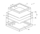
第1実施形態のエアフィルタの分解斜視図である。It is a disassembled perspective view of the air filter of 1st Embodiment. 図1のA−A線断面を合わせて示す外枠の要部斜視図である。It is a principal part perspective view of the outer frame which matches and shows the AA line cross section of FIG. 図1のB−B線断面を合わせて示す内枠の要部斜視図である。It is a principal part perspective view of the inner frame which matches and shows the BB line cross section of FIG. 押付状態で内枠が外枠に係止された状態を示す要部斜視図である。It is a principal part perspective view which shows the state by which the inner frame was latched by the outer frame in the pressing state. エアフィルタにおける虫の侵入経路を説明する要部断面図である。It is principal part sectional drawing explaining the insect penetration | invasion path | route in an air filter. 第2実施形態のエアフィルタの分解斜視図である。It is a disassembled perspective view of the air filter of 2nd Embodiment. 図6のエアフィルタの組み立て方の一例を説明する斜視図である。It is a perspective view explaining an example of the assembly method of the air filter of FIG. エアフィルタの断面として、図6に示す外枠のC−C線断面および内枠のC’−C’線断面を合わせて示す図である。FIG. 7 is a view showing a cross section of the outer frame shown in FIG. 6 taken along the line C-C and a cross section taken along the line C′-C ′ of the inner frame as a cross section of the air filter. エアフィルタの断面として、図6に示すD−D線断面および内枠のD’−D’線断面を合わせて示す図である。FIG. 7 is a view showing a cross section taken along line DD shown in FIG. 6 and a cross section taken along line D′-D ′ shown in FIG. エアフィルタの断面として、図6に示す外枠のE−E線断面および内枠のE’−E’線断面を合わせて示す図である。FIG. 7 is a diagram showing a cross section of the outer frame shown in FIG. 6 taken along the line E-E and a cross section taken along the line E′-E ′ of the inner frame as a cross section of the air filter. 内枠の変形例をZ方向に見て示す側面図である。It is a side view which shows the modification of an inner frame seeing to a Z direction.

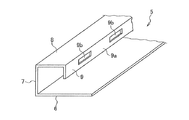
以下、本発明のエアフィルタについて詳細に説明する。
図1に、第1実施形態のエアフィルタ1の分解斜視図を示す。
エアフィルタ1は、フィルタ用濾材(以降、濾材という)3と、防虫網4と、外枠5と、内枠11と、を備える。濾材3は、気体中の微粒子を捕集するためのものである。防虫網4は、虫が通過するのを防止するシート状の部材である。外枠5は、濾材3および防虫網4を外周側から取り囲む矩形(以降の説明において正方形を含む)形状の部材であり、気体が濾材3を通過するよう開口された開口部10を有している。内枠11は、外枠5の開口部10の内側に配置される矩形形状の部材であり、後述する押付部および係止部を有している。なお、図1において、外枠5の孔(後述)および内枠11の係止部(後述)は図示を省略している。
Hereinafter, the air filter of the present invention will be described in detail.
FIG. 1 is an exploded perspective view of the air filter 1 of the first embodiment.
The air filter 1 includes a filter medium (hereinafter referred to as a filter medium) 3, an insect screen 4, an outer frame 5, and an inner frame 11. The filter medium 3 is for collecting fine particles in the gas. The insect net 4 is a sheet-like member that prevents insects from passing through. The outer frame 5 is a rectangular (including a square in the following description) shape that surrounds the filter medium 3 and the insect screen 4 from the outer peripheral side, and has an opening 10 that is opened so that gas passes through the filter medium 3. Yes. The inner frame 11 is a rectangular member disposed inside the opening 10 of the outer frame 5 and has a pressing portion and a locking portion described later. In FIG. 1, a hole (described later) of the outer frame 5 and a locking portion (described later) of the inner frame 11 are not shown.

(濾材)
濾材3は、例えば、粒径5μm以上、濃度0.4〜7mg/mの粉塵の除去に用いられるプレフィルタ用濾材である。プレフィルタ用濾材としては、捕集効率が、質量法で70〜90%、計数法で5〜10%のいずれかであって、圧力損失が20〜196Pa、粉塵保持容量が300〜2000g/mであるものが用いられる。捕集効率の測定に際して、質量法では、JIS Z8901に規定される15種の粉体、又は、米国暖房冷凍空調学会(ASHRAE)に規定される粉塵が用いられる。計数法では、粒径0.3μmの、大気塵、ポリアルファオレフィン(PAO)、シリカのいずれかの粒子が用いられる。粉塵保持容量は、濾材が所定の最終圧力損失に達するまでに捕集した粉塵量である。
(Filter material)
The filter medium 3 is, for example, a prefilter filter medium used for removing dust having a particle diameter of 5 μm or more and a concentration of 0.4 to 7 mg / m 3 . As a filter material for prefilter, the collection efficiency is either 70 to 90% by mass method or 5 to 10% by counting method, pressure loss is 20 to 196 Pa, and dust holding capacity is 300 to 2000 g / m. 3 is used. In measuring the collection efficiency, in the mass method, 15 kinds of powders defined in JIS Z8901 or dusts defined in the American Society of Heating, Refrigerating and Air-Conditioning (ASHRAE) are used. In the counting method, particles of atmospheric dust, polyalphaolefin (PAO), or silica having a particle diameter of 0.3 μm are used. The dust holding capacity is the amount of dust collected until the filter medium reaches a predetermined final pressure loss.

濾材3の性能は、上記したものに制限されず、中性能フィルタ、準HEPAフィルタ、HEPAフィルタ、ULPAフィルタ等のいずれかであってもよい。ULPA(Ultra Low Penetration Air)フィルタは、定格風量で粒径0.15μmの粒子に対して99.9995%以上の捕集効率を有し、かつ初期の圧力損失が245Pa以下であるフィルタである。HEPA(High Efficiency Particulate Air)フィルタは、定格風量で粒径0.3μmの粒子に対して99.97%以上の捕集効率を有し、かつ初期の圧力損失が245Pa以下であるフィルタである。準HEPAフィルタは、例えば、粒径0.3μmの粒子に対して90%程度以上99.97%未満の捕集効率を有するフィルタである。中性能フィルタは、主として粒径が5μmより小さい粒子に対して中程度の粒子捕集率をもつフィルタである。   The performance of the filter medium 3 is not limited to those described above, and may be any of a medium performance filter, a semi-HEPA filter, a HEPA filter, a ULPA filter, and the like. The ULPA (Ultra Low Penetration Air) filter is a filter having a collection efficiency of 99.9995% or more with respect to particles having a rated air volume of 0.15 μm in diameter and an initial pressure loss of 245 Pa or less. The HEPA (High Efficiency Particulate Air) filter is a filter having a trapping efficiency of 99.97% or more with respect to particles having a rated air volume of 0.3 μm in diameter and an initial pressure loss of 245 Pa or less. The quasi-HEPA filter is, for example, a filter having a collection efficiency of about 90% or more and less than 99.97% with respect to particles having a particle diameter of 0.3 μm. The medium performance filter is a filter having a medium particle collection rate mainly for particles having a particle size of less than 5 μm.

プレフィルタ用濾材には、具体的に、ガラス繊維(湿式不織布、長繊維、短繊維)または合成繊維を繊維材料とする、マット状、フェルト状の濾材が用いられる。プレフィルタ用濾材には、例えば、スパンボンド、メルトブロー、サーマルボンド、ケミカルボンドによって製造されたものを用いることができる。このようなプレフィルタ用濾材は、厚み方向に圧縮されることができる。プレフィルタ用濾材は、濾材本来の捕集性能に、濾材の繊維が帯電することによる捕集性能を付与するために、エレクトレット処理が施されたものであってもよい。また、プレフィルタ用濾材は、抗菌性能を付与するために、濾材に抗菌剤を付着させる抗菌処理が施されたものであってもよい。エレクトレット処理および抗菌処理は、組み合わせて施されていてもよい。
濾材3は、厚み方向に、一層で構成されたものであってもよく、複数の層で構成されたものであってもよい。複数の層で構成された濾材3として、例えば、後述する、複数の濾材シートを有する濾材が挙げられる。複数の層は、互いに、同じ種類の繊維材料で構成されたものであってもよく、異なる種類の繊維材料で構成されたものであってもよい。
Specifically, a mat-like or felt-like filter medium using glass fiber (wet non-woven fabric, long fiber, short fiber) or synthetic fiber as the fiber material is used as the prefilter filter medium. As the filter material for the prefilter, for example, one produced by spun bond, melt blow, thermal bond, or chemical bond can be used. Such a filter material for prefilters can be compressed in the thickness direction. The filter material for a prefilter may be subjected to electret treatment in order to impart collection performance due to charging of the filter medium fibers to the original collection performance of the filter medium. Further, the prefilter filter medium may be subjected to antibacterial treatment for attaching an antibacterial agent to the filter medium in order to impart antibacterial performance. The electret treatment and the antibacterial treatment may be performed in combination.
The filter medium 3 may be composed of one layer in the thickness direction, or may be composed of a plurality of layers. Examples of the filter medium 3 composed of a plurality of layers include a filter medium having a plurality of filter medium sheets, which will be described later. The plurality of layers may be composed of the same type of fiber material, or may be composed of different types of fiber material.

濾材3の厚みは、外枠5の気流方向の長さ(高さ)や求められる濾材3の捕集性能、フィルタ寿命を考慮して定めることができ、プレフィルタ用濾材として用いる場合、例えば、5〜20mmである。また、濾材3の厚みは、この範囲に制限されず、例えば、0mmを超え、5mm以下であってもよく、20mmを超えていてもよい。濾材3の厚みは、後述するように防虫網4の気流方向の両側に分けて複数の濾材シートが配される場合は、濾材シートの厚みの合計量をいう。また、濾材3の目付は、求められる濾材3の捕集性能、フィルタ寿命を考慮して定めることができ、プレフィルタ用濾材として用いる場合は、例えば100〜800g/mである。また、濾材3の繊維径は、求められる濾材3の捕集性能を考慮して調整でき、プレフィルタ用濾材として用いる場合は、例えば、30〜60μmである。 The thickness of the filter medium 3 can be determined in consideration of the length (height) of the outer frame 5 in the airflow direction, the required collection performance of the filter medium 3, and the filter life. When used as a filter medium for a prefilter, for example, 5 to 20 mm. Further, the thickness of the filter medium 3 is not limited to this range, and may be, for example, more than 0 mm, 5 mm or less, or more than 20 mm. As will be described later, the thickness of the filter medium 3 refers to the total thickness of the filter medium sheets when a plurality of filter medium sheets are arranged on both sides of the insect net 4 in the airflow direction. Further, the basis weight of the filter medium 3 can be determined in consideration of the required collection performance of the filter medium 3 and the filter life. When used as a prefilter filter medium, it is, for example, 100 to 800 g / m 2 . Moreover, the fiber diameter of the filter medium 3 can be adjusted in consideration of the required collection performance of the filter medium 3, and is 30 to 60 μm, for example, when used as a filter medium for a prefilter.

(防虫網)
エアフィルタ1は、防虫網4を備えることで、濾材3の平面方向の中央領域において、濾材3の繊維構造による抵抗を受けながらも濾材3の中を下流側に移動して通り抜けようとする虫を捕捉することができる。なお、本明細書において、平面方向とは、気流方向と直交する平面が延びる方向を意味し、濾材3の延在方向という場合もある。また、気流方向とは、濾材3を通過する気体の方向を意味し、図1の上下方向、図6および図7のX方向に相当する。また、本明細書において、虫という場合は、特に断った場合を除いて、ミカンキイロアザミウマを意味する。なお、エアフィルタ1は、他の種類のアザミウマや、アザミウマ以外の虫の侵入を防止するものとして用いられてもよい。
(Insect screen)
The air filter 1 includes an insect repellent net 4 so that in the central region in the plane direction of the filter medium 3, insects that move through the filter medium 3 while passing through the resistance of the fiber structure of the filter medium 3 to pass through. Can be captured. In the present specification, the plane direction means a direction in which a plane orthogonal to the airflow direction extends, and may be referred to as an extending direction of the filter medium 3. Further, the airflow direction means the direction of gas passing through the filter medium 3, and corresponds to the vertical direction in FIG. 1 and the X direction in FIGS. In addition, in this specification, the term “insect” means mandarin orange thrips unless otherwise specified. The air filter 1 may be used to prevent invasion of other types of thrips and insects other than thrips.

防虫網4には、虫の通過を防止しうるものであればよく、織物又は編物等の網体を使用することができ、また、不織布、エキスパンド、パンチングなど網体以外のものを使用することもできる。織物又は編物が備える平均開孔径の大きさは、特に限定されないが、虫が織物又は編物を通過するのを防止できる大きさであり、かつ、求められる通気抵抗の値に合わせて適宜調整されることが好ましい。具体的には、0.1mm以上1mm未満であることが好ましい。平均開孔径は、例えば、走査型電子顕微鏡(SEM)等を用いて防虫網4の開孔の面積を測定し、同じ面積を有する円の直径を開孔径としたとき、無作為に抽出した防虫網4のn(n=5以上)個の開孔径の平均値をいう。また、開孔率は、防虫性と通風性の観点から、30〜70%であることが好ましい。開孔率は、防虫網の平面方向の面積に占める開孔の面積の合計の割合である。後述する有機材料を繊維材料とする網体を用いる場合の好ましい防虫網4として、例えば、30メッシュのもの、具体的には、平均開孔径が0.77mm、線径φが0.17mm、開孔率が約37%、厚みが0.3mmのものを挙げることができる。
防虫網4を構成する網体の繊維成分は特に限定されず、例えば、ポリオレフィン系樹脂(ポリエチレン、ポリプロピレン、ポリメチルペンテンなど)、スチレン系樹脂、ポリビニルアルコール系樹脂、ポリエーテル系樹脂(ポリエーテルエーテルケトン、ポリアセタール、変性ポリフェニレンエーテル、芳香族ポリエーテルケトンなど)、ポリエステル系樹脂(ポリエチレンテレフタレート、ポリトリメチレンテレフタレート、ポリブチレンテレフタレート、ポリエチレンナフタレート、ポリブチレンナフタレート、ポリカーボネート、ポリアリレート、全芳香族ポリエステル樹脂など)、ポリイミド系樹脂、ポリアミドイミド樹脂、ポリアミド系樹脂(例えば、芳香族ポリアミド樹脂、芳香族ポリエーテルアミド樹脂、ナイロン樹脂など)、ニトリル基を有する樹脂(例えば、ポリアクリロニトリルなど)、ウレタン系樹脂、エポキシ系樹脂、ポリスルホン系樹脂(ポリスルホン、ポリエーテルスルホンなど)、フッ素系樹脂(ポリテトラフルオロエチレン、ポリフッ化ビニリデンなど)、セルロース系樹脂、ポリベンゾイミダゾール樹脂などの公知の有機ポリマー、金属アルコキシド(ケイ素、アルミニウム、チタン、ジルコニウム、ホウ素、スズ、亜鉛などのメトキシド、エトキシド、プロポキシド、ブトキシドなど)が重合した無機ポリマーなどの公知の無機系化合物が重合してなるポリマー、あるいは、金属、ガラスなど無機材料を用いることができる。
The insect repellent net 4 is not limited as long as it can prevent the passage of insects, and a net body such as a woven fabric or a knitted fabric can be used. You can also. The size of the average pore diameter of the woven fabric or the knitted fabric is not particularly limited, but is a size capable of preventing insects from passing through the woven fabric or the knitted fabric, and is appropriately adjusted according to the required value of ventilation resistance. It is preferable. Specifically, it is preferably 0.1 mm or more and less than 1 mm. The average aperture diameter is, for example, an insect repellent randomly extracted when the aperture area of the insect screen 4 is measured using a scanning electron microscope (SEM) or the like, and the diameter of a circle having the same area is defined as the aperture diameter. The average value of n (n = 5 or more) hole diameters of the mesh 4 is said. Moreover, it is preferable that a hole area rate is 30 to 70% from a viewpoint of insect repellent and ventilation. The hole area ratio is a ratio of the total area of the holes in the area in the plane direction of the insect screen. As a preferable insect repellent net 4 in the case of using a net made of an organic material, which will be described later, as a fiber material, for example, a 30-mesh net, specifically, an average hole diameter of 0.77 mm, a wire diameter φ of 0.17 mm, Examples thereof include a porosity of about 37% and a thickness of 0.3 mm.
The fiber component of the net constituting the insect screen 4 is not particularly limited. For example, polyolefin resin (polyethylene, polypropylene, polymethylpentene, etc.), styrene resin, polyvinyl alcohol resin, polyether resin (polyether ether). Ketone, polyacetal, modified polyphenylene ether, aromatic polyether ketone, etc.), polyester resin (polyethylene terephthalate, polytrimethylene terephthalate, polybutylene terephthalate, polyethylene naphthalate, polybutylene naphthalate, polycarbonate, polyarylate, wholly aromatic polyester Resin), polyimide resin, polyamideimide resin, polyamide resin (for example, aromatic polyamide resin, aromatic polyetheramide resin, nylon resin, etc.) Resin having nitrile group (eg, polyacrylonitrile), urethane resin, epoxy resin, polysulfone resin (polysulfone, polyethersulfone, etc.), fluorine resin (polytetrafluoroethylene, polyvinylidene fluoride, etc.), cellulose Resins, known organic polymers such as polybenzimidazole resins, known inorganic polymers such as metal alkoxides (methoxides such as silicon, aluminum, titanium, zirconium, boron, tin, and zinc, ethoxide, propoxide, butoxide) A polymer obtained by polymerizing an inorganic compound, or an inorganic material such as metal or glass can be used.

防虫網4は、濾材3の延在方向に沿ってかつ濾材3の厚み方向の両端の間の中央領域に位置するよう配置されていることが好ましい。この理由は、防虫網4が、外枠5の外側において開口部10を覆うように配され、防虫網4の外周側の端部が外枠5に接着等されている場合、防虫網4の外周側の端部が外枠5から剥がれやすいために、防虫網4と外枠5との間に隙間ができて虫が侵入する恐れがあるためである。防虫網4を濾材3の中央領域に配置する場合、濾材3は、例えば、第1の濾材シート3a(第1の濾材要素)および第2の濾材シート3b(第2の濾材要素)を有し、防虫網4は、第1の濾材シート3aおよび第2の濾材シート3bの間に挿入される。第1の濾材シート3aおよび第2の濾材シート3bは、それぞれ予め形成されたものを好ましく用いることができる。上記のように、防虫網4の上流側(第1の側)に第1の濾材シート3aが配されていることで、内枠11の押付部が防虫網4に直接接触して防虫網4の網目を広げてしまうのを抑えることができ、さらに、防虫網4の下流側(第2の側)に第2の濾材シート3bが配されていることで、防虫網4の下流側においても気体中の塵埃を捕集し、特に、防虫網4によって捕捉された虫の糞や死骸の分解物によって汚染された気体がエアフィルタ1の下流側に流出するのを抑えることができる。このような観点からは、第1の濾材シート3aの厚みが第2の濾材シート3bの厚みよりも小さいことが好ましい。この理由は、組み立てられたエアフィルタ1において、後述する内枠11(押付部)の先端と外枠5の壁部6(第1の壁部)との間の気流方向の距離には限りがあり、濾材3の厚みが制限される一方で、防虫網4の下流側において気体中の塵埃を十分に捕集することが望ましいためである。第1の濾材シート3aは厚みが小さくても、内枠11と防虫網4が直接接触するのを回避する緩衝材としての役割を果たせると考えられ、第1の濾材シート3aの材質や厚み等は、緩衝材としての機能を確保する観点からも調整することができる。なお、第1の濾材シート3aおよび第2の濾材シート3bは、同じ種類のものを用いることができるが、異なる種類のものを用いてもよい。   It is preferable that the insect repellent net 4 is disposed so as to be located in the central region between both ends in the thickness direction of the filter medium 3 along the extending direction of the filter medium 3. The reason for this is that when the insect net 4 is arranged so as to cover the opening 10 outside the outer frame 5, and the outer peripheral end of the insect net 4 is bonded to the outer frame 5, etc. This is because the end on the outer peripheral side is easily peeled off from the outer frame 5, and there is a possibility that a worm may invade due to a gap between the insect screen 4 and the outer frame 5. When the insect net 4 is disposed in the central region of the filter medium 3, the filter medium 3 includes, for example, a first filter medium sheet 3a (first filter medium element) and a second filter medium sheet 3b (second filter medium element). The insect net 4 is inserted between the first filter medium sheet 3a and the second filter medium sheet 3b. As the first filter medium sheet 3a and the second filter medium sheet 3b, those formed in advance can be preferably used. As described above, the first filter medium sheet 3a is arranged on the upstream side (first side) of the insect screen 4 so that the pressing portion of the inner frame 11 directly contacts the insect screen 4 and the insect screen 4 In addition, the second filter medium sheet 3b is disposed on the downstream side (second side) of the insect repellent net 4, so that the downstream of the insect repellent net 4 is also provided. It is possible to collect dust in the gas, and in particular, it is possible to prevent the gas contaminated by insect feces and dead carcasses captured by the insect screen 4 from flowing out to the downstream side of the air filter 1. From such a viewpoint, it is preferable that the thickness of the first filter medium sheet 3a is smaller than the thickness of the second filter medium sheet 3b. This is because the assembled air filter 1 is limited in the distance in the airflow direction between the tip of an inner frame 11 (pressing portion) described later and the wall portion 6 (first wall portion) of the outer frame 5. This is because, while the thickness of the filter medium 3 is limited, it is desirable to sufficiently collect dust in the gas on the downstream side of the insect screen 4. Even if the thickness of the first filter medium sheet 3a is small, it is considered that the first filter medium sheet 3a can play a role as a cushioning material to avoid direct contact between the inner frame 11 and the insect net 4, and the material and thickness of the first filter medium sheet 3a. Can also be adjusted from the viewpoint of securing the function as a cushioning material. The first filter medium sheet 3a and the second filter medium sheet 3b may be the same type, but may be different types.

第1の濾材シート3a、防虫網4、および第2の濾材シート3bは、外周側の端部同士が接続されていることが好ましい。これにより、これらの部材3a、4、3bが平面方向に互いにずれるのを抑えられるとともに、これらの部材3a、4、3bを一体として取り扱えることで、濾材3および防虫網4の交換時の取り付け等の作業を容易に行うことができる。これらの部材3a、4、3bの接続位置は、押付部によって押し付けられる濾材3の部分と、濾材3の外周側の端との間の位置であることが好ましい。第1の濾材シート3a、防虫網4、および第2の濾材シート3bの外周側の端部同士の接続は、例えば、これらを縫い合わせることで行うことができる。縫い方は、特に制限されず、例えば、並縫い、返し縫い、星止め等が用いられるが、虫の侵入経路を断つ観点から、返し縫いが好ましい。これらの部材3a、4、3bの接続位置は、内枠11の押付部が当接する位置よりも外周側であることが好ましい。
また、第1の濾材シート3a、防虫網4、および第2の濾材シート3bのうち、第1の濾材シート3aを除いた、防虫網4および第2の濾材シート3bの外周部の端部同士が接続されていることも好ましい。この場合、防虫網4および第2の濾材シート3bが平面方向に互いにずれるのを抑えられるとともに、これらの部材4,3bを一体として取り扱えることで、濾材3および防虫網4の交換時の取り付け等の作業を容易に行うことができる。また、第1の濾材シート3aを、防虫網4および第2の濾材シート3bと別に取り出して、第1の濾材シート3aの洗浄等、防虫網4または防虫網4よりも上流側で捕捉された虫を除去する作業を簡単に行うことができる。
The first filter medium sheet 3a, the insect screen 4 and the second filter medium sheet 3b are preferably connected at the outer ends. Accordingly, the members 3a, 4 and 3b can be prevented from being displaced from each other in the plane direction, and the members 3a, 4 and 3b can be handled as a unit so that the filter medium 3 and the insect net 4 can be attached at the time of replacement. Can be easily performed. The connection position of these members 3a, 4 and 3b is preferably a position between the portion of the filter medium 3 pressed by the pressing portion and the outer peripheral side end of the filter medium 3. The connection of the edge parts of the outer peripheral side of the 1st filter medium sheet | seat 3a, the insect screen 4, and the 2nd filter medium sheet | seat 3b can be performed by sewing these, for example. The method of sewing is not particularly limited, and for example, parallel stitching, reverse stitching, star fixing, or the like is used, but reverse stitching is preferable from the viewpoint of cutting the insect invasion route. The connection position of these members 3a, 4 and 3b is preferably on the outer peripheral side of the position where the pressing portion of the inner frame 11 abuts.
In addition, the ends of the outer peripheries of the insect screen 4 and the second filter material sheet 3b except for the first filter material sheet 3a among the first filter material sheet 3a, the insect screen 4 and the second filter media sheet 3b. Are also preferably connected. In this case, the insect screen 4 and the second filter medium sheet 3b can be prevented from being displaced from each other in the plane direction, and these members 4 and 3b can be handled as a unit so that the filter medium 3 and the insect screen 4 can be attached at the time of replacement. Can be easily performed. Further, the first filter medium sheet 3a was taken out separately from the insect screen 4 and the second filter medium sheet 3b, and was captured upstream of the insect screen 4 or the insect screen 4 such as washing of the first filter sheet 3a. The operation of removing insects can be easily performed.

(外枠)
外枠5は、例えば、矩形形状の各辺を構成する4本の枠材を組み合わせて作製され、枠材の長手方向の端部同士が接合されている。枠材は、例えば、亜鉛鉄板、ステンレス板、アルミニウム板等の金属材料や、樹脂材料からなる。アルミニウム板からなる外枠5は、4本の枠材が一体に成型されたものであってもよい。外枠5は、例えば、所定の外形形状に裁断された一枚の平板を折り曲げる等して作製することができる。
外枠5は、図2に示されるように、壁部6、壁部7、壁部8、および壁部9を有しており、これらの壁部6〜9が幅方向(短手方向)に直列に並んで接続された形状を有している。図2は、図1のA−A線断面を合わせて示す外枠5の要部斜視図である。各壁部6〜9は、外枠5の矩形形状をなす各辺において長辺方向に延びる板状の部分である。各壁部6〜9は、隣接する壁部との接続箇所が図2の断面において直角をなしている。
(Outer frame)
The outer frame 5 is produced, for example, by combining four frame members constituting each side of a rectangular shape, and ends in the longitudinal direction of the frame members are joined. A frame material consists of metal materials, such as a zinc iron plate, a stainless steel plate, and an aluminum plate, and a resin material, for example. The outer frame 5 made of an aluminum plate may be formed by integrally molding four frame members. The outer frame 5 can be produced, for example, by bending a single flat plate cut into a predetermined outer shape.
As shown in FIG. 2, the outer frame 5 has a wall portion 6, a wall portion 7, a wall portion 8, and a wall portion 9, and these wall portions 6 to 9 are in the width direction (short direction). And connected in series. FIG. 2 is a perspective view of a main part of the outer frame 5 shown along the AA line cross section of FIG. Each wall part 6-9 is a plate-shaped part extended in a long side direction in each edge | side which makes the rectangular shape of the outer frame 5. As shown in FIG. Each of the wall portions 6 to 9 is connected at a right angle in the cross section of FIG.

壁部6は、気流方向の下流側(第1の側)から濾材3の外周側の端部(外周部)を支持する部分(第1の壁部)である。壁部6は、内枠11の押付部(後述する壁部12)の先端と気流方向に向かい合う平面方向位置を含む領域に配置され、濾材3および防虫網4を介した内枠5による下流側への圧接力を受ける。また、壁部6は、開口部10の下流側の端をなしている。
なお、壁部6には、内枠11によって押し付けられ厚み方向に圧縮された濾材3の部分を、さらに平面方向に圧縮させうるリブ(不図示)を有していてもよい。そのようなリブは、具体的に、内枠11の押付部12と対向する外枠5の壁部6の位置に、平面方向に互いに離れた2箇所において、壁部6の長辺方向に沿って延びるよう形成される。リブの高さは、濾材3の材質や厚みを考慮して定められる。リブは、壁部6に取り付けられる別の部材に形成されたものであってもよく、壁部6を構成する枠材に形成されたものであってもよい。
壁部7は、濾材3の外周側の端と向かい合う部分であり、気流方向に延びる部分である。
壁部8は、濾材3の外周部の上流側(第2の側)の端と向かい合う部分である。
The wall portion 6 is a portion (first wall portion) that supports an end portion (outer peripheral portion) on the outer peripheral side of the filter medium 3 from the downstream side (first side) in the airflow direction. The wall portion 6 is disposed in a region including a planar position facing the tip of the pressing portion (wall portion 12 described later) of the inner frame 11 in the airflow direction, and is downstream of the inner frame 5 via the filter medium 3 and the insect net 4. It receives pressure contact force. The wall portion 6 forms an end on the downstream side of the opening portion 10.
The wall 6 may have a rib (not shown) that can further compress the portion of the filter medium 3 pressed by the inner frame 11 and compressed in the thickness direction in the plane direction. Specifically, such ribs extend along the long side direction of the wall portion 6 at two positions separated from each other in the plane direction at the position of the wall portion 6 of the outer frame 5 facing the pressing portion 12 of the inner frame 11. Formed to extend. The height of the rib is determined in consideration of the material and thickness of the filter medium 3. The rib may be formed on another member attached to the wall portion 6, or may be formed on a frame material constituting the wall portion 6.
The wall portion 7 is a portion facing the end on the outer peripheral side of the filter medium 3 and is a portion extending in the airflow direction.
The wall portion 8 is a portion facing the upstream end (second side) of the outer peripheral portion of the filter medium 3.

壁部9は、開口部10の上流側の端をなす部分であり、エアフィルタ1の平面方向に沿った開口部10の内側(以降、開口部10の内側という)の空間と接する壁面9aと、内枠11の後述する留め金具の突状部が入り込む孔9bと、を有している。孔9bは、例えば、外枠5の各辺において2つ設けられるが、2つに限定されず、内枠11の各辺における係止部の数に応じて、1つ、または、3つ以上設けられてもよい。孔9bが各辺において複数設けられる場合、孔9bは、各壁部9を長辺方向に同じ長さずつ複数に分割した領域に1つずつ設けられることが好ましい。孔9bが各辺において1つ設けられる場合は、各壁部9の長辺方向の中間点に設けられることが好ましい。
孔9bは、上記突状部が入り込んだ状態で、内枠11の上流側の端が外枠5の上流側の端(壁部8の上流側の表面)より上流側に位置しないことが好ましい。内枠11の上流側の端が外枠5の上流側の端と同じ気流方向位置または下流側に位置することにより、エアフィルタ1を、例えばダクトの途中のケーシングに取り付けたときに、エアフィルタ1の気流方向の端を受けるケーシングの部分(不図示)に内枠11が当たって、ケーシングと外枠5との間のリークを発生させる隙間ができるのを抑えることができる。
The wall portion 9 is a portion that forms an upstream end of the opening portion 10, and a wall surface 9 a that is in contact with the space inside the opening portion 10 (hereinafter referred to as the inside of the opening portion 10) along the planar direction of the air filter 1. And a hole 9b into which a protruding portion of a fastener described later of the inner frame 11 enters. For example, two holes 9 b are provided on each side of the outer frame 5, but the number is not limited to two. One or three or more holes 9 b are provided depending on the number of locking portions on each side of the inner frame 11. It may be provided. In the case where a plurality of holes 9b are provided on each side, it is preferable that one hole 9b be provided in each of the regions obtained by dividing each wall portion 9 into a plurality of the same length in the long side direction. When one hole 9b is provided on each side, it is preferable that the hole 9b is provided at an intermediate point in the long side direction of each wall portion 9.
In the hole 9b, it is preferable that the upstream end of the inner frame 11 is not positioned upstream of the upstream end of the outer frame 5 (the upstream surface of the wall portion 8) in a state where the protruding portion is inserted. . When the upstream end of the inner frame 11 is located at the same airflow direction position or downstream side as the upstream end of the outer frame 5, the air filter 1 is attached to a casing in the middle of the duct, for example. It is possible to prevent the inner frame 11 from hitting a portion (not shown) of the casing that receives the end in the airflow direction of 1 and forming a gap that generates a leak between the casing and the outer frame 5.

(内枠)
内枠11は、外枠5の壁部9に沿って周状に形成された一体の部材である。内枠11は、開口部10の内側に配置された状態で、壁部9との間に平面方向に僅かな隙間(数mm)があく程度の外形を有していることが好ましい。これにより、内枠11を、開口部10内に容易に配置することができ、かつ、内枠11を外枠5に対して平面方向に位置決めしやすくなる。内枠11は、例えば、所定の外形をなすよう裁断加工された一枚の平板を用いて作製することができる。所定の外形は、矩形形状の四辺に対応する4つの押付部12(後述)となる部分が長辺方向に直列に接続され、かつ、これらの部分のそれぞれに、4つの壁部13(後述)となる部分のうちの1つが短手方向に接続された形状である。このような外形を有する一枚の平板を、押付部12同士の接続箇所で折り曲げて矩形形状にして、上記一枚の平板の長辺方向の両端同士をリベットにより接続するとともに、開口部10の上流側の端を形成するように、壁部13となる部分を押付部12に対して折り曲げることにより、周方向に隙間のない一体の部材を作製することができる。一枚の平板において、壁部13となる部分は、長辺方向の両端が、長辺方向に対し45°傾斜して面取り(角落とし)されるよう、裁断加工されている。具体的に、一枚の平板において、壁部13となる部分は、押付部12に接続された位置を底辺とし、押付部12から最も離れた端を上辺とする台形形状をなしている。これにより、壁部13となる部分を押付部12に対して折り曲げたときに、隣接する壁部13同士が厚み方向に重なることなくかつ隙間なく当接することができる。枠材は、例えば、亜鉛鉄板、ステンレス板、アルミニウム板等の金属材料や、樹脂材料からなる。アルミニウム板からなる外枠5は、4本の枠材が一体に成型されたものであってもよい。
なお、内枠11は、開口部10をなす外枠5の端に沿って周状に形成されたものであれば特に制限されず、例えば、4本の枠材が虫が通過しない程度の大きさの隙間(例えば0.1〜1.0mm)をあけて配置されたものであってもよい。この場合、直交するように接続される枠材の端部同士は、例えば、断面略L字状の金具を用いて互いに接続される。
(The inner frame)
The inner frame 11 is an integral member formed in a circumferential shape along the wall portion 9 of the outer frame 5. The inner frame 11 preferably has an outer shape with a slight gap (several mm) in the plane direction between the inner frame 11 and the wall 9 in a state where the inner frame 11 is disposed inside the opening 10. Thereby, the inner frame 11 can be easily arranged in the opening 10, and the inner frame 11 can be easily positioned with respect to the outer frame 5 in the planar direction. The inner frame 11 can be produced using, for example, a single flat plate cut to have a predetermined outer shape. The predetermined outer shape is such that four pressing portions 12 (described later) corresponding to the four sides of the rectangular shape are connected in series in the long side direction, and four wall portions 13 (described later) are connected to each of these portions. One of the portions is a shape connected in the short direction. A single flat plate having such an outer shape is bent at a connection portion between the pressing portions 12 to form a rectangular shape, and both ends in the long side direction of the single flat plate are connected to each other by rivets. By bending the portion that becomes the wall portion 13 with respect to the pressing portion 12 so as to form the upstream end, an integral member having no gap in the circumferential direction can be produced. In one flat plate, the portion that becomes the wall portion 13 is cut so that both ends in the long side direction are chamfered (cornered) at 45 ° with respect to the long side direction. Specifically, in one flat plate, a portion that becomes the wall portion 13 has a trapezoidal shape with a position connected to the pressing portion 12 as a base and an end farthest from the pressing portion 12 as an upper side. Thereby, when the part used as the wall part 13 is bend | folded with respect to the pressing part 12, the adjacent wall parts 13 can contact | abut without overlapping in the thickness direction without gap. A frame material consists of metal materials, such as a zinc iron plate, a stainless steel plate, and an aluminum plate, and a resin material, for example. The outer frame 5 made of an aluminum plate may be formed by integrally molding four frame members.
The inner frame 11 is not particularly limited as long as it is formed in a circumferential shape along the end of the outer frame 5 forming the opening 10. For example, the inner frame 11 is large enough to prevent four frame members from passing through insects. It may be arranged with a gap (for example, 0.1 to 1.0 mm). In this case, the ends of the frame members connected to be orthogonal to each other are connected to each other using, for example, a metal fitting having a substantially L-shaped cross section.

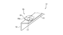
内枠11は、図3に示されるように、壁部12、壁部13、および係止部15を有している。このうち、壁部12は、押付部として機能し、押付部12ともいう。なお、図3は、図1のB−B線断面を合わせて示す内枠11の要部斜視図である。2つの壁部12,13は、それぞれ内枠11の矩形形状をなす各辺において長辺方向に延びる板状の部分である。壁部13は、気流方向に延びる部分である。各壁部12,13は、図3の断面において直角をなすよう接続されている。   As shown in FIG. 3, the inner frame 11 has a wall portion 12, a wall portion 13, and a locking portion 15. Among these, the wall part 12 functions as a pressing part, and is also called the pressing part 12. Note that FIG. 3 is a perspective view of a main part of the inner frame 11 that is shown along a cross section taken along line BB in FIG. The two wall portions 12 and 13 are plate-like portions extending in the long-side direction at each side forming the rectangular shape of the inner frame 11. The wall portion 13 is a portion extending in the airflow direction. Each wall part 12 and 13 is connected so that it may make a right angle in the cross section of FIG.

押付部12は、上流側から濾材3および防虫網4の外周側の端部を、外枠5の壁部6側に押し付けて、押付部12が当接した部分において厚み方向に圧縮させる機能を有している。具体的に、押付部12は、濾材3に周状に当接するよう、外枠5の壁部6側に延びて形成されており、全周にわたって幅方向(気流方向)の長さが等しくなっている。押付部12の上記機能によって、図示される例では、濾材3は、押し付けられた部分の捕集性能が損なわれる程度に押し潰され、エアフィルタ1は押付状態となる。押付状態では、押付部12と濾材3との間に隙間がなく、また、濾材3が押し潰されているため、虫が、例えば、内枠11の平面方向位置の内側から外側に通り抜けることができず、図5に示すように、虫の侵入経路を断つことができる。
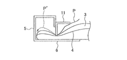
図5は、エアフィルタ1における虫の侵入経路を説明する要部断面図である。エアフィルタ1では、虫が上流側から内枠11の壁部13と濾材3の間のスペースから侵入して、図5の太い実線Pで示す経路に沿って移動することが考えられる。ここで、内枠11を備えない従来のエアフィルタでは、虫は、濾材3の上流側の表面上を濾材3の外周側に移動して濾材3の外周側の端に達した後、濾材3と、外枠5の壁部6との間の隙間、あるいは、濾材3の内部にもぐり込もうとする場合があり、エアフィルタの下流側に通り抜けてしまう可能性がある。第1実施形態のエアフィルタ1では、内枠11によって濾材3を外枠5側に押し付けて圧縮させることで、濾材3の外周側の端からのこのような虫の通り抜けを抑えられることができる。これにより、外枠5内の気流方向の領域において濾材3の外周側の端の近傍に溜まる虫の数を減らし、かつ、濾材3の外周側の端の近傍が外枠5と内枠11に囲まれて外部から見えにくくなっていることで、見る者に不衛生な印象を与えることを抑えることができる。また、第1実施形態のエアフィルタ1では、内枠11によって濾材3を外枠5側に押し付けて圧縮させることで、上流側から実線Pに沿って内枠11の内側(平面方向の内側)から入り込んだ虫の侵入経路を断って、破線P’のように内枠11の外側まで移動することを防止できる。これにより、濾材3の外周側の端から、濾材3と外枠5の壁部6との間の隙間あるいは濾材3の内部にもぐり込もうとする虫そのものを減らすことができる。
なお、押付状態での押付部12の先端12aと外枠5の壁部6との距離は、濾材3の材質や厚みを考慮して定められ、0mmを超え7.0mm以下であることが好ましく、例えば4〜7mmに調整される。また、押付部12の先端12aの端面は、平坦であることが好ましいが、例えば、枠材作製時に形成された加工跡による微小な凹凸を有していることにより、押付状態において濾材3に当接しない領域が一部に形成されていてもよい。
The pressing portion 12 has a function of pressing the end portions on the outer peripheral side of the filter medium 3 and the insect screen 4 from the upstream side to the wall portion 6 side of the outer frame 5 and compressing in the thickness direction at the portion where the pressing portion 12 abuts. Have. Specifically, the pressing portion 12 is formed to extend toward the wall portion 6 side of the outer frame 5 so as to contact the filter medium 3 in a circumferential shape, and the length in the width direction (air flow direction) is equal over the entire circumference. ing. With the above function of the pressing unit 12, in the illustrated example, the filter medium 3 is crushed to such an extent that the collection performance of the pressed part is impaired, and the air filter 1 is in the pressing state. In the pressing state, there is no gap between the pressing portion 12 and the filter medium 3, and the filter medium 3 is crushed, so that, for example, insects may pass from the inside to the outside of the position in the plane direction of the inner frame 11. However, as shown in FIG. 5, the insect invasion route can be cut off.
FIG. 5 is a cross-sectional view of an essential part for explaining an insect intrusion route in the air filter 1. In the air filter 1, it is conceivable that insects enter from the space between the wall portion 13 of the inner frame 11 and the filter medium 3 from the upstream side and move along the path indicated by the thick solid line P in FIG. Here, in the conventional air filter that does not include the inner frame 11, the insect moves to the outer peripheral side of the filter medium 3 on the upstream surface of the filter medium 3 and reaches the outer peripheral end of the filter medium 3. And the gap between the outer frame 5 and the wall portion 6 or the inside of the filter medium 3 may be squeezed, and may pass through the downstream side of the air filter. In the air filter 1 according to the first embodiment, the filter medium 3 is pressed against the outer frame 5 side by the inner frame 11 and compressed, so that the passage of such insects from the outer peripheral end of the filter medium 3 can be suppressed. . This reduces the number of insects that accumulate in the vicinity of the outer peripheral end of the filter medium 3 in the region of the air flow direction in the outer frame 5, and the vicinity of the outer peripheral end of the filter medium 3 becomes the outer frame 5 and the inner frame 11. Surrounding and making it difficult to see from the outside can prevent the viewer from giving an unsanitary impression. Further, in the air filter 1 of the first embodiment, the inner side of the inner frame 11 along the solid line P from the upstream side (the inner side in the planar direction) is compressed by pressing the filter medium 3 toward the outer frame 5 by the inner frame 11. It is possible to prevent the insect entering from the path from being cut off and move to the outside of the inner frame 11 as indicated by a broken line P ′. As a result, the gap between the filter medium 3 and the wall portion 6 of the outer frame 5 or the insect itself trying to get into the filter medium 3 from the outer peripheral end of the filter medium 3 can be reduced.
Note that the distance between the tip 12a of the pressing portion 12 and the wall portion 6 of the outer frame 5 in the pressing state is determined in consideration of the material and thickness of the filter medium 3, and is preferably more than 0 mm and 7.0 mm or less. For example, it is adjusted to 4 to 7 mm. In addition, the end surface of the tip 12a of the pressing portion 12 is preferably flat. For example, the pressing portion 12 has a minute unevenness due to a processing mark formed at the time of manufacturing the frame material. A region that is not in contact may be formed in part.

係止部15は、押付状態で、内枠11が外枠5に対して気流方向に移動しないよう内枠11を外枠5に係止させる機能を有する。具体的に、係止部15は、留め金具16(被操作部材)およびピン17を有している。留め金具16は、ピン17で壁部13の上面(上流側の表面)に取り付けられ、図3の両方向矢印で示すように、例えば手で操作して回動させることができる。留め金具16は、外周部の一部が外側に突出した突状部16aを有している。留め金具16は、押付状態で、突状部16aを外枠5の側に突出するよう回動させられることにより、突状部16aが外枠5の壁部9の孔9b内に入り込んで、内枠11が外枠5に係止される。押付状態では、押し付けられた濾材3が厚み方向に沿って上流側に復元しようとする反発力を内枠11に作用させるが、内枠11は、外枠5に係止されることで濾材3の反発力を受けて外枠5に対して上流側に浮き上がるように移動することを防止できる。係止部15は、内枠11の各辺において、外枠5の孔9bの位置と対応する位置に設けられる。なお、係止部15は、内枠11の上流側の端をなしており、その上流側の端は、外枠5の壁部8の上流側の表面と同じ気流方向の位置、または、壁部8の上流側の表面よりも下流側に位置していることが好ましい。   The locking portion 15 has a function of locking the inner frame 11 to the outer frame 5 so that the inner frame 11 does not move in the airflow direction with respect to the outer frame 5 in the pressed state. Specifically, the locking portion 15 includes a fastener 16 (an operated member) and a pin 17. The fastener 16 is attached to the upper surface (upstream surface) of the wall portion 13 by a pin 17 and can be rotated, for example, by hand, as indicated by a double arrow in FIG. The fastener 16 has a protruding portion 16a in which a part of the outer peripheral portion protrudes outward. In the pressing state, the clasp 16 is rotated so that the projecting portion 16a protrudes toward the outer frame 5, so that the projecting portion 16a enters the hole 9b of the wall portion 9 of the outer frame 5, The inner frame 11 is locked to the outer frame 5. In the pressed state, the pressed filter medium 3 acts on the inner frame 11 with a repulsive force to restore the upstream side along the thickness direction. However, the inner frame 11 is locked to the outer frame 5 so that the filter medium 3 is locked. It is possible to prevent the repelling force from moving so as to float upstream from the outer frame 5. The locking portion 15 is provided at a position corresponding to the position of the hole 9 b of the outer frame 5 on each side of the inner frame 11. The locking portion 15 forms an upstream end of the inner frame 11, and the upstream end of the locking portion 15 has the same position in the airflow direction as the upstream surface of the wall portion 8 of the outer frame 5 or a wall. It is preferable to be located downstream of the upstream surface of the portion 8.

留め金具16と壁部13との間には、例えば、ピン17に挿通されるようにスプリングワッシャ、コイルばね等の付勢部材(不図示)が配されていてもよい。付勢部材によって留め金具16と壁部13が互いに離れるよう付勢されていることによって、押し付けられた濾材3の反発力が、例えば経時的に小さくなった場合であっても、付勢部材が壁部13を押付部12ごと濾材3側に押し付ける力を十分に確保して、押付部12と濾材3の間あるいは濾材3と壁部6との間に隙間ができるのをより確実に防止することできる。
なお、係止部15は、例えば、内枠11の各辺において2つ設けられるが、2つに制限されず、エアフィルタ1の寸法等を考慮して調整でき、1つ、または、3つ以上設けられてもよい。
For example, a biasing member (not shown) such as a spring washer or a coil spring may be disposed between the fastener 16 and the wall portion 13 so as to be inserted into the pin 17. Even when the repulsive force of the pressed filter medium 3 becomes smaller with time due to the biasing member biasing the fastener 16 and the wall 13 away from each other, for example, A sufficient force to press the wall portion 13 together with the pressing portion 12 to the filter medium 3 side is ensured, and a gap is more reliably prevented from being formed between the pressing portion 12 and the filter medium 3 or between the filter medium 3 and the wall portion 6. I can.
Note that, for example, two locking portions 15 are provided on each side of the inner frame 11, but the number of the locking portions 15 is not limited to two, and can be adjusted in consideration of the dimensions of the air filter 1. It may be provided as described above.

エアフィルタ1は、さらに、開口部10において下流側に露出する濾材3の部分を下流側から支持する支持部材(不図示)を備えていてもよい。支持部材としては、例えば、金網等のシート状部材や、開口部10の下流側の対向する端同士を接続するよう設けられたステイ等が挙げられる。シート状部材は、外枠5の壁部6と濾材3との間に配される。シート状部材には、例えば、上述の防虫網4よりも平均開孔径が大きいもの等を用いることができる。ステイは、例えば、複数の棒状部材を、平面方向に略等間隔に並べて配置されたものを用いることができる。ステイは、外枠5の壁部6に接続され、開口部10の下流側の端をなす空間を横切るように設けられる。このような支持部材が備えられることで、押付部12に押し付けられて内枠11の内側から下流側に突出しようとする濾材3に対して、下流側から圧接力を作用させることができる。また、支持部材が備えられることで、気流の速度が大きいこと等によって、濾材3が外枠5から外れて下流側に抜けるのを抑えることができる。   The air filter 1 may further include a support member (not shown) that supports the portion of the filter medium 3 exposed to the downstream side in the opening 10 from the downstream side. Examples of the support member include a sheet-like member such as a wire mesh, a stay provided so as to connect opposite ends on the downstream side of the opening 10, and the like. The sheet-like member is disposed between the wall portion 6 of the outer frame 5 and the filter medium 3. As the sheet-like member, for example, a member having an average aperture diameter larger than that of the above-described insect net 4 can be used. As the stay, for example, a member in which a plurality of rod-like members are arranged at substantially equal intervals in the plane direction can be used. The stay is connected to the wall portion 6 of the outer frame 5 and is provided so as to cross the space forming the downstream end of the opening 10. By providing such a support member, a pressure contact force can be applied from the downstream side to the filter medium 3 that is pressed against the pressing portion 12 and is about to protrude from the inside of the inner frame 11 to the downstream side. Further, by providing the support member, it is possible to prevent the filter medium 3 from coming off the outer frame 5 and coming out to the downstream side due to the high velocity of the airflow.

第1実施形態のエアフィルタ1は、ビル、工場等の建物に設けられたダクトの所定の設置箇所に取り付けることができる。エアフィルタ1の上流側または下流側の端をなす壁部には、ケーシングの取付箇所とエアフィルタ1との間のリークを防ぐためのガスケットを設けることができる。ガスケットは、例えば、発泡ポリウレタン、ゴム等を材質とする。また、ケーシングには、エアフィルタ1と異なる他のエアフィルタが、エアフィルタ1の上流側または下流側に、気流方向に間隔をあけてまたは隣接して配されてもよい。また、エアフィルタ1は、ケーシングの取付箇所に対して、直接設置されてもよく、エアフィルタ1を内部に収容できるボックス状の別のケーシングに収納された状態で間接的に設置されてもよい。   The air filter 1 of 1st Embodiment can be attached to the predetermined installation location of the duct provided in buildings, such as a building and a factory. A gasket for preventing leakage between the attachment location of the casing and the air filter 1 can be provided on the wall portion forming the upstream or downstream end of the air filter 1. The gasket is made of, for example, polyurethane foam or rubber. Further, another air filter different from the air filter 1 may be arranged in the casing on the upstream side or the downstream side of the air filter 1 with an interval in the airflow direction or adjacent thereto. Moreover, the air filter 1 may be directly installed with respect to the attachment location of a casing, and may be indirectly installed in the state accommodated in another box-shaped casing which can accommodate the air filter 1 inside. .

エアフィルタ1としては、下記の仕様、性能を備えるDS−600の型式のエアフィルタに、下記の仕様の防虫網を設けたものを例示できる。
外形寸法:縦(図5の紙面奥行方向)610mm×横(図5の左右方向)610mm×高さ(図5の上下方向)20mm
押付状態での押付部12の先端12aと外枠5の壁部6との距離:5.5mm
押付状態での外枠5と内枠11との間の隙間の平面方向長さ:1mm
濾材:厚さ20mm(防虫網の上流側の厚み7mm、下流側の厚み13mm)、目付360g/m、平均繊維径約45μmのポリエステル樹脂製スパンボンド不織布
捕集効率(質量法):82%(JIS B9908 形式3)
初期圧力損失(処理風量3360m/時間):88Pa
粉塵保持量:約860g/m
防虫網:平均開孔径0.77mm、線径φ0.17mm、平均開孔率37%、厚み0.3mmのポリプロピレン樹脂製の織物
Examples of the air filter 1 include a DS-600 type air filter having the following specifications and performance provided with an insect screen of the following specifications.
External dimensions: Vertical (depth direction in FIG. 5) 610 mm × Horizontal (horizontal direction in FIG. 5) 610 mm × Height (vertical direction in FIG. 5) 20 mm
Distance between the tip 12a of the pressing part 12 and the wall part 6 of the outer frame 5 in the pressing state: 5.5 mm
Planar length of the gap between the outer frame 5 and the inner frame 11 in the pressed state: 1 mm
Filter medium: 20 mm thick (7 mm upstream thickness of insect screen, 13 mm downstream thickness), 360 g / m 2 basis weight, average fiber diameter of about 45 μm polyester resin spunbond nonwoven fabric Collection efficiency (mass method): 82% (JIS B9908 format 3)
Initial pressure loss (processed air volume 3360 m 3 / hour): 88 Pa
Dust holding amount: about 860 g / m 2
Insect repellent: Fabric made of polypropylene resin having an average aperture diameter of 0.77 mm, a wire diameter of 0.17 mm, an average aperture ratio of 37%, and a thickness of 0.3 mm

上記仕様、性能はそれぞれ、例えば下記の測定法により測定される。
(厚さ)
試験サンプルに10mmφで2.5Nの荷重をかけたときの厚さを、ダイヤルシックネスゲージを用いて測定する。
(目付)
試験サンプルから採取した100mm×100mmの試験片の重さを測定し、1m当たりの重さに換算して求める。
(平均繊維径)
試験サンプルの表面を走査型電子顕微鏡(SEM)で撮影した画像上で直交した2本の線を引き、これらの線と交わった繊維の像の太さを繊維径として、500本測定し、これらの算術平均を平均繊維径とする。
Each of the above specifications and performance is measured, for example, by the following measurement method.
(thickness)
The thickness when a load of 2.5 N at 10 mmφ is applied to the test sample is measured using a dial thickness gauge.
(Weight)
The weight of a 100 mm × 100 mm test piece taken from the test sample is measured, and is calculated by converting to the weight per 1 m 2 .
(Average fiber diameter)
Two perpendicular lines are drawn on the image of the surface of the test sample taken with a scanning electron microscope (SEM), and the thickness of the fiber image that intersects these lines is measured as the fiber diameter. Is the average fiber diameter.

(捕集効率)
JIS B9908 形式3に準拠し、タテ型試験装置を用いて、JIS Z8901に規定するJIS11種の粉塵による、試験風速2.5m/秒での捕集効率を測定する。
(Collection efficiency)
In accordance with JIS B 9908 Format 3, the collection efficiency at a test wind speed of 2.5 m / sec is measured with a JIS 11 type dust specified in JIS Z8901 using a vertical test apparatus.

(初期圧力損失)
JIS B9908 形式3に準拠し、610mm×610mmの寸法のダクトを用いて、風速2.5m/秒での圧力損失を測定する。
(粉塵保持量)
JIS B9908 形式3に準拠して、JIS Z8901に規定するJIS11種の粉体による、粉塵濃度70±30mg/m、試験風速2.5m/秒での圧力損失が最終圧力損失(250Pa)に達するまでの粉塵供給量を測定する。
(防虫性能)
エアフィルタ1の試験サンプルを風速2.5m/秒で通風しつつ、上流側からミカンキイロアザミウマの成虫100匹を放って1日後に試験サンプルの下流側に存在する虫の数を数え、放った虫の数に占める試験サンプルによって捕捉された虫の数の割合を計算して捕集率(%)とし、同じ試験を3回行って得られた捕集率の平均値を求め、防虫性能を評価した。ミカンキイロアザミウマは、重要害虫のひとつとされており、重要害虫のなかで体長が小さい。また、飼育性も良いため、本試験に使用した。この試験によって、本発明のエアフィルタの防虫性能が良好であることが確認された。
(Initial pressure loss)
According to JIS B 9908 format 3, pressure loss at a wind speed of 2.5 m / sec is measured using a duct having a size of 610 mm × 610 mm.
(Dust retention)
In accordance with JIS B 9908 Format 3, the pressure loss at a dust concentration of 70 ± 30 mg / m 3 and a test wind speed of 2.5 m / second by the JIS 11 type powder specified in JIS Z8901 reaches the final pressure loss (250 Pa). Measure the amount of dust supply up to.
(Insect repellent performance)
While ventilating the test sample of the air filter 1 at a wind speed of 2.5 m / sec, 100 adults of Citrus thrips were released from the upstream side, and the number of insects existing on the downstream side of the test sample was counted one day later and released. Calculate the ratio of the number of insects captured by the test sample in the number of insects to obtain the collection rate (%), find the average value of the collection rate obtained by performing the same test three times, evaluated. Citrus thrips is regarded as one of the important pests, and its length is short among the important pests. In addition, it was used in this study because of its good breeding ability. By this test, it was confirmed that the insect filter of the air filter of the present invention has a good insecticidal performance.

以上説明したエアフィルタ1では、濾材3の外周部が、外枠5の壁部6と内枠11の押付部12と間に挟まれることで圧縮され押し潰されている。このため、エアフィルタ1の上流側において内枠11の内側に入り込んだ虫の外周側への侵入経路を断って、虫が内枠11よりも外周側に通り抜けるのを防止できる。また、万一エアフィルタ1の上流側において外枠5と内枠11との間の隙間からエアフィルタ1内に虫が入り込み、濾材3の外周側の端から濾材3内に侵入したとしても、内枠11で押し付けられた部分よりも内側に通り抜けることができない。
ここで、エアフィルタ1と異なる他のエアフィルタとして、枠体の上流側の壁部および下流側の壁部が、気体が通過する方向の断面において、濾材に厚み方向に食い込むように、濾材に対し厚み方向に圧接力を作用させる形状に加工されたものを想定する。このエアフィルタでは、圧接力が作用する濾材の部分では反発力が強くなっていることで、濾材は壁部に対して強く押し付けられていると考えられる。しかし、このような枠体を備えたエアフィルタを用いた場合であっても、虫が枠体の上流側の壁部と濾材との境界でもがいているうちに、濾材の内部に入り込んで、さらに、濾材の外周側に向かって移動する場合がある。虫が濾材と、濾材の外周側の端と向かい合う枠体の壁部との隙間に向かって進もうとする理由は、上記した形態の他のエアフィルタでは、濾材に枠体の下流側の壁部が食い込む部分の付近での濾材の密度が高くなっているために、虫は、濾材内を気流の方向の下流側に向かって移動するよりも、濾材の密度がより低い(抵抗の小さい)部分に移動しようとし、さらに、濾材の内部を移動するよりも、濾材の外(濾材と外枠との間の隙間)に出ようとするためと考えられる。このため、虫は、濾材3の外周側の端に達した後、濾材3と、外枠5の壁部6との間の隙間、あるいは、濾材3の内部にもぐり込み、エアフィルタの下流側に通り抜ける可能性がある。これに対し、エアフィルタ1では、濾材3の外周部は、内枠11で押し付けられた位置において濾材3の密度が厚み方向に最大限に高くなるよう押し潰されており、虫の侵入経路が完全に断たれ、虫が侵入し得ない構造になっている。
In the air filter 1 described above, the outer peripheral portion of the filter medium 3 is compressed and crushed by being sandwiched between the wall portion 6 of the outer frame 5 and the pressing portion 12 of the inner frame 11. For this reason, it is possible to prevent the insects that have entered the inside of the inner frame 11 on the upstream side of the air filter 1 from entering the outer peripheral side and prevent the insects from passing through the outer side of the inner frame 11. Moreover, even if an insect enters the air filter 1 from the gap between the outer frame 5 and the inner frame 11 on the upstream side of the air filter 1 and enters the filter medium 3 from the outer peripheral end of the filter medium 3, It is impossible to pass inward from the portion pressed by the inner frame 11.
Here, as another air filter different from the air filter 1, the upstream wall portion and the downstream wall portion of the frame body are inserted into the filter medium so as to bite into the filter medium in the thickness direction in the cross section in the direction in which the gas passes. On the other hand, what is processed into a shape in which a pressing force is applied in the thickness direction is assumed. In this air filter, it is considered that the filter medium is strongly pressed against the wall portion because the repulsive force is strong at the portion of the filter medium on which the pressure contact force acts. However, even when using an air filter equipped with such a frame, while insects are struggling at the boundary between the upstream wall of the frame and the filter medium, they enter the inside of the filter medium, Furthermore, it may move toward the outer peripheral side of the filter medium. The reason why insects try to advance toward the gap between the filter medium and the wall of the frame body facing the outer peripheral end of the filter medium is that, in the other air filters described above, the filter medium has a wall on the downstream side of the frame body. Since the density of the filter medium in the vicinity of the part into which the part bites is higher, the insect has a lower density of the filter medium (less resistance) than moving in the filter medium toward the downstream side in the direction of the airflow. It is thought that it tends to move to a part and, moreover, to go out of the filter medium (a gap between the filter medium and the outer frame) rather than moving inside the filter medium. For this reason, after reaching the end on the outer peripheral side of the filter medium 3, the insect digs into the gap between the filter medium 3 and the wall 6 of the outer frame 5 or the inside of the filter medium 3, and downstream of the air filter. There is a possibility to go through. On the other hand, in the air filter 1, the outer periphery of the filter medium 3 is crushed so that the density of the filter medium 3 is maximized in the thickness direction at the position pressed by the inner frame 11. It is completely cut off and has a structure that insects cannot enter.

また、内枠11が一体の部材であることで、濾材3を外枠5の各辺において均等な力で押し付けることができ、各辺の間で濾材3を押し付ける力の強さにバラつきが生じるのを抑えられるとともに、濾材3の交換時の取り付け、取り外しの作業を容易に行うことができる。さらに、内枠11が濾材3を周状に押し付けられることによって、内枠11の押付部12と濾材3との間が全周にわたって当接し、エアフィルタ1の上流側において内枠11の内側から外側への虫の侵入経路を確実に断つことができる。
また、上記した他のエアフィルタでは、濾材の反発力を利用して濾材を枠体に保持させているが、濾材として、枠体からの圧接力を受けても十分な反発力を生じない材質、形状等のものを用いた場合には、虫は濾材と壁部の隙間から容易に侵入することができる。第1実施形態のエアフィルタ1は、濾材3を圧縮し押し潰すことによって虫の侵入経路を断っているため、十分な反発力を発生させない濾材を用いた場合であっても虫の侵入を確実に防止できる。この点で、濾材選択の自由度が高い。
Further, since the inner frame 11 is an integral member, the filter medium 3 can be pressed with an equal force on each side of the outer frame 5, and the strength of the force pressing the filter medium 3 between the sides varies. In addition, it is possible to easily attach and remove the filter medium 3 at the time of replacement. Furthermore, when the inner frame 11 presses the filter medium 3 in a circumferential shape, the pressing portion 12 of the inner frame 11 and the filter medium 3 come into contact with each other over the entire circumference, and from the inside of the inner frame 11 on the upstream side of the air filter 1. The path of entry of insects to the outside can be cut off reliably.
In addition, in the other air filters described above, the filter medium is held on the frame body by utilizing the repulsive force of the filter medium, but the filter medium is a material that does not generate a sufficient repulsive force even if it receives a pressure contact force from the frame body. In the case of using a shape or the like, insects can easily enter from the gap between the filter medium and the wall. In the air filter 1 of the first embodiment, since the insect entry path is cut off by compressing and crushing the filter medium 3, even when a filter medium that does not generate sufficient repulsive force is used, insect entry is ensured. Can be prevented. In this respect, the degree of freedom in selecting the filter medium is high.

(変形例)
濾材3は、第1の濾材シート3aおよび第2の濾材シート3bは、厚みが同じであってもよく、第1の濾材シート3aの厚みが第2の濾材シート3bの厚みよりも大きくてもよい。
エアフィルタ1は、濾材3を上流側の壁部に下流側から押し付けられるようになっていてもよい。この場合、外枠5は、下流側の壁部が上記壁部8と同様に構成され、上流側の壁部が上記壁部6と同様に構成されるとともに、下流側の壁部に上記壁部9が接続される。また、内枠11は、下流側の壁部として上記壁部13が配置され、係止部15は、この下流側の壁部の下流側に設けられる。この場合、上記支持部材は、下流側に配置されることが好ましい。
(Modification)
In the filter medium 3, the first filter medium sheet 3a and the second filter medium sheet 3b may have the same thickness, or even if the thickness of the first filter medium sheet 3a is larger than the thickness of the second filter medium sheet 3b. Good.
The air filter 1 may be configured to press the filter medium 3 against the upstream wall portion from the downstream side. In this case, the outer frame 5 has a downstream wall portion configured similarly to the wall portion 8, an upstream wall portion configured similar to the wall portion 6, and the downstream wall portion including the wall Unit 9 is connected. The inner frame 11 is provided with the wall portion 13 as a downstream wall portion, and the locking portion 15 is provided on the downstream side of the downstream wall portion. In this case, the support member is preferably disposed on the downstream side.

次に、図6〜11を参照して、第2実施形態のエアフィルタについて説明する。
ここでは、第1実施形態のエアフィルタ1と相違する点に注目して、エアフィルタ21を説明する。
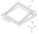
図6は、第2実施形態のエアフィルタ21の分解斜視図である。図7は、エアフィルタ21の組み立て方の一例を説明する斜視図である。図6および図7において、エアフィルタ21の濾材および防虫網の図示は省略されている。図6および図7に示すX方向は、気体が通過する方向である。
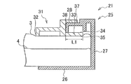
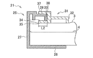
図8は、エアフィルタ21の断面として、図6に示す外枠25のC−C線断面および内枠31のC’−C’線断面を合わせて示す図である。図9は、エアフィルタ21の断面として、図6に示す外枠25のD−D線断面および内枠31のD’−D’線断面を合わせて示す図である。図10は、エアフィルタ21の断面として、図6に示す外枠25のE−E線断面および内枠31のE’−E’線断面を合わせて示す図である。図8〜10において、上方から下方に向かう方向は、図6および図7に示すX方向と一致している。
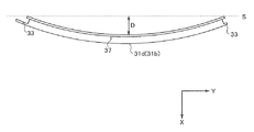
図11は、内枠の変形例をZ方向に見て示す側面図である。
Next, an air filter according to a second embodiment will be described with reference to FIGS.
Here, the air filter 21 will be described by paying attention to differences from the air filter 1 of the first embodiment.
FIG. 6 is an exploded perspective view of the air filter 21 of the second embodiment. FIG. 7 is a perspective view illustrating an example of how to assemble the air filter 21. 6 and 7, the filter medium and the insect net of the air filter 21 are not shown. The X direction shown in FIGS. 6 and 7 is a direction in which gas passes.
FIG. 8 is a view showing a cross section taken along the line CC of the outer frame 25 shown in FIG. 6 and a cross section taken along the line C′-C ′ of the inner frame 31 as a cross section of the air filter 21. FIG. 9 is a diagram showing a cross section taken along line DD of the outer frame 25 and a cross section taken along line D′-D ′ of the inner frame 31 as a cross section of the air filter 21. FIG. 10 is a view showing the cross section of the air filter 21 together with the cross section taken along the line EE of the outer frame 25 and the cross section taken along the line E′-E ′ of the inner frame 31 shown in FIG. 6. 8 to 10, the direction from the upper side to the lower side coincides with the X direction shown in FIGS. 6 and 7.
FIG. 11 is a side view showing a modification of the inner frame as viewed in the Z direction.

エアフィルタ21は、濾材3(図8〜10参照)と、防虫網4(図8〜10参照)と、外枠25と、内枠31と、を備える。このうち、濾材3および防虫網4は、第1実施形態で説明した濾材3および防虫網4と同様である。   The air filter 21 includes a filter medium 3 (see FIGS. 8 to 10), an insect screen 4 (see FIGS. 8 to 10), an outer frame 25, and an inner frame 31. Among these, the filter medium 3 and the insect net 4 are the same as the filter medium 3 and the insect net 4 described in the first embodiment.

外枠25は、壁部26(第1の壁部)、壁部27、および壁部28(第2の壁部)を有している。このうち、壁部28は、壁部27の上流側の端から、平面方向の内側に向かって延在する部分である。壁部28は、図8〜10に示されるように、内枠31の上流側の端部(後述するガイド部37)が外枠25の上流側の端と面一に配置されるよう、ガイド部37を受け入れるための気流方向の段差を有している。図6および図7において、この段差の図示は省略されている。また、壁部28は、平面方向の内側の端において、下流側に延在する板状の壁部29を有している。なお、壁部29に、第1実施形態で説明した孔9bは設けられていない。   The outer frame 25 includes a wall portion 26 (first wall portion), a wall portion 27, and a wall portion 28 (second wall portion). Among these, the wall portion 28 is a portion extending from the upstream end of the wall portion 27 toward the inside in the planar direction. As shown in FIGS. 8 to 10, the wall portion 28 is guided so that the upstream end portion (guide portion 37 described later) of the inner frame 31 is flush with the upstream end of the outer frame 25. It has a step in the airflow direction for receiving the portion 37. In FIG. 6 and FIG. 7, the step is not shown. Moreover, the wall part 28 has the plate-shaped wall part 29 extended in a downstream side in the inner edge of a planar direction. The wall 29 is not provided with the hole 9b described in the first embodiment.

内枠31は、図6に示されるように、内枠31を構成する部材の周上の途中に位置する2つの部分であって、互いに平行に延びる第1の部分31aおよび第2の部分31cを有している。第1の部分31aおよび第2の部分31cは、図6に示す例において、内枠31の矩形形状の四辺と対応する4つの部分のうち、一組の対辺と対応する部分である。第1の部分31aおよび第2の部分31cはそれぞれ、外枠25の側に延在し、押付状態において外枠25の壁部28と壁部26との間に配置される爪部33を有している。また、第1の部分31aおよび第2の部分31cはそれぞれ、爪部33の上流側に配置され、かつ、爪部33と対向して外枠25の側に延在するガイド部37を有している。爪部33およびガイド部37は、図6に示す例において、第1の部分31aおよび第2の部分31cが延びる方向に沿って延在するとともに、平面方向に板状に延在している。これにより、爪部33とガイド部37とのX方向の間には、Z方向に延びる溝状のスペースが形成されている。なお、図6において、爪部33とガイド部37とのX方向間の間隔は、誇張して示されている。また、内枠31は、上流側の端部において、図8〜10に示されるように、ガイド部37の平面方向の内側にX方向の段差が設けられている。図6および図7において、この段差の図示は省略されている。   As shown in FIG. 6, the inner frame 31 is two parts located in the middle of the circumference of the members constituting the inner frame 31, and the first part 31 a and the second part 31 c extending in parallel to each other. have. In the example illustrated in FIG. 6, the first portion 31 a and the second portion 31 c are portions corresponding to a pair of opposite sides among the four portions corresponding to the four rectangular sides of the inner frame 31. Each of the first portion 31a and the second portion 31c has a claw portion 33 that extends toward the outer frame 25 and is disposed between the wall portion 28 and the wall portion 26 of the outer frame 25 in the pressed state. doing. Each of the first portion 31 a and the second portion 31 c has a guide portion 37 that is disposed on the upstream side of the claw portion 33 and extends toward the outer frame 25 so as to face the claw portion 33. ing. In the example shown in FIG. 6, the claw portion 33 and the guide portion 37 extend along the direction in which the first portion 31 a and the second portion 31 c extend, and extend in a plate shape in the planar direction. Thus, a groove-like space extending in the Z direction is formed between the claw portion 33 and the guide portion 37 in the X direction. In FIG. 6, the distance between the claw portion 33 and the guide portion 37 in the X direction is exaggerated. Further, as shown in FIGS. 8 to 10, the inner frame 31 is provided with a step in the X direction on the inner side in the planar direction of the guide portion 37 at the upstream end. In FIG. 6 and FIG. 7, the step is not shown.

爪部33は、具体的に、X方向の下流側の端をなす下面35と、X方向の上流側の端をなす上面34と、を有している。下面35は押付部として機能し、上面34は係止部として機能する。エアフィルタ21において、濾材3は、爪部33の下面35によって下流側に押し付けられることで圧縮され、押付状態とされる。そして、押付状態において、爪部33の上面34が外枠25の壁部28に下流側から当接することで、内枠31は外枠25に係止される。具体的に、上面34は、図8〜10に示される例において、壁部28のうち壁部29の先端(下流側の端)に当接する。
エアフィルタ21は、押付状態において、外枠25の壁部26に対する爪部33の下面35の高さ位置(爪部33と壁部26との間の距離)は、濾材3の厚さ(X方向に沿った長さ)より短い。これにより、濾材3は、押付状態において、爪部33によって外枠25の壁部26側に押し付けられ圧縮されることができる。また、押し付けられた濾材3の厚み方向に沿った反発力によって、爪部33の上面34が外枠25の壁部28に押し付けられることで、内枠31を外枠25に係止させることができる。上記距離は、例えば、濾材3の厚みが20mmである場合に、7mmを超え、18mm以下である。
Specifically, the claw portion 33 has a lower surface 35 that forms an end on the downstream side in the X direction and an upper surface 34 that forms an end on the upstream side in the X direction. The lower surface 35 functions as a pressing portion, and the upper surface 34 functions as a locking portion. In the air filter 21, the filter medium 3 is compressed by being pressed downstream by the lower surface 35 of the claw portion 33, and is in a pressed state. Then, in the pressed state, the inner frame 31 is locked to the outer frame 25 by the upper surface 34 of the claw portion 33 coming into contact with the wall portion 28 of the outer frame 25 from the downstream side. Specifically, in the example illustrated in FIGS. 8 to 10, the upper surface 34 abuts on the tip (downstream end) of the wall 29 of the wall 28.
When the air filter 21 is pressed, the height position of the lower surface 35 of the claw portion 33 with respect to the wall portion 26 of the outer frame 25 (the distance between the claw portion 33 and the wall portion 26) is determined by the thickness (X Shorter than the length along the direction). Thus, the filter medium 3 can be pressed and compressed by the claw 33 against the wall 26 side of the outer frame 25 in the pressed state. Further, the upper surface 34 of the claw portion 33 is pressed against the wall portion 28 of the outer frame 25 by the repulsive force along the thickness direction of the pressed filter medium 3, so that the inner frame 31 can be locked to the outer frame 25. it can. For example, when the thickness of the filter medium 3 is 20 mm, the distance exceeds 7 mm and is 18 mm or less.

エアフィルタ21において、第1の部分31aの爪部33が外枠25の側に延在する長さL1(図8参照)は、第2の部分31cの爪部33が外枠25の側に延在する長さL2(図9参照)よりも長いことが好ましい。L1がL2よりも長いことは、外枠25に係止された内枠31が、外枠25から外れ難いことに寄与する。ここで、エアフィルタ21の組み立て方を説明する。外枠25の壁部26と壁部28との間に濾材3および防虫網4を配置した後、図7に示されるように、内枠31を外枠25に対して少し傾けた状態で、外枠25の壁部28を、内枠31の爪部33とガイド部37との間の溝内に配置する。図7において、内枠31の外枠25に対する傾斜は誇張して示される。そして、爪部33とガイド部37との間の溝底38に、外枠25の壁部28を当接させ、内枠31が外枠25と同じ平面内に配置されるよう、内枠31を第1の部分31aを支点として回動させ、第2の部分31cを開口部10内に配置する。このとき、第1の部分31aおよび第2の部分31cにおいて、爪部33の下面35は、濾材3を下流側に押し付けて圧縮しているとともに(押付状態)、第1の部分31aにおいて、爪部33の上面34は、押し付けられた濾材3の反発力を受けて、外枠25の壁部28に下流側から当接している。次いで、内枠31を、図8に示す状態から、外枠25に対しY方向にスライドさせ、第2の部分31cの溝内に外枠25の壁部28を配置する。このとき、外枠25の壁部28は、図9に示されるように、第2の部分31cの溝底38に当接させてもよい。このとき、第2の部分31cの爪部33の上面34は、濾材3の反発力を受けて外枠25の壁部28に下流側から当接している。このようにして、内枠31は外枠25に係止され、エアフィルタ21は組み立てられる。   In the air filter 21, the length L1 (see FIG. 8) in which the claw portion 33 of the first portion 31a extends to the outer frame 25 side is such that the claw portion 33 of the second portion 31c is on the outer frame 25 side. It is preferable that the length is longer than the extending length L2 (see FIG. 9). The fact that L1 is longer than L2 contributes to the fact that the inner frame 31 locked to the outer frame 25 is difficult to come off from the outer frame 25. Here, how to assemble the air filter 21 will be described. After the filter medium 3 and the insect net 4 are disposed between the wall portion 26 and the wall portion 28 of the outer frame 25, as shown in FIG. 7, the inner frame 31 is slightly inclined with respect to the outer frame 25, The wall portion 28 of the outer frame 25 is disposed in the groove between the claw portion 33 and the guide portion 37 of the inner frame 31. In FIG. 7, the inclination of the inner frame 31 with respect to the outer frame 25 is exaggerated. The wall portion 28 of the outer frame 25 is brought into contact with the groove bottom 38 between the claw portion 33 and the guide portion 37 so that the inner frame 31 is disposed in the same plane as the outer frame 25. Is rotated with the first portion 31 a as a fulcrum, and the second portion 31 c is disposed in the opening 10. At this time, in the first portion 31a and the second portion 31c, the lower surface 35 of the claw portion 33 presses and compresses the filter medium 3 to the downstream side (pressed state), and in the first portion 31a, the claw portion 33 The upper surface 34 of the portion 33 receives the repulsive force of the pressed filter medium 3 and abuts against the wall portion 28 of the outer frame 25 from the downstream side. Next, the inner frame 31 is slid in the Y direction with respect to the outer frame 25 from the state shown in FIG. 8, and the wall portion 28 of the outer frame 25 is disposed in the groove of the second portion 31c. At this time, the wall portion 28 of the outer frame 25 may be brought into contact with the groove bottom 38 of the second portion 31c, as shown in FIG. At this time, the upper surface 34 of the claw portion 33 of the second portion 31 c receives the repulsive force of the filter medium 3 and abuts against the wall portion 28 of the outer frame 25 from the downstream side. In this way, the inner frame 31 is locked to the outer frame 25, and the air filter 21 is assembled.

内枠31の寸法に関して、第1の部分31aの溝底38から第2の部分31cの爪部33の先端までの内枠31のY方向の長さL38(図6参照)は、Y方向に沿った開口部10の内側のスペースの長さよりも短い。これにより、第1の部分31aの溝底38に外枠25の壁部28が当接した状態で、内枠31の第2の部分31cを開口部10内に配置することができる。また、第1の部分31aの爪部33の先端から第2の部分31cの爪部33の先端までの内枠31のY方向の長さL33(図6参照)は、Y方向に沿った開口部10の内側のスペースの長さよりも長い。これにより、外枠25に係止された内枠31が、外枠25から外れることが防止される。なお、爪部33は、第1の部分31aにおいて、平面方向においてガイド部37よりも長く、第2の部分31cでは、平面方向においてガイド部37と同じ長さになっている。ガイド部37の平面方向の長さは、第1の部分31aおよび第2の部分31cにおいて等しい。   Regarding the dimension of the inner frame 31, the length L38 (see FIG. 6) in the Y direction of the inner frame 31 from the groove bottom 38 of the first portion 31a to the tip of the claw portion 33 of the second portion 31c is in the Y direction. It is shorter than the length of the space inside the opening 10 along. Accordingly, the second portion 31 c of the inner frame 31 can be disposed in the opening 10 in a state where the wall portion 28 of the outer frame 25 is in contact with the groove bottom 38 of the first portion 31 a. The length L33 (see FIG. 6) in the Y direction of the inner frame 31 from the tip of the claw 33 of the first portion 31a to the tip of the claw 33 of the second portion 31c is an opening along the Y direction. It is longer than the length of the space inside the part 10. Thereby, the inner frame 31 locked to the outer frame 25 is prevented from being detached from the outer frame 25. The claw portion 33 is longer than the guide portion 37 in the planar direction in the first portion 31a, and has the same length as the guide portion 37 in the planar direction in the second portion 31c. The length of the guide portion 37 in the planar direction is the same in the first portion 31a and the second portion 31c.

内枠31の寸法に関して、下記の例を挙げることができる。
爪部33に関して、L1は、L2の長さより1〜3mm長いことが好ましい。例えば、L2が3.0〜6.0mmである場合に、L1は4.0〜9.0mmである。
Regarding the dimensions of the inner frame 31, the following examples can be given.
Regarding the nail | claw part 33, it is preferable that L1 is 1-3 mm longer than the length of L2. For example, when L2 is 3.0 to 6.0 mm, L1 is 4.0 to 9.0 mm.

内枠31は、さらに、第1の部分31a及び第2の部分31cと異なる周上の途中に位置に第3の部分31b,31dを有している。第3の部分31b,31dは、図6に示す例において、内枠31の矩形形状の四辺と対応する4つの部分のうち、他の一組の対辺と対応する部分であり、それぞれ、周状に沿った方向の両側において第1の部分31aおよび第2の部分31cに接続されている。第3の部分31b,31dには、ガイド部37が設けられている一方で、爪部33は設けられていない。また、第3の部分31b,31dは、平面方向の内側の端において、下流側に延びる板状の壁部36を有している。壁部36は、押付部として機能する。外枠25の壁部26に対する壁部36の先端(X方向の端)の高さ位置は、内枠31が外枠25に係止された状態において、図10に示される例では、第1の部分31aおよび第2の部分31cにおける爪部33の下面35の高さ位置と等しいことが好ましい。これにより、第1の部分31aおよび第2の部分31cの爪部33の下面35、および、第3の部分31b,31dの壁部36は、濾材3に対して、一体の押付部として周状に当接することができ、濾材3の外周部の端部を、全周にわたって均一に押し付けることができる。   The inner frame 31 further includes third portions 31b and 31d in positions on the circumference different from the first portion 31a and the second portion 31c. In the example shown in FIG. 6, the third portions 31 b and 31 d are portions corresponding to the other pair of opposite sides among the four portions corresponding to the four sides of the rectangular shape of the inner frame 31. Are connected to the first portion 31a and the second portion 31c on both sides in the direction along the line. The third portions 31b and 31d are provided with the guide portion 37, but are not provided with the claw portion 33. In addition, the third portions 31b and 31d have a plate-like wall portion 36 that extends downstream at the inner end in the planar direction. The wall part 36 functions as a pressing part. In the example shown in FIG. 10, the height position of the tip (end in the X direction) of the wall portion 36 with respect to the wall portion 26 of the outer frame 25 is the first position in the state where the inner frame 31 is locked to the outer frame 25. It is preferable to be equal to the height position of the lower surface 35 of the claw portion 33 in the portion 31a and the second portion 31c. Thereby, the lower surface 35 of the claw part 33 of the first part 31a and the second part 31c and the wall part 36 of the third parts 31b and 31d are circumferentially shaped as an integral pressing part against the filter medium 3. The end of the outer periphery of the filter medium 3 can be uniformly pressed over the entire periphery.

内枠31は、爪部33および壁部36のほか、さらに、他の押付部を有していてもよい。内枠31は、他の押付部として、平面方向の内側の端をなす壁部32であって、X方向に沿って下流側に延在する板状の壁部32を有している。図8〜10に示される例において、壁部32の先端の高さ位置は、爪部33の下面35および壁部36の先端と同じ高さ位置に位置している。内枠31が壁部32を有していることにより、爪部33および壁部36と合わせて、濾材3の外周部の端部のより広い平面方向領域を押し付けて圧縮することができる。第2の実施形態のエアフィルタ21では、押付部が濾材3を押し付けることによる濾材3への負担を緩和するために、外枠25の壁部26に対する押付部の先端(X方向の端)の高さ位置を高く設定している。エアフィルタ21では、爪部33がY方向に沿って延在した下面35を有していることで、濾材3の押し付けられる領域が広くなっている。また、内枠31が他の押付部を有していることによって、爪部33および壁部36による押付力と合わせて、濾材3のより広い平面方向領域を押し付けて圧縮することができる。これにより、虫の侵入をより確実に防止することができる。また、エアフィルタ21では、内枠31の部品点数を低減でき、内枠31を外枠25に係止させるための作業工数を低減できる。また、エアフィルタ21では、内枠31に孔があけられていないため、内枠31を通り抜けるような虫の侵入経路を断つことができる。   The inner frame 31 may have other pressing parts in addition to the claw part 33 and the wall part 36. The inner frame 31 has a plate-like wall portion 32 that is an inner end in the planar direction as another pressing portion, and extends downstream along the X direction. 8 to 10, the height position of the tip of the wall portion 32 is located at the same height position as the lower surface 35 of the claw portion 33 and the tip of the wall portion 36. Since the inner frame 31 has the wall portion 32, it is possible to press and compress a wider area in the plane direction at the end of the outer peripheral portion of the filter medium 3 together with the claw portion 33 and the wall portion 36. In the air filter 21 of the second embodiment, in order to reduce the burden on the filter medium 3 due to the pressing section pressing the filter medium 3, the tip of the pressing section (the end in the X direction) against the wall section 26 of the outer frame 25. The height position is set high. In the air filter 21, since the nail | claw part 33 has the lower surface 35 extended along the Y direction, the area | region where the filter medium 3 is pressed is wide. Further, since the inner frame 31 has another pressing portion, it is possible to press and compress a wider area in the plane direction of the filter medium 3 together with the pressing force by the claw portion 33 and the wall portion 36. Thereby, the invasion of insects can be prevented more reliably. In the air filter 21, the number of parts of the inner frame 31 can be reduced, and the number of work steps for locking the inner frame 31 to the outer frame 25 can be reduced. Moreover, in the air filter 21, since the inner frame 31 is not perforated, it is possible to cut off the insect intrusion route that passes through the inner frame 31.

図11に、内枠31の変形例をZ方向に見て示す側面図を示す。
内枠31の第3の部分31b,31dは、図11に示されるように、第1の部分31aおよび第2の部分31cが延びる方向(Z方向)を含む平面Sに対して下流側に膨むよう湾曲した形状を有していることが好ましい。図11において、内枠31の撓みは誇張して示されている。また、第3の部分31b,31dは、押付状態において、平面S内で延在するよう弾性変形していることが好ましい。
エアフィルタ21では、第1の部分31aおよび第2の部分31cの爪部33を用いて内枠31を外枠25に係止させるために、第3の部分31b,31dに爪部は設けられていない。このため、第3の部分31b,31dが、図6および図7に示されるようにY方向に沿って直線状に延びる形態である場合、押し付けた濾材3の反発力が大きいと、内枠31が外枠25に係止された状態では、第3の部分31b,31dは、Y方向の中央領域がY方向の両端の領域よりも浮き上がるように外枠25の壁部26から離反する可能性がある。特に、エアフィルタ21の軽量化のために、内枠31の平面方向に沿った長さ(幅)が短くなっている場合には、このような浮き上がりが顕著となる。図11に示す変形例において、第3の部分31b,31dは、上記した湾曲した形態を有していることで、押し付けられた濾材3の反発力が大きくても、内枠31が外枠25に係止された状態で、Y方向に沿った中央領域の浮き上がりを防止することができる。なお、第3の部分31b,31dは、押付状態で、平面S内で延在するよう弾性変形する一方で、外枠25から取り外されると、図11に示す形態に戻る。
具体的に、第3の部分31b,31dが平面Sに対して最も下流側に膨らんだ部分での最大撓み量Dは、例えば、10〜20mmである。この範囲の最大撓み量Dは、エアフィルタ21の縦長さが例えば610mmである場合に好適である。最大撓み量Dは、図11に示す例において、第1の部分31aおよび第2の部分31cの上流側の端と、第3の部分31b,31dの上流側の端のうち最も下流側に位置する部分との距離で示されるが、第1の部分31aおよび第2の部分31cのそれぞれの気流方向の中間の位置と、最も下流側に撓んだ第3の部分31b、31dの部分の気流方向の中間の位置との距離であってもよい。
In FIG. 11, the side view which shows the modification of the inner frame 31 seeing to a Z direction is shown.
As shown in FIG. 11, the third portions 31b and 31d of the inner frame 31 bulge downstream with respect to the plane S including the direction (Z direction) in which the first portion 31a and the second portion 31c extend. It is preferable to have a curved shape. In FIG. 11, the deflection of the inner frame 31 is exaggerated. The third portions 31b and 31d are preferably elastically deformed so as to extend in the plane S in the pressed state.
In the air filter 21, the claw portions are provided in the third portions 31 b and 31 d in order to lock the inner frame 31 to the outer frame 25 using the claw portions 33 of the first portion 31 a and the second portion 31 c. Not. For this reason, when the third portions 31b and 31d have a form extending linearly along the Y direction as shown in FIGS. 6 and 7, if the repulsive force of the pressed filter medium 3 is large, the inner frame 31 In a state in which the second frame 31 is locked to the outer frame 25, the third portions 31b and 31d may be separated from the wall portion 26 of the outer frame 25 so that the center region in the Y direction floats more than the regions at both ends in the Y direction. There is. In particular, when the length (width) along the plane direction of the inner frame 31 is shortened in order to reduce the weight of the air filter 21, such lifting is significant. In the modification shown in FIG. 11, the third portions 31 b and 31 d have the curved shape described above, so that even if the repulsive force of the pressed filter medium 3 is large, the inner frame 31 is the outer frame 25. In the state where it is locked to the center region, it is possible to prevent the central region from rising along the Y direction. The third portions 31b and 31d are elastically deformed so as to extend in the plane S in the pressed state, and return to the form shown in FIG. 11 when removed from the outer frame 25.
Specifically, the maximum deflection amount D at the portion where the third portions 31b and 31d swell to the most downstream side with respect to the plane S is, for example, 10 to 20 mm. The maximum deflection amount D in this range is suitable when the vertical length of the air filter 21 is, for example, 610 mm. In the example shown in FIG. 11, the maximum deflection amount D is located on the most downstream side of the upstream ends of the first portion 31a and the second portion 31c and the upstream ends of the third portions 31b and 31d. The distance between the first portion 31a and the second portion 31c is the middle position in the airflow direction of each of the first portion 31a and the second portion 31c, and the third portion 31b, 31d is bent to the most downstream side. It may be a distance from an intermediate position in the direction.

第2実施形態のエアフィルタ21によれば、押付部によって、濾材3を押し付けて圧縮させることができる。このため、エアフィルタ21の上流側において内枠31の内側に入り込んだ虫の外周側への侵入経路を断って、虫が内枠31よりも外周側に通り抜けるのを防止できる。また、万一エアフィルタ21の上流側において外枠25と内枠31との間の隙間からエアフィルタ21内に虫が入り込み、濾材3の外周側の端から濾材3内に侵入したとしても、内枠31で押し付けられた部分よりも内側に通り抜けることができない。
なお、壁部32の先端の高さ位置は、爪部33の下面35の高さ位置よりも低くてもよい。この場合、爪部33の下面35の代わりに、主として壁部32が押付け部として機能する。
According to the air filter 21 of the second embodiment, the filter medium 3 can be pressed and compressed by the pressing portion. For this reason, it is possible to prevent the insects from entering the outer peripheral side of the inner frame 31 on the upstream side of the air filter 21 and prevent the insects from passing through the outer peripheral side of the inner frame 31. In addition, even if an insect enters the air filter 21 from the gap between the outer frame 25 and the inner frame 31 on the upstream side of the air filter 21 and enters the filter medium 3 from the outer peripheral end of the filter medium 3, It is impossible to pass inward from the portion pressed by the inner frame 31.
Note that the height position of the tip of the wall portion 32 may be lower than the height position of the lower surface 35 of the claw portion 33. In this case, instead of the lower surface 35 of the claw portion 33, the wall portion 32 mainly functions as a pressing portion.

以上、エアフィルタについて詳細に説明したが、本発明は上記実施形態に限定されず、本発明の主旨を逸脱しない範囲において、種々の改良や変更をしてもよいのはもちろんである。   Although the air filter has been described in detail above, the present invention is not limited to the above-described embodiment, and it is needless to say that various improvements and modifications may be made without departing from the gist of the present invention.

1 エアフィルタ
3 濾材
3a 第1の濾材シート
3b 第2の濾材シート
4 防虫網
5、25 外枠
6、26 外枠の壁部(第1の壁部)
7,8,9、27,28 外枠の壁部
9a 壁面
9b 孔
11、31 内枠
12 内枠の壁部(押付部)
13 内枠の壁部
15 係止部
16 留め金具(被操作部材)
17 ピン
33 爪部
34 爪部の上面
35 爪部の下面
DESCRIPTION OF SYMBOLS 1 Air filter 3 Filter medium 3a 1st filter medium sheet 3b 2nd filter medium sheet 4 Insect net 5, 25 Outer frame 6, 26 Wall part (1st wall part) of outer frame
7, 8, 9, 27, 28 Outer frame wall portion 9a Wall surface 9b Holes 11, 31 Inner frame 12 Inner frame wall portion (pressing portion)
13 Wall portion 15 of inner frame 15 Locking portion 16 Fastener (operated member)
17 Pin 33 Claw 34 Upper surface of claw 35 Lower surface of claw

Claims (7)

気体中の微粒子を捕集するフィルタ用濾材と、
前記フィルタ用濾材を外周側から取り囲む外枠であって、気体が前記フィルタ用濾材を通過するよう開口された開口部を有する外枠と、
前記開口部の内側に配置される内枠であって、前記開口部をなす前記外枠の端に沿って周状に形成された一体の部材である内枠と、を備え、
前記外枠は、前記フィルタ用濾材を気体が通過する方向の一方の側である第1の側から前記フィルタ用濾材の外周側の端部を支持する第1の壁部を有し、
前記内枠は、前記第1の側と前記気体が通過する方向の反対側である第2の側から前記フィルタ用濾材の外周側の端部を前記第1の壁部側に押し付けて圧縮させる押付部と、前記フィルタ用濾材が押し付けられた押付状態で、前記外枠に対して前記気体が通過する方向に移動しないよう前記内枠を前記外枠に係止させる係止部と、を有することを特徴とするエアフィルタ。
A filter medium for collecting fine particles in a gas;
An outer frame surrounding the filter medium from the outer peripheral side, the outer frame having an opening that is opened so that gas passes through the filter medium;
An inner frame that is disposed inside the opening, and an inner frame that is an integral member formed circumferentially along an end of the outer frame that forms the opening,
The outer frame includes a first wall portion that supports an end portion on the outer peripheral side of the filter medium from the first side that is one side in the direction of gas passing through the filter medium,
The inner frame presses and compresses an end portion on the outer peripheral side of the filter medium from the second side which is the opposite side of the first side and the direction in which the gas passes, to the first wall portion side. A pressing portion, and a locking portion that locks the inner frame to the outer frame so that the gas does not move in a direction in which the gas passes with respect to the outer frame in a pressed state in which the filter medium is pressed. An air filter characterized by that.
前記外枠は、前記第1の壁部と対向する第2の壁部をさらに有し、前記フィルタ用濾材の外周側の端部は、前記第1の壁部と前記第2の壁部との間に配置され、
前記内枠は、前記部材の周上の途中に位置する2つの部分であって、互いに平行に延びる第1の部分および第2の部分を有し、前記第1の部分および前記第2の部分のそれぞれは、前記外枠の側に延在する爪部であって、前記押付状態において前記第2の壁部と前記第1の壁部との間に配置される爪部を有し、
前記爪部の前記第2の側の部分が前記第2の壁部に対し前記第1の側から当接することで、前記内枠は前記外枠に係止される、請求項1に記載のエアフィルタ。
The outer frame further includes a second wall portion facing the first wall portion, and an end portion on the outer peripheral side of the filter medium includes the first wall portion and the second wall portion. Placed between
The inner frame is two parts located in the middle of the circumference of the member, and has a first part and a second part extending in parallel to each other, and the first part and the second part Each of which is a claw portion extending to the outer frame side, and has a claw portion disposed between the second wall portion and the first wall portion in the pressed state,
The portion of the claw portion on the second side abuts on the second wall portion from the first side, so that the inner frame is locked to the outer frame. Air filter.
前記第1の部分の爪部が前記外枠の側に延在する長さは、前記第2の部分の爪部が前記外枠の側に延在する長さよりも長い、請求項2に記載のエアフィルタ。   The length of the claw portion of the first portion extending toward the outer frame is longer than the length of the claw portion of the second portion extending toward the outer frame. Air filter. 前記内枠は、さらに、前記第1の部分及び前記第2の部分と異なる前記部材の周上の途中に位置する第3の部分を有し、
前記第3の部分は、前記第1の部分および前記第2の部分が前記周状に沿って延びる方向を含む平面に対して前記第2の側に膨むよう湾曲した形状を有し、
前記第3の部分は、前記押付状態において、前記平面内で延在するよう弾性変形している、請求項2又は3に記載のエアフィルタ。
The inner frame further has a third portion located in the middle of the circumference of the member different from the first portion and the second portion,
The third portion has a curved shape so as to swell toward the second side with respect to a plane including a direction in which the first portion and the second portion extend along the circumferential shape,
The air filter according to claim 2 or 3, wherein the third portion is elastically deformed so as to extend in the plane in the pressed state.
さらに、虫が通過するのを防止する防虫網であって、外周側の端部が前記外枠によって取り囲まれるシート状の防虫網を備え、
前記防虫網は、前記フィルタ用濾材の延在方向に沿ってかつ前記フィルタ用濾材の厚み方向の両端の間の中央領域に位置するよう配置されている、請求項1から4のいずれか1項に記載のエアフィルタ。
Furthermore, an insect net that prevents insects from passing through, comprising a sheet-like insect net whose outer peripheral end is surrounded by the outer frame,
The said insect net is arrange | positioned so that it may be located in the center area | region between the both ends of the thickness direction of the said filter medium along the extension direction of the said filter medium. The air filter described in 1.
前記フィルタ用濾材は、前記防虫網の前記第1の側に配置される第1の濾材要素と、前記防虫網の前記第2の側に配置される第2の濾材要素と、を有し、
前記第1の濾材要素は、前記第2の濾材要素よりも前記気体が通過する方向の厚みが小さい、請求項5に記載のエアフィルタ。
The filter medium has a first filter medium element disposed on the first side of the insect screen, and a second filter medium element disposed on the second side of the insect screen,
The air filter according to claim 5, wherein the first filter medium element has a smaller thickness in the direction in which the gas passes than the second filter medium element.
さらに、前記開口部において露出する前記フィルタ用濾材の部分を前記第1の側から支持する支持部材を備える、請求項1から6のいずれか1項に記載のエアフィルタ。   Furthermore, the air filter of any one of Claim 1 to 6 provided with the supporting member which supports the part of the said filter medium exposed in the said opening part from the said 1st side.
JP2016109129A 2015-06-09 2016-05-31 Air filter Active JP6788382B2 (en)

Applications Claiming Priority (2)

Application Number Priority Date Filing Date Title
JP2015116574 2015-06-09

Publications (2)

Publication Number Publication Date
JP2017001023A true JP2017001023A (en) 2017-01-05
JP6788382B2 JP6788382B2 (en) 2020-11-25

Family

ID=57753446

Family Applications (1)

Application Number Title Priority Date Filing Date
JP2016109129A Active JP6788382B2 (en) 2015-06-09 2016-05-31 Air filter

Country Status (1)

Country Link
JP (1) JP6788382B2 (en)

Citations (6)

* Cited by examiner, † Cited by third party
Publication number Priority date Publication date Assignee Title
JPS459256Y1 (en) * 1967-01-09 1970-04-30
JPH03105914U (en) * 1990-02-20 1991-11-01
US5800588A (en) * 1996-11-20 1998-09-01 Superior Fibers, Inc. Nestable, rigid filter frame
JP2003292688A (en) * 2002-03-29 2003-10-15 Daiwabo Co Ltd Flame-retardant polyolefin resin molding, and laminate and air filter prepared using the same
JP2007322068A (en) * 2006-05-31 2007-12-13 Nippon Muki Co Ltd Filter for range hood
JP2016014500A (en) * 2014-07-02 2016-01-28 株式会社アクシー filter

Patent Citations (6)

* Cited by examiner, † Cited by third party
Publication number Priority date Publication date Assignee Title
JPS459256Y1 (en) * 1967-01-09 1970-04-30
JPH03105914U (en) * 1990-02-20 1991-11-01
US5800588A (en) * 1996-11-20 1998-09-01 Superior Fibers, Inc. Nestable, rigid filter frame
JP2003292688A (en) * 2002-03-29 2003-10-15 Daiwabo Co Ltd Flame-retardant polyolefin resin molding, and laminate and air filter prepared using the same
JP2007322068A (en) * 2006-05-31 2007-12-13 Nippon Muki Co Ltd Filter for range hood
JP2016014500A (en) * 2014-07-02 2016-01-28 株式会社アクシー filter

Also Published As

Publication number Publication date
JP6788382B2 (en) 2020-11-25

Similar Documents

Publication Publication Date Title
US8668755B2 (en) Membrane-free filter and/or integral framing for filter
AU2008274606B2 (en) Vacuum-cleaner filter bag
JP6167154B2 (en) Filter media construction for HEPA efficiency and odor control
CN105636667B (en) Air filter including microperforated membrane and method of use
WO2007006580A1 (en) Fan cooling unit for cooling electronic components
AU2007348647A1 (en) Layer for use in a HEPA filter element
US11819792B2 (en) Bidirectional airflow filter
US20100186595A1 (en) Composite filter and gas filter assembly including the same
JP4486562B2 (en) Filter medium and air cleaner element for internal combustion engine air cleaner
KR102062188B1 (en) Ventilation register
JP2016131967A (en) Air filter
KR20210035708A (en) Composite Hepa Filter Based on Fluoro Polymer Membrane Filter
JP6788382B2 (en) Air filter
JP5793040B2 (en) Filter device
JP2014039922A (en) Filter frame and filter unit
JP7027039B2 (en) Air filter device
US20090301042A1 (en) Gradient density engine intake filter media
JP2013208525A (en) Filter frame and filter unit
JP4873693B2 (en) Molded filter
KR20200063870A (en) Filter unit for air diffuser installed at end of vent
AU2011254022B2 (en) Membrane-free filter and/or integral framing for filter
JP2016052612A (en) Air filter
JP2022100716A (en) Surface filter
JP3195698U (en) Vehicle air conditioning filter
JP4910479B2 (en) Chemical filter

Legal Events

Date Code Title Description
A621 Written request for application examination

Free format text: JAPANESE INTERMEDIATE CODE: A621

Effective date: 20190513

A977 Report on retrieval

Free format text: JAPANESE INTERMEDIATE CODE: A971007

Effective date: 20200117

A131 Notification of reasons for refusal

Free format text: JAPANESE INTERMEDIATE CODE: A131

Effective date: 20200204

A521 Request for written amendment filed

Free format text: JAPANESE INTERMEDIATE CODE: A523

Effective date: 20200331

A131 Notification of reasons for refusal

Free format text: JAPANESE INTERMEDIATE CODE: A131

Effective date: 20200526

A521 Request for written amendment filed

Free format text: JAPANESE INTERMEDIATE CODE: A523

Effective date: 20200720

TRDD Decision of grant or rejection written
A01 Written decision to grant a patent or to grant a registration (utility model)

Free format text: JAPANESE INTERMEDIATE CODE: A01

Effective date: 20201006

A61 First payment of annual fees (during grant procedure)

Free format text: JAPANESE INTERMEDIATE CODE: A61

Effective date: 20201030

R150 Certificate of patent or registration of utility model

Ref document number: 6788382

Country of ref document: JP

Free format text: JAPANESE INTERMEDIATE CODE: R150

R157 Certificate of patent or utility model (correction)

Free format text: JAPANESE INTERMEDIATE CODE: R157

R250 Receipt of annual fees

Free format text: JAPANESE INTERMEDIATE CODE: R250

R250 Receipt of annual fees

Free format text: JAPANESE INTERMEDIATE CODE: R250

R250 Receipt of annual fees

Free format text: JAPANESE INTERMEDIATE CODE: R250