JP2017001068A - Laser welding device and method for producing bonded body - Google Patents
Laser welding device and method for producing bonded body Download PDFInfo
- Publication number
- JP2017001068A JP2017001068A JP2015119046A JP2015119046A JP2017001068A JP 2017001068 A JP2017001068 A JP 2017001068A JP 2015119046 A JP2015119046 A JP 2015119046A JP 2015119046 A JP2015119046 A JP 2015119046A JP 2017001068 A JP2017001068 A JP 2017001068A
- Authority
- JP
- Japan
- Prior art keywords
- workpiece
- exhaust port
- laser welding
- contact area
- welding apparatus
- Prior art date
- Legal status (The legal status is an assumption and is not a legal conclusion. Google has not performed a legal analysis and makes no representation as to the accuracy of the status listed.)
- Granted
Links
Images

Landscapes
- Laser Beam Processing (AREA)
Abstract
Description
本発明は、レーザー溶接装置および接合体を生産する方法に関する。 The present invention relates to a laser welding apparatus and a method for producing a joined body.
円筒状のワークの外周面を周方向に伸びる溶接線に沿ってレーザー溶接する場合は、円筒状のワークの外周面にレーザー光を照射しながら円筒状のワークを中心軸の周りに回転させ円筒状のワークの外周面をレーザー光の照射点で周方向に走査することが多い。特許文献1に記載された技術は、その一例である。 When laser welding is performed on the outer peripheral surface of a cylindrical workpiece along a weld line extending in the circumferential direction, the cylindrical workpiece is rotated around the central axis while irradiating the outer peripheral surface of the cylindrical workpiece with laser light. In many cases, the outer circumferential surface of a workpiece is scanned in the circumferential direction at the point of laser light irradiation. The technique described in Patent Document 1 is an example.
特許文献1に記載された技術に代表される従来の技術においては、円筒状のワークの外周面を周方向に伸びる溶接線に沿ってレーザー溶接できるが、レーザー溶接を均一に行うことができない場合がある。レーザー溶接を均一に行うことができないのは、円筒状のワークの外周面が完全な円周面でない等の原因により、円筒状のワークの外周面からレーザー光を放射する加工ヘッドまでの距離が変動し、レーザー光が円筒状のワークの外周面において焦点を結ぶ状態を維持できないためである。この問題は、円筒状のワークの外周面を溶接線に沿ってレーザー溶接する場合だけでなく、円筒状でないワークの表面を溶接線に沿ってレーザー溶接する場合にも生じる。 In the conventional technique represented by the technique described in Patent Document 1, laser welding can be performed along the weld line extending in the circumferential direction on the outer peripheral surface of the cylindrical workpiece, but laser welding cannot be performed uniformly. There is. The reason why laser welding cannot be performed uniformly is because the outer peripheral surface of the cylindrical workpiece is not a perfect peripheral surface, and the distance from the outer peripheral surface of the cylindrical workpiece to the processing head that emits laser light is large. This is because the laser beam cannot be kept focused on the outer peripheral surface of the cylindrical workpiece. This problem occurs not only when the outer peripheral surface of a cylindrical workpiece is laser welded along the weld line, but also when the surface of a non-cylindrical workpiece is laser welded along the weld line.
本発明は、この問題を解決するためになされる。本発明が解決しようとする課題は、ワークの表面からレーザー光を放射する加工ヘッドまでの距離を一定に維持し、ワークの表面を溶接線に沿って均一にレーザー溶接することである。 The present invention is made to solve this problem. The problem to be solved by the present invention is to maintain a constant distance from the surface of the workpiece to the machining head that emits laser light, and to uniformly weld the surface of the workpiece along the weld line.
レーザー溶接装置は、加工ヘッド、維持機構及び走査機構を備える。加工ヘッドは、レーザー光を放射する。維持機構は、ワークの表面から加工ヘッドまでの距離を一定に維持する。走査機構は、レーザー光の照射点にワークの表面を走査させる。 The laser welding apparatus includes a processing head, a maintenance mechanism, and a scanning mechanism. The processing head emits laser light. The maintenance mechanism maintains a constant distance from the workpiece surface to the machining head. The scanning mechanism scans the surface of the workpiece at the irradiation point of the laser beam.
本発明によれば、ワークの表面からレーザー光を放射する加工ヘッドまでの距離が維持され、ワークの表面が溶接線に沿って均一にレーザー溶接される。 According to the present invention, the distance from the surface of the workpiece to the machining head that emits laser light is maintained, and the surface of the workpiece is laser-welded uniformly along the weld line.
これらのおよびこれら以外の本発明の目的、特徴、局面および利点は、添付された図面とともに下記の発明の詳細な説明を考慮することにより、さらに明白になる。 These and other objects, features, aspects and advantages of the present invention will become more apparent from the following detailed description of the invention when considered in conjunction with the accompanying drawings.
1 概略
図1は、レーザー溶接装置およびワークを示す模式図である。
1 Outline FIG. 1 is a schematic diagram showing a laser welding apparatus and a workpiece.
レーザー溶接装置1000は、図1に示されるように、雰囲気保持治具1020、照射機構1021、供給機構1022および回転機構1023を備える。ワーク1040は、図1に示されるように、円板状の構造物1060および円筒状の構造物1061を備える。
As shown in FIG. 1, the
レーザー溶接装置1000においては、回転機構1023がワーク1040の中心軸1080の周りにワーク1040を回転させ、照射機構1021が雰囲気保持治具1020を経由してワーク1040の外周面1120にレーザー光1140を照射する。これにより、雰囲気保持治具1020およびレーザー光1140の照射点1160がワーク1040における周方向にワーク1040の外周面1120に対して相対移動し、ワーク1040の外周面1120がワーク1040における周方向にレーザー光1140の照射点1160で走査され、円板状の構造物1060がワーク1040における周方向の全体にわたって円筒状の構造物1061にレーザー溶接される。回転機構1023は、ワーク1040の外周面1120をワーク1040における周方向にレーザー光1140の照射点1160に走査させる走査機構をなす。ワーク1040の中心軸1080の周りにワーク1040を回転させることに代えて、または、ワーク1040の中心軸1080の周りにワーク1040を回転させることに加えて、ワーク1040の中心軸1080の周りに雰囲気保持治具1020およびレーザー光1140の照射点1160を回転させることにより、雰囲気保持治具1020およびレーザー光1140の照射点1160をワーク1040における周方向にワーク1040の外周面1120に対して相対移動させてもよい。
In the
レーザー溶接装置1000においては、雰囲気保持治具1020がワーク1040の外周面1120に密着し、供給機構1022が雰囲気保持治具1020に窒素ガスを供給する。これにより、レーザー光1140の照射点1160の近傍から窒素ガス以外のガスが排除され、ワーク1040の酸化等の雰囲気に起因するワーク1040の変質が抑制される。窒素ガスが他の種類のシールドガスに変更されてもよい。例えば、窒素ガスがアルゴンガス、ヘリウムガス等に変更されてもよい。雰囲気保持治具1020は、ワーク1040の全体を覆うことなく、レーザー光1140の照射点1160の付近のみを局所的に覆う。このことは、レーザー溶接装置1000を小型にし消費されるシールドガスを減らすことに寄与する。
In the
ワーク1040においては、円板状の構造物1060が円筒状の構造物1061の一端1180に仮装着される。ワーク1040の外周面1120は、ワーク1040の表面1100の一部を占め、円周面状である。レーザー溶接装置1000は、円筒容器状の接合体を生産するために用いられる。円筒容器状の接合体は、レーザー溶接装置1000を用いて円板状の構造物1060を円筒状の構造物1061の一端1180にレーザー溶接することにより生産される。円筒容器状の接合体は、市場に流通する製品または中間製品であってもよいし、市場に流通する製品または中間製品を生産する途上で生産される仕掛品であってもよい。
In the
2 雰囲気保持治具
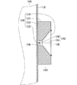
図2は、雰囲気保持治具およびワークを示す模式図であり、断面図である。
2 Atmosphere holding jig FIG. 2 is a schematic view showing an atmosphere holding jig and a workpiece, and is a cross-sectional view.
雰囲気保持治具1020の表面1200は、図2に示されるように、接触領域1220、非接触領域1221、開口1222および排気口1225を有する。雰囲気保持治具1020には、凹部1240および排気路1243が形成される。
As shown in FIG. 2, the
接触領域1220は、ワーク1040の外周面1120に接触する。非接触領域1221は、ワーク1040の表面1100に接触しない。
The
開口1222は、接触領域1220に囲まれる。接触領域1220がワーク1040の外周面1120に接触した場合は、ワーク1040の外周面1120で開口1222が閉塞される。凹部1240は開口1222に露出するが、開口1222がワーク1040の外周面1120で閉塞された場合は、開口1222を経由して凹部1240から窒素ガスが流出することが抑制され、開口1222を経由して凹部1240に大気が流入することが抑制される。
排気口1225は、非接触領域1221に囲まれる。これにより、ワーク1040と干渉せずに排気口1225から窒素ガスを排出できる。
The
排気路1243は、第1の区間1280および第2の区間1281を有する。第1の区間1280は、凹部1240寄りにあり、一定の径を有する。第1の区間1280が省略されてもよい。第2の区間1281は、排気口1225寄りにあり、排気口1225に近づくにつれて大きくなる径を有する。したがって、第2の区間1281は、排気口1225に近づくにつれて広がる。
The
供給機構1022が雰囲気保持治具1020に窒素ガスを供給した場合は、凹部1240を経由して排気口1225まで窒素ガスが流れる。凹部1240に流入した窒素ガスは、排気路1243を通って排気口1225から流出する。これにより、凹部1240から窒素ガス以外のガスが排除される。
When the
図2に示される排気のための構造によれば、窒素ガス以外のガスが凹部1240から効率的に排除される。しかし、排気のための構造が変更されてもよい。例えば、排気路1243以外の排気路が形成されてもよい。
According to the structure for exhaust shown in FIG. 2, gases other than nitrogen gas are efficiently excluded from the
開口1222は、排気口1225から見通される。このため、照射機構1021が排気口1225にレーザー光1140を入射させた場合は、排気口1225から排気路1243および凹部1240を順次に経由して開口1222を閉塞するワーク1040の外周面1120までレーザー光1140を伝搬させることができ、開口1222を閉塞するワーク1040の外周面1120にレーザー光1140を照射できる。
The opening 1222 is seen from the
3 照射機構
照射機構1021は、図1に示されるように、加工ヘッド1340および維持機構1341を備える。
3 Irradiation Mechanism The
加工ヘッド1340は、レーザー光1140を放射する。加工ヘッド1340が放射するレーザー光1140は、焦点を結ぶように収束させられる。
The
維持機構1341は、ワーク1040の外周面1120から加工ヘッド1340までの距離を一定に維持する。これにより、ワーク1040の外周面1120が完全な円周面でない場合でも、レーザー光1140がワーク1040の外周面1120において焦点を結ぶように照射機構1021が調整された後は、レーザー光1140がワーク1040の外周面1120において焦点を結ぶ状態が維持され、円板状の構造物1060がワーク1040における周方向の全体にわたって円筒状の構造物1061に均一にレーザー溶接される。
The
維持機構1341は、ステージ1360、ローラー1361、コイルばね1362、第1の台1363、第2の台1364およびエアシリンダー1365を備える。ステージ1360は、テーブル1380、ベース1381および車輪1382を備える。第1の台1363は、本体1400および車輪1401を備える。
The
加工ヘッド1340は、テーブル1380の上面に結合される。ローラー1361は、ベース1381に結合される。ローラー1361は、ステージ1360を介して加工ヘッド1340に結合される。これにより、加工ヘッド1340、ステージ1360およびローラー1361からなる結合体1410が形成され、加工ヘッド1340、ステージ1360およびローラー1361を一体的に動かすことができる。
ステージ1360においては、ベース1381の上面にテーブル1380が載せられ、ベース1381に対してテーブル1380が可動になっている。ベース1381に対してテーブル1380が動く方向は、ワーク1040における径方向のみに制限される。レーザー溶接装置1000においては、レーザー溶接に先立って、レーザー光1140がワーク1040の外周面1120において焦点を結ぶようにレーザー光1140の焦点位置が微調整される。焦点位置の微調整においては、ローラー1361をワーク1040の外周面1120に接触させた状態においてレーザー光1140がワーク1040の外周面1120において焦点を結ぶようにベース1381に対するテーブル1380の位置が微調整される。焦点位置の微調整が完了した後は、ベース1381に対してテーブル1380が固定される。
In the
ステージ1360は、焦点位置を微調整するために設けられる。このため、加工ヘッド1340において焦点位置を微調整できる場合等においては、ステージ1360が省略されローラー1361が加工ヘッド1340に直接的に結合されてもよいし、ローラー1361がステージ1360以外の構成物を介して加工ヘッド1340に結合されてもよい。
The
ローラー1361は、ワーク1040の外周面1120に接触し、ワーク1040の外周面1120の位置を検出する。
The
ローラー1361は、円板状の回転体1420を備える。回転体1420は、回転体1420の中心軸1430の周りに回転できるようにベース1381に結合される。回転体1420の中心軸1430は、ワーク1040の中心軸1080と平行をなす。維持機構1341がワーク1040の外周面1120から加工ヘッド1340までの距離を一定に維持する場合は、回転体1420の外周面1440がワーク1040の外周面1120に接触し、ワーク1040の回転に応じて回転体1420も回転する。回転体1420が回転することにより、ワーク1040の外周面1120に傷がつきにくくなる。円板状の回転体1420が球状の回転体に置き換えられてもよい。ワーク1040が硬い場合、ワーク1040の外周面1120が滑りやすい場合等においては、ローラー1361のような回転する接触子が回転しない接触子に置き換えられてもよい。
The
ローラー1361は、レーザー光1140の照射点1160から見てワーク1040における軸方向下側にある。ローラー1361がレーザー光1140の照射点1160から見てワーク1040における軸方向上側にあってもよい。
The
車輪1382は、ベース1381の下面に装着される。ステージ1360は、第1の台1363の上面に乗せられる。車輪1382は、ベース1381の下面と第1の台1363の上面との間にある。これにより、ステージ1360がワーク1040における径方向に第1の台1363に対して可動になり、結合体1410がワーク1040の外周面1120からの距離が変化する方向に可動になる。車輪1382が他の種類の可動化機構に置き換えられてもよい。例えば、車輪1382がリニアガイド等に置き換えられてもよい。
コイルばね1362の伸縮方向は、ワーク1040における径方向と一致する。コイルばね1362の一端は、ベース1381に結合される。コイルばね1362の一端がベース1381以外の結合体1410の構成物に結合されてもよい。例えば、コイルばね1362の一端がテーブル1380または加工ヘッド1340に結合されてもよい。コイルばね1362の他端は、第1の台1363に結合される。コイルばね1362は、ワーク1040における径方向内側にステージ1360を弾性的に押圧する。これにより、ワーク1040の外周面1120からの距離が短くなる方向に結合体1410が弾性的に押圧され、ローラー1361がワーク1040の外周面1120に接触する状態が維持される。コイルばね1362が他の種類の押圧機構に置き換えられてもよい。例えば、コイルばね1362が板ばね、ゴム片等に置き換えられてもよい。
The expansion / contraction direction of the
車輪1401は、本体1400の下面に装着される。第1の台1363は、第2の台1364の上面に乗せられる。車輪1401は、本体1400の下面と第2の台1364の上面との間にある。これにより、第1の台1363がワーク1040における径方向に第2の台1364に対して可動になり、第1の台1363および結合体1410がワーク1040における径方向に可動になる。
エアシリンダー1365は、第1の台1363をワーク1040における径方向に動かす。エアシリンダー1365は、レーザー溶接が行われる場合に第1の台1363を溶接位置まで前進させ、溶接が行われない場合に第1の台1363を退避位置まで後退させる。第1の台1363が溶接位置に配置された場合は、ローラー1361がワーク1040の外周面1120に接触する。第1の台1363が退避位置に配置された場合は、ローラー1361がワーク1040の外周面1120から離れる。エアシリンダー1365が他の種類の移動機構に置き換えられてもよい。例えば、エアシリンダー1365が電磁アクチュエーターに置き換えられてもよい。
The
4 レーザー溶接装置の転用
レーザー溶接装置1000は、円筒容器状の接合体以外の接合体の生産にも転用される。一般的に言えば、レーザー溶接装置1000は、一の構造物が他の構造物にレーザー溶接された接合体の生産に転用される。レーザー溶接装置1000が転用される場合は、ワークの表面の形状に適合する接触領域を有する雰囲気保持治具が準備される。溶接線の形状が環状でない場合は、回転機構1023が、回転以外の動きをワークにさせる機構に置き換えられる。
4. Diversion of laser welding apparatus The
上記の発明の詳細な説明は、全部の局面において例示であって本発明を限定しない。したがって、本発明の範囲からはずれることなく無数の修正および変形が案出されうる。 The above detailed description of the invention is illustrative in all aspects and does not limit the invention. Thus, numerous modifications and variations can be devised without departing from the scope of the present invention.
1000 レーザー溶接装置
1020 雰囲気保持治具
1021 照射機構
1022 供給機構
1023 回転機構
1040 ワーク
1340 加工ヘッド
1341 維持機構
1361 ローラー
1362 コイルばね
1000
レーザー溶接装置は、加工ヘッド、維持機構、走査機構、雰囲気保持治具および供給機構を備える。加工ヘッドは、レーザー光を放射する。維持機構は、ワークの表面から加工ヘッドまでの距離を一定に維持する。走査機構は、レーザー光の照射点にワークの表面を走査させる。雰囲気保持治具は、表面を有する。表面は、接触領域、非接触領域、開口および排気口を有する。接触領域は、ワークの表面に接触する。非接触領域は、ワークの表面に接触しない。開口は、接触領域に囲まれ、接触領域がワークの表面に接触した場合にワークの表面で閉塞される。排気口は、非接触領域に囲まれる。雰囲気保持治具には、凹部が形成される。凹部は、開口に露出し、排気口に通じる。排気口からは開口が見通される。供給機構は、雰囲気保持治具にシールドガスを供給し、凹部を経由して排気口までシールドガスを流す。
加工ヘッドは、排気口にレーザー光を入射させ、排気口から凹部を経由して開口までレーザー光を伝搬させ、開口を閉塞するワークの表面にレーザー光を照射する。
維持機構は、接触子、可動化機構および押圧機構を備える。接触子は、ワークの表面に接触し加工ヘッドに結合され加工ヘッドと結合体を構成する。可動化機構は、ワークの表面からの距離が変化する方向に結合体を可動にする。押圧機構は、ワークの表面からの距離が短くなる方向に結合体を弾性的に押圧する。
The laser welding apparatus includes a processing head, a maintenance mechanism, a scanning mechanism, an atmosphere holding jig, and a supply mechanism . The processing head emits laser light. The maintenance mechanism maintains a constant distance from the workpiece surface to the machining head. The scanning mechanism scans the surface of the workpiece at the irradiation point of the laser beam. The atmosphere holding jig has a surface. The surface has a contact area, a non-contact area, an opening and an exhaust port. The contact area contacts the surface of the workpiece. The non-contact area does not contact the surface of the workpiece. The opening is surrounded by the contact area, and is closed by the surface of the workpiece when the contact area contacts the surface of the workpiece. The exhaust port is surrounded by a non-contact area. A concave portion is formed in the atmosphere holding jig. The recess is exposed to the opening and communicates with the exhaust port. An opening can be seen from the exhaust port. The supply mechanism supplies the shielding gas to the atmosphere holding jig and causes the shielding gas to flow to the exhaust port via the recess.
The processing head causes the laser beam to enter the exhaust port, propagates the laser beam from the exhaust port to the opening through the recess, and irradiates the surface of the workpiece that closes the opening with the laser beam.
The maintenance mechanism includes a contact, a mobilization mechanism, and a pressing mechanism. The contact is brought into contact with the surface of the workpiece and coupled to the machining head to form a coupled body with the machining head. The mobilization mechanism moves the coupled body in a direction in which the distance from the surface of the workpiece changes. The pressing mechanism elastically presses the combined body in a direction in which the distance from the surface of the workpiece becomes shorter.
Claims (6)
ワークの表面から前記加工ヘッドまでの距離を一定に維持する維持機構と、
レーザー光の照射点にワークの表面を走査させる走査機構と、
を備える
レーザー溶接装置。 A processing head that emits laser light;
A maintenance mechanism that maintains a constant distance from the surface of the workpiece to the processing head;
A scanning mechanism that scans the surface of the workpiece at the irradiation point of the laser beam;
A laser welding apparatus comprising:
ワークの表面に接触し前記加工ヘッドに結合され前記加工ヘッドと結合体を構成する接触子と、
ワークの表面からの距離が変化する方向に前記結合体を可動にする可動化機構と、
ワークの表面からの距離が短くなる方向に前記結合体を弾性的に押圧する押圧機構と、
を備える
請求項1のレーザー溶接装置。 The maintenance mechanism is
A contact that contacts the surface of the workpiece and is coupled to the processing head to form a combined body with the processing head;
A mobilization mechanism for moving the combined body in a direction in which the distance from the surface of the workpiece changes;
A pressing mechanism that elastically presses the combined body in a direction in which the distance from the surface of the workpiece becomes shorter;
The laser welding apparatus according to claim 1, comprising:
前記雰囲気保持治具にシールドガスを供給し、前記凹部を経由して前記排気口までシールドガスを流す供給機構と、
をさらに備え、
前記加工ヘッドは、前記排気口にレーザー光を入射させ、前記排気口から前記凹部を経由して前記開口までレーザー光を伝搬させ、前記開口を閉塞するワークの表面にレーザー光を照射する
を備える請求項1または2のレーザー溶接装置。 Having a surface, the surface has a contact area, a non-contact area, an opening and an exhaust port, the contact area is in contact with the surface of the workpiece, the non-contact area is not in contact with the surface of the workpiece, and the opening is Surrounded by the contact area, when the contact area contacts the surface of the workpiece, the opening is closed at the surface of the workpiece, the exhaust port is surrounded by the non-contact area, a recess is formed, the recess is the An atmosphere holding jig that is exposed to an opening, the recess communicates with the exhaust port, and the opening is seen through the exhaust port;
A supply mechanism for supplying a shielding gas to the atmosphere holding jig and flowing the shielding gas to the exhaust port via the recess;
Further comprising
The processing head includes a laser beam incident on the exhaust port, the laser beam propagating from the exhaust port to the opening via the concave portion, and irradiating the surface of the workpiece closing the opening with the laser beam. The laser welding apparatus according to claim 1 or 2.
前記排気路は、前記凹部から前記排気口へ至り、前記排気口に近づくにつれて広がる区間を有する
請求項3のレーザー溶接装置。 An exhaust path is formed in the atmosphere holding jig,
4. The laser welding apparatus according to claim 3, wherein the exhaust path has a section that extends from the recess to the exhaust port and expands toward the exhaust port. 5.
前記走査機構が、前記雰囲気保持治具およびレーザー光の照射点をワークにおける周方向にワークの外周面に対して相対移動させる回転機構であり、
前記接触領域がワークの外周面に接触する
請求項3または4のレーザー溶接装置。 The surface of the work has an outer peripheral surface that is a circumferential surface,
The scanning mechanism is a rotating mechanism that moves the atmosphere holding jig and the laser beam irradiation point relative to the outer peripheral surface of the work in the circumferential direction of the work,
The laser welding apparatus according to claim 3 or 4, wherein the contact area is in contact with the outer peripheral surface of the workpiece.
(b) 前記レーザー溶接装置を用いて前記第1の構造物を前記第2の構造物にレーザー溶接し接合体を作製する工程と、
を備える接合体を生産する方法。 (a) preparing the first structure, the second structure, and the laser welding apparatus according to any one of claims 1 to 5;
(b) laser welding the first structure to the second structure using the laser welding apparatus to produce a joined body;
Of producing a joined body comprising:
Priority Applications (1)
| Application Number | Priority Date | Filing Date | Title |
|---|---|---|---|
| JP2015119046A JP6046771B1 (en) | 2015-06-12 | 2015-06-12 | Laser welding apparatus and method for producing joined body |
Applications Claiming Priority (1)
| Application Number | Priority Date | Filing Date | Title |
|---|---|---|---|
| JP2015119046A JP6046771B1 (en) | 2015-06-12 | 2015-06-12 | Laser welding apparatus and method for producing joined body |
Publications (2)
| Publication Number | Publication Date |
|---|---|
| JP6046771B1 JP6046771B1 (en) | 2016-12-21 |
| JP2017001068A true JP2017001068A (en) | 2017-01-05 |
Family
ID=57572406
Family Applications (1)
| Application Number | Title | Priority Date | Filing Date |
|---|---|---|---|
| JP2015119046A Active JP6046771B1 (en) | 2015-06-12 | 2015-06-12 | Laser welding apparatus and method for producing joined body |
Country Status (1)
| Country | Link |
|---|---|
| JP (1) | JP6046771B1 (en) |
Cited By (1)
| Publication number | Priority date | Publication date | Assignee | Title |
|---|---|---|---|---|
| WO2018179632A1 (en) | 2017-03-31 | 2018-10-04 | 日本精工株式会社 | Laser welding device, laser processing device, laser welding method, bearing manufacturing method, machine manufacturing method, vehicle manufacturing method, bearing, machine, and vehicle |
Citations (7)
| Publication number | Priority date | Publication date | Assignee | Title |
|---|---|---|---|---|
| JPH07136965A (en) * | 1993-11-19 | 1995-05-30 | Pfu Ltd | Object handling equipment |
| JP2002103078A (en) * | 2000-09-29 | 2002-04-09 | Ishikawajima Harima Heavy Ind Co Ltd | Laser welding method and apparatus |
| JP2004276038A (en) * | 2003-03-13 | 2004-10-07 | Horie Metal Co Ltd | Laser welding method and apparatus |
| JP2008114252A (en) * | 2006-11-02 | 2008-05-22 | Sony Corp | Laser processing apparatus, laser processing head, and laser processing method |
| JP2008212996A (en) * | 2007-03-06 | 2008-09-18 | Toyota Motor Corp | Laser welding method, work piece, and laser welding apparatus |
| JP2014012288A (en) * | 2012-07-04 | 2014-01-23 | Mitsubishi Heavy Ind Ltd | Laser welding apparatus, and welding method thereof |
| JP2014133668A (en) * | 2013-01-08 | 2014-07-24 | Toshiba Corp | Joining method and joining device |
-
2015
- 2015-06-12 JP JP2015119046A patent/JP6046771B1/en active Active
Patent Citations (7)
| Publication number | Priority date | Publication date | Assignee | Title |
|---|---|---|---|---|
| JPH07136965A (en) * | 1993-11-19 | 1995-05-30 | Pfu Ltd | Object handling equipment |
| JP2002103078A (en) * | 2000-09-29 | 2002-04-09 | Ishikawajima Harima Heavy Ind Co Ltd | Laser welding method and apparatus |
| JP2004276038A (en) * | 2003-03-13 | 2004-10-07 | Horie Metal Co Ltd | Laser welding method and apparatus |
| JP2008114252A (en) * | 2006-11-02 | 2008-05-22 | Sony Corp | Laser processing apparatus, laser processing head, and laser processing method |
| JP2008212996A (en) * | 2007-03-06 | 2008-09-18 | Toyota Motor Corp | Laser welding method, work piece, and laser welding apparatus |
| JP2014012288A (en) * | 2012-07-04 | 2014-01-23 | Mitsubishi Heavy Ind Ltd | Laser welding apparatus, and welding method thereof |
| JP2014133668A (en) * | 2013-01-08 | 2014-07-24 | Toshiba Corp | Joining method and joining device |
Cited By (3)
| Publication number | Priority date | Publication date | Assignee | Title |
|---|---|---|---|---|
| WO2018179632A1 (en) | 2017-03-31 | 2018-10-04 | 日本精工株式会社 | Laser welding device, laser processing device, laser welding method, bearing manufacturing method, machine manufacturing method, vehicle manufacturing method, bearing, machine, and vehicle |
| US11213916B2 (en) | 2017-03-31 | 2022-01-04 | Nsk Ltd. | Laser machining method |
| US11794279B2 (en) | 2017-03-31 | 2023-10-24 | Nsk Ltd. | Laser machining method |
Also Published As
| Publication number | Publication date |
|---|---|
| JP6046771B1 (en) | 2016-12-21 |
Similar Documents
| Publication | Publication Date | Title |
|---|---|---|
| US11135772B2 (en) | Additive-manufacturing head and manufacturing machine | |
| CN107584205B (en) | Method for laser machining of metallic materials, and associated machine and computer program | |
| JP6749308B2 (en) | LASER LAMINATION MODELING APPARATUS AND LASER LAMINATION METHOD | |
| US20160151862A1 (en) | Device for laser processing of a surface of a workpiece or for post-treatment of a coating on the outside or the inside of a workpiece | |
| EP3012060A1 (en) | Powder cladding nozzle | |
| US20190232564A1 (en) | Apparatus for additively manufacturing three-dimensional objects | |
| WO2014123080A1 (en) | Laser processing apparatus and laser processing method | |
| US20160207144A1 (en) | Laser processing apparatus | |
| KR20150118312A (en) | system and method for cutting using laser | |
| CN113441835A (en) | Welding equipment and application and welding method thereof | |
| JP2005334951A (en) | Laser hardening tool | |
| US8044323B2 (en) | Apparatus for improving residual stress of piping technical field | |
| JP6046771B1 (en) | Laser welding apparatus and method for producing joined body | |
| KR101401486B1 (en) | Method for processing material with laser | |
| US8420976B2 (en) | Laser welder | |
| CN104294011B (en) | Hole laser quenching head and process for quenching | |
| US20180345404A1 (en) | Laser processing device, laser processing method, optical system, and cladded article | |
| KR102288791B1 (en) | Laser processing head and laser processing device and adjustment method of laser processing head | |
| CN102019504B (en) | Laser adaption honing system and method | |
| CN108025397B (en) | Valve needle for fluid injection valve, fluid injection valve and method for making valve needle | |
| KR20220045806A (en) | LASER machining apparatus | |
| JPS6246166Y2 (en) | ||
| JP7561676B2 (en) | Laser processing device, welding method, water heater manufacturing method, compressor manufacturing method, and laser processing method | |
| JP6713313B2 (en) | Processing head for laser processing equipment | |
| US20220212285A1 (en) | Welding method and welded member |
Legal Events
| Date | Code | Title | Description |
|---|---|---|---|
| TRDD | Decision of grant or rejection written | ||
| A01 | Written decision to grant a patent or to grant a registration (utility model) |
Free format text: JAPANESE INTERMEDIATE CODE: A01 Effective date: 20161101 |
|
| A61 | First payment of annual fees (during grant procedure) |
Free format text: JAPANESE INTERMEDIATE CODE: A61 Effective date: 20161117 |
|
| R150 | Certificate of patent or registration of utility model |
Ref document number: 6046771 Country of ref document: JP Free format text: JAPANESE INTERMEDIATE CODE: R150 |