JP2017002965A - Switching valve and refrigeration cycle system - Google Patents
Switching valve and refrigeration cycle system Download PDFInfo
- Publication number
- JP2017002965A JP2017002965A JP2015116043A JP2015116043A JP2017002965A JP 2017002965 A JP2017002965 A JP 2017002965A JP 2015116043 A JP2015116043 A JP 2015116043A JP 2015116043 A JP2015116043 A JP 2015116043A JP 2017002965 A JP2017002965 A JP 2017002965A
- Authority
- JP
- Japan
- Prior art keywords
- joint
- valve
- valve housing
- compressor
- switching valve
- Prior art date
- Legal status (The legal status is an assumption and is not a legal conclusion. Google has not performed a legal analysis and makes no representation as to the accuracy of the status listed.)
- Granted
Links
- 238000005057 refrigeration Methods 0.000 title description 14
- 239000003507 refrigerant Substances 0.000 claims description 42
- 239000012530 fluid Substances 0.000 claims description 8
- 239000002826 coolant Substances 0.000 claims description 3
- 238000001816 cooling Methods 0.000 description 10
- 238000010438 heat treatment Methods 0.000 description 9
- 230000000694 effects Effects 0.000 description 4
- 238000005219 brazing Methods 0.000 description 3
- 238000003466 welding Methods 0.000 description 3
- 238000005452 bending Methods 0.000 description 2
- 238000010586 diagram Methods 0.000 description 2
- 238000000034 method Methods 0.000 description 2
- 230000006866 deterioration Effects 0.000 description 1
- 238000005304 joining Methods 0.000 description 1
- 239000002184 metal Substances 0.000 description 1
- 238000012856 packing Methods 0.000 description 1
- 230000002093 peripheral effect Effects 0.000 description 1
- 238000003825 pressing Methods 0.000 description 1
- 238000004904 shortening Methods 0.000 description 1
Images



Classifications
-
- F—MECHANICAL ENGINEERING; LIGHTING; HEATING; WEAPONS; BLASTING
- F25—REFRIGERATION OR COOLING; COMBINED HEATING AND REFRIGERATION SYSTEMS; HEAT PUMP SYSTEMS; MANUFACTURE OR STORAGE OF ICE; LIQUEFACTION SOLIDIFICATION OF GASES
- F25B—REFRIGERATION MACHINES, PLANTS OR SYSTEMS; COMBINED HEATING AND REFRIGERATION SYSTEMS; HEAT PUMP SYSTEMS
- F25B41/00—Fluid-circulation arrangements
- F25B41/20—Disposition of valves, e.g. of on-off valves or flow control valves
-
- F—MECHANICAL ENGINEERING; LIGHTING; HEATING; WEAPONS; BLASTING
- F25—REFRIGERATION OR COOLING; COMBINED HEATING AND REFRIGERATION SYSTEMS; HEAT PUMP SYSTEMS; MANUFACTURE OR STORAGE OF ICE; LIQUEFACTION SOLIDIFICATION OF GASES
- F25B—REFRIGERATION MACHINES, PLANTS OR SYSTEMS; COMBINED HEATING AND REFRIGERATION SYSTEMS; HEAT PUMP SYSTEMS
- F25B41/00—Fluid-circulation arrangements
- F25B41/20—Disposition of valves, e.g. of on-off valves or flow control valves
- F25B41/22—Disposition of valves, e.g. of on-off valves or flow control valves between evaporator and compressor
-
- F—MECHANICAL ENGINEERING; LIGHTING; HEATING; WEAPONS; BLASTING
- F25—REFRIGERATION OR COOLING; COMBINED HEATING AND REFRIGERATION SYSTEMS; HEAT PUMP SYSTEMS; MANUFACTURE OR STORAGE OF ICE; LIQUEFACTION SOLIDIFICATION OF GASES
- F25B—REFRIGERATION MACHINES, PLANTS OR SYSTEMS; COMBINED HEATING AND REFRIGERATION SYSTEMS; HEAT PUMP SYSTEMS
- F25B41/00—Fluid-circulation arrangements
- F25B41/30—Expansion means; Dispositions thereof
-
- F—MECHANICAL ENGINEERING; LIGHTING; HEATING; WEAPONS; BLASTING
- F25—REFRIGERATION OR COOLING; COMBINED HEATING AND REFRIGERATION SYSTEMS; HEAT PUMP SYSTEMS; MANUFACTURE OR STORAGE OF ICE; LIQUEFACTION SOLIDIFICATION OF GASES
- F25B—REFRIGERATION MACHINES, PLANTS OR SYSTEMS; COMBINED HEATING AND REFRIGERATION SYSTEMS; HEAT PUMP SYSTEMS
- F25B41/00—Fluid-circulation arrangements
- F25B41/30—Expansion means; Dispositions thereof
- F25B41/31—Expansion valves
-
- F—MECHANICAL ENGINEERING; LIGHTING; HEATING; WEAPONS; BLASTING
- F25—REFRIGERATION OR COOLING; COMBINED HEATING AND REFRIGERATION SYSTEMS; HEAT PUMP SYSTEMS; MANUFACTURE OR STORAGE OF ICE; LIQUEFACTION SOLIDIFICATION OF GASES
- F25B—REFRIGERATION MACHINES, PLANTS OR SYSTEMS; COMBINED HEATING AND REFRIGERATION SYSTEMS; HEAT PUMP SYSTEMS
- F25B2313/00—Compression machines, plants or systems with reversible cycle not otherwise provided for
- F25B2313/027—Compression machines, plants or systems with reversible cycle not otherwise provided for characterised by the reversing means
Landscapes
- Engineering & Computer Science (AREA)
- Physics & Mathematics (AREA)
- Mechanical Engineering (AREA)
- Thermal Sciences (AREA)
- General Engineering & Computer Science (AREA)
- Multiple-Way Valves (AREA)
- Valve Housings (AREA)
Abstract
【課題】圧縮機から弁ハウジングまでに到るD継手の長さを短くして、切換弁を小型化できるとともに、切換弁における熱ロスを低減できる切換弁を提供する。
【解決手段】弁ハウジング1に対して、D継手11、S継手12、E継手13及びC継手14を、それぞれ導通する。S継手12に対してE継手13またはC継手14の一方を弁ハウジング1内のスライド弁にて択一的に切換導通する。C継手14またはE継手13のうちの他の方を弁ハウジング1内を介してD継手11に導通する。S継手12、E継手13、C継手14及びD継手11を、その直管部分を同方向に向けて併設する。D継手11の弁ハウジング1側の接続端部11aを、S継手12、E継手13及びC継手14と併設される直管部分に対して略直角となる方向に屈曲させる。接続端部11aを弁ハウジング1に接続させる。
【選択図】図1Disclosed is a switching valve in which the length of a D joint extending from a compressor to a valve housing is shortened so that the switching valve can be reduced in size and heat loss in the switching valve can be reduced.
A D joint 11, an S joint 12, an E joint 13, and a C joint 14 are electrically connected to a valve housing 1, respectively. One of the E joint 13 and the C joint 14 is selectively switched to the S joint 12 by a slide valve in the valve housing 1. The other of the C joint 14 and the E joint 13 is conducted to the D joint 11 through the valve housing 1. The S joint 12, the E joint 13, the C joint 14, and the D joint 11 are provided side by side with their straight pipe portions directed in the same direction. The connection end 11a on the valve housing 1 side of the D joint 11 is bent in a direction substantially perpendicular to the straight pipe portion provided side by side with the S joint 12, the E joint 13, and the C joint 14. The connection end 11a is connected to the valve housing 1.
[Selection] Figure 1
Description
本発明は、ヒートポンプ式の冷凍サイクルの圧縮機等に接続され、冷媒の流路を切り換える切換弁及び冷凍サイクルシステムに関する。 The present invention relates to a switching valve and a refrigeration cycle system that are connected to a compressor or the like of a heat pump type refrigeration cycle and switch a refrigerant flow path.
従来、切換弁として、例えば図6に示すものがある。この切換弁は、圧縮機の吐出側に接続されるD継手91、圧縮機の吸入側に接続されるS継手92、室内熱交換器に接続されるE継手93、室外熱交換器に接続されるC継手94を備えており、これらの継手は弁ハウジング95に接続されている。また、弁ハウジング95内にはスライド弁が配設されており、このスライド弁を移動することにより、S継手92をE継手93またはC継手94の一方に択一的に切換導通するとともに、S継手92に対して非導通となるC継手94またはE継手93を弁ハウジング95内を介してD継手91に導通する。また、スライド弁を切換作動させるパイロット弁96を備えている。
Conventionally, for example, there is a switching valve shown in FIG. This switching valve is connected to a
そして、この従来の切換弁は、スライド弁によって切換を行うためにE継手93とC継手94はS継手92の両側に配置されてスライド弁の移動方向(弁ハウジング95の軸方向)に併設されている。また、D継手91はS継手92と共に圧縮機に接続されるため、D継手91はS継手92の引き出し方向に合わせてU字状に曲げ加工されている。なお、このようなスライド弁を用いた切換弁として、例えば実開昭62−126807号公報(特許文献1)に開示されたものがある。
In this conventional switching valve, the
従来の切換弁では、D継手91が、弁ハウジング95から一旦S継手92とは反対側に延びて、さらにU字状に曲げ加工され、S継手92と平行になるように引き出されている。このため、S継手92の反対側にD継手91の曲げ加工部分を配置するためのスペースを必要とし、切換弁全体のサイズが大きくなるという問題があった。また、D継手91には圧縮機から吐出される高温冷媒が流れるが、曲げ加工部分に伴ってD継手91全体の長さが長くなってしまう分、このD継手91から大気に放出する熱量により切換弁における熱ロスが大きくなり、システムの運転効率の低下に繋がっていた。
In the conventional switching valve, the
これに対して、特許文献1のように、全ての継手を弁ハウジングに対して同じ側で直線的に並べる構造にすれば、D継手は短くでき図6のような一般的な切換弁に比べてサイズを小さくはできる。しかし、この特許文献1のような構造では、全ての継手が弁ハウジングに沿って直線的に並んでいるため、外力がかかる方向によっては、その外力に対して弱い構造となっている。例えば、各継手を含む面に対して交差する方向の力に対して弱い構造となっている。 On the other hand, if it is made into the structure which arranges all the joints linearly on the same side with respect to a valve housing like patent document 1, D joint can be shortened compared with the general switching valve like FIG. The size can be reduced. However, in the structure as in Patent Document 1, since all the joints are linearly arranged along the valve housing, the structure is weak against the external force depending on the direction in which the external force is applied. For example, it has a structure that is weak against the force in the direction intersecting the plane including each joint.
本発明は、圧縮機から弁ハウジングまでに到るD継手の長さを短くすることで切換弁を小型化できるとともに、切換弁における熱ロスを低減でき、かつ、外力に対して強い切換弁を提供することを課題とする。 The present invention can reduce the size of the switching valve by shortening the length of the D joint from the compressor to the valve housing, reduce the heat loss in the switching valve, and provide a switching valve that is strong against external force. The issue is to provide.
請求項1の切換弁は、密閉された弁ハウジングに対して、圧縮機の吐出側に接続されるD継手と、該圧縮機の吸入側に接続されるS継手と、一方の熱交換器に接続されるE継手と、他方の熱交換器に接続されるC継手と、がそれぞれ導通され、前記S継手に対してE継手またはC継手を前記弁ハウジング内に配設されたスライド弁にて択一的に切換導通するとともに、S継手に対して非導通となるC継手またはE継手を前記弁ハウジング内を介して前記D継手に導通するようにした切換弁において、前記S継手と、前記E継手と、前記C継手と、前記D継手とを、その直管部分を同方向に向けて併設するとともに、前記D継手の前記弁ハウジング側の接続端部を、当該D継手の前記S継手、E継手及びC継手と併設される前記直管部分に対して略直角となる方向に屈曲させて、該接続端部を該弁ハウジングに接続したことを特徴とする。 According to a first aspect of the present invention, there is provided a switching valve having a D joint connected to a discharge side of a compressor, an S joint connected to a suction side of the compressor, and one heat exchanger with respect to a sealed valve housing. The E joint to be connected and the C joint to be connected to the other heat exchanger are respectively conducted, and the E joint or the C joint is connected to the S joint by a slide valve disposed in the valve housing. In the switching valve that is selectively switched conductive and non-conductive to the S joint, the C joint or E joint is electrically connected to the D joint through the valve housing. The E joint, the C joint, and the D joint are provided side by side with their straight pipe portions facing in the same direction, and the connection end of the D joint on the valve housing side is connected to the S joint of the D joint. , For the straight pipe part that is installed together with E joint and C joint It is bent in the direction substantially perpendicular, characterized in that connected to the connecting end to the valve housing.
請求項2の切換弁は、請求項1に記載の切換弁であって、前記S継手に接続されるSポートと、前記E継手と前記C継手にそれぞれ接続される2つの切換ポートとが形成された弁座部材が、前記弁ハウジング内に配設されるとともに、該弁座部材の前記スライド弁に対向する弁座面が、前記D継手の前記接続端部の軸に対して、直交するように配置され、前記S継手、E継手及びC継手の前記弁ハウジング側の接続端部を、当該S継手、E継手及びC継手の前記D継手と平行な前記直管部分に対して、略直角となる方向に屈曲させて、前記Sポート及び2つの切換ポートにそれぞれ接続したことを特徴とする。 The switching valve according to claim 2 is the switching valve according to claim 1, and includes an S port connected to the S joint and two switching ports respectively connected to the E joint and the C joint. The valve seat member is disposed in the valve housing, and the valve seat surface of the valve seat member facing the slide valve is orthogonal to the axis of the connection end of the D joint. The connection ends on the valve housing side of the S joint, E joint, and C joint are substantially parallel to the straight pipe portion parallel to the D joint of the S joint, E joint, and C joint. It is characterized in that it is bent in a direction perpendicular to each other and connected to the S port and two switching ports.
請求項3の切換弁は、請求項2に記載の切換弁であって、前記D継手の前記接続端部と、前記E継手または前記C継手のいずれか一方の前記接続端部とを、同軸にして前記弁座部材を挟んで対向配置したことを特徴とする。 The switching valve according to claim 3 is the switching valve according to claim 2, wherein the connection end portion of the D joint and the connection end portion of either the E joint or the C joint are coaxially connected. The valve seat members are arranged opposite to each other.
請求項4の切換弁は、請求項1乃至3のいずれか一項に記載の切換弁であって、前記D継手の高圧流体及び前記S継手の低圧流体の圧力差を利用して前記スライド弁を切換作動させるパイロット弁を備え、前記パイロット弁を、前記弁ハウジングの軸方向において前記D継手の前記接続端部と併設して配置されていることを特徴とする。 A switching valve according to a fourth aspect is the switching valve according to any one of the first to third aspects, wherein the slide valve utilizes a pressure difference between the high pressure fluid of the D joint and the low pressure fluid of the S joint. And a pilot valve that is arranged side by side with the connection end of the D joint in the axial direction of the valve housing.
請求項5の冷凍サイクルシステムは、流体である冷媒を圧縮する圧縮機と、前記一方の熱交換器と前記他方の熱交換器との間にて冷媒を膨張させて減圧する膨張手段と、請求項1乃至4のいずれか一項に記載の切換弁と、を備え、前記切換弁は、前記圧縮機で圧縮した冷媒を前記D継手から前記弁ハウジングの内部に流入させるとともに、前記C継手を介して前記他方の熱交換器へ冷媒を流出させ、前記一方の熱交換器から前記E継手に流入した冷媒を前記S継手から前記圧縮機に還流させるか、又は、前記圧縮機で圧縮した冷媒を前記D継手から前記弁ハウジングの内部に流入させるとともに、前記E継手を介して前記一方の熱交換器へ冷媒を流出させ、前記他方の熱交換器から前記C継手に流入した冷媒を前記S継手から前記圧縮機に還流させることを特徴とする。 A refrigeration cycle system according to a fifth aspect includes a compressor that compresses a refrigerant that is a fluid, an expansion unit that expands and depressurizes the refrigerant between the one heat exchanger and the other heat exchanger, and The switching valve according to any one of Items 1 to 4, wherein the switching valve allows the refrigerant compressed by the compressor to flow into the valve housing from the D joint, and to connect the C joint. Through which the refrigerant flows out to the other heat exchanger, and the refrigerant that has flowed into the E joint from the one heat exchanger is returned to the compressor from the S joint, or is compressed by the compressor From the D joint to the inside of the valve housing, the refrigerant flows out to the one heat exchanger via the E joint, and the refrigerant that has flowed into the C joint from the other heat exchanger flows into the S joint. Return from the joint to the compressor Characterized in that to.
請求項1の切換弁によれば、D継手の弁ハウジング側の接続端部が、他の継手と併設される直管部分に対して略直角となる方向に屈曲され、この接続端部が弁ハウジングに接続されているので、D継手が弁ハウジングのS継手とは反対側に突出することがなく、D継手の長手方向の長さが短くなり切換弁を小型化できるとともに、切換弁における熱ロスが低減され、外力に対して強いものとなる。 According to the switching valve of the first aspect, the connection end on the valve housing side of the D joint is bent in a direction substantially perpendicular to the straight pipe portion provided together with the other joint, and this connection end is the valve. Since it is connected to the housing, the D joint does not protrude to the side opposite to the S joint of the valve housing, the length in the longitudinal direction of the D joint is shortened, and the switching valve can be reduced in size. Loss is reduced and it is strong against external force.
請求項2の切換弁によれば、請求項1の効果に加えて、弁座部材の弁座面がD継手の接続端部の軸に対して直交するように配置され、S継手、E継手及びC継手の弁ハウジング側の接続端部がD継手と平行な直管部分に対して略直角となる方向に屈曲され、この接続端部が弁座部材の各ポートにそれぞれ接続されているので、D継手から弁座部材のポートに向かう冷媒の流れに乱流が生じにくくなり、冷媒がスムーズに流れ、システムの運転効率の低下を抑制できる。 According to the switching valve of claim 2, in addition to the effect of claim 1, the valve seat surface of the valve seat member is disposed so as to be orthogonal to the axis of the connection end of the D joint, and the S joint and the E joint And the connection end on the valve housing side of the C joint is bent in a direction substantially perpendicular to the straight pipe portion parallel to the D joint, and this connection end is connected to each port of the valve seat member. The turbulent flow is unlikely to occur in the flow of the refrigerant from the D joint toward the port of the valve seat member, the refrigerant flows smoothly, and a reduction in the operating efficiency of the system can be suppressed.
請求項3の切換弁によれば、請求項2の効果に加えて、暖房運転時または冷房運転時のシステムの運転効率の低下をさらに抑制できる。 According to the switching valve of the third aspect, in addition to the effect of the second aspect, it is possible to further suppress a decrease in the operating efficiency of the system during the heating operation or the cooling operation.
請求項4の切換弁によれば、請求項1乃至3の効果に加えて、D継手の横をパイロット弁の配置場所として有効利用でき切換弁を小型化できる。 According to the switching valve of the fourth aspect, in addition to the effects of the first to third aspects, the side of the D joint can be effectively used as the location of the pilot valve, and the switching valve can be downsized.
請求項5の冷凍サイクルシステムによれば、請求項1乃至4と同様な効果が得られる。 According to the refrigeration cycle system of claim 5, the same effects as in claims 1 to 4 can be obtained.
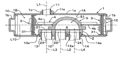
次に、本発明の切換弁の実施形態を図面を参照して説明する。図1は第1実施形態の切換弁の左側面図(図1(A) )及び正面図(図1(B))、図2は図1(B)のA−A断面図、図3は図1(B)のB−B断面図である。 Next, an embodiment of the switching valve of the present invention will be described with reference to the drawings. 1 is a left side view (FIG. 1 (A)) and a front view (FIG. 1 (B)) of the switching valve of the first embodiment, FIG. 2 is a cross-sectional view taken along line AA in FIG. 1 (B), and FIG. It is BB sectional drawing of FIG.1 (B).
この実施形態に係る切換弁10は四方切換弁であり、パイロット弁20により切り換えられる。図2及び図3に示すように、切換弁10は、弁ハウジング1内に、弁座部材2、一対のピストン3,3、連結板4、スライド弁5を備えている。
The
弁ハウジング1は円筒形状の円筒部1aと2つのキャップ部1b,1bとで構成されている。キャップ部1b,1bはそれぞれ円筒部1aの端部を塞ぐように円筒部1aに対してかしめられ、その後ろう付けや溶接等の接合手段が施されており、これにより弁ハウジング1は密閉されている。なお、円筒部1a及びキャップ部1b,1bの中心線が弁ハウジング1の軸線L10となっている。弁ハウジング1の側部の一箇所にはバーリング加工により接続筒1cが形成されており、この接続筒1cには弁ハウジング1内に開口する接続端部11aを嵌合させてD継手11が取り付けられている。このD継手11は接続端部11aの部分にて溶接やろう付け等により弁ハウジング1に固着されている。これにより、D継手11は弁ハウジング1内に導通されている。
The valve housing 1 includes a cylindrical
弁座部材2は、弁座面21を弁ハウジング1の軸線L10と平行にして弁ハウジング1内の中間部に配設されている。この弁座部材2には、弁ハウジング1の軸線L10方向に一直線上に並んでSポート22,Eポート23、及びCポート24が形成されている。そして、弁座部材2及び弁ハウジング1には、Sポート22、Eポート23、Cポート24にそれぞれ対応するS継手12、E継手13、C継手14が取り付けられている。S継手12、E継手13及びC継手14は、接続端部12a,13a,14aを円筒部1aの壁を貫通させて弁座部材2に嵌合され、この接続端部12a,13a,14aの部分にて、S継手12、E継手13及びC継手14は溶接やろう付け等により弁ハウジング1及び弁座部材2に固着されている。これにより、S継手12、E継手13、C継手14が弁ハウジング1内に導通されている。
The valve seat member 2 is disposed at an intermediate portion in the valve housing 1 with the
図3に示すように、一対のピストン3,3は互いに対向配置され、この一対のピストン3,3はパッキン31,31を円筒部1aの内周面に押圧しながら往復移動可能となっている。これにより、弁ハウジング1の内部は、2つのピストン3,3により、中央部の主弁室1Aと主弁室1Aの両側の2つの副弁室1B,1Cとに仕切られている。
As shown in FIG. 3, the pair of pistons 3 and 3 are arranged to face each other, and the pair of pistons 3 and 3 can reciprocate while pressing the packings 31 and 31 against the inner peripheral surface of the
連結板4は金属板からなり、この連結板4は、弁ハウジング1の軸線L10上に配置されるようにピストン3,3の間に架設されている。また、連結板4は、その中央にスライド弁5を保持しており、このスライド弁5の両側に透孔4a,4bが形成されている。そして、スライド弁5は、ピストン3,3が移動すると連結板4に連動して弁座部材2の弁座面21上を摺動し、予め定められた左右の位置で停止する。
The connecting plate 4 is made of a metal plate, and this connecting plate 4 is installed between the pistons 3 and 3 so as to be disposed on the axis L10 of the valve housing 1. The connecting plate 4 holds a slide valve 5 at the center thereof, and through
スライド弁5には凹部51が形成されている。そして、スライド弁5は、図3の右側の端部位置において、Sポート22とCポート24とを凹部51により導通する。このとき、Eポート23は主弁室1A内で主に連結板4の透孔4aを介してD継手11に導通する。また、スライド弁5は、図3の左側の端部位置において、Sポート22とEポート23とを凹部51により導通する。このとき、Cポート24は主弁室1A内で主に連結板4の透孔4bを介してD継手11に導通する。
A
D継手11は後述の圧縮機30の吐出側に接続され、Sポート22はS継手12を介して圧縮機30の吸入側に接続される。また、Eポート23はE継手13を介して後述の室内熱交換器40に接続され、Cポート24はC継手14を介して後述の室外熱交換器50に接続される。このようにして、実施形態の切換弁は冷凍サイクルに接続される。
The D joint 11 is connected to the discharge side of the
パイロット弁20は、導管201〜204により切換弁10に接続されている。パイロット弁20は、例えば切換弁10と同様な構造であり、図示しない電磁コイルを備える電磁アクチュエータ220により本体210内のスライド弁を移動して流路を切り換える。そして、このパイロット弁20は、本体210内において、S継手12に連通する導管202の接続先を、切換弁10の左側の副弁室1Bに連通する導管203と、右側の副弁室1Cに連通する導管204とで切り換え、これと同時にD継手11に連通する導管201の接続先を導管204と導管203とで切り換える。
The
すなわち、切換弁10の左右の副弁室1B,1Cに対して、一方を減圧するとともに他方を高圧にする状態を両副弁室1B,1C間で切り換える。これにより、ピストン3、連結板4及びスライド弁5が移動され、このスライド弁5の位置が切り換えられて冷凍サイクルの流路が切り換えられる。
That is, with respect to the left and right auxiliary valve chambers 1B and 1C of the switching
なお、圧縮機で圧縮された高圧の冷媒はD継手11から主弁室1A内に流入し、冷房運転の状態では、高圧冷媒はC継手14から室外熱交換器に流入される。また、暖房運転の状態では、高圧冷媒はE継手13から室内熱交換器に流入される。この第1実施形態では、図3に示す暖房運転の状態で、高圧冷媒は弁ハウジング1内においてD継手11からE継手13にストレートに流れるので、圧力損失が少なく冷凍サイクルの効率が良くなる。
The high-pressure refrigerant compressed by the compressor flows into the
以上のように、第1実施形態の切換弁10は、密閉された弁ハウジング1に対して、圧縮機の吐出側に接続されるD継手11と、圧縮機の吸入側に接続されるS継手12と、室内熱交換器に接続されるE継手13と、室外熱交換器に接続されるC継手14と、がそれぞれ導通されている。また、S継手12に対してE継手13またはC継手14を弁ハウジング1内に配設されたスライド弁5にて択一的に切換導通するものであり、S継手12に対して非導通となるC継手14またはE継手13を弁ハウジング1内を介してD継手11に導通するようにしている。
As described above, the switching
そして、さらに、例えば図1(A)及び図2に示すように、S継手12、E継手13、C継手14及びD継手11の直管部分が、各接続端部12a,13a,14a,11aからそれぞれ同方向に向けて平行となるように併設されている。D継手11の弁ハウジング1側の接続端部11aは、このD継手11のS継手12、E継手13及びC継手14と併設される直管部分に対して略直角となる方向に屈曲され、この接続端部11aが弁ハウジング1に接続されている。これにより、D継手11が、S継手12、E継手13及びC継手14と共に弁ハウジング1に対して片側に配置され、この切換弁10は小型化されたものとなる。また、D継手11の長手方向の長さが短い分だけ、高温冷媒と大気との熱交換による冷媒の温度の低下が抑制され、切換弁を小型化できるとともに、切換弁における熱ロスを低減することができる。
Further, for example, as shown in FIG. 1 (A) and FIG. 2, the straight pipe portions of the S joint 12, the E joint 13, the C joint 14, and the D joint 11 are connected to the connection ends 12a, 13a, 14a, 11a. Are parallel to each other in the same direction. The
また、弁ハウジング1内に配設された弁座部材2には、S継手12に接続されるSポート22と、E継手13に接続されるEポート23と、C継手14に接続されるCポート24とが形成され、この弁座部材2のスライド弁5に対向する弁座面21が、Sポート22、Eポート23、Cポート24の各軸L2,L3,L4と、D継手11の接続端部11aの軸L1に対して、直交するように配置されている。
In addition, the valve seat member 2 disposed in the valve housing 1 includes an
ここで、前記特許文献1のような構造では、D継手が、弁ハウジングに対して冷媒の出口側であるE継手及びS継手と並んで同じ側に接続されているため、D継手から弁ハウジング内に流入した高温冷媒は弁ハウジングの内面に吹き付けられて乱流となりE継手またはC継手にスムーズに流れない。このため、流量の低下を招くとともに、弁ハウジングに熱が奪われてシステムの運転効率が低下してしまう。 Here, in the structure as in Patent Document 1, since the D joint is connected to the same side of the valve housing along with the E joint and the S joint on the refrigerant outlet side, the D housing is connected to the valve housing. The high-temperature refrigerant that has flowed into the inside is blown onto the inner surface of the valve housing, resulting in turbulent flow and does not flow smoothly to the E joint or C joint. For this reason, the flow rate is lowered and heat is taken away by the valve housing, so that the operation efficiency of the system is lowered.
これに対して、実施形態の切換弁では、弁座面21がD継手11の接続端部11aの軸L1に対して直交するように配置されている。また、S継手12、E継手13及びC継手14の各接続端部12a,13a,14aの軸L2,L3,L4は弁座面21に対して直交している。さらに、S継手12、E継手13及びC継手14の弁ハウジング1側の接続端部12a,13a,14aが、S継手12、E継手13及びC継手14の、D継手11と平行な直管部分に対して略直角となる方向に屈曲され、この接続端部12a,13a,14aがSポート22、Eポート23及びCポート24に、それぞれ接続されている。また、実施形態では、D継手11の接続端部11aと、E継手13の接続端部13aとは同軸にして弁座部材2を挟んで対向配置されている。これにより、D継手11のからEポート23(E継手13)に向かう冷媒の流れに乱流が生じることがなく、冷媒がスムーズに流れ、暖房運転時のシステムの運転効率を向上できる。
On the other hand, in the switching valve of the embodiment, the
また、パイロット弁20はD継手11の高圧流体とS継手12の低圧流体の圧力差を利用してスライド弁5を切換作動させるが、このパイロット弁20は、弁ハウジング1の軸L10方向においてD継手11の接続端部11aと併設して配置されている。すなわち、D継手11とE継手13が同軸に配置されているので、パイロット弁20はD継手11に対してS継手14側となる横に配置されている。このように、パイロット弁20の配置場所としてD継手11の横のデッドスペースを利用しているので、切換弁を小型化できる。
The
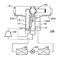
図4は実施形態に係る冷凍サイクルの概略構成図である。この冷凍サイクル100は、ルームエアコン等の空気調和機に利用されるものであって、冷媒を圧縮する圧縮機30と、冷却モード時に蒸発器として機能する一方の熱交換器としての室内熱交換器40と、冷却モード時に凝縮器として機能する他方の熱交換器としての室外熱交換器50と、室内熱交換器40と室外内熱交換器50との間にて冷媒を膨張させて減圧する膨張手段としての膨張弁60と、前記実施形態の切換弁10と、前記パイロット弁20と、を備え、これらが冷媒配管によって連結されている。なお、膨張手段としては、膨張弁60に限らず、キャピラリでもよい。
FIG. 4 is a schematic configuration diagram of a refrigeration cycle according to the embodiment. The
この冷凍サイクル100は、暖房運転時において、圧縮機30、切換弁10、室内熱交換器40、膨張弁60、室外熱交換器50、切換弁10及び圧縮機30の順に冷媒が流れる暖房サイクルを構成する。一方、冷房運転時において、圧縮機30、切換弁10、室外熱交換器50、膨張弁60、室内熱交換器40、切換弁10及び圧縮機30の順に冷媒が流れる冷房サイクルを構成する。この暖房サイクルと冷房サイクルとの切換えは、前記のようにパイロット弁20による切換弁10の切換え動作によって行われる。
The
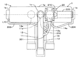
図5は本発明の第2実施形態の切換弁の正面図であり、この第2実施形態の切換弁の左側面図は図1(A)と同様である。この第2実施形態において第1実施形態との大きな違いは、D継手とパイロット弁の位置であり、第1実施形態と同じ要素及び対応する要素には同符号を付記して重複する説明は省略する。この第2実施形態では、D継手11の接続端部11aはS継手12の接続端部12aと同軸にして配置されている。すなわち、E継手13とC継手14はD継手11に対して左右対称な位置に配置されている。これにより、D継手11からE継手13に高圧冷媒を流す暖房運転時の弁ハウジング1内でのE継手13に対する冷媒の流れと、D継手11からC継手14に高圧冷媒を流す冷房運転時の弁ハウジング1内でのC継手14に対する冷媒の流れとが同様になる。したがって、暖房運転時と冷房運転時とで同等な熱効率となる。この第2実施形態でも、D継手11が、S継手12、E継手13及びC継手14と共に弁ハウジング1に対して片側に配置され、この切換弁10は小型化されたものとなる。また、D継手11の長手方向の長さが短い分だけ、高温冷媒と大気との熱交換による冷媒の温度の低下が抑制され、切換弁を小型化できるとともに、切換弁における熱ロスを低減することができる。
FIG. 5 is a front view of the switching valve of the second embodiment of the present invention, and the left side view of the switching valve of the second embodiment is the same as FIG. In the second embodiment, the major difference from the first embodiment is the position of the D joint and the pilot valve, and the same elements as those in the first embodiment and corresponding elements are denoted by the same reference numerals and redundant description is omitted. To do. In the second embodiment, the connection end 11 a of the D joint 11 is arranged coaxially with the connection end 12 a of the S joint 12. That is, the E joint 13 and the C joint 14 are arranged at positions symmetrical with respect to the D joint 11. Thereby, the flow of the refrigerant to the E joint 13 in the valve housing 1 during the heating operation in which the high pressure refrigerant flows from the D joint 11 to the E joint 13, and the cooling operation in which the high pressure refrigerant flows from the D joint 11 to the C joint 14. The flow of the refrigerant with respect to the C joint 14 in the valve housing 1 is the same. Therefore, the thermal efficiency is equivalent between the heating operation and the cooling operation. Also in the second embodiment, the D joint 11 is disposed on one side with respect to the valve housing 1 together with the S joint 12, the E joint 13, and the C joint 14, and the switching
また、この第2実施形態では、D継手11とS継手13が同軸に配置されているので、パイロット弁20は第1実施形態の場合よりもS継手14側にずらした位置に配置されているが、パイロット弁20は弁ハウジング1の長さ内に収まっている。したがって、第1実施形態と同様に、パイロット弁20の配置場所としてD継手11の横のデッドスペースを利用しているので、切換弁を小型化できる。
In the second embodiment, since the D joint 11 and the S joint 13 are arranged coaxially, the
以上の各実施形態において、S継手12、E継手13及びC継手14は同一直線上に配置されているが、D継手11はこの直線から離れた位置に配置されている。したがって、D継手11、S継手12、E継手13及びC継手14で囲われる空間の、軸線L10,L1,L2,L3,L4を含む面と平行な面での断面二次モーメントが大きくなり、堅牢な切換弁10となる。また、切換弁10は、D継手11、S継手12、E継手13及びC継手14の各継手によって、全体として圧縮機30側にて片持ち支持されることになる。このため、例えば圧縮機30からの振動が弁ハウジング1に伝達されて、各継手に対して片持ち支持で振られる方向に力が加わり、その力が各継手の例えばろう付けによる円環状の接続部分に伝達されても、軸線L1,L2,L3,L4がその振れの振動方向に向いているので、この接続部分の円環状の全周において応力を同方向でかつ均等に受けることができ、この接続部分の劣化を防止することができる。
In the above embodiments, the S joint 12, the E joint 13, and the C joint 14 are arranged on the same straight line, but the D joint 11 is arranged at a position away from this straight line. Therefore, the sectional moment of inertia in the plane parallel to the plane including the axes L10, L1, L2, L3, and L4 in the space surrounded by the D joint 11, the S joint 12, the E joint 13, and the C joint 14 is increased. A
なお、第1実施形態では、D継手11の接続端部11aをE継手13の接続端部13aと同軸になるようにしているが、D継手11の接続端部11aをC継手14の接続端部14aと同軸になるようにしてもよい。この場合には、冷房運転の状態で、高圧冷媒は弁ハウジング1内においてD継手11からC継手14にストレートに流れるので、圧力損失が少なく冷凍サイクルの運転効率が良くなる。
In the first embodiment, the
また、この第2実施形態の切換弁10及びパイロット弁20も第1実施形態と同様に、前記図4の冷凍サイクルに適用できることはいうまでもない。
Needless to say, the switching
以上、本発明の実施の形態について図面を参照して詳述してきたが、具体的な構成はこれらの実施の形態に限られるものではなく、本発明の要旨を逸脱しない範囲の設計の変更等があっても本発明に含まれる。 As described above, the embodiments of the present invention have been described in detail with reference to the drawings. However, the specific configuration is not limited to these embodiments, and the design can be changed without departing from the scope of the present invention. Is included in the present invention.
1 弁ハウジング
11 D継手
11a 接続端部
12 S継手
12a 接続端部
13 E継手
13a 接続端部
14 C継手
14a 接続端部
2 弁座部材
21 弁座面
22 Sポート
23 Eポート
24 Cポート
3 ピストン
4 連結板
5 スライド弁
10 切換弁
20 パイロット弁
30 圧縮機
40 室内熱交換器(一方の熱交換器)
50 室外熱交換器(他方の熱交換器)
60 膨張弁(膨張手段)
100 冷凍サイクル
1 Valve Housing 11
50 Outdoor heat exchanger (the other heat exchanger)
60 Expansion valve (expansion means)
100 refrigeration cycle
Claims (5)
前記S継手と、前記E継手と、前記C継手と、前記D継手とを、その直管部分を同方向に向けて併設するとともに、
前記D継手の前記弁ハウジング側の接続端部を、当該D継手の前記S継手、E継手及びC継手と併設される前記直管部分に対して略直角となる方向に屈曲させて、該接続端部を該弁ハウジングに接続したことを特徴とする切換弁。 For a sealed valve housing, a D joint connected to the discharge side of the compressor, an S joint connected to the suction side of the compressor, an E joint connected to one heat exchanger, and the other And the C joint connected to the heat exchanger are respectively conducted, and the E joint or the C joint is selectively switched to the S joint by a slide valve disposed in the valve housing. In the switching valve in which the C joint or E joint that is non-conductive to the S joint is made to conduct to the D joint through the valve housing,
The S joint, the E joint, the C joint, and the D joint, with the straight pipe portion facing in the same direction,
The connection end of the D joint on the valve housing side is bent in a direction substantially perpendicular to the straight pipe portion provided along with the S joint, E joint, and C joint of the D joint. A switching valve having an end connected to the valve housing.
前記S継手、E継手及びC継手の前記弁ハウジング側の接続端部を、当該S継手、E継手及びC継手の前記D継手と平行な前記直管部分に対して、略直角となる方向に屈曲させて、前記Sポート及び2つの切換ポートにそれぞれ接続したことを特徴とする請求項1に記載の切換弁。 A valve seat member formed with an S port connected to the S joint and two switching ports respectively connected to the E joint and the C joint is disposed in the valve housing, and the valve The valve seat surface facing the slide valve of the seat member is disposed so as to be orthogonal to the axis of the connection end of the D joint,
The connection end on the valve housing side of the S joint, E joint, and C joint is in a direction that is substantially perpendicular to the straight pipe portion parallel to the D joint of the S joint, E joint, and C joint. The switching valve according to claim 1, wherein the switching valve is bent and connected to the S port and the two switching ports.
前記パイロット弁を、前記弁ハウジングの軸方向において前記D継手の前記接続端部と併設して配置されていることを特徴とする請求項1乃至3のいずれか一項に記載の切換弁。 A pilot valve for switching the slide valve using a pressure difference between the high pressure fluid of the D joint and the low pressure fluid of the S joint;
4. The switching valve according to claim 1, wherein the pilot valve is disposed side by side with the connection end portion of the D joint in the axial direction of the valve housing. 5.
前記切換弁は、
前記圧縮機で圧縮した冷媒を前記D継手から前記弁ハウジングの内部に流入させるとともに、前記C継手を介して前記他方の熱交換器へ冷媒を流出させ、前記一方の熱交換器から前記E継手に流入した冷媒を前記S継手から前記圧縮機に還流させるか、
又は、
前記圧縮機で圧縮した冷媒を前記D継手から前記弁ハウジングの内部に流入させるとともに、前記E継手を介して前記一方の熱交換器へ冷媒を流出させ、前記他方の熱交換器から前記C継手に流入した冷媒を前記S継手から前記圧縮機に還流させる
ことを特徴とする冷凍サイクルシステム。 The compressor which compresses the refrigerant | coolant which is a fluid, the expansion means which expands and decompresses a refrigerant | coolant between said one heat exchanger and said other heat exchanger, and any one of Claims 1 thru | or 4 A switching valve according to claim 1,
The switching valve is
The refrigerant compressed by the compressor is caused to flow from the D joint into the valve housing, and the refrigerant is caused to flow out to the other heat exchanger via the C joint, from the one heat exchanger to the E joint. Or recirculates the refrigerant flowing into the compressor from the S joint to the compressor,
Or
The refrigerant compressed by the compressor is caused to flow into the valve housing from the D joint, and the refrigerant is caused to flow out to the one heat exchanger via the E joint, and from the other heat exchanger to the C joint. The refrigerant flowing into the refrigerant is recirculated from the S joint to the compressor.
Priority Applications (2)
| Application Number | Priority Date | Filing Date | Title |
|---|---|---|---|
| JP2015116043A JP6329513B2 (en) | 2015-06-08 | 2015-06-08 | Switching valve and refrigeration cycle system |
| CN201610352642.7A CN106247701B (en) | 2015-06-08 | 2016-05-25 | Switching valve and refrigerating circulation system |
Applications Claiming Priority (1)
| Application Number | Priority Date | Filing Date | Title |
|---|---|---|---|
| JP2015116043A JP6329513B2 (en) | 2015-06-08 | 2015-06-08 | Switching valve and refrigeration cycle system |
Publications (2)
| Publication Number | Publication Date |
|---|---|
| JP2017002965A true JP2017002965A (en) | 2017-01-05 |
| JP6329513B2 JP6329513B2 (en) | 2018-05-23 |
Family
ID=57626618
Family Applications (1)
| Application Number | Title | Priority Date | Filing Date |
|---|---|---|---|
| JP2015116043A Active JP6329513B2 (en) | 2015-06-08 | 2015-06-08 | Switching valve and refrigeration cycle system |
Country Status (2)
| Country | Link |
|---|---|
| JP (1) | JP6329513B2 (en) |
| CN (1) | CN106247701B (en) |
Cited By (1)
| Publication number | Priority date | Publication date | Assignee | Title |
|---|---|---|---|---|
| JP2024137018A (en) * | 2023-03-24 | 2024-10-04 | 株式会社鷺宮製作所 | Slide type switching valve |
Families Citing this family (1)
| Publication number | Priority date | Publication date | Assignee | Title |
|---|---|---|---|---|
| JP7738674B2 (en) * | 2021-05-20 | 2025-09-12 | 浙江盾安人工環境股▲ふん▼有限公司 | Reversible solenoid valve and air conditioning unit having same |
Citations (6)
| Publication number | Priority date | Publication date | Assignee | Title |
|---|---|---|---|---|
| JPS52152422U (en) * | 1976-05-17 | 1977-11-18 | ||
| US4213483A (en) * | 1978-11-13 | 1980-07-22 | Robertshaw Controls Company | Reversing valve construction and parts therefor and methods of making the same |
| JPS55110861A (en) * | 1979-02-20 | 1980-08-26 | Matsushita Electric Industrial Co Ltd | Heat pump type refrigerating plant |
| JP2001116404A (en) * | 1999-10-13 | 2001-04-27 | Izumi Giken:Kk | Accumulator |
| JP2011047530A (en) * | 2009-08-25 | 2011-03-10 | Hitachi Appliances Inc | Air conditioner |
| JP2015068501A (en) * | 2013-09-27 | 2015-04-13 | 浙江三花制冷集団有限公司 | Four-way selector valve and its main valve |
-
2015
- 2015-06-08 JP JP2015116043A patent/JP6329513B2/en active Active
-
2016
- 2016-05-25 CN CN201610352642.7A patent/CN106247701B/en active Active
Patent Citations (6)
| Publication number | Priority date | Publication date | Assignee | Title |
|---|---|---|---|---|
| JPS52152422U (en) * | 1976-05-17 | 1977-11-18 | ||
| US4213483A (en) * | 1978-11-13 | 1980-07-22 | Robertshaw Controls Company | Reversing valve construction and parts therefor and methods of making the same |
| JPS55110861A (en) * | 1979-02-20 | 1980-08-26 | Matsushita Electric Industrial Co Ltd | Heat pump type refrigerating plant |
| JP2001116404A (en) * | 1999-10-13 | 2001-04-27 | Izumi Giken:Kk | Accumulator |
| JP2011047530A (en) * | 2009-08-25 | 2011-03-10 | Hitachi Appliances Inc | Air conditioner |
| JP2015068501A (en) * | 2013-09-27 | 2015-04-13 | 浙江三花制冷集団有限公司 | Four-way selector valve and its main valve |
Cited By (2)
| Publication number | Priority date | Publication date | Assignee | Title |
|---|---|---|---|---|
| JP2024137018A (en) * | 2023-03-24 | 2024-10-04 | 株式会社鷺宮製作所 | Slide type switching valve |
| JP7781096B2 (en) | 2023-03-24 | 2025-12-05 | 株式会社鷺宮製作所 | Slide-type switching valve |
Also Published As
| Publication number | Publication date |
|---|---|
| CN106247701A (en) | 2016-12-21 |
| JP6329513B2 (en) | 2018-05-23 |
| CN106247701B (en) | 2018-10-23 |
Similar Documents
| Publication | Publication Date | Title |
|---|---|---|
| JP6407844B2 (en) | Switching valve and refrigeration cycle | |
| JP6261008B2 (en) | Sliding switching valve and refrigeration cycle system | |
| CN104964490B (en) | Four-way valve and air-conditioning system | |
| JP5870760B2 (en) | Four-way valve and heat pump device equipped with it | |
| CN109973682B (en) | Electromagnetic directional valve and refrigeration system with same | |
| WO2016192146A1 (en) | Six-way reversing valve, and air-conditioning outdoor unit, and air conditioner having same | |
| CN104896612A (en) | Air conditioning outdoor unit and air conditioner | |
| CN104896143A (en) | Six-way reversing valve and air conditioning outdoor unit and air conditioner with same | |
| JP6426644B2 (en) | Sliding type switching valve and refrigeration cycle system | |
| JP6329513B2 (en) | Switching valve and refrigeration cycle system | |
| JP5982871B2 (en) | Four-way valve and heat pump device equipped with it | |
| JP6254980B2 (en) | Sliding switching valve and refrigeration cycle system | |
| JP6832299B2 (en) | Sliding switching valve and refrigeration cycle system equipped with it | |
| JP5663330B2 (en) | Four-way selector valve | |
| JP2014055748A (en) | Internal heat exchanger and method for producing the same | |
| JP6670208B2 (en) | Slide valve and refrigeration cycle system | |
| WO2016192147A1 (en) | Air-conditioning outdoor unit and air conditioner | |
| CN101319734B (en) | Piston connecting rod of four-way reversing valve | |
| CN104235462B (en) | Electromagnetism four-way reversing valve | |
| JP6069921B2 (en) | Four-way valve | |
| US20220146159A1 (en) | Refrigeration apparatus | |
| CN204757182U (en) | Air condensing units and air conditioner | |
| CN216407808U (en) | An electromagnetic reversing valve | |
| JP7569815B2 (en) | Slide type switching valve and refrigeration cycle system | |
| JP2008170042A (en) | Air conditioner |
Legal Events
| Date | Code | Title | Description |
|---|---|---|---|
| A621 | Written request for application examination |
Free format text: JAPANESE INTERMEDIATE CODE: A621 Effective date: 20170202 |
|
| A977 | Report on retrieval |
Free format text: JAPANESE INTERMEDIATE CODE: A971007 Effective date: 20171110 |
|
| A131 | Notification of reasons for refusal |
Free format text: JAPANESE INTERMEDIATE CODE: A131 Effective date: 20171128 |
|
| A521 | Request for written amendment filed |
Free format text: JAPANESE INTERMEDIATE CODE: A523 Effective date: 20180115 |
|
| RD04 | Notification of resignation of power of attorney |
Free format text: JAPANESE INTERMEDIATE CODE: A7424 Effective date: 20180119 |
|
| TRDD | Decision of grant or rejection written | ||
| A01 | Written decision to grant a patent or to grant a registration (utility model) |
Free format text: JAPANESE INTERMEDIATE CODE: A01 Effective date: 20180403 |
|
| A61 | First payment of annual fees (during grant procedure) |
Free format text: JAPANESE INTERMEDIATE CODE: A61 Effective date: 20180420 |
|
| R150 | Certificate of patent or registration of utility model |
Ref document number: 6329513 Country of ref document: JP Free format text: JAPANESE INTERMEDIATE CODE: R150 |