JP2017003531A - Object detection apparatus, object removal operation control system, object detection method, and object detection program - Google Patents
Object detection apparatus, object removal operation control system, object detection method, and object detection program Download PDFInfo
- Publication number
- JP2017003531A JP2017003531A JP2015120559A JP2015120559A JP2017003531A JP 2017003531 A JP2017003531 A JP 2017003531A JP 2015120559 A JP2015120559 A JP 2015120559A JP 2015120559 A JP2015120559 A JP 2015120559A JP 2017003531 A JP2017003531 A JP 2017003531A
- Authority
- JP
- Japan
- Prior art keywords
- light
- illumination
- amount
- detection
- raindrop
- Prior art date
- Legal status (The legal status is an assumption and is not a legal conclusion. Google has not performed a legal analysis and makes no representation as to the accuracy of the status listed.)
- Pending
Links
Images


Landscapes
- Investigating Or Analysing Materials By Optical Means (AREA)
Abstract
【課題】検出対象物の誤検出や検出漏れを抑制することを課題とする。【解決手段】光源光の照射、非照射を周期的に繰り返す光源202による光源光の照明時に受光手段206により受光される照明時受光量に基づいて該光源光の照明範囲内における検出対象物を検出する物体検出装置において、前記光源による光源光の非照明時に前記受光手段により受光される非照明時受光量と、該非照明時受光量に対応する非照明時の直前の照明時よりも前期間における照明時受光量、及び、該非照明時受光量に対応する非照明時の直後の照明時よりも後期間における照明時受光量の少なくとも一方の照明時受光量とを用いて、前記照明範囲内における検出対象物の存在状況を検出するための所定の条件を満たすか否かを判断する検出処理を実行する検出処理手段102Aを有する。【選択図】図2PROBLEM TO BE SOLVED: To suppress erroneous detection and omission of detection of a detection object. SOLUTION: A detection target within the illumination range of the light source light is detected based on the amount of light received by the light receiving means 206 when the light source light is illuminated by the light source 202 that periodically repeats irradiation and non-irradiation of the light source light. In the object detection device for detection, the amount of light received by the light receiving means when the light from the light source is not illuminated by the light source and the amount of light received during non-illumination are the period prior to the time of lighting immediately before the time of non-illumination corresponding to the amount of light received during non-illumination. The amount of light received during illumination and the amount of light received during illumination at least one of the amount of light received during illumination in a period after the time of illumination immediately after the time of non-illumination corresponding to the amount of light received during non-illumination are within the illumination range. The detection processing means 102A for executing the detection process for determining whether or not a predetermined condition for detecting the existence status of the detection target in the above conditions is satisfied is provided. [Selection diagram] Fig. 2
Description
本発明は、物体検出装置、物体除去動作制御システム、物体検出方法及び物体検出用プログラムに関するものである。 The present invention relates to an object detection device, an object removal operation control system, an object detection method, and an object detection program.
従来、光源からの光源光で照明される照明範囲内の検出対象物を画像センサ等の受光手段を用いて撮像して検出対象物を検出するための検出処理を実行する物体検出装置が知られている。 2. Description of the Related Art Conventionally, an object detection device that performs detection processing for detecting a detection target by imaging a detection target within an illumination range illuminated by light from a light source using a light receiving unit such as an image sensor is known. ing.
例えば、特許文献1には、光源が照射した光源光によって照明された自動車のフロントガラス(光透過性部材)からの反射光を画像センサの雨滴検出領域で受光して撮像し、フロントガラス上に付着している雨滴を検出するための雨滴検出処理を実行する雨滴検出装置が開示されている。この雨滴検出装置は、雨滴の検出精度を低下させる光源光以外の外乱光の影響を抑制するため、光源光の点灯(照射)、消灯(非照射)を周期的に繰り返し、光源の点灯時に撮像した点灯時画像と光源の消灯時に撮像した消灯時画像との差分情報を用いて雨滴検出処理を行う。そして、この雨滴検出処理で雨滴が検出された場合、ワイパーを作動させるなどの制御を実施する。特許文献1によれば、消灯時画像は外乱光のみを映し出すものであるため、点灯時画像から消灯時画像を差し引いて得られる差分情報は、点灯時画像から外乱光成分を除外したものとなる。このような差分情報を用いて雨滴検出処理を行うことにより、外乱光の影響を抑制した雨滴検出処理が可能となるとされている。
For example, in
また、前記差分情報を用いて雨滴検出処理を行う場合、わずかの時間経過で大きく外乱光が変化する状況だと、点灯時画像と消灯時画像との間で外乱光成分が異なってしまう。その結果、前記差分情報が、点灯時画像から外乱光成分を適切に除外したものにはならず、雨滴検出処理において、雨滴の誤検出あるいは雨滴の検出漏れが引き起こされ得る。そのため、特許文献1に開示の雨滴検出装置では、点灯時画像の前後で撮像される2つの消灯時画像間における差分値を算出し、この消灯時画像差分値が閾値を超えている場合には、わずかの時間経過で大きく外乱光が変化する状況であると判断し、前記差分情報を用いた雨滴検出処理を中止する。
Further, when the raindrop detection process is performed using the difference information, the disturbance light component differs between the on-time image and the off-time image if the disturbance light changes greatly after a short time. As a result, the difference information does not appropriately exclude disturbance light components from the on-light image, and in the raindrop detection process, erroneous detection of raindrops or missed detection of raindrops may be caused. For this reason, the raindrop detection device disclosed in
一般に、画像センサには、自動露光補正機能やレベル補正機能などの自動補正機能が備わっており、このような自動補正機能が実施されると、画像センサの受光量が同じであっても、画像センサの出力値が変化する。したがって、雨滴の付着状態が全く同じであっても、自動補正機能によって、点灯時画像についての画像センサの出力値は異なるものとなる。ところが、消灯時画像の出力値については、自動補正機能によってもほぼ変化しない場合がある。そのため、特許文献1に開示の雨滴検出装置では、雨滴の付着状態が全く同じであっても、自動補正機能によって、点灯時画像と消灯時画像との差分情報が変化してしまい、雨滴の誤検出あるいは雨滴の検出漏れを引き起こすおそれがある。しかも、このときには、点灯時画像の前後で撮像される2つの消灯時画像間における差分値はほぼゼロであるため、雨滴検出処理が中止されることもない。
In general, an image sensor is provided with an automatic correction function such as an automatic exposure correction function and a level correction function. When such an automatic correction function is performed, even if the received light amount of the image sensor is the same, the image sensor The output value of the sensor changes. Therefore, even if the raindrops are attached in exactly the same state, the output value of the image sensor for the lighting image will be different due to the automatic correction function. However, the output value of the image when it is turned off may not change substantially even by the automatic correction function. For this reason, in the raindrop detection device disclosed in
この課題は、差分情報を用いて検出対象物の存在状況を検出する場合に限らず、少なくとも照明時受光量を用いて検出対象物の存在状況を検出する際に、外乱光や自動補正機能による誤検出や検出漏れを非照明時受光量によって把握して検出処理を中止するなどの対処を行う場合には、同様に生じ得る。 This problem is not limited to detecting the presence state of the detection object using the difference information, but at least using the ambient light and the automatic correction function when detecting the presence state of the detection object using the received light amount during illumination. This can occur in the same manner when taking measures such as grasping erroneous detection or detection omission based on the amount of light received during non-illumination and stopping the detection process.
上述した課題を解決するために、本発明は、光源光の照射、非照射を周期的に繰り返す光源による光源光の照明時に受光手段により受光される照明時受光量に基づいて該光源光の照明範囲内における検出対象物を検出する物体検出装置において、前記光源による光源光の非照明時に前記受光手段により受光される非照明時受光量と、該非照明時受光量に対応する非照明時の直前の照明時よりも前期間における照明時受光量、及び、該非照明時受光量に対応する非照明時の直後の照明時よりも後期間における照明時受光量の少なくとも一方の照明時受光量とを用いて、前記照明範囲内における検出対象物の存在状況を検出するための所定の条件を満たすか否かを判断する検出処理を実行する検出処理手段を有することを特徴とする。 In order to solve the above-described problem, the present invention illuminates the light source light based on the amount of light received by the light receiving unit when the light source light is illuminated by the light source that periodically repeats irradiation and non-irradiation of the light source light. In the object detection apparatus for detecting a detection target within a range, the light reception amount received by the light receiving unit when the light source light is not illuminated by the light source and immediately before the non-illumination corresponding to the light reception amount during the non-illumination The amount of light received during illumination in the previous period from the time of illumination and the amount of light received during illumination corresponding to the amount of light received during non-illumination and at least one of the light reception amounts during illumination after the illumination immediately after non-illumination And a detection processing means for executing a detection process for determining whether or not a predetermined condition for detecting the presence state of the detection target in the illumination range is satisfied.
本発明によれば、検出対象物の誤検出や検出漏れを抑制することが可能となるという優れた効果が奏される。 According to the present invention, there is an excellent effect that it is possible to suppress erroneous detection and detection omission of a detection target.
〔実施形態1〕
以下、本発明に係る物体検出装置を、移動体である自動車等の車両に搭載される対象機器を制御する移動体機器制御システムとしての車載機器制御システムに用いられる付着物検出装置に適用した一実施形態(以下、本実施形態を「実施形態1」という。)について説明する。
なお、本発明に係る物体検出装置は、検出対象物の検出結果を利用して各種処理や制御を実行するシステムにおいて広く利用することができ、自動車以外の車両、船舶、航空機などの他の移動体に搭載される種々の移動体搭載機器の制御システム、あるいは、移動体に搭載される機器ではないFA(factory automation)等の処理装置の制御システムなどにも利用することができる。
Hereinafter, the object detection device according to the present invention is applied to an attached matter detection device used in an in-vehicle device control system as a mobile device control system that controls a target device mounted on a vehicle such as an automobile that is a mobile body. An embodiment (hereinafter, this embodiment is referred to as “
Note that the object detection device according to the present invention can be widely used in a system that executes various processes and controls using the detection result of the detection target, and other movements such as a vehicle other than an automobile, a ship, and an aircraft. The present invention can also be used for a control system for various mobile equipment mounted on the body or a control system for a processing apparatus such as FA (factory automation) that is not equipment mounted on the mobile body.
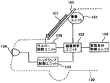
図1は、本実施形態1における車載機器制御システムの概略構成を示す模式図である。
本車載機器制御システムは、自動車などの自車両100に搭載された撮像部により、自車両周囲(特に進行方向前方領域)を撮像領域として撮像した撮像画像データを利用して、ヘッドランプの配光制御、ワイパーの駆動制御、その他の車載機器の制御を行うものである。
FIG. 1 is a schematic diagram illustrating a schematic configuration of an in-vehicle device control system according to the first embodiment.
This in-vehicle device control system uses a picked-up image data obtained by picking up an area around the own vehicle (especially a forward area in the traveling direction) by an image pickup unit mounted on the
本実施形態1の車載機器制御システムに設けられる撮像部は、撮像ユニット101に設けられており、走行する自車両100の進行方向前方領域を撮像領域として撮像するものであり、例えば、自車両100のフロントガラス105のルームミラー付近に設置される。撮像ユニット101の撮像部で撮像された撮像画像データは、画像解析ユニット102に入力される。画像解析ユニット102は、CPUやRAM等により構成され、撮像部から送信されてくる撮像画像データを解析し、撮像画像データに自車両100の前方に存在する他車両の位置(方角や距離)を算出したり、フロントガラス105に付着する雨滴や異物などの付着物(検出対象物)を検出したり、撮像領域内に存在する路面上の白線(区画線)等を検出したりする。他車両の検出では、他車両のテールランプを識別することで自車両100と同じ進行方向へ進行する先行車両を検出し、他車両のヘッドランプを識別することで自車両100とは反対方向へ進行する対向車両を検出する。
The imaging unit provided in the in-vehicle device control system according to the first embodiment is provided in the imaging unit 101, and images an area in the traveling direction of the traveling
画像解析ユニット102の算出結果は、ヘッドランプ制御ユニット103に送られる。ヘッドランプ制御ユニット103は、例えば、画像解析ユニット102が算出した他車両の位置データから、自車両100の車載機器であるヘッドランプ104を制御する制御信号を生成する。具体的には、例えば、先行車両や対向車両の運転者の目に自車両100のヘッドランプの強い光が入射するのを避けて他車両の運転者の幻惑防止を行いつつ、自車両100の運転者の視界確保を実現できるように、ヘッドランプ104のハイビームおよびロービームの切り替えを制御したり、ヘッドランプ104の部分的な遮光制御を行ったりする。
The calculation result of the
画像解析ユニット102の算出結果は、ワイパー制御ユニット106にも送られる。ワイパー制御ユニット106は、物体除去手段としてのワイパー107を制御して、自車両100のフロントガラス105に付着した雨滴や異物などの付着物(検出対象物)を除去する。ワイパー制御ユニット106は、画像解析ユニット102が検出した付着物検出結果を受けて、ワイパー107を制御する制御信号を生成する。ワイパー制御ユニット106により生成された制御信号がワイパー107に送られると、自車両100の運転者の視界を確保するべく、ワイパー107を稼動させる。
The calculation result of the
また、画像解析ユニット102の算出結果は、車両走行制御ユニット108にも送られる。車両走行制御ユニット108は、画像解析ユニット102が検出した白線検出結果に基づいて、白線によって区画されている車線領域から自車両100が外れている場合等に、自車両100の運転者へ警告を報知したり、自車両のハンドルやブレーキを制御するなどの走行支援制御を行ったりする。また、車両走行制御ユニット108は、画像解析ユニット102が検出した他車両の位置データに基づいて、先行車両との距離が近接した場合等に、自車両100の運転者へ警告を報知したり、自車両のハンドルやブレーキを制御するなどの走行支援制御を行ったりする。
The calculation result of the
図2は、撮像ユニット101に設けられる撮像部200と付着物検出装置を構成する画像解析ユニット102との概略構成を示す説明図である。
撮像部200は、主に、撮像レンズ204と、光学フィルタ205と、受光素子が2次元配置された受光手段としての画像センサ206を含んだセンサ基板207と、センサ基板207から出力されるアナログ電気信号(画像センサ206上の各受光素子が受光した受光量)をデジタル電気信号に変換した撮像画像データを生成して出力する信号処理部208とから構成されている。また、本実施形態1においては、センサ基板207上に光源装置としての光源部202が実装されている。この光源部202は、光透過性部材としてのフロントガラス105の内壁面(一方の面)側に配置され、外壁面(他方の面)に付着した付着物(以下、付着物が主に雨滴である場合を例に挙げて説明する。)を検出するためのものである。
FIG. 2 is an explanatory diagram illustrating a schematic configuration of the
The
本実施形態1では、撮像レンズ204の光軸が水平方向に一致するように撮像ユニット101を配置するが、これに限定されることはなく、水平方向(図2中のX方向)を基準とした特定方向に向けるような例であってもよい。撮像レンズ204は、例えば、複数のレンズで構成され、焦点がフロントガラス105の位置よりも遠方に設定されるものを用いる。撮像レンズ204の焦点位置は、例えば、無限遠又は無限遠とフロントガラス105との間に設定することができる。
In the first embodiment, the imaging unit 101 is arranged so that the optical axis of the
画像センサ206は、センサ面を保護するカバーガラスを透過した光を受光する2次元配置された複数の受光素子で構成され、受光素子(撮像画素)ごとに入射光を光電変換する機能を有する。後述の図等では画像センサ206の各画素を簡略化して描いているが、実際には画像センサ206は2次元配置された数十万個程度の画素で構成されている。画像センサ206としては、例えば、全撮像画素を同時露光(グローバルシャッター)して各撮像画素の信号を読み出すCCD(Charge Coupled Device)や、ライン露光(ローリングシャッター)で露光された各撮像画素の信号を読み出すCMOS(Complementary Metal Oxide Semiconductor)などを用いたイメージセンサであり、その受光素子にはフォトダイオードを用いることができる。
The
信号処理部208は、画像センサ206で光電変換され、センサ基板207から出力されるアナログ電気信号(画像センサ206の各受光素子への入射光量)をデジタル電気信号に変換した撮像画像データを生成して出力する機能を有する。信号処理部208は、画像解析ユニット102と電気的に接続されている。信号処理部208は、センサ基板207を経由して画像センサ206から電気信号(アナログ信号)が入力されると、入力された電気信号から、画像センサ206上における各撮像画素の明るさ(輝度)を示すデジタル信号(撮像画像データ)を生成する。そして、この撮像画像データを、画像の水平・垂直同期信号とともに、後段の画像解析ユニット102へ出力する。
The
本実施形態の画像センサ206は、レベル補正機能の一種であるダーク補正を行うための複数のオプティカルブラック(光が入射しないように構成された受光素子)を、有効撮像画素の領域外に備えている。オプティカルブラックの出力信号は、信号処理部208に送られ、暗電流のノイズ量の測定に使用される。詳しくは、信号処理部208は、ゼロ基準設定手段として機能し、例えばオプティカルブラックからの出力信号の平均レベルに所定のマージン分を上乗せした信号レベルを、撮像画像データのゼロ基準(画素値ゼロ)に設定する。これにより、センサ基板207から出力されるアナログ電気信号は、全体的に信号レベルが下げられ、ゼロ基準に対応する信号レベル以下のものはゼロ値とされる。ゼロ基準に対応する信号レベルを超えるアナログ電気信号は、当該ゼロ基準の信号レベルと最大信号レベルとの間を所定の階調数で分割したデジタル値のデジタル電気信号に変換される。これにより、画像センサ206の受光素子を流れる暗電流が原因で、全く光を受光していない受光素子が光を受光しているものと誤検知してしまう事態を回避することができる。
The
また、画像解析ユニット102は、撮像ユニット101の撮像動作を制御する機能や、撮像ユニット101から送信される撮像画像データを解析する機能を有する。画像解析ユニット102は、露光量制御手段としての露光量制御部102Cによって、撮像ユニット101から送信された撮像画像データから、画像センサ206の撮像対象(自車両前方領域に存在する他車両等の物体)ごとの最適な露光量を算出し、画像センサ206の撮像対象ごとに最適な露光量(本実施形態1では露光時間)を設定する自動露光補正機能を有する。また、画像解析ユニット102は、信号処理部208からの画像信号の取得と連動しながら、光源制御手段としての光源制御部102Bによって、光源部202の発光タイミングなどを制御する機能を有する。また、画像解析ユニット102は、撮像ユニット101から送信されてくる撮像画像データから、路面状態や道路標識などに関する情報を検出する機能を有する。また、画像解析ユニット102は、撮像ユニット101から送信されてくる撮像画像データから、自車両の前方に存在する他車両の位置や方角、距離等を算出する機能を有する。
Further, the
また、画像解析ユニット102は、検出処理部102Aによって、フロントガラス105の状態(雨滴の付着、凍結、曇りなど)を検出する機能を有する。検出処理部102Aは、雨滴の付着を検出する場合、撮像ユニット101から送信された撮像画像データを用い、その撮像画像データの輝度値(画素値)に応じてフロントガラス105上の雨滴量を算出する。また、画像解析ユニット102は、詳しくは後述するが、撮像ユニット101から送信されてくる撮像画像データあるいは当該撮像画像データを用いた各種処理の結果などを一時的に記憶するための記憶部102Dを備えている。
Further, the
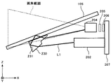
図3は、本実施形態1における撮像ユニット101の光学系を説明するための説明図である。
本実施形態1の光源部202は、フロントガラス105上に付着した付着物(雨滴、凍結、曇り等)を検出するための光源光(照明光)を照射するものである。本実施形態1の光源部202は、その光源としてのLEDを複数備え、各LEDから照射される光源光をコリメータレンズ等の光学系を通じて外部へ出射する構成となっている。このように光源を複数具備することにより、光源が1つである場合と比較して、フロントガラス105上の付着物を検出するための検出領域が広がり、フロントガラス105の付着物の検出精度が向上する。
FIG. 3 is an explanatory diagram for explaining an optical system of the imaging unit 101 according to the first embodiment.
The
本実施形態1では、LEDを画像センサ206と同じセンサ基板207上に実装しているので、これらを別々の基板上に実装する場合よりも基板枚数を減らすことができ、低コストを実現できる。また、LEDの配置方法は、図3中のY方向に沿って1列又は複数列に配置することで、後述するとおり、車両前方領域の画像が映し出される画像領域の下側に映し出されるフロントガラス画像を撮像するための照明を均一化することが可能となる。本実施形態1では、光源部202を、画像センサ206と同じセンサ基板207上に実装しているが、画像センサ206とは別基板上に実装してもよい。
In the first embodiment, since the LEDs are mounted on the
光源部202は、光源部202が照射する光の光軸方向と撮像レンズ204の光軸方向とが予め所定の角度を有するように、センサ基板207上に配置されている。また、光源部202は、光源部202が照射する光によって照明されるフロントガラス105上において、その照明範囲が撮像レンズ204の画角範囲内(視野角の範囲内)となるように、配置されている。光源部202の発光波長としては、対向車の運転者や歩行者を眩惑しないように、可視光を避けることが好ましく、例えば、可視光よりも波長が長く、画像センサ206の受光感度が及ぶ波長範囲(例えば800〜1000nm程度の赤外光波長範囲)を用いる。光源部202の発光タイミングなどの駆動制御は、信号処理部208からの画像信号の取得と連動しながら、画像解析ユニット102の光源制御部102Bによって行われる。
The
本実施形態1の撮像ユニット101には、図3に示すように、光源部202からの光を反射させてフロントガラス105へ導く反射面231を備えた反射偏向プリズム230が設けられている。反射偏向プリズム230は、光源部202からの光を適切にフロントガラス105の内部に導くために、その一面がフロントガラス105の内壁面に密着するように配置されている。具体的には、反射偏向プリズム230に入射する光源部202からの光の入射角が所定範囲内で変化しても、光源部202から照射されて反射偏向プリズム230の反射面231で正反射した光のうち、フロントガラス105の外壁面上における雨滴(検出対象物)が付着していない非付着箇所で正反射した正反射光が、画像センサ206に受光される関係が維持されるように、反射偏向プリズム230がフロントガラス105の内壁面に取り付けられる。
As shown in FIG. 3, the imaging unit 101 according to the first embodiment is provided with a
反射偏向プリズム230をフロントガラス105の内壁面に取り付ける際、これらの間に、透光性材料からなるジェルやシール材などの充填材を介在させて密着性を高めるのが好ましい。これにより、反射偏向プリズム230とフロントガラス105との間に空気層や気泡などが介在しないようにでき、これらの間で曇りが生じにくいようにしている。また、充填材の屈折率は、反射偏向プリズム230とフロントガラス105の中間屈折率であることが好ましい。これにより、充填材と反射偏向プリズム230との間、及び、充填材とフロントガラス105との間でのフレネル反射ロスを軽減できるからである。ここでいうフレネル反射とは、屈折率の異なる材料間で発生する反射のことである。
When the
反射偏向プリズム230は、図3に示すように、光源部202からの入射光を反射面231で一回だけ正反射して、これをフロントガラス105の内壁面に向けて折り返す。折り返した光は、フロントガラス105の外壁面に対して入射角θ(θ≧約42°)となるように構成されている。この適切な入射角θは、空気とフロントガラス105の外壁面との間の屈折率差に起因して、フロントガラス105の内部においてその外壁面で全反射を起こす臨界角である。したがって、本実施形態1では、フロントガラス105の外壁面に雨滴等の付着物が付着していない場合には、反射偏向プリズム230の反射面で折り返された光は、フロントガラス105の外壁面を透過することなく、すべて反射される。
As shown in FIG. 3, the
一方、フロントガラス105の外壁面上に空気(屈折率1)とは異なる雨滴(屈折率1.38)などの付着物が付着すると、この全反射条件が崩れ、雨滴が付着している箇所では光がフロントガラス105の外壁面を透過する。したがって、フロントガラス105の外壁面に雨滴が付着していない非付着箇所については、その反射光が画像センサ206に受光されて高輝度な画像部分となる一方、雨滴が付着している付着箇所については、その反射光の光量が減り、画像センサ206に受光される光量が少なくなるので、低輝度な画像部分となる。したがって、撮像画像上においては、雨滴付着箇所と非雨滴付着箇所とのコントラストが得られる。
On the other hand, if deposits such as raindrops (refractive index 1.38) different from air (refractive index 1) adhere on the outer wall surface of the
図4は、本実施形態1の撮像ユニット101の概略構成を模式的に示した斜視図である。
本実施形態1の撮像ユニット101は、反射偏向プリズム230を固定支持し、フロントガラス105の内壁面に固定配置される第一支持部材としての第一モジュール101Aと、画像センサ206及びLED211が実装されたセンサ基板207、導光体215、撮像レンズ204を固定支持する第二支持部材としての第二モジュール101Bとから構成されている。
FIG. 4 is a perspective view schematically showing a schematic configuration of the imaging unit 101 of the first embodiment.
The imaging unit 101 of the first embodiment is mounted with a
これらのモジュール101A,101Bは、回転連結機構240によって回動可能に連結されている。この回転連結機構240は、フロントガラス105の傾斜方向及び鉛直方向のいずれにも直交する方向(図3中紙面前後方向)に延びる回転軸241を有し、この回転軸241を中心にして、第一モジュール101Aと第二モジュール101Bとを相対回転させることができる。このように回動可能な構成としているのは、傾斜角度が異なるフロントガラス105に対して第一モジュール101Aが固定配置される場合でも、第二モジュール101Bの撮像部200の撮像方向を目標とする特定方向(本実施形態1では水平方向)に向けることができるようにするためである。
These modules 101 </ b> A and 101 </ b> B are rotatably connected by a rotation connecting mechanism 240. The rotation coupling mechanism 240 has a
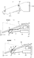
図5(a)は、水平面に対するフロントガラス105の傾斜角度θgが22°である車両に取り付けた状態の撮像ユニット101を示す側面図である。図5(b)は、図5(a)の状態において雨滴が付着していない場合の撮像ユニット101の光学系を示す説明図である。図5(c)は、図5(a)の状態において雨滴が付着している場合の撮像ユニット101の光学系を示す説明図である。
FIG. 5A is a side view showing the imaging unit 101 in a state of being attached to a vehicle in which the
光源部202からの光L1は、反射偏向プリズム230の反射面231で正反射され、その反射光L2はフロントガラス105の内壁面を透過する。フロントガラス105の外壁面に雨滴が付着していない場合は、その反射光L2は外壁面では全反射し、この反射光L3はフロントガラス105の内壁面を透過して撮像レンズ204に向けて光は進む。一方、フロントガラス105の外壁面に雨滴203が付着している場合、反射偏向プリズム230の反射面231で正反射した反射光L2は、その外壁面を透過する。このような系において、フロントガラス105の角度θgが変わると、第二モジュール101Bの姿勢を維持したまま(撮像方向を水平方向に固定したまま)、フロントガラス105の内壁面に固定される第二モジュール101Bの姿勢が変化し、反射偏向プリズム230がフロントガラス105と一体になって図中Y軸回りに回転することになる。
The light L1 from the
ここで、本実施形態1における反射偏向プリズム230の反射面231とフロントガラス105の外壁面との配置関係は、回転連結機構240の回転調整範囲内において、常に、フロントガラス105の外壁面での全反射光L3が、フロントガラス状態変化検出用の画像センサ206の受光領域(以下「付着物検出用受光領域」という。)に受光される関係となっている。したがって、フロントガラス105の角度θgが変わっても、フロントガラス105の外壁面での全反射光L3が画像センサ206の付着物検出用受光領域に受光され、適切な雨滴検出を実現できる。
Here, the arrangement relationship between the reflecting
特に、本実施形態1における配置関係は、回転連結機構240の回転調整範囲内において実質的にコーナーキューブの原理が成立するような関係となっている。そのため、フロントガラス105の角度θgが変わっても、フロントガラス105の外壁面での全反射光L3の光軸方向と水平面とのなす角度θは実質的に一定である。よって、画像センサ206の付着物検出用受光領域内におけるフロントガラス105の外壁面での全反射光L3の光軸が通過する箇所の変動を小さく抑えることができ、より適切な雨滴検出を実現できる。
In particular, the arrangement relationship in the first embodiment is such that the corner cube principle is substantially established within the rotation adjustment range of the rotary coupling mechanism 240. Therefore, even if the angle θg of the
反射偏向プリズム230の反射面231とフロントガラス105の外壁面との配置関係が互いに垂直な関係であればコーナーキューブの原理が成立するが、回転連結機構240の回転調整範囲内において実質的にコーナーキューブの原理が成立するのであれば、反射偏向プリズム230の反射面231とフロントガラス105の外壁面との配置関係は互いに垂直な関係である場合に限られない。反射偏向プリズム230の反射面231とフロントガラス105の外壁面との配置関係が互いに垂直な関係でなくても、反射偏向プリズム230の他の面(被入射面や出射面)の角度を調整することにより、フロントガラス105の傾斜角度θgが変わっても、撮像レンズへ向かう全反射光L3の光軸の角度θを略一定に保持することが可能である。
The corner cube principle is established if the arrangement relationship between the
図6は、本実施形態1の反射偏向プリズム230を示す斜視図である。
反射偏向プリズム230は、光源部202からの光が入射する被入射面233と、被入射面233から入射した光L1を反射させる反射面231と、フロントガラス105の内壁面と密着する密着面232と、フロントガラス105の外壁面で反射した反射光L3を撮像部200に向けて出射する出射面234とを備えている。本実施形態1では、被入射面233と出射面234とは互いに平行な面となるように構成されているが、両者を非平行な面としてもよい。
FIG. 6 is a perspective view showing the
The
反射偏向プリズム230の材料は、少なくとも光源部202からの光を透過させる材料であればよく、ガラスやプラスチックなどを用いることができる。本実施形態1の光源部202からの光は赤外光であるため、反射偏向プリズム230の材料としては、可視光を吸収するような黒色系の材料を用いてもよい。可視光を吸収する材料を用いることにより、反射偏向プリズム230にLEDからの光(赤外光)以外の光(車外からの可視光など)が入射するのを抑制できる。
The material of the
また、反射偏向プリズム230は、回転連結機構240の回転調整範囲内において、その反射面231で光源部202からの光を全反射させる全反射条件が満たされるように形成される。また、回転連結機構240の回転調整範囲内において反射面231で全反射させる条件を満たすことが難しい場合には、反射偏向プリズム230の反射面231に、アルミニウムなどの膜を蒸着させるなどして、反射ミラーを形成してもよい。
Further, the
また、本実施形態1では、反射面231が平面であるが、反射面を凹面としたものでもよい。このような凹面状の反射面を用いることで、反射面に入射してくる拡散光束を平行化することができる。このことにより、フロントガラス105上での照度低下を抑制することが可能となる。
In the first embodiment, the reflecting
ここで、フロントガラス105の外壁面で反射した光源部202からの赤外波長光を撮像部200で撮像する際、撮像部200の画像センサ206では、光源部202からの赤外波長光のほか、例えば太陽光などの赤外波長光を含む大光量の外乱光も受光される。よって、光源部202からの赤外波長光をこのような大光量の外乱光と区別するためには、光源部202の発光量を外乱光よりも十分に大きくする必要があるが、このような大発光量の光源部202を用いることは困難である場合が多い。
Here, when imaging the infrared wavelength light from the
そこで、本実施形態1においては、例えば、図7に示すように光源部202の発光波長よりも短い波長の光をカットするようなカットフィルタか、もしくは、図8に示すように透過率のピークが光源部202の発光波長とほぼ一致したバンドパスフィルタを介して、光源部202からの光を画像センサ206で受光するように構成する。これにより、光源部202の発光波長以外の光を除去して受光できるので、画像センサ206で受光される光源部202からの光量は、外乱光に対して相対的に大きくなる。その結果、大発光量の光源部202でなくても、光源部202からの光を外乱光と区別することが可能となる。
Therefore, in the first embodiment, for example, a cut filter that cuts light having a wavelength shorter than the light emission wavelength of the
ただし、本実施形態1においては、撮像画像データから、フロントガラス105上の雨滴203を検出するだけでなく、先行車両や対向車両の検出や白線の検出も行う。そのため、撮像画像全体について光源部202が照射する赤外波長光以外の波長帯を除去してしまうと、先行車両や対向車両の検出や白線の検出に必要な波長帯の光を画像センサ206で受光できず、これらの検出に支障をきたす。そこで、本実施形態1では、撮像画像データの画像領域を、フロントガラス105上の雨滴203を検出するための雨滴検出用画像領域と、先行車両や対向車両の検出や白線の検出を行うための車両検出用画像領域とに区分し、雨滴検出用画像領域に対応する部分についてのみ光源部202が照射する赤外波長光以外の波長帯を除去するフィルタを、光学フィルタ205に配置している。
However, in the first embodiment, not only the
図9は、光学フィルタ205に設けられる前段フィルタ210の正面図である。
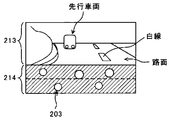
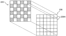
図10は、撮像画像データの画像例を示す説明図である。
本実施形態1の光学フィルタ205は、前段フィルタ210と後段フィルタ220とを光透過方向に重ね合わせた構造となっている。前段フィルタ210は、図9に示すように、車両検出用画像領域213である撮像画像上部2/3に対応する箇所に配置される赤外光カットフィルタ領域211と、雨滴検出用画像領域214である撮像画像下部1/3に対応する箇所に配置される赤外光透過フィルタ領域212とに、領域分割されている。赤外光透過フィルタ領域212には、図7に示したカットフィルタや図8に示したバンドパスフィルタを用いる。
FIG. 9 is a front view of the front-
FIG. 10 is an explanatory diagram illustrating an example of captured image data.
The
対向車両のヘッドランプ及び先行車両のテールランプ並びに白線の画像は、主に撮像画像中央部から上部に存在することが多く、撮像画像下部には自車両前方の直近路面の画像が存在するのが通常である。よって、対向車両のヘッドランプ及び先行車両のテールランプ並びに白線の識別に必要な情報は撮像画像上部に集中しており、その識別において撮像画像下部の情報はあまり重要でない。よって、単一の撮像画像データから、対向車両や先行車両あるいは白線の検出と雨滴の検出とを両立して行う場合には、図10に示すように、撮像画像下部を雨滴検出用画像領域214とし、残りの撮像画像上部を車両検出用画像領域213とし、これに対応して前段フィルタ210を領域分割するのが好適である。
The headlamp of the oncoming vehicle, the tail lamp of the preceding vehicle, and the white line image are often present mainly from the center to the upper part of the captured image, and there is usually an image of the nearest road surface in front of the host vehicle at the lower part of the captured image. It is. Therefore, the information necessary for identifying the head lamp of the oncoming vehicle, the tail lamp of the preceding vehicle, and the white line is concentrated on the upper portion of the captured image, and the information on the lower portion of the captured image is not so important in the identification. Therefore, when both oncoming vehicle and preceding vehicle or white line detection and raindrop detection are performed simultaneously from a single captured image data, the lower portion of the captured image is displayed in the raindrop
なお、本実施形態1では、撮像画像中における車両検出用画像領域213の下部に雨滴検出用画像領域214を設けた例であるが、車両検出用画像領域213の上部に雨滴検出用画像領域214を設けたり、車両検出用画像領域213の上部と下部の両方に雨滴検出用画像領域214を設けたりしてもよい。
In the first embodiment, the raindrop
撮像部200の撮像方向を下方へ傾けていくと、撮像領域内の下部に自車両のボンネットが入り込んでくる場合がある。この場合、自車両のボンネットで反射した太陽光や先行車両のテールランプなどが外乱光となり、これが撮像画像データに含まれることで対向車両のヘッドランプ及び先行車両のテールランプ並びに白線の誤識別の原因となる。このような場合でも、本実施形態1では、撮像画像下部に対応する箇所に図7に示したカットフィルタや図8に示したバンドパスフィルタが配置されているので、ボンネットで反射した太陽光や先行車両のテールランプなどの外乱光が除去される。よって、対向車両のヘッドランプ及び先行車両のテールランプ並びに白線の識別精度が向上する。
When the imaging direction of the
なお、本実施形態1では、撮像レンズ204の特性により、撮像領域内の光景と画像センサ206上の像とでは天地が逆になる。よって、撮像画像下部を雨滴検出用画像領域214とする場合には、光学フィルタ205の前段フィルタ210の上部を図7に示したカットフィルタや図8に示したバンドパスフィルタで構成することになる。
In the first embodiment, due to the characteristics of the
ここで、先行車両を検出する際には、撮像画像上のテールランプを識別することで先行車両の検出を行うが、テールランプは対向車両のヘッドランプと比較して光量が少なく、また街灯などの外乱光も多く存在するため、単なる輝度データのみからテールランプを高精度に検出するのは困難である。そのため、テールランプの識別には分光情報を利用し、赤色光の受光量に基づいてテールランプを識別することが必要となる。そこで、本実施形態1では、後述するように、光学フィルタ205の後段フィルタ220に、テールランプの色に合わせた赤色フィルタあるいはシアンフィルタ(テールランプの色の波長帯のみを透過させるフィルタ)を配置し、赤色光の受光量を検知できるようにしている。
Here, when the preceding vehicle is detected, the preceding vehicle is detected by identifying the tail lamp on the captured image. However, the tail lamp has a smaller amount of light compared to the headlamp of the oncoming vehicle, and disturbance such as street lights. Since there is a lot of light, it is difficult to detect the tail lamp with high accuracy only from mere luminance data. Therefore, it is necessary to identify the tail lamp based on the amount of received red light using spectral information for identifying the tail lamp. Therefore, in the first embodiment, as described later, a red filter or a cyan filter (a filter that transmits only the wavelength band of the tail lamp color) that matches the color of the tail lamp is disposed in the
ただし、本実施形態1の画像センサ206を構成する各受光素子は、赤外波長帯の光に対しても感度を有するので、赤外波長帯を含んだ光を画像センサ206で受光すると、得られる撮像画像は全体的に赤みを帯びたものとなってしまう。その結果、テールランプに対応する赤色の画像部分を識別することが困難となる場合がある。そこで、本実施形態1では、光学フィルタ205の前段フィルタ210において、車両検出用画像領域213に対応する箇所を赤外光カットフィルタ領域211としている。これにより、テールランプの識別に用いる撮像画像データ部分から赤外波長帯が除外されるので、テールランプの識別精度が向上する。
However, since each light receiving element constituting the
図11は、車両検出用画像領域213に対応する部分の光学フィルタ205と画像センサ206とを光透過方向に対して直交する方向から見たときの模式拡大図である。
画像センサ206は、上述したようにCCDやCMOSなどを用いたイメージセンサであり、その受光素子にはフォトダイオード206Aを用いている。フォトダイオード206Aは、画素ごとに2次元的にアレイ配置されており、フォトダイオード206Aの集光効率を上げるために、各フォトダイオード206Aの入射側にはマイクロレンズ206Bが設けられている。この画像センサ206がワイヤボンディングなどの手法によりPWB(printed wiring board)に接合されてセンサ基板207が形成されている。
FIG. 11 is a schematic enlarged view of a portion of the
As described above, the
画像センサ206のマイクロレンズ206B側の面には、光学フィルタ205が近接配置されている。車両検出用画像領域213に対応する部分における光学フィルタ205の後段フィルタ220は、図11に示すように、透明なフィルタ基板221上に偏光フィルタ層222と分光フィルタ層223を順次形成して積層構造としたものである。偏光フィルタ層222と分光フィルタ層223は、いずれも、画像センサ206上における1つのフォトダイオード206Aに対応するように領域分割されている。
An
光学フィルタ205と画像センサ206との間に空隙がある構成としてもよいが、光学フィルタ205を画像センサ206に密着させる構成とした方が、光学フィルタ205の偏光フィルタ層222と分光フィルタ層223の各領域の境界と画像センサ206上のフォトダイオード206A間の境界とを一致させやすくなる。光学フィルタ205と画像センサ206は、例えば、UV接着剤で接合してもよいし、撮像に用いる有効画素範囲外でスペーサにより支持した状態で有効画素外の四辺領域をUV接着や熱圧着してもよい。
A configuration may be adopted in which there is a gap between the
図12は、車両検出用画像領域213に対応する部分における光学フィルタ205の偏光フィルタ層222と分光フィルタ層223の領域分割パターンを示す説明図である。
偏光フィルタ層222と分光フィルタ層223は、それぞれ、第1領域及び第2領域という2種類の領域が、画像センサ206上の1つのフォトダイオード206Aに対応して配置されたものである。これにより、画像センサ206上の各フォトダイオード206Aによって受光される受光量は、受光する光が透過した偏光フィルタ層222と分光フィルタ層223の領域の種類に応じて、偏光情報や分光情報等として取得することができる。その結果、本実施形態1によれば、車両検出用画像領域213において、一度の撮像動作により、赤色光の鉛直偏光成分画像、非分光の鉛直偏光成分画像、非分光の水平偏光成分画像という3種類の撮像画像データを得ることができる。
FIG. 12 is an explanatory diagram showing a region division pattern of the
In the
このようにして得られる赤色光の鉛直偏光成分画像は、例えば、テールランプの識別に使用することができる。赤色光の鉛直偏光成分画像は、水平偏光成分Sがカットされているので、路面に反射した赤色光や自車両100の室内におけるダッシュボードなどからの赤色光(映りこみ光)等のように水平偏光成分Sの強い赤色光による外乱要因が抑制された赤色画像を得ることができる。よって、赤色光の鉛直偏光成分画像をテールランプの識別に使用することで、テールランプの認識率が向上する。
The vertically polarized component image of red light obtained in this way can be used, for example, for identifying a tail lamp. Since the vertical polarization component image of the red light has the horizontal polarization component S cut off, the red light is horizontal, such as red light reflected on the road surface or red light (reflection light) from the dashboard of the
また、非分光の鉛直偏光成分画像は、例えば、白線や対向車両のヘッドランプの識別に使用することができる。非分光の水平偏光成分画像は、水平偏光成分Sがカットされているので、路面に反射したヘッドランプや街灯等の白色光や自車両100の室内におけるダッシュボードなどからの白色光(映りこみ光)等のように水平偏光成分Sの強い白色光による外乱要因が抑制された非分光画像を得ることができる。よって、非分光の鉛直偏光成分画像を白線や対向車両のヘッドランプの識別に使用することで、その認識率が向上する。特に、雨路において、路面を覆った水面からの反射光は水平偏光成分Sが多いことが一般に知られている。よって、非分光の鉛直偏光成分画像を白線の識別に使用することで、雨路における水面下の白線を適切に識別することが可能となり、認識率が向上する。
The non-spectral vertical polarization component image can be used, for example, for identifying a white line or a headlamp of an oncoming vehicle. In the non-spectral horizontal polarization component image, since the horizontal polarization component S is cut off, white light such as a headlamp or a streetlight reflected on the road surface, white light from a dashboard in the interior of the
また、非分光の鉛直偏光成分画像と非分光の水平偏光成分画像との間で各画素値を比較した指標値を画素値とした比較画像を用いれば、撮像領域内の金属物体、路面の乾湿状態、撮像領域内の立体物、雨路における白線の高精度な識別が可能となる。ここで用いる比較画像としては、例えば、非分光の鉛直偏光成分画像と非分光の水平偏光成分画像との間の画素値の差分値を画素値とした差分画像、これらの画像間の画素値の比率を画素値とした比率画像、あるいは、これらの画像間の画素値の合計に対するこれらの画像間の画素値の差分値の比率(差分偏光度)を画素値とした差分偏光度画像などを使用することができる。 In addition, if a comparison image using pixel values as pixel values for comparing each pixel value between a non-spectral vertical polarization component image and a non-spectral horizontal polarization component image is used, the wetness and moisture of a metal object and road surface in the imaging region are used. The state, the three-dimensional object in the imaging region, and the white line on the rainy road can be identified with high accuracy. As a comparison image used here, for example, a difference image in which a pixel value is a difference value between a non-spectral vertical polarization component image and a non-spectral horizontal polarization component image, or a pixel value between these images. Use a ratio image with the ratio as the pixel value, or a differential polarization degree image with the ratio of the difference value of the pixel values between these images to the sum of the pixel values between these images (difference polarization degree) as the pixel value can do.
一方、雨滴検出用画像領域214については、光学フィルタ205の前段フィルタ210における赤外光透過フィルタ領域212により、可視光領域がカットされ、光源部202の発光波長である赤外光領域を含む波長帯の画像が撮像される。
On the other hand, for the raindrop
〔フロントガラス上の雨滴検出処理〕
以下、本実施形態1における雨滴検出処理について説明する。
本実施形態1では、ワイパー107の駆動制御やウォッシャー液の吐出制御を行う目的で、検出対象物としての付着物である雨滴を検出する処理を行う。なお、ここでは、フロントガラス上に付着した付着物が雨滴である場合を例に挙げて説明するが、鳥の糞、隣接車両からの跳ねてきた路面上の水しぶきなどの付着物についても同様である。
[Raindrop detection processing on the windshield]
Hereinafter, the raindrop detection process according to the first embodiment will be described.
In the first embodiment, for the purpose of performing drive control of the
本実施形態1では、上述したとおり、光源部202から照射されて反射偏向プリズム230からフロントガラス105の内壁面に入射した照明光(赤外光)は、フロントガラス105の外壁面上に雨滴が付着していない非付着箇所では、フロントガラス105の外壁面で正反射する。この正反射光は、画像センサ206に受光されて雨滴検出用画像領域214に映し出される。一方、フロントガラス105の外壁面上に雨滴が付着している付着箇所では、照明光がフロントガラス105の外壁面を透過し、その透過光が画像センサ206に受光されることはない。したがって、撮像画像データの雨滴検出用画像領域214は、フロントガラス105の外壁面に雨滴が付着していない非付着箇所は高輝度な画像部分(高い画素値)となる一方、雨滴が付着している付着箇所は低輝度な画像部分(低い画素値)となる。このような違いから、雨滴の有無だけでなく、雨滴の量も把握することが可能である。
In the first embodiment, as described above, the illumination light (infrared light) that is irradiated from the
図13は、本実施形態1における雨滴検出処理の説明図である。
本実施形態1の雨滴検出処理では、撮像ユニット101から取得した撮像画像データの雨滴検出用画像領域214の情報を用い、雨滴が増加したと判断したらワイパー107を駆動させる。詳しくは、雨滴検出用画像領域214を例えば図13に示すように画像横方向に8区分(x=1〜8)に分割し、各雨滴検出区分x内の合計輝度値y(x,ta)を算出する。なお、「ta」は、点灯時撮像フレームの撮像タイミングである。そして、各雨滴検出区分xの合計輝度値y(x,ta)に基づいて雨滴検出条件を判断し、雨滴検出条件を満たしたら、雨滴が付着していない状況から雨滴が付着した(雨滴が増加した)と判断してワイパー107を駆動させる。逆に、各雨滴検出区分xの合計輝度値y(x,ta)に基づいて雨滴の不検出条件を判断し、雨滴の不検出条件を満たしたら、ワイパー107の駆動を停止させる。なお、ワイパー107の駆動を開始させる条件や停止させる条件は、これに限らず適宜設定できる。例えば、閾値は固定値である必要はなく、撮像部200が搭載される自車両周辺の状況変化等に応じて適宜変更するようにしてもよい。また、開始条件と停止条件の閾値は同じ値でも異なる値でもよい。
FIG. 13 is an explanatory diagram of raindrop detection processing according to the first embodiment.
In the raindrop detection process of the first embodiment, the
図14は、本実施形態1における撮像フレームと雨滴検出との関係を示す説明図である。
一般には、撮像領域内に存在する路面上の白線(区画線)や他車両等の識別対象物を検出するための撮像フレーム(センシング用フレーム)と、雨滴を検出するための撮像フレーム(雨滴検出用フレーム)とが、異なる撮像フレームであることが多い。しかしながら、この場合、雨滴検出用フレームの前後のセンシング用フレームの間で時間が空くことになるため、前のセンシング用フレームの撮像時点から後のセンシング用フレームの撮像時点までの間に、識別対象物を識別するための画像を取得できない時間が存在し、識別対象物の認識精度が低下するなどの不具合を引き起こす。そこで、本実施形態1においては、図14に示すように、識別対象物を検出するための画像(車両検出用画像領域)と雨滴203を検出するための雨滴検出用画像領域とを有する画像を、単一の撮像フレームframe2,4,6,8,10,12で得ることができる。この場合、雨滴を検出するための専用の撮像フレーム(雨滴検出用フレーム)が不要であるため、上述した不具合が生じることはない。
FIG. 14 is an explanatory diagram showing the relationship between the imaging frame and raindrop detection in the first embodiment.
In general, an imaging frame (sensing frame) for detecting a white line (partition line) on the road surface in the imaging area and an identification target such as another vehicle, and an imaging frame (raindrop detection) for detecting raindrops Frame) is often a different imaging frame. However, in this case, since there is a time gap between the sensing frames before and after the raindrop detection frame, the object to be identified is between the imaging time of the previous sensing frame and the imaging time of the subsequent sensing frame. There is a time during which an image for identifying an object cannot be acquired, causing problems such as a reduction in recognition accuracy of the identification object. Therefore, in the first embodiment, as shown in FIG. 14, an image having an image (vehicle detection image region) for detecting the identification target and a raindrop detection image region for detecting the
ここで、本実施形態1では、好適な車両検出用画像領域(例えばコントラストの高い画像領域)を得るために、撮像領域の状況(明るさ等)に応じて露光量を変更する自動露光補正機能による自動露光制御(AEC)を実施している。具体的には、画像解析ユニット102の露光量制御部102Cにより、前撮像フレームにおける撮像画像中央部(車両検出用画像領域213内の画素)の輝度値に合わせて、次の撮像フレームの露光時間(露光量)を変更する自動露光制御(AEC)を行う。
Here, in the first embodiment, in order to obtain a suitable vehicle detection image area (for example, an image area with high contrast), an automatic exposure correction function that changes the exposure amount according to the situation (brightness, etc.) of the imaging area. The automatic exposure control (AEC) is implemented. Specifically, the exposure time of the next imaging frame is adjusted by the exposure
このような自動露光制御が実施されると、フロントガラス上の雨滴付着状況が全く同じ状況であっても、その露光時間の変更によって雨滴検出用画像領域の輝度やコントラストが変わるおそれがある。この場合、輝度やコントラスト等が異なる雨滴検出用画像領域214が得られる結果、雨滴量の適切な検出ができなくなり、ワイパー107の誤動作などの問題が生じ得る。そこで、本実施形態1では、光源部202からの光照射期間外で自動露光制御により露光期間が変更されるように設定している。この場合、その露光期間が変更されても画像センサ206による光源光の受光時間は光照射期間で一定であるため、雨滴量の適切な検出が可能であり、ワイパー107の誤動作などの問題を抑制できる。
When such automatic exposure control is performed, even if the raindrop adhesion state on the windshield is exactly the same, there is a possibility that the brightness and contrast of the raindrop detection image area may be changed by changing the exposure time. In this case, as a result of obtaining the raindrop
本実施形態1では、上述したとおり、フロントガラス上に雨滴が付着することにより光源部202からの光源光の画像センサ206による受光量が減少し、雨滴検出用画像領域の輝度値が低下することを利用して、フロントガラス上の雨滴を検出する。具体的には、各雨滴検出区分x内の合計輝度値y(x,ta)と直前の合計輝度値y(x,ta−1)との差分(以下「点灯時差分」という。)ey(x,ta)を雨滴変動成分とし、この雨滴変動成分から雨滴が付着したことを把握することができる。
In the first embodiment, as described above, when raindrops adhere to the windshield, the amount of light received from the
本実施形態1において、点灯時差分ey(x,ta)=y(x,ta)−y(x,ta−1)は、連続する2つの点灯時撮像フレームframe2,4,6,8,10,12(ta=1,2,3,4,5,6)を撮像するのに要する時間内における合計輝度値の変化量(照明時変化量)を示すものである。この点灯時差分ey(x,ta)を変動させる要因は、雨滴の付着あるいはワイパー107による雨滴の除去によって雨滴の付着量が変動したことによる要因(雨滴変動成分)のほか、画像センサ206に入射する外乱光の光量変化による要因(外乱光変動成分)と、この外乱光変動成分以外の要因(非外乱光変動成分)とが含まれ得る。これらの外乱光変動成分や非外乱光変動成分が点灯時差分ey(x,ta)の中に含まれていると、この点灯時差分を雨滴変動成分であるとして取り扱うと、雨滴の誤検出を招き、ワイパー107の誤動作などの問題を引き起こすおそれがある。
In the first embodiment, the lighting difference e y (x, ta) = y (x, ta) −y (x, ta−1) is the two consecutive lighting imaging frames frame2, 4, 6, 8, It shows the amount of change in the total luminance value (the amount of change during illumination) within the time required to image 10, 12 (ta = 1, 2, 3, 4, 5, 6). Factors that cause the lighting difference e y (x, ta) to fluctuate include factors (raindrop fluctuation components) caused by the attachment of raindrops or the amount of attachment of raindrops due to the removal of raindrops by the
ここで、非外乱光変動成分として考えられるのは、主に、画像センサ206のブラックレベル補正機能によるBLC変動成分、レンズ、ミラー、プリズム等の光学部材の光学特性や光源の発光量などが温度変化によって変動して雨滴検出用画像領域の輝度値を変動させる温度変動成分、これらの光学部材の光学特性や光源の発光量などが経時劣化によって変動して雨滴検出用画像領域の輝度値を変動させる経時劣化変動成分などが挙げられる。ただし、温度変動成分や経時劣化変動成分は、その変動が非常に緩やかなものであり、これらの変動成分によって点灯時差分ey(x,ta)の中に有意な変化をもたらす期間は、当該点灯時差分ey(x,ta)を観測する変化観測期間(本実施形態1では、連続する2つの点灯時撮像フレームを撮像するのに要する時間)に比べて長いものである。したがって、点灯時差分ey(x,ta)を変動させる非外乱光変動成分からは、温度変動成分や経時劣化変動成分を除外して考えることができる。
そうすると、点灯時差分ey(x,ta)を変動させる要因(変動成分)は、雨滴変動成分を除くと、外乱光変動成分と、非外乱光変動成分のBLC変動成分だけであると考えることができる。
Here, as the non-disturbing light fluctuation component, the BLC fluctuation component due to the black level correction function of the
Then, it is considered that the factors (variation components) that fluctuate the lighting difference e y (x, ta) are only the disturbance light fluctuation component and the non-disturbance light fluctuation component BLC fluctuation component excluding the raindrop fluctuation component. Can do.
そこで、本実施形態1では、各雨滴検出区分x内の合計輝度値の変化量(照明時変化量)を示す点灯時差分ey(x,ta)のなかに、外乱光変動成分やBLC変動成分が含まれているか否かを判定し、外乱光変動成分やBLC変動成分が含まれていない場合の点灯時差分ey(x,ta)を雨滴変動成分として取り扱う。これにより、外乱光変動成分や非外乱光変動成分の影響を受けずに、雨滴を適切に検出することができ、ワイパー107の誤動作などの問題を引き起こすことを回避できる。
Therefore, in the first embodiment, the disturbance light fluctuation component and the BLC fluctuation are included in the lighting difference e y (x, ta) indicating the change amount of the total luminance value in each raindrop detection section x (the change amount during illumination). It is determined whether or not a component is included, and the lighting difference e y (x, ta) when no disturbance light fluctuation component or BLC fluctuation component is included is handled as a raindrop fluctuation component. As a result, raindrops can be appropriately detected without being affected by disturbance light fluctuation components and non-disturbance light fluctuation components, and problems such as malfunction of the
ここで、外乱光変動成分については、例えば、次のようにして得ることができる。すなわち、本実施形態1では、図14に示したように、一撮像フレームごとに、光源部202の点灯と消灯とを交互に繰り返して撮像している。具体的には、奇数の撮像フレームframe1,3,5,7,9,11では、光源部202が消灯した状態で撮像された撮像画像データ(消灯時画像データ)を撮像し、偶数の撮像フレームframe2,4,6,8,10,12では、光源部202が点灯した状態で撮像された撮像画像データ(点灯時画像データ)を撮像する。
Here, the disturbance light fluctuation component can be obtained, for example, as follows. That is, in the first embodiment, as illustrated in FIG. 14, the
このとき、消灯時の撮像フレームframe1,3,5,7,9,11(tb=1,2,3,4,5,6)により得られる雨滴検出用画像領域の消灯時画像データは、光源部202からの光源光以外の外乱光のみが撮像された画像データである。なお、「tb」は、消灯時撮像フレームの撮像タイミングである。よって、直前の消灯時撮像フレームにおける各雨滴検出区分x内の輝度値総和d(x,tb)を、それぞれ、点灯時の撮像フレームから得られる雨滴検出用画像領域の各雨滴検出区分x内の合計輝度値y(x,ta)に含まれる外乱光成分として把握することが可能である。したがって、本実施形態1では、消灯時撮像フレームにおける各雨滴検出区分x内の輝度値総和d(x,tb)とその直前の輝度値総和d(x,tb−1)との差分(以下「消灯時差分」という。)ed(x,tb)を外乱光変動成分とする。
At this time, the image data at the time of extinction of the image area for raindrop detection obtained by the imaging frames
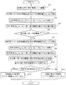
図15は、本実施形態1における雨滴検出処理の流れを示すフローチャートである。
画像解析ユニット102の光源制御部102Bは、信号処理部208からの画像信号の取得と連動しながら、光源部202の発光タイミングを制御し、まず、消灯時撮像フレームframe1,3(tb=1,2)と点灯時撮像フレームframe2,4(ta=1,2)とを撮像する(S1)。次に、画像解析ユニット102の検出処理部102Aは、点灯時撮像フレームframe2,4における雨滴検出用画像領域の各雨滴検出区分x内の合計輝度値y(x,ta=1),y(x,ta=2)を算出する(S2)。そして、各雨滴検出区分xについての点灯時差分ey(x,ta=2)=y(x,ta=2)−y(x,ta=1)を算出する(S3)。
FIG. 15 is a flowchart showing a flow of raindrop detection processing in the first embodiment.
The light source control unit 102B of the
点灯時差分ey(x,ta=2)の算出にあたり、画像解析ユニット102の検出処理部102Aは、まず、点灯時撮像フレームframe2(ta=1)の撮像画像データを撮像ユニット101から取得する。検出処理部102Aでは、この取得した撮像画像データから点灯時撮像フレームframe2の合計輝度値y(x,ta=1)を算出したら、記憶部102Dに一時的に記憶したり、その出力を遅延させたりする。その後、画像解析ユニット102の検出処理部102Aは、次の点灯時撮像フレームframe4の撮像画像データを撮像ユニット101から取得して合計輝度値y(x,ta=2)を算出したら、一時記憶され又は遅延された前回の合計輝度値y(x,ta=1)を用いて、点灯時差分ey(x,ta=2)を算出する。
In calculating the lighting difference e y (x, ta = 2), the
次に、検出処理部102Aは、このようにして算出した各雨滴検出区分xの点灯時差分ey(x,ta=2)がそれぞれ第一差分閾値Ey未満であるか否かを判断し、点灯時差分ey(x,ta=2)が第一差分閾値Ey未満である雨滴検出区分xの数を求める(S4)。このときの第一差分閾値Eyは、雨滴の付着あるいはワイパー107による雨滴の除去によって雨滴の付着量が変動したときの点灯時差分ey(x,ta=2)の変動量を検出できる適切な値に適宜設定される。なお、本実施形態1では、雨滴が付着すると合計輝度値が小さくなるので、雨滴が付着したときの点灯時差分ey(x,ta)=y(x,ta)−y(x,ta−1)は負の値をとるので、第一差分閾値Eyは負の値で適宜設定される。
Next, the
なお、ここでは、各雨滴検出区分x内の合計輝度値y(x,ta)の変化量(照明時変化量)を、今回の点灯時撮像フレームの合計輝度値y(x,ta)から、その直前の点灯時撮像フレームの合計輝度値y(x,ta−1)を差し引いた点灯時差分ey(x,ta)を用いているが、これに限られない。 Here, the amount of change (the amount of change during illumination) of the total luminance value y (x, ta) in each raindrop detection section x is calculated from the total luminance value y (x, ta) of the current lighting imaging frame. Although the lighting difference e y (x, ta) obtained by subtracting the total luminance value y (x, ta−1) of the lighting imaging frame immediately before that is used, it is not limited to this.
例えば、直前の点灯時撮像フレームの合計輝度値y(x,ta−1)から今回の点灯時撮像フレームの合計輝度値y(x,ta)を差し引いたものでもよい。この場合、本実施形態1のように雨滴が付着すると合計輝度値が小さくなるケースでは、雨滴が付着したときの点灯時差分ey(x,ta)=y(x,ta−1)−y(x,ta)は正の値をとるので、第一差分閾値Eyは正の値で適宜設定される。このとき、処理ステップS4では、各雨滴検出区分xの点灯時差分ey(x,ta)がそれぞれ第一差分閾値Ey以上である雨滴検出区分xの数を求めることになる。 For example, the total luminance value y (x, ta-1) of the immediately previous lighting imaging frame may be subtracted from the total luminance value y (x, ta) of the current lighting imaging frame. In this case, in the case where the total luminance value becomes small when raindrops are attached as in the first embodiment, the lighting difference e y (x, ta) = y (x, ta−1) −y when the raindrops are attached. Since (x, ta) takes a positive value, the first difference threshold Ey is appropriately set to a positive value. At this time, in processing step S4, the number of raindrop detection sections x in which the lighting difference e y (x, ta) of each raindrop detection section x is equal to or greater than the first difference threshold value Ey is obtained.
また、例えば、直前の点灯時撮像フレームの合計輝度値y(x,ta−1)と今回の点灯時撮像フレームの合計輝度値y(x,ta)との差分の絶対値であってもよい。この場合、本実施形態1のように雨滴が付着すると合計輝度値が小さくなるケースでは、雨滴が付着したときの点灯時差分ey(x,ta)=|y(x,ta)−y(x,ta−1)|は、正の値をとるので、第一差分閾値Eyは正の値で適宜設定される。このとき、処理ステップS4では、各雨滴検出区分xの点灯時差分ey(x,ta)がそれぞれ第一差分閾値Ey以上である雨滴検出区分xの数を求めることになる。 Further, for example, it may be an absolute value of a difference between the total luminance value y (x, ta-1) of the immediately previous lighting imaging frame and the total luminance value y (x, ta) of the current lighting imaging frame. . In this case, in the case where the total luminance value becomes small when raindrops adhere as in the first embodiment, the lighting difference e y (x, ta) = | y (x, ta) −y ( Since x, ta-1) | takes a positive value, the first difference threshold value Ey is appropriately set to a positive value. At this time, in processing step S4, the number of raindrop detection sections x in which the lighting difference e y (x, ta) of each raindrop detection section x is equal to or greater than the first difference threshold value Ey is obtained.
なお、各雨滴検出区分x内の合計輝度値y(x,ta)の変化量(照明時変化量)を観測する変化観測期間も適宜設定できるので、連続する2つの撮像フレーム間における差分に限らず、2つ以上の離れた撮像フレーム間における差分を用いてもよい。 Note that the change observation period for observing the change amount (change amount during illumination) of the total luminance value y (x, ta) in each raindrop detection section x can also be set as appropriate, so that it is limited to the difference between two consecutive imaging frames. Instead, a difference between two or more distant imaging frames may be used.
また、各雨滴検出区分x内の合計輝度値y(x,ta)の変化量(照明時変化量)は、例えば、時間的に近接する複数の合計輝度値の平均値や中央値などを用いて、時間方向に平滑化した値を利用してもよい。このように時間方向に平滑化することで、短時間に生じるパルス状のノイズを緩和したり、信号の時間的な揺らぎに起因して偶発的に照明時変化量が極端に大きくなるリスクを低減したりすることができる。 Further, as the amount of change (total amount of change during illumination) of the total luminance value y (x, ta) in each raindrop detection section x, for example, an average value or median value of a plurality of total luminance values that are close in time is used. Thus, a value smoothed in the time direction may be used. By smoothing in the time direction in this way, the pulse-like noise that occurs in a short time can be mitigated, and the risk of accidental changes in lighting due to temporal fluctuations in the signal is reduced. You can do it.
画像解析ユニット102の検出処理部102Aは、点灯時差分ey(x,ta=2)が第一差分閾値Ey未満である雨滴検出区分xの数を求めたら、求めた区分数が第一判定閾値F1を超えているか否かを判定する(S5)。この第一判定閾値F1も適宜設定することができる。求めた区分数が第一判定閾値F1以下である場合には(S5のNo)、雨滴は検出されなかったとして、雨滴不検出の処理結果が画像解析ユニット102からワイパー制御ユニット106へ出力される(S12)。これにより、ワイパー制御ユニット106は、ワイパー107の駆動を停止させるなどの制御を実施する。
When the
一方、求めた区分数が第一判定閾値F1を超えている場合(S5のYes)、雨滴の付着によって雨滴の付着量が増加したことにより点灯時差分ey(x,ta=2)が変動した可能性が高い。ただし、この点灯時差分ey(x,ta=2)の変動が、その点灯時差分ey(x,ta=2)を算出した変化観測期間(連続する2つの点灯時撮像フレームframe2,4を撮像するのに要する時間)内に外乱光の光量が変化したことによって生じた可能性や、ブラックレベル補正機能(BLC)による可能性もある。そこで、本実施形態1では、次に、第一差分閾値Ey未満であると判断された点灯時差分ey(x,ta=2)のなかに、外乱光変動成分やBLC変動成分が含まれているか否かを判定するための処理を実施する。 On the other hand, when the determined number of divisions exceeds the first determination threshold value F1 (Yes in S5), the lighting difference e y (x, ta = 2) varies due to an increase in the amount of raindrops attached due to raindrops. It is highly possible. However, the lighting time difference e y (x, ta = 2 ) variation of its lit difference e y (x, ta = 2 ) 2 single lit imaging frame calculated change observed period (successive frame2,4 There is a possibility that it is caused by a change in the amount of disturbance light within a period of time required for imaging the image or a black level correction function (BLC). Therefore, in the first embodiment, the disturbance light fluctuation component and the BLC fluctuation component are included in the lighting difference e y (x, ta = 2) determined to be less than the first difference threshold Ey. A process for determining whether or not the
具体的には、画像解析ユニット102の検出処理部102Aは、まず、消灯時撮像フレームframe1,3における雨滴検出用画像領域の各雨滴検出区分x内の輝度値総和d(x,tb=1),d(x,tb=2)を算出する(S6)。そして、各雨滴検出区分xについての消灯時差分ed(x,tb=2)=d(x,tb=2)−d(x,tb=1)を算出する(S7)。この消灯時差分ed(x,tb=2)の算出方法は、点灯時差分ey(x,ta=2)の算出方法と同様である。
Specifically, the
次に、検出処理部102Aは、このようにして算出した各雨滴検出区分xの消灯時差分ed(x,tb=2)がそれぞれ第二差分閾値Ed未満であるか否かを判断し、消灯時差分ed(x,tb=2)が第二差分閾値Ed未満である雨滴検出区分xの数を求める(S8)。ここで、雨滴変動成分として誤認され得る外乱光変動成分は消灯時差分ed(x,tb)=d(x,tb)−d(x,tb−1)が負の値をとる場合なので、第二差分閾値Edは負の値で適宜設定される。なお、第二差分閾値Ed未満であるか否かを判断については、上述した処理ステップS4において点灯時差分ey(x,ta=2)が第一差分閾値Ey未満であると判断した雨滴検出区分xのみを対象に行うようにしても良い。
Next, the
また、ここでは、各雨滴検出区分x内の輝度値総和d(x,tb)の変化量(非照明時変化量)を、今回の消灯時撮像フレームの輝度値総和d(x,tb)から、その直前の消灯時撮像フレームの輝度値総和d(x,tb−1)を差し引いた消灯時差分ed(x,tb)を用いているが、これに限られない。 Further, here, the amount of change (the amount of change during non-illumination) of the luminance value sum d (x, tb) in each raindrop detection section x is calculated from the luminance value sum d (x, tb) of the imaging frame when the light is turned off this time. Although the light-off time difference e d (x, tb) obtained by subtracting the luminance value sum d (x, tb−1) of the light-off imaging frame immediately before that is used, it is not limited to this.
例えば、直前の消灯時撮像フレームの輝度値総和d(x,tb−1)から今回の消灯時撮像フレームの輝度値総和d(x,tb)を差し引いたものでもよい。この場合、本実施形態1のように雨滴が付着すると合計輝度値が小さくなるケースにおいて雨滴変動成分として誤認され得る外乱光の光量減少時には、消灯時差分ed(x,tb)=d(x,tb−1)−d(x,tb)が正の値をとるので、第二差分閾値Edは正の値で適宜設定される。このとき、処理ステップS8では、各雨滴検出区分xの消灯時差分ed(x,tb)がそれぞれ第二差分閾値Ed以上である雨滴検出区分xの数を求めることになる。 For example, the sum of the luminance values d (x, tb) of the imaging frame when the light is turned off may be subtracted from the sum of luminance values d (x, tb-1) of the imaging frame when the light is turned off immediately before. In this case, when the amount of disturbance light that can be mistaken as a raindrop fluctuation component is reduced in the case where the total luminance value is reduced when raindrops are attached as in the first embodiment, the extinction difference e d (x, tb) = d (x , Tb−1) −d (x, tb) has a positive value, and therefore the second difference threshold Ed is appropriately set to a positive value. At this time, in the process step S8, so that the light-off difference e d (x, tb) of each raindrop detection segment x is determined the number of rain detection segment x is the second difference threshold Ed more.
また、例えば、直前の消灯時撮像フレームの輝度値総和d(x,tb−1)と今回の消灯時撮像フレームの輝度値総和d(x,tb)との差分の絶対値であってもよい。この場合、本実施形態1のように雨滴が付着すると合計輝度値が小さくなるケースにおいて雨滴変動成分として誤認され得る外乱光の光量減少時には、消灯時差分ed(x,tb)=|d(x,tb)−d(x,tb−1)|は、正の値をとるので、第二差分閾値Edは正の値で適宜設定される。このとき、処理ステップS8では、各雨滴検出区分xの消灯時差分ed(x,tb)がそれぞれ第二差分閾値Ed以上である雨滴検出区分xの数を求めることになる。 Further, for example, it may be an absolute value of a difference between the sum of luminance values d (x, tb-1) of the immediately previous imaging frame when the light is turned off and the total luminance value d (x, tb) of the current imaging frame when the light is turned off. . In this case, when the amount of disturbance light that can be mistaken as a raindrop fluctuation component is reduced in the case where the total luminance value is reduced when raindrops are attached as in the first embodiment, the extinction difference e d (x, tb) = | d ( x, tb) −d (x, tb−1) | takes a positive value, and therefore the second difference threshold Ed is appropriately set to a positive value. At this time, in the process step S8, so that the light-off difference e d (x, tb) of each raindrop detection segment x is determined the number of rain detection segment x is the second difference threshold Ed more.
なお、各雨滴検出区分x内の輝度値総和d(x,tb)の変化量(非照明時変化量)を算出する期間も適宜設定できるので、連続する2つの撮像フレーム間における差分に限らず、2つ以上の離れた撮像フレーム間における差分を用いてもよい。 Note that the period for calculating the amount of change (total amount of change during non-illumination) of the luminance value sum d (x, tb) within each raindrop detection section x can also be set as appropriate, and thus is not limited to the difference between two consecutive imaging frames. Differences between two or more distant imaging frames may be used.
また、消灯時差分ed(x,tb)を算出する期間は、上述した点灯時差分ey(x,ta)を算出する変化観測期間と一致している必要はないが、この変化観測期間に近い期間に設定することが望ましい。例えば、点灯時差分ey(x,ta=2)に対応する消灯時差分として、例えば、ed(x,tb=3)−ed(x,tb=2)や、ed(x,tb=3)−ed(x,tb=1)などを用いてもよい。 Further, the period for calculating the turn-off difference e d (x, tb) does not need to coincide with the change observation period for calculating the turn-on difference e y (x, ta), but this change observation period. It is desirable to set the period close to. For example, the lighting time difference e y (x, ta = 2 ) as off difference component corresponding to, for example, e d (x, tb = 3) -e d (x, tb = 2) and, e d (x, tb = 3) -e d (x, tb = 1) may be used.
画像解析ユニット102の検出処理部102Aは、消灯時差分ed(x,tb=2)が第二差分閾値Ed未満である雨滴検出区分xの数を求めたら、求めた区分数が第二判定閾値F2を超えているか否かを判定し、その判定結果(消灯時判定結果Htb)を、画像解析ユニット102の記憶部102Dに一時的に記憶する(S9)。なお、この第二判定閾値F2も適宜設定することができる。
その後、画像解析ユニット102の検出処理部102Aは、記憶部102Dから、過去の消灯時判定結果Htb−2を読み出し(S10)、その消灯時判定結果Htb−2において、過去の処理ステップS8で求めた区分数(すなわち、消灯時差分ed(x,tb−2)<第二差分閾値Edを満たす区分数)が第二判定閾値F2以下であることを示している場合には(S11のNo)、上述した第一差分閾値Ey未満である点灯時差分ey(x,ta=2)は、外乱光の光量変化に起因したものではなく、また、ブラックレベル補正機能に起因したものでもなく、雨滴の付着によって雨滴の付着量が増加したことに起因したものであると判断する。よって、雨滴が検出されたものとして、雨滴検出の処理結果が画像解析ユニット102からワイパー制御ユニット106へ出力される(S13)。これにより、ワイパー制御ユニット106は、ワイパー107の駆動を開始するなどの制御を実施する。
Thereafter, the
一方、記憶部102Dから読み出した過去の消灯時判定結果Htb−2において、過去の処理ステップS8で求めた区分数が第二判定閾値F2を超えていることを示している場合には(S11のYes)、上述した第一差分閾値Ey未満である点灯時差分ey(x,ta=2)は、外乱光の光量変化に起因したもの又はブラックレベル補正機能に起因したものである可能性が高い。よって、雨滴は検出されなかったとして、雨滴不検出の処理結果が画像解析ユニット102からワイパー制御ユニット106へ出力される(S12)。これにより、ワイパー制御ユニット106は、ワイパー107の駆動を停止させるなどの制御を実施する。
On the other hand, when the past extinction determination result Htb-2 read from the storage unit 102D indicates that the number of classifications obtained in the past processing step S8 exceeds the second determination threshold F2 (in S11) Yes), the lighting difference e y (x, ta = 2) that is less than the first difference threshold Ey described above may be due to a change in the amount of disturbance light or a black level correction function. high. Therefore, assuming that no raindrop has been detected, the processing result of raindrop non-detection is output from the
ここで、本実施形態では、今回の処理ステップS8で求めた区分数が第二判定閾値F2を超えているか否かの判定結果を用いず、過去の処理ステップS8(ここでは2回前の処理ステップS8)で求めた区分数が第二判定閾値F2を超えているか否かの判定結果を用いている。これは、ブラックレベル補正機能によるBLC変動成分を適切に把握するためである。以下、詳しく説明する。 Here, in the present embodiment, the determination result whether or not the number of divisions obtained in the current processing step S8 exceeds the second determination threshold value F2 is not used, and the past processing step S8 (in this case, the processing two times before) The determination result of whether or not the number of divisions obtained in step S8) exceeds the second determination threshold value F2 is used. This is to properly grasp the BLC fluctuation component due to the black level correction function. This will be described in detail below.
図16は、点灯時に画像センサ206から出力される出力信号(雨滴検出用画像領域の輝度値)がブラックレベル補正機能により変動した例を示すグラフである。
逆行などの強い外乱光が画像センサ206に入力すると、ブラックレベル補正機能が発揮される。これにより、画像センサ206から出力される出力信号は、画像センサ206が実際に受光する受光量が一定であっても、ブラックレベル補正機能によるレベル補正後の目標値に向けて徐々に変化する。図16に示す例では、時刻t1にレベル補正が開始されて、画像センサ206の点灯時の出力信号はVon1から徐々に低下し、レベル補正が完了する時刻t3で目標値であるVon2となる。この例では、時刻t4までレベル補正が継続されるので、時刻t3から時刻t4までの間、点灯時の出力信号はVon2で一定となる。その後、時刻t4にレベル補正が終了すると、画像センサ206の点灯時の出力信号はVon2から徐々に上昇し、レベル補正の終了が完了する時刻t6で目標値であるVon1に戻る。
FIG. 16 is a graph showing an example in which the output signal (luminance value of the raindrop detection image area) output from the
When strong disturbance light such as retrograde is input to the
この例において、時刻t1から時刻t3までの間においては、点灯時の合計輝度値y(x,ta)が徐々に低下することになるため、例えば雨滴が付着していないのに、第一差分閾値Ey未満である点灯時差分ey(x,ta)の区分数が第一判定閾値F1を超えるという雨滴検出条件を満たし、雨滴が検出されたという雨滴検出の結果が誤ってワイパー制御ユニットへ出力されてしまうおそれがある。逆に、雨滴が付着したのに、第一差分閾値Ey未満である点灯時差分ey(x,ta)の区分数が第一判定閾値F1を超えるという雨滴検出条件を満たさず、雨滴が検出されていないという雨滴不検出の結果が誤ってワイパー制御ユニットへ出力されてしまうおそれがある。 In this example, since the total luminance value y (x, ta) at the time of lighting gradually decreases from the time t1 to the time t3, for example, the first difference even though no raindrops are attached. The result of raindrop detection that a raindrop detection condition that the number of sections of the lighting difference e y (x, ta) that is less than the threshold value Ey exceeds the first determination threshold value F1 satisfies the raindrop detection condition and a raindrop is detected is erroneously sent to the wiper control unit. There is a risk of output. On the contrary, the raindrop is detected because the raindrop detection condition does not satisfy the raindrop detection condition that the number of sections of the lighting difference e y (x, ta) that is less than the first difference threshold Ey exceeds the first determination threshold F1 even though the raindrop has adhered. There is a possibility that the result of raindrop non-detection not being output is erroneously output to the wiper control unit.
図17は、消灯時に画像センサ206から出力される出力信号(雨滴検出用画像領域の輝度値)がブラックレベル補正機能により変動した例を示すグラフである。
消灯時における画像センサ206の出力信号は、外乱光の入射等によって、わずかながらも出力値Voff1を持つ。図17に示す例も、図16の例と同じタイミングでブラックレベル補正機能によるレベル補正が行われている。そのため、時刻t1にレベル補正が開始されることで、消灯時における画像センサ206の出力信号はVoff1から徐々に低下する。ところが、消灯時における画像センサ206の出力信号はもともとの値が低いことから、点灯時における画像センサ206の出力信号についてのレベル補正が完了する時刻t3になる前の時刻t2の時点で底打ちしてゼロになり、その後は、ゼロで一定となる。一方、消灯時における画像センサ206の出力信号は、時刻t4にレベル補正が終了しても、すぐには上昇せず、時刻t4よりも後の時刻t5の時点になってゼロから上昇し始める。そして、レベル補正の終了が完了する時刻t6で目標値であるVoff1に戻る。
FIG. 17 is a graph illustrating an example in which the output signal (the luminance value of the raindrop detection image area) output from the
The output signal of the
仮に、ブラックレベル補正機能によるレベル補正による消灯時の出力信号の変動が点灯時の出力信号と同じ変動を示す場合、すなわち、消灯時の出力信号も、レベル補正が完了する時刻t3まで低下し続け、また、レベル補正の終了する時刻t4から上昇を開始すれば、当該消灯時の出力信号の変動から、当該消灯時の直前又は直後の点灯時の出力信号にもレベル補正による変動が生じていることを把握できる。よって、今回の処理ステップS8で求めた区分数が第二判定閾値F2を超えているか否かの判定結果から、今回の処理ステップS5の判定結果(すなわち、今回の点灯時差分ey(x,ta)の区分数が第一判定閾値F1を超えるという雨滴検出条件を満たすか否かの判定結果)がレベル補正の誤差を含んでいるかどうかを適切に把握することは可能である。 If the fluctuation of the output signal when the light is turned off due to the level correction by the black level correction function shows the same fluctuation as the output signal when the light is turned on, that is, the output signal when the light is turned off continues to decrease until time t3 when the level correction is completed. In addition, if the rise starts at time t4 when the level correction ends, fluctuations due to the level correction also occur in the output signal at the time of lighting immediately before or immediately after the light extinction from the fluctuation of the output signal at the time of the light extinction. I can understand that. Therefore, from the determination result of whether or not the number of categories obtained in the current processing step S8 exceeds the second determination threshold F2, the determination result of the current processing step S5 (that is, the current lighting difference e y (x, It is possible to appropriately grasp whether or not the determination result of whether or not the raindrop detection condition that the number of sections of ta) exceeds the first determination threshold F1 includes a level correction error.
しかしながら、図17に示すように、ブラックレベル補正機能によるレベル補正による消灯時の出力信号の変動は点灯時の出力信号と同じ変動を示さない。すなわち、消灯時の出力信号は、レベル補正が完了する時刻t3よりも前の時刻t2の時点でゼロになってしまい、その後はゼロのまま一定値をとる。そのため、時刻t2から時刻t3までの間は、雨滴が付着していないのに、レベル補正により点灯時の合計輝度値y(x,ta)については徐々に低下するので、第一差分閾値Ey未満である点灯時差分ey(x,ta)の区分数が第一判定閾値F1を超えるという雨滴検出条件を満たす一方(S5のYes)、消灯時の輝度値総和d(x,tb)についてはレベル補正中でもゼロで一定になっている。よって、第二差分閾値Ed未満である消灯時差分ed(x,tb)の区分数が第二判定閾値F2以下であるという消灯時判定結果Htbが出され、処理ステップS5の判断結果は、外乱光やレベル補正の影響を受けていないと判断される結果、雨滴が検出されたという雨滴検出の結果が誤ってワイパー制御ユニットへ出力されてしまう。 However, as shown in FIG. 17, the fluctuation of the output signal when the light is turned off due to the level correction by the black level correction function does not show the same fluctuation as the output signal when the light is turned on. That is, the output signal at the time of extinction becomes zero at the time t2 before the time t3 when the level correction is completed, and thereafter takes a constant value as zero. Therefore, from time t2 to time t3, no raindrops are attached, but the total luminance value y (x, ta) at the time of lighting is gradually decreased by level correction, so that it is less than the first difference threshold Ey. While the raindrop detection condition that the number of sections of the lighting difference e y (x, ta) that exceeds the first determination threshold F1 is satisfied (Yes in S5), the luminance value sum d (x, tb) when the lamp is turned off It remains constant at zero even during level correction. Therefore, the turn-off determination result Htb that the number of sections of the turn-off difference e d (x, tb) that is less than the second difference threshold Ed is equal to or less than the second determination threshold F2 is output, and the determination result of the processing step S5 is As a result of being determined not to be affected by disturbance light or level correction, a raindrop detection result indicating that a raindrop has been detected is erroneously output to the wiper control unit.
これに対し、本実施形態においては、処理ステップS5の判断結果が外乱光やブラックレベル補正機能によるレベル補正の影響を受けているか否かの判断は、過去(2回前)の処理ステップS6〜S8によって判定された消灯時判定結果Htb−2を読み出して(S10)、その消灯時判定結果Htb−2を用いて行う(S11)。これにより、時刻t2から時刻t3までの間における処理ステップS5の判断結果については、時刻t1から時刻t2までの間における消灯時の輝度値総和d(x,tb−2)、すなわち、レベル補正により徐々に低下している消灯時の輝度値総和d(x,tb−2)を用いることができる。その結果、この消灯時の輝度値総和d(x,tb−2)から算出される消灯時差分ed(x,tb−2)が第二差分閾値Ed未満である区分数が第二判定閾値F2を超えているという消灯時判定結果Htb−2が出されることになる。その結果、処理ステップS5の判断結果は、外乱光やレベル補正の影響を受けていると判断され、雨滴が検出されていないという雨滴不検出の結果が正しくワイパー制御ユニットへ出力される。 On the other hand, in the present embodiment, whether or not the determination result of the processing step S5 is affected by ambient light or level correction by the black level correction function is determined based on the previous (two times before) processing steps S6 to S6. The turn-off determination result Htb-2 determined in S8 is read (S10), and the turn-off determination result Htb-2 is used (S11). As a result, the determination result of processing step S5 between time t2 and time t3 is the luminance value sum d (x, tb-2) at the time of extinction between time t1 and time t2, that is, by level correction. The luminance value sum d (x, tb-2) at the time of extinguishing that gradually decreases can be used. As a result, the brightness sum d (x, tb-2) at the time of off is the number of segments off when the difference e d (x, tb-2 ) is less than the second difference threshold Ed calculated from the second determination threshold value The turn-off determination result Htb-2 that exceeds F2 is output. As a result, it is determined that the determination result of processing step S5 is affected by disturbance light or level correction, and the result of raindrop non-detection that no raindrop is detected is correctly output to the wiper control unit.
以上、本実施形態1よれば、ブラックレベル補正機能によるレベル補正の影響によって、実際には雨滴量が増加していないのに(雨が降っていないのに)、雨滴が検出されたという雨滴検出の結果が誤ってワイパー制御ユニットへ出力され、ワイパーが誤って動作してしまう事態を回避できる。 As described above, according to the first embodiment, the raindrop detection that the raindrop is detected even though the raindrop amount has not actually increased due to the influence of the level correction by the black level correction function (even though it is not raining). It is possible to avoid a situation in which the result of the above is erroneously output to the wiper control unit and the wiper operates erroneously.
なお、本実施形態1では、今回の点灯時の合計輝度値に基づく判断結果(S5)についてのレベル補正の影響を過去の消灯時判定結果Htb−2を用いて判断しているが、過去の点灯時の合計輝度値に基づく判断結果についてのレベル補正の影響を、今回の消灯時判定結果Htbを用いて判断してもよい。この場合、実際には雨滴量が減少していないのに、雨滴が検出されていないという雨滴不検出の結果が誤って出力されるような事態を回避できる。 In the first embodiment, the influence of the level correction on the determination result (S5) based on the total luminance value at the time of lighting this time is determined using the past determination result Htb-2 at the time of turning off. The influence of the level correction on the determination result based on the total brightness value at the time of lighting may be determined using the current determination result at turning off Htb. In this case, it is possible to avoid a situation in which a raindrop non-detection result that no raindrop is detected is erroneously output even though the raindrop amount has not actually decreased.
詳しくは、図16に示すように、時刻t4から時刻t5までの間は、雨滴量が減少していなくても、レベル補正によって点灯時の合計輝度値y(x,ta)が徐々に上昇する一方、消灯時の出力信号は、図17に示すように、時刻t4よりも後の時刻t5の時点まではゼロのまま一定であり、時刻t5になってゼロから上昇し始める。そのため、時刻t4から時刻t5までの間の点灯時の合計輝度値y(x,ta)についてのレベル補正の影響は、時刻t4から時刻t5までの間の消灯時の輝度値総和d(x,tb)を用いて判断することができない。このとき、過去の点灯時の合計輝度値に基づく判断結果についてのレベル補正の影響を、今回の消灯時判定結果Htbを用いて判断するようにすれば、時刻t4から時刻t5までの間の点灯時の合計輝度値y(x,ta−2)についてのレベル補正の影響を、時刻t5から時刻t6までの間の消灯時の輝度値総和d(x,tb)を用いて判断することが可能となる。時刻t5から時刻t6までの間の消灯時の輝度値総和d(x,tb)は、レベル補正により徐々に上昇するので、時刻t4から時刻t5までの間の点灯時の合計輝度値y(x,ta−2)についてのレベル補正の影響を適切に判断することができる。 Specifically, as shown in FIG. 16, from time t4 to time t5, even when the amount of raindrops does not decrease, the total luminance value y (x, ta) at the time of lighting gradually increases by level correction. On the other hand, as shown in FIG. 17, the output signal at the time of extinction remains constant at zero until time t5 after time t4, and starts to rise from zero at time t5. Therefore, the influence of level correction on the total luminance value y (x, ta) during lighting from time t4 to time t5 is the sum of luminance values d (x, ta during lighting) from time t4 to time t5. It cannot be determined using tb). At this time, if the influence of the level correction on the determination result based on the total luminance value at the time of lighting in the past is determined using the determination result Htb at the time of extinction at this time, the lighting from time t4 to time t5 is performed. The influence of level correction on the total luminance value y (x, ta-2) at the time can be determined using the total luminance value d (x, tb) when the light is extinguished between time t5 and time t6. It becomes. Since the luminance value sum d (x, tb) at the time of extinction from time t5 to time t6 gradually increases due to the level correction, the total luminance value y (x at lighting) from time t4 to time t5. , Ta-2) can be appropriately determined.
また、本実施形態では、点灯時の合計輝度値に基づく判断結果は今回の処理時のものを用いているが、過去の処理時のものを用いてもよい。この場合、点灯時の合計輝度値に基づく点灯時判定結果Htaと消灯時の輝度値総和に基づく消灯時判定結果Htbの両方とも一時的に記憶部102Dへ記憶しておき、後の処理時においては、点灯時判定結果Hta−1と消灯時の輝度値総和に基づく消灯時判定結果Htb−3を読み出して用いればよい。 In the present embodiment, the determination result based on the total luminance value at the time of lighting is used in the current processing, but the determination result in the past processing may be used. In this case, both the lighting determination result Hta based on the total luminance value during lighting and the lighting determination result Htb based on the sum of luminance values when extinguished are temporarily stored in the storage unit 102D, and in subsequent processing May be read out and used for the turn-on determination result Hta-1 and the turn-off determination result Htb-3 based on the sum of luminance values at turn-off.
また、本実施形態では、時刻t6直後の期間において、処理ステップS5の判断結果が外乱光やレベル補正の影響を受けているか否かの判断が、時刻t5から時刻t6までの間における消灯時の輝度値総和、すなわち、レベル補正により徐々に低下している消灯時の輝度値総和が用いられる。そのため、当該処理ステップS5の判断結果は、レベル補正の影響を受けていないものであるが、外乱光やレベル補正の影響を受けていると判断され、実際には雨滴量が増加している場合でも、雨滴が検出されていないという雨滴不検出の結果がワイパー制御ユニットへ出力されることになる。ただし、この場合でも、しばらくして時刻t6以降の消灯時の輝度値総和を用いて消灯時判定がなされることで、雨滴が検出されたという雨滴検出の結果がワイパー制御ユニットへ出力されることになる。すなわち、雨滴量が増加し始めてから少し遅れてワイパーが動作することにはなるだけで、実質的な弊害は少ない。 In the present embodiment, in the period immediately after time t6, whether or not the determination result of processing step S5 is affected by ambient light or level correction is determined when the light is turned off between time t5 and time t6. The sum of the brightness values, that is, the sum of the brightness values at the time of extinguishing which is gradually decreased by the level correction is used. For this reason, the determination result of the processing step S5 is not affected by the level correction, but is determined to be affected by the ambient light or the level correction, and the raindrop amount actually increases. However, the result of no raindrop detection that no raindrop has been detected is output to the wiper control unit. However, even in this case, the result of the raindrop detection that the raindrop has been detected is output to the wiper control unit by making a judgment at the time of turn-off using the sum of luminance values at the time of turn-off after time t6 after a while. become. That is, the wiper operates only a little after the raindrop amount starts to increase, and there are few substantial adverse effects.
また、本実施形態では、画像センサ206のブラックレベル補正機能によるレベル補正に起因した誤検出又は検出漏れを抑制する例について説明したが、画像センサ206の自動露光補正機能などの他の原因によって、消灯時の輝度値総和は一定なのに点灯時の合計輝度値に変動が生じ、これにより誤検出又は検出漏れが生じ得る場合には、そのような誤検出又は検出漏れも同様に抑制することが可能である。したがって、画像のダイナミックレンジを有効活用するために行われる明度補正やコントラスト補正などによるレベル補正であっても同様である。
Further, in the present embodiment, an example of suppressing erroneous detection or detection omission due to level correction by the black level correction function of the
以上は、点灯時撮像フレームframe4(ta=2)の撮像完了後に実施される雨滴検出処理であるが、この雨滴検出処理が完了したら、次に、点灯時撮像フレームframe6(ta=3)の撮像完了後に同様の雨滴検出処理が繰り返し実施される。なお、このときの点灯時差分はey(x,ta=3)=y(x,ta=3)−y(x,ta=2)であり、消灯時差分はed(x,tb=3)=d(x,tb=3)−d(x,tb=2)である。このようにして、雨滴検出処理は、雨滴の付着を検出する機能が有効になっている間は、繰り返し実施される。ただし、雨滴検出処理の実施タイミングは、任意に設定でき、点灯時撮像フレームframe6(ta=3)の撮像完了後に、毎回、雨滴検出処理を実施するのではなく、例えば、点灯時撮像フレームframe6(ta=3)の撮像が2回以上の行われるたびに雨滴検出処理を実施するようにしてもよい。 The above is the raindrop detection process performed after completion of imaging of the lighting imaging frame frame4 (ta = 2). When this raindrop detection processing is completed, the imaging of the lighting imaging frame frame6 (ta = 3) is performed next. The same raindrop detection process is repeatedly performed after completion. Note that the lighting difference at this time is e y (x, ta = 3) = y (x, ta = 3) −y (x, ta = 2), and the lighting difference is e d (x, tb = 3) = d (x, tb = 3) −d (x, tb = 2). In this manner, the raindrop detection process is repeatedly performed while the function of detecting the attachment of raindrops is enabled. However, the execution timing of the raindrop detection process can be arbitrarily set, and the raindrop detection process is not performed every time after completion of the imaging of the lighting imaging frame frame6 (ta = 3), for example, the lighting imaging frame frame6 ( The raindrop detection process may be performed every time the imaging of ta = 3) is performed twice or more.
また、本実施形態1において、雨滴の検出条件として、点灯時差分ey(x,ta)が第一差分閾値Ey未満である雨滴検出区分xの数が第一判定閾値F1を超えているという条件を含んでいるが、雨滴の検出条件には、この条件に代えて又はこの条件に加えて、他の条件を採用してもよい。例えば、全雨滴検出区分xの点灯時差分ey(x,ta)の平均値や分散値を導出し、その導出値が所定の閾値を上回る又は下回るという条件を採用してもよい。この条件は、局所的に生じるノイズに対する耐性を高めることができる点で有効である。 Further, in the first embodiment, as a raindrop detection condition, the number of raindrop detection sections x in which the lighting difference e y (x, ta) is less than the first difference threshold Ey exceeds the first determination threshold F1. Although conditions are included, other conditions may be adopted as raindrop detection conditions instead of or in addition to this condition. For example, a condition may be adopted in which an average value or a variance value of the lighting difference e y (x, ta) of the all raindrop detection section x is derived and the derived value exceeds or falls below a predetermined threshold value. This condition is effective in that the resistance to locally generated noise can be increased.
また、各雨滴検出区分x内の合計輝度値y(x,ta)の変化量(照明時変化量)として、各雨滴検出区分x内の今回の合計輝度値y(x,ta)と直前の合計輝度値y(x,ta−1)との差分である点灯時差分ey(x,ta)とは別のパラメータを用いた条件を採用してもよい。
例えば、各雨滴検出区分x内における個々の画素について今回の画素値と直前の画素値間の画素別差分値を導出し、その画素別差分値が所定の閾値を上回る又は下回る画素の個数を、点灯時差分ey(x,ta)に代わるパラメータとして用いてもよい。この場合、各雨滴検出区分x内において局所的に雨滴が付着した場合でも、雨滴を適切に検出することが可能となる点で有効である。
Further, as the amount of change in the total luminance value y (x, ta) in each raindrop detection section x (the amount of change during illumination), the current total luminance value y (x, ta) in each raindrop detection section x and the immediately preceding A condition using a parameter different from the lighting difference e y (x, ta) that is a difference from the total luminance value y (x, ta-1) may be adopted.
For example, for each pixel in each raindrop detection section x, a pixel-specific difference value between the current pixel value and the previous pixel value is derived, and the number of pixels for which the pixel-specific difference value exceeds or falls below a predetermined threshold is calculated as follows: It may be used as a parameter instead of the lighting difference e y (x, ta). In this case, it is effective in that raindrops can be appropriately detected even when raindrops locally adhere within each raindrop detection section x.
また、例えば、各雨滴検出区分x内における画素別差分値の平均値や分散値を導出し、その導出値が所定の閾値を上回る又は下回るという条件を採用してもよい。この条件は、各雨滴検出区分x内において局所的に生じるノイズに対する耐性を高めることができる点で有効である。ただし、画素別差分値は、局所的に正負が逆転した結果が得られる場合があり、単に画素別差分値の平均値等から雨滴検出条件を判断すると、雨滴変動成分が不当に小さく評価されるおそれがある。したがって、例えば、各雨滴検出区分x内における画素別差分値の絶対値の合計が所定の閾値を上回るという条件を採用してもよい。 In addition, for example, a condition may be employed in which an average value or a variance value of pixel-specific difference values in each raindrop detection section x is derived, and the derived value exceeds or falls below a predetermined threshold. This condition is effective in that it is possible to enhance resistance to noise that occurs locally in each raindrop detection section x. However, the difference value for each pixel may obtain a result in which the sign is reversed locally. If the raindrop detection condition is simply determined from the average value of the difference value for each pixel, the raindrop fluctuation component is evaluated to be unduly small. There is a fear. Therefore, for example, a condition that the sum of absolute values of pixel-specific difference values in each raindrop detection section x exceeds a predetermined threshold value may be adopted.
なお、雨滴は、空間的なばらつきをもって付着することから、各雨滴検出区分x内における画素別差分値も同様に空間的なばらつきが生じる。よって、各雨滴検出区分x内における画素別差分値の分散値からも、雨滴検出条件を判断することができる。また、後述する実施形態2のように、雨滴によって光源光が屈折されたり反射されたりする場合、光源光が画像センサ206上に局所的に集光され、各雨滴検出区分x内における画素別差分値が局所的に上昇する場合がある。これを雨滴検出条件に反映させてもよい。
Since raindrops adhere with spatial variations, the pixel-specific difference values in each raindrop detection section x also have spatial variations. Therefore, the raindrop detection condition can also be determined from the variance value of the difference value for each pixel in each raindrop detection section x. In addition, when the light source light is refracted or reflected by raindrops as in the second embodiment to be described later, the light source light is locally focused on the
また、本実施形態1では、雨滴が検出されたか否かの判断を行う例であるが、点灯時差分ey(x,ta)に基づいて単位時間当たりに付着する雨滴量を推定し、推定した雨滴量を雨滴検出の結果として出力してもよい。この場合、例えば、ワイパー制御ユニット106は、画像解析ユニット102から取得した雨滴量に応じてワイパー107の動作速度(Low, High, Intervalなどの動作モード)を選択する制御を実行することが可能となる。
Further, the first embodiment is an example in which it is determined whether or not raindrops are detected, but the amount of raindrops attached per unit time is estimated based on the lighting difference e y (x, ta), and estimated. The amount of raindrops may be output as a result of raindrop detection. In this case, for example, the
〔変形例1〕
次に、本実施形態1の一変形例(以下、本変形例を「変形例1」という。)について説明する。
上述した実施形態1では、点灯時における各雨滴検出区分xの合計輝度値y(x,ta)の変化量(照明時変化量)である点灯時差分ey(x,ta)が雨滴検出条件を満たすか否かを判断しているが(S3〜S5)、本変形例1では、このような点灯時差分ey(x,ta)を算出せず、点灯時における各雨滴検出区分xの合計輝度値y(x,ta)が雨滴検出条件を満たすか否かを判断する。
[Modification 1]
Next, a modified example of the first embodiment (hereinafter referred to as “modified example 1”) will be described.
In the first embodiment described above, the lighting difference e y (x, ta) that is the amount of change (the amount of change during illumination) of the total luminance value y (x, ta) of each raindrop detection category x during lighting is the raindrop detection condition. However, in the first modification, such a lighting difference e y (x, ta) is not calculated, and each raindrop detection classification x at the time of lighting is not calculated. It is determined whether or not the total luminance value y (x, ta) satisfies the raindrop detection condition.
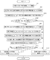
図18は、本変形例1における雨滴検出処理の流れを示すフローチャートである。
画像解析ユニット102の検出処理部102Aは、雨滴検出用画像領域の各雨滴検出区分x内の合計輝度値y(x,ta=1)を算出したら(S1,S2)、算出した各雨滴検出区分xの合計輝度値y(x,ta=1)がそれぞれ第三差分閾値Ey’未満であるか否かを判断し、合計輝度値y(x,ta=1)が第三差分閾値Ey’未満である雨滴検出区分xの数を求める(S31)。上述したとおり、合計輝度値y(x,ta)の値は雨滴の付着量が増えるほど小さくなることを考慮して、第三差分閾値Ey’は、雨滴が所定量以上付着したことを検出できる適切な値に適宜設定される。
FIG. 18 is a flowchart showing a flow of raindrop detection processing in the first modification.
When the
画像解析ユニット102の検出処理部102Aは、合計輝度値y(x,ta=1)が第三差分閾値Ey’未満である雨滴検出区分xの数を求めたら、求めた区分数が第三判定閾値F1’を超えているか否かを判定する(S32)。この第三判定閾値F1’も適宜設定することができる。求めた区分数が第三判定閾値F1’以下である場合には(S32のNo)、雨滴は検出されなかったとして、雨滴不検出の処理結果が画像解析ユニット102からワイパー制御ユニット106へ出力される(S12)。これにより、ワイパー制御ユニット106は、ワイパー107の駆動を停止させるなどの制御を実施する。
When the
一方、求めた区分数が第三判定閾値F1’を超えている場合(S32のYes)、雨滴が所定量以上付着したことにより合計輝度値y(x,ta=1)が第三差分閾値Ey’未満の値をとった可能性が高い。ただし、この合計輝度値y(x,ta=1)の値が、外乱光による可能性又はブラックレベル補正機能(BLC)による可能性もある。そこで、本変形例1でも、上述した実施形態1と同様に、第三差分閾値Ey’未満であると判断された合計輝度値y(x,ta=1)に、外乱光成分やBLC成分が含まれているか否かを判定するための処理を実施する。 On the other hand, when the determined number of divisions exceeds the third determination threshold value F1 ′ (Yes in S32), the total luminance value y (x, ta = 1) becomes the third difference threshold value Ey because a predetermined amount or more of raindrops have adhered. It is likely that a value less than 'is taken. However, the value of the total luminance value y (x, ta = 1) may be due to ambient light or the black level correction function (BLC). Therefore, also in the first modification, the disturbance light component and the BLC component are included in the total luminance value y (x, ta = 1) determined to be less than the third difference threshold Ey ′, as in the first embodiment. A process for determining whether or not it is included is performed.
具体的には、画像解析ユニット102の検出処理部102Aは、まず、雨滴検出用画像領域の各雨滴検出区分x内の輝度値総和d(x,tb=0),d(x,tb=1)を算出し(S6)、各雨滴検出区分xについての消灯時差分ed(x,tb=1)=d(x,tb=1)−d(x,tb=0)を算出する(S7)。そして、算出した各雨滴検出区分xの消灯時差分ed(x,tb=1)がそれぞれ第二差分閾値Ed未満であるか否かを判断し、消灯時差分ed(x,tb=1)が第二差分閾値Ed未満である雨滴検出区分xの数を求める(S8)。
Specifically, the
画像解析ユニット102の検出処理部102Aは、消灯時差分ed(x,tb=1)が第二差分閾値Ed未満である雨滴検出区分xの数を求めたら、求めた区分数が第二判定閾値F2を超えているか否かを判定し、その判定結果(消灯時判定結果Htb)を、画像解析ユニット102の記憶部102Dに一時的に記憶する(S9)。その後、画像解析ユニット102の検出処理部102Aは、記憶部102Dから、過去の消灯時判定結果Htb−2を読み出し(S10)、その消灯時判定結果Htb−2において、過去の処理ステップS8で求めた区分数(すなわち、消灯時差分ed(x,tb−2)<第二差分閾値Edを満たす区分数)が第二判定閾値F2以下であることを示している場合には(S11のNo)、上述した第三差分閾値Ey’未満である合計輝度値y(x,ta=1)は、外乱光やブラックレベル補正機能の影響を受けておらず、雨滴が所定量以上付着したことに起因したものであると判断する。よって、雨滴が検出されたものとして、雨滴検出の処理結果が画像解析ユニット102からワイパー制御ユニット106へ出力される(S13)。これにより、ワイパー制御ユニット106は、ワイパー107の駆動を開始するなどの制御を実施する。
一方、記憶部102Dから読み出した過去の消灯時判定結果Htb−2において、過去の処理ステップS8で求めた区分数が第二判定閾値F2を超えていることを示している場合には(S11のYes)、上述した第三差分閾値Ey’未満である合計輝度値y(x,ta=1)は、外乱光やブラックレベル補正機能に起因したものである可能性が高い。よって、雨滴は検出されなかったとして、雨滴不検出の処理結果が画像解析ユニット102からワイパー制御ユニット106へ出力される(S12)。これにより、ワイパー制御ユニット106は、ワイパー107の駆動を停止させるなどの制御を実施する。
On the other hand, when the past extinction determination result Htb-2 read from the storage unit 102D indicates that the number of classifications obtained in the past processing step S8 exceeds the second determination threshold F2 (in S11) Yes), the total luminance value y (x, ta = 1) that is less than the third difference threshold Ey ′ described above is highly likely to be caused by ambient light or the black level correction function. Therefore, assuming that no raindrop has been detected, the processing result of raindrop non-detection is output from the
なお、本変形例1において、今回の処理ステップS8で求めた区分数が第二判定閾値F2を超えているか否かの判定結果を用いず、過去の処理ステップS8(ここでは2回前の処理ステップS8)で求めた区分数が第二判定閾値F2を超えているか否かの判定結果を用いている理由は、上述した実施形態1と同様である。 In the first modification, the determination result whether or not the number of divisions obtained in the current processing step S8 exceeds the second determination threshold value F2 is not used, and the past processing step S8 (in this case, the processing two times before) The reason for using the determination result as to whether or not the number of divisions obtained in step S8) exceeds the second determination threshold value F2 is the same as in the first embodiment.
本変形例1によれば、各雨滴検出区分x内の合計輝度値y(x,ta)の変化量(照明時変化量)を算出する必要がないことから、処理ステップを簡略化できるというメリットがある。ただし、点灯時における各雨滴検出区分xの合計輝度値y(x,ta)を変動させる成分として、上述したように、レンズ、ミラー、プリズム等の光学部材の光学特性や光源の発光量などが温度変化によって変動して雨滴検出用画像領域の輝度値を変動させる温度変動成分や、これらの光学部材の光学特性や光源の発光量などが経時劣化によって変動して雨滴検出用画像領域の輝度値を変動させる経時劣化変動成分なども存在する。上述した実施形態1のように、点灯時差分ey(x,ta)を算出し、これを用いて雨滴検出条件を判断すれば、これらの温度変動成分や経時劣化変動成分の影響を除外できるが、本変形例1では、これらの温度変動成分や経時劣化変動成分の影響を受けることになるため、これらの温度変動成分や経時劣化変動成分の影響が大きいシステムにおいては、上述した実施形態1の方が高精度な雨滴検出が可能である。
According to the first modification, it is not necessary to calculate the amount of change (the amount of change during illumination) of the total luminance value y (x, ta) in each raindrop detection section x, so that the processing step can be simplified. There is. However, as described above, the components that change the total luminance value y (x, ta) of each raindrop detection section x at the time of lighting include the optical characteristics of optical members such as lenses, mirrors, and prisms, and the light emission amount of the light source. The temperature fluctuation component that fluctuates the brightness value of the raindrop detection image area due to temperature changes, the optical characteristics of these optical members, the light emission amount of the light source, etc. fluctuate due to deterioration over time, and the brightness value of the raindrop detection image area There is also a time-dependent deterioration fluctuation component that fluctuates. If the lighting difference e y (x, ta) is calculated and the raindrop detection condition is determined using the lighting difference e y (x, ta) as in
〔実施形態2〕
次に、本発明に係る物体検出装置を、上述した実施形態1と同様、車載機器制御システムに用いられる付着物検出装置に適用した他の実施形態(以下、本実施形態を「実施形態2」という。)について説明する。
上述した実施形態1においては、反射偏向プリズム230を用い、雨滴の付着箇所では照明光がフロントガラス外壁面を透過し、雨滴の非付着箇所では照明光がフロントガラス外壁面で反射して画像センサ206に受光される構成であった。これに対し、本実施形態2は、雨滴の非付着箇所では照明光がフロントガラス外壁面を透過し、雨滴の付着箇所ではフロントガラス外壁面を透過した照明光が雨滴で反射して画像センサ206に受光される構成である。具体的には、図19に示すような構成である。
[Embodiment 2]
Next, another embodiment (hereinafter, this embodiment is referred to as “
In the first embodiment described above, the
なお、図19の例では、光源部202から出射した照明光が直接フロントガラス105の内壁面に入射する構成となっているが、ミラー等の光路変更部材を介する構成としてもよい。この場合、上述した実施形態1と同様に、センサ基板207上に光源装置としての光源部202を実装することが可能となる。
In the example of FIG. 19, the illumination light emitted from the
図19中の光線Aは、光源部202から出射してフロントガラス105を通過する光線である。フロントガラス105の外壁面に雨滴203が付着していない場合、光源部202からフロントガラス105に向けて照射された光は、光線Aのように、フロントガラス105を透過してそのまま自車両100の外部に漏れ出る。
A light ray A in FIG. 19 is a light ray emitted from the
図19中の光線Bは、光源部202からの出射光がフロントガラス105の内壁面で正反射して撮像部200へ入射する光線である。光源部202からフロントガラス105へ向かう光の一部はフロントガラス105の内壁面で正反射する。この正反射光(光線B)の偏光成分は、一般に、その入射面に対して直交する方向(図19の紙面に対して垂直な方向)に振動するS偏光成分(水平偏光成分S)が支配的であることが知られている。光源部202から照射されてフロントガラス105の内壁面で正反射した正反射光(光線B)は、フロントガラス105の外壁面に付着する雨滴203の有無によって変動しないので、雨滴検出に不要な光であるばかりか、雨滴検出の検出精度を低下させる外乱光となる。本実施形態2では、この光線B(水平偏光成分S)をカットする偏光フィルタ層を光学フィルタ205に設け、この光線Bによって雨滴検出精度が低下することを抑制している。
A light beam B in FIG. 19 is a light beam that is emitted from the
図19中の光線Cは、光源部202からの出射光がフロントガラス105の内壁面を透過し、その後、フロントガラス105の外壁面に付着する雨滴で反射して撮像部200へ入射する光線である。光源部202からフロントガラス105へ向かう光の一部はフロントガラス105の内壁面を透過するが、その透過光は水平偏光成分Sよりも鉛直偏光成分Pの方が多い。そして、フロントガラス105の外壁面上に雨滴203が付着している場合、フロントガラス105の内壁面を透過した光は、前記光線Aのように外部へ漏れ出ずに、雨滴内部で多重反射して撮像部200側に向けて再度フロントガラス105内を透過し、撮像部200に入射する。このとき、撮像部200の光学フィルタ205における前段フィルタ210の赤外光透過フィルタ領域212は、光源部202の発光波長(赤外光)を透過させるように構成されているので、光線Cは赤外光透過フィルタ領域212を通過する。また、上述した光線B(水平偏光成分S)をカットする偏光フィルタ層は、鉛直偏光成分Pを透過するようにワイヤーグリッド構造の金属ワイヤーの長手方向が形成されているため、光線Cは当該偏光フィルタ層も透過する。よって、光線Cは、画像センサ206に到達し、その受光量によって雨滴の検出が行われる。
A light ray C in FIG. 19 is a light ray that is emitted from the
図19中の光線Dは、フロントガラス105の外部からフロントガラス105を透過して撮像部200に向かって入射してくる光線である。この光線Dも雨滴検出時の外乱光となり得るが、本実施形態2では、その光線Dの大部分が、光学フィルタ205における前段フィルタ210の赤外光透過フィルタ領域212によってカットされる。よって、この光線Dによって雨滴検出精度が低下することも抑制できる。
A light ray D in FIG. 19 is a light ray that passes through the
図19中の光線Eは、フロントガラス105の外部からフロントガラス105を透過して撮像部200に向かって入射してくる光線である。この光線Eは、光学フィルタ205における前段フィルタ210の赤外光カットフィルタ領域211によって赤外光帯域がカットされ、可視域の光のみが撮像される。この撮像画像は、対向車両のヘッドランプ及び先行車両のテールランプ並びに白線の検出などに利用される。
A light ray E in FIG. 19 is a light ray that passes through the
本実施形態2においては、雨滴によって屈折されたり反射されたりした光源光が画像センサ206に入射するため、撮像画像データの雨滴検出用画像領域214は、フロントガラス105の外壁面に雨滴が付着していない非付着箇所は低輝度な画像部分(低い画素値)となる一方、雨滴が付着している付着箇所は高輝度な画像部分(高い画素値)となる点で、上述した実施形態1とは異なるが、このような違いを考慮して各種閾値等を設定することで、上述した実施形態1と同様の処理を実現できる。
In the second embodiment, since light source light refracted or reflected by raindrops is incident on the
図20は、本実施形態2における雨滴検出処理の流れを示すフローチャートである。
なお、以下の説明では、上述した実施形態1と同様の部分についての説明は省略し、上述した実施形態1とは異なる部分を中心に説明する。
画像解析ユニット102の検出処理部102Aは、まず、各雨滴検出区分xについての点灯時差分ey(x,ta=2)を算出する(S1〜S3)。そして、算出した各雨滴検出区分xの点灯時差分ey(x,ta=2)がそれぞれ第一差分閾値Ey未満であるか否かを判断し、点灯時差分ey(x,ta=2)が第一差分閾値Ey未満である雨滴検出区分xの数を求める(S4)。
FIG. 20 is a flowchart showing a flow of raindrop detection processing according to the second embodiment.
In the following description, the description of the same parts as those in the first embodiment will be omitted, and the description will focus on parts different from those in the first embodiment.
First, the
ただし、本実施形態2のように雨滴が付着すると合計輝度値が大きくなるケースでは、雨滴が付着したときの点灯時差分ey(x,ta)=y(x,ta)−y(x,ta−1)は正の値をとるので、第一差分閾値Eyは正の値で適宜設定される。このとき、処理ステップS4では、各雨滴検出区分xの点灯時差分ey(x,ta)がそれぞれ第一差分閾値Ey以上である雨滴検出区分xの数を求めることになる。 However, in the case where the total luminance value increases when raindrops adhere as in the second embodiment, the lighting difference e y (x, ta) = y (x, ta) −y (x, Since ta-1) takes a positive value, the first difference threshold Ey is appropriately set to a positive value. At this time, in processing step S4, the number of raindrop detection sections x in which the lighting difference e y (x, ta) of each raindrop detection section x is equal to or greater than the first difference threshold value Ey is obtained.
また、例えば、各雨滴検出区分x内の合計輝度値y(x,ta)の変化量(照明時変化量)として、例えば、直前の点灯時撮像フレームの合計輝度値y(x,ta−1)から今回の点灯時撮像フレームの合計輝度値y(x,ta)を差し引いたものを用いる場合、本実施形態2のように雨滴が付着すると合計輝度値が大きくなるケースでは、雨滴が付着したときの点灯時差分ey(x,ta)=y(x,ta−1)−y(x,ta)は負の値をとるので、第一差分閾値Eyは負の値で適宜設定される。このとき、処理ステップS4では、各雨滴検出区分xの点灯時差分ey(x,ta)がそれぞれ第一差分閾値Ey未満である雨滴検出区分xの数を求めることになる。 Further, for example, as the amount of change (total amount of change during illumination) of the total luminance value y (x, ta) in each raindrop detection section x, for example, the total luminance value y (x, ta−1) of the immediately previous lighting imaging frame. ) Is subtracted from the total luminance value y (x, ta) of the lighting imaging frame at this time, in the case where the total luminance value becomes large when the raindrop is attached as in the second embodiment, the raindrop is attached. The lighting difference e y (x, ta) = y (x, ta−1) −y (x, ta) takes a negative value, so that the first difference threshold Ey is appropriately set to a negative value. . At this time, in the processing step S4, the number of raindrop detection sections x whose lighting difference e y (x, ta) of each raindrop detection section x is less than the first difference threshold value Ey is obtained.
また、例えば、各雨滴検出区分x内の合計輝度値y(x,ta)の変化量(照明時変化量)として、直前の点灯時撮像フレームの合計輝度値y(x,ta−1)と今回の点灯時撮像フレームの合計輝度値y(x,ta)との差分の絶対値を用いる場合、本実施形態2のように雨滴が付着すると合計輝度値が大きくなるケースでも、雨滴が付着したときの点灯時差分ey(x,ta)=|y(x,ta)−y(x,ta−1)|は、正の値をとるので、第一差分閾値Eyは正の値で適宜設定される。このとき、処理ステップS4では、各雨滴検出区分xの点灯時差分ey(x,ta)がそれぞれ第一差分閾値Ey以上である雨滴検出区分xの数を求めることになる。 Further, for example, as the amount of change (total amount of change during illumination) of the total luminance value y (x, ta) in each raindrop detection section x, the total luminance value y (x, ta-1) of the immediately previous lighting imaging frame When using the absolute value of the difference from the total luminance value y (x, ta) of the imaging frame at the time of lighting this time, even when raindrops are attached as in the second embodiment, raindrops are attached. Since the lighting difference e y (x, ta) = | y (x, ta) −y (x, ta−1) | takes a positive value, the first difference threshold Ey is a positive value as appropriate. Is set. At this time, in processing step S4, the number of raindrop detection sections x in which the lighting difference e y (x, ta) of each raindrop detection section x is equal to or greater than the first difference threshold value Ey is obtained.
画像解析ユニット102の検出処理部102Aは、点灯時差分ey(x,ta=2)が第一差分閾値Ey未満である雨滴検出区分xの数を求めたら、求めた区分数が第一判定閾値F1を超えているか否かを判定し、その判定結果(点灯時判定結果Hta)を、画像解析ユニット102の記憶部102Dに一時的に記憶する(S21)。
When the
その後、画像解析ユニット102の検出処理部102Aは、記憶部102Dから、過去の点灯時判定結果Hta−2を読み出し(S22)、その点灯時判定結果Hta−2において、過去の処理ステップS4で求めた区分数(すなわち、点灯時差分ey(x,ta−2)が第一差分閾値Ey未満である区分数)が第三判定閾値F1’以下であることを示している場合には(S23のNo)、雨滴は検出されなかったとして、雨滴不検出の処理結果が画像解析ユニット102からワイパー制御ユニット106へ出力される(S12)。これにより、ワイパー制御ユニット106は、ワイパー107の駆動を停止させるなどの制御を実施する。
Thereafter, the
一方、記憶部102Dから読み出した過去の点灯時判定結果Hta−2において、過去の処理ステップS4で求めた区分数が第三判定閾値F1’を超えていることを示している場合には(S23のYes)、雨滴の付着によって雨滴の付着量が増加したことにより点灯時差分ey(x,ta−2)が変動した可能性が高い。ただし、この点灯時差分ey(x,ta−2)の変動が、外乱光やブラックレベル補正機能(BLC)のレベル補正に起因したものである可能性もある。そこで、本実施形態2では、次に、当該点灯時差分ey(x,ta−2)のなかに、外乱光変動成分やBLC変動成分が含まれているか否かを判定するための処理を実施する。 On the other hand, when the past lighting determination result Hta-2 read from the storage unit 102D indicates that the number of categories obtained in the past processing step S4 exceeds the third determination threshold F1 ′ (S23). Yes), there is a high possibility that the lighting difference e y (x, ta−2) has fluctuated due to an increase in the amount of raindrops attached due to the attachment of raindrops. However, the fluctuation of the lighting difference e y (x, ta−2) may be caused by ambient light or level correction of the black level correction function (BLC). Therefore, in the second embodiment, next, a process for determining whether or not the disturbance light fluctuation component and the BLC fluctuation component are included in the lighting difference e y (x, ta−2). carry out.
具体的には、画像解析ユニット102の検出処理部102Aは、まず、消灯時撮像フレームframe1,3における雨滴検出用画像領域の各雨滴検出区分x内の輝度値総和d(x,tb=1),d(x,tb=2)を算出する(S6)。そして、各雨滴検出区分xについての消灯時差分ed(x,tb=2)=d(x,tb=2)−d(x,tb=1)を算出する(S7)。そして、検出処理部102Aは、算出した各雨滴検出区分xの消灯時差分ed(x,tb=2)がそれぞれ第二差分閾値Ed以上であるか否かを判断し、消灯時差分ed(x,tb=2)が第二差分閾値Ed未満である雨滴検出区分xの数を求める(S8)。
Specifically, the
本実施形態2のように雨滴が付着すると合計輝度値が大きくなるケースでは、雨滴変動成分として誤認され得る外乱光変動成分やBLC変動成分は、光量が増加する場合である。この場合、各雨滴検出区分x内の輝度値総和d(x,tb)の変化量(非照明時変化量)として、消灯時差分ed(x,tb)=d(x,tb)−d(x,tb−1)を用いるとき、この消灯時差分ed(x,tb)は正の値をとるので、第二差分閾値Edは正の値で適宜設定される。したがって、処理ステップS8では、各雨滴検出区分xの消灯時差分ed(x,tb)がそれぞれ第二差分閾値Ed以上である雨滴検出区分xの数を求めることになる。 In the case where the total luminance value increases when raindrops adhere as in the second embodiment, the disturbance light fluctuation component and the BLC fluctuation component, which can be mistaken as raindrop fluctuation components, are cases where the amount of light increases. In this case, as the amount of change in luminance value sum d (x, tb) in each raindrop detection section x (non-illumination change amount), the light-off time difference e d (x, tb) = d (x, tb) −d When (x, tb−1) is used, the turn-off difference e d (x, tb) takes a positive value, so the second difference threshold Ed is appropriately set to a positive value. Therefore, in the process step S8, so that the light-off difference e d (x, tb) of each raindrop detection segment x is determined the number of rain detection segment x is the second difference threshold Ed more.
また、例えば、各雨滴検出区分x内の輝度値総和d(x,tb)の変化量(非照明時変化量)として、直前の消灯時撮像フレームの輝度値総和d(x,tb−1)から今回の消灯時撮像フレームの輝度値総和d(x,tb)を差し引いたものを用いる場合、本実施形態2のように雨滴が付着すると合計輝度値が大きくなるケースにおいて雨滴変動成分として誤認され得る外乱光やレベル補正による光量増加時には、消灯時差分ed(x,tb)=d(x,tb−1)−d(x,tb)は負の値をとるので、第二差分閾値Edは負の値で適宜設定される。このとき、処理ステップS8では、各雨滴検出区分xの消灯時差分ed(x,tb)がそれぞれ第二差分閾値Ed未満である雨滴検出区分xの数を求めることになる。 Further, for example, as the amount of change in the luminance value sum d (x, tb) in each raindrop detection section x (the amount of change during non-illumination), the luminance value sum d (x, tb-1) of the immediately preceding extinguished imaging frame. When the sum of the luminance values d (x, tb) of the imaging frame when the light is off is subtracted from this time, it is misidentified as a raindrop fluctuation component in the case where the total luminance value increases when raindrops adhere as in the second embodiment. When the amount of disturbance light to be obtained or the amount of light is increased by level correction, the extinction difference e d (x, tb) = d (x, tb−1) −d (x, tb) takes a negative value, so the second difference threshold Ed Is appropriately set to a negative value. At this time, in the process step S8, thereby determining the number of light-off difference e d (x, tb) is the rain detection segment x are each less than a second difference threshold Ed of each raindrop detection segment x.
また、例えば、各雨滴検出区分x内の輝度値総和d(x,tb)の変化量(非照明時変化量)として、直前の消灯時撮像フレームの輝度値総和d(x,tb−1)と今回の消灯時撮像フレームの輝度値総和d(x,tb)との差分の絶対値を用いる場合、本実施形態2のように雨滴が付着すると合計輝度値が大きくなるケースにおいて雨滴変動成分として誤認され得る外乱光やレベル補正による光量増加時でも、消灯時差分ed(x,tb)=|d(x,tb)−d(x,tb−1)|は、正の値をとるので、第二差分閾値Edは正の値で適宜設定される。このとき、処理ステップS8では、各雨滴検出区分xの消灯時差分ed(x,tb)がそれぞれ第二差分閾値Ed以上である雨滴検出区分xの数を求めることになる。 Further, for example, as the amount of change in the luminance value sum d (x, tb) in each raindrop detection section x (the amount of change during non-illumination), the luminance value sum d (x, tb-1) of the immediately preceding extinguished imaging frame. When the absolute value of the difference between the brightness value sum d (x, tb) of the imaging frame when the light is turned off this time is used, as a raindrop fluctuation component in the case where the total brightness value increases when raindrops adhere as in the second embodiment. Even when ambient light that can be misidentified or when the amount of light increases due to level correction, the extinction difference e d (x, tb) = | d (x, tb) −d (x, tb−1) | takes a positive value. The second difference threshold Ed is appropriately set as a positive value. At this time, in the process step S8, so that the light-off difference e d (x, tb) of each raindrop detection segment x is determined the number of rain detection segment x is the second difference threshold Ed more.
その後、本実施形態2では、求めた区分数が第二判定閾値F2を超えているか否かを判定する(S24)。求めた区分数が第二判定閾値F2以下である場合には(S24のNo)、上述した第一差分閾値Ey以上である点灯時差分ey(x,ta−2)は、外乱光の光量変化に起因したものではなく、また、ブラックレベル補正機能に起因したものでもなく、雨滴の付着によって雨滴の付着量が増加したことに起因したものであると判断する。よって、雨滴が検出されたものとして、雨滴検出の処理結果が画像解析ユニット102からワイパー制御ユニット106へ出力される(S13)。これにより、ワイパー制御ユニット106は、ワイパー107の駆動を開始するなどの制御を実施する。
Thereafter, in the second embodiment, it is determined whether the determined number of divisions exceeds the second determination threshold value F2 (S24). When the determined number of divisions is equal to or less than the second determination threshold value F2 (No in S24), the lighting difference e y (x, ta-2) that is equal to or more than the first difference threshold value Ey described above is the amount of disturbance light. It is determined that it is not caused by the change, is not caused by the black level correction function, but is caused by the increase in the amount of raindrops attached due to the raindrops being attached. Therefore, the raindrop detection processing result is output from the
一方、求めた区分数が第二判定閾値F2を超えている場合(S24のYes)、上述した点灯時差分ey(x,ta−2)は、外乱光の光量変化に起因したもの又はブラックレベル補正機能に起因したものである可能性が高い。よって、雨滴は検出されなかったとして、雨滴不検出の処理結果が画像解析ユニット102からワイパー制御ユニット106へ出力される(S12)。これにより、ワイパー制御ユニット106は、ワイパー107の駆動を停止させるなどの制御を実施する。
On the other hand, when the determined number of divisions exceeds the second determination threshold F2 (Yes in S24), the above-described lighting difference e y (x, ta-2) is caused by a change in the amount of disturbance light or black There is a high possibility that it is caused by the level correction function. Therefore, assuming that no raindrop has been detected, the processing result of raindrop non-detection is output from the
ここで、本実施形態では、今回の処理ステップS4で求めた区分数が第一判定閾値F1を超えているか否かの判定結果を用いず、過去の処理ステップS4(ここでは2回前の処理ステップS4)で求めた区分数が第一判定閾値F1を超えているか否かの判定結果を用いている。これは、ブラックレベル補正機能によるBLC変動成分を適切に把握するためである。以下、詳しく説明する。 Here, in this embodiment, without using the determination result of whether or not the number of divisions obtained in the current processing step S4 exceeds the first determination threshold value F1, the past processing step S4 (in this case, the processing two times before) The determination result of whether or not the number of divisions obtained in step S4) exceeds the first determination threshold value F1 is used. This is to properly grasp the BLC fluctuation component due to the black level correction function. This will be described in detail below.
上述した実施形態1で説明したとおり、図16及び図17に示すように、ブラックレベル補正機能によるレベル補正時における消灯時の出力信号の変動は、点灯時の出力信号と同じ変動を示さない。すなわち、消灯時の出力信号は、図17に示すように、レベル補正の終了する時刻t4よりも後の時刻t5の時点まではゼロのまま一定であり、時刻t5になってゼロから上昇し始める。そのため、時刻t4から時刻t5までの間は、雨滴量に変化がないのに、レベル補正により点灯時の合計輝度値y(x,ta)については徐々に上昇するので、第一差分閾値Ey以上である点灯時差分ey(x,ta)の区分数が第一判定閾値F1を超えるという雨滴検出条件を満たすと誤って判断される。一方で、消灯時の輝度値総和d(x,tb)については、時刻t4から時刻t5までの間はゼロで一定になっているので、第二差分閾値Ed未満である消灯時差分ed(x,tb)の区分数が第二判定閾値F2以下であると判定される。その結果、当該点灯時の合計輝度値y(x,ta)に基づいて雨滴検出条件を満たすと誤って判断された判断結果は、外乱光やレベル補正の影響を受けていないと判断されてしまい、雨滴が検出されたという雨滴検出の結果が誤ってワイパー制御ユニットへ出力されてしまう。 As described in the first embodiment, as shown in FIGS. 16 and 17, the fluctuation of the output signal at the time of turn-off during the level correction by the black level correction function does not show the same fluctuation as the output signal at the time of lighting. That is, as shown in FIG. 17, the output signal at the time of extinguishing remains constant at zero until time t5 after time t4 when the level correction ends, and starts increasing from zero at time t5. . Therefore, during the period from time t4 to time t5, the raindrop amount does not change, but the total luminance value y (x, ta) at the time of lighting is gradually increased by level correction. It is erroneously determined that the raindrop detection condition that the number of sections of the lighting difference e y (x, ta) exceeds the first determination threshold value F1 is satisfied. On the other hand, since the luminance value sum d (x, tb) at the time of extinction is constant at zero from time t4 to time t5, the extinction difference e d (less than the second difference threshold Ed). It is determined that the number of sections of x, tb) is equal to or less than the second determination threshold value F2. As a result, the determination result erroneously determined that the raindrop detection condition is satisfied based on the total luminance value y (x, ta) at the time of lighting is determined not to be affected by disturbance light or level correction. The raindrop detection result that the raindrop is detected is erroneously output to the wiper control unit.
これに対し、本実施形態2においては、過去の処理ステップS4で算出された区分数が第一判定閾値F1を超えているか否かの点灯時判定結果Hta−2を用い、その点灯時判定結果Hta−2が外乱光やレベル補正の影響を受けているか否かは、その2回後(今回)の処理ステップS8によって算出される区分数が第二判定閾値F2を超えているか否かによって判断される。これにより、時刻t4から時刻t5までの間における点灯時判定結果Hta−2については、時刻t5から時刻t6までの間における消灯時の輝度値総和d(x,tb)、すなわち、レベル補正により徐々に上昇している消灯時の輝度値総和d(x,tb)を用いることができる。その結果、この消灯時の輝度値総和d(x,tb)から算出される消灯時差分ed(x,tb)が第二差分閾値Ed未満である区分数が第二判定閾値F2を超えていると判断されることになる。よって、時刻t4から時刻t5までの間における点灯時判定結果Hta−2は、外乱光やレベル補正の影響を受けていると判断され、雨滴が検出されていないという雨滴不検出の結果が正しくワイパー制御ユニットへ出力される。 On the other hand, in the second embodiment, the lighting determination result Hta-2 indicating whether or not the number of sections calculated in the past processing step S4 exceeds the first determination threshold F1 is used. Whether or not Hta-2 is affected by disturbance light or level correction is determined by whether or not the number of segments calculated in the processing step S8 after two times (this time) exceeds the second determination threshold value F2. Is done. As a result, for the lighting determination result Hta-2 from time t4 to time t5, the luminance value sum d (x, tb) at the time of extinction from time t5 to time t6, that is, gradually by level correction. The luminance value sum d (x, tb) at the time of extinguishing that rises to can be used. As a result, the brightness sum d (x, tb) at the Off Off time difference e d (x, tb) is calculated from the the number of segments is smaller than the second difference threshold Ed exceeds the second determination threshold value F2 It will be judged. Therefore, it is determined that the lighting determination result Hta-2 from time t4 to time t5 is affected by disturbance light or level correction, and the result of raindrop non-detection that no raindrop is detected is the correct wiper. Output to the control unit.
〔変形例2〕
次に、本実施形態2の一変形例(以下、本変形例を「変形例2」という。)について説明する。
上述した実施形態2では、点灯時における各雨滴検出区分xの合計輝度値y(x,ta)の変化量(照明時変化量)である点灯時差分ey(x,ta)が雨滴検出条件を満たすか否かを判断しているが(S3〜S5)、本変形例2では、このような点灯時差分ey(x,ta)を算出せず、点灯時における各雨滴検出区分xの合計輝度値y(x,ta)が雨滴検出条件を満たすか否かを判断する。
[Modification 2]
Next, a modified example of the second embodiment (hereinafter referred to as “modified example 2”) will be described.
In the second embodiment described above, the lighting difference e y (x, ta) that is the amount of change (the amount of change during illumination) of the total luminance value y (x, ta) of each raindrop detection category x during lighting is the raindrop detection condition. However, in the second modification, such a lighting difference e y (x, ta) is not calculated, and each raindrop detection classification x at the time of lighting is calculated. It is determined whether or not the total luminance value y (x, ta) satisfies the raindrop detection condition.
図21は、本変形例2における雨滴検出処理の流れを示すフローチャートである。
画像解析ユニット102の検出処理部102Aは、雨滴検出用画像領域の各雨滴検出区分x内の合計輝度値y(x,ta=1)を算出したら(S1,S2)、算出した各雨滴検出区分xの合計輝度値y(x,ta=1)がそれぞれ第四差分閾値Ey’’以上であるか否かを判断し、合計輝度値y(x,ta=1)が第四差分閾値Ey’’以上である雨滴検出区分xの数を求める(S41)。上述したとおり、合計輝度値y(x,ta)の値は雨滴の付着量が増えるほど大きくなることを考慮して、第四差分閾値Ey’’は、雨滴が所定量以上付着したことを検出できる適切な値に適宜設定される。
FIG. 21 is a flowchart showing the flow of raindrop detection processing in the second modification.
When the
画像解析ユニット102の検出処理部102Aは、合計輝度値y(x,ta=1)が第四差分閾値Ey’’以上である雨滴検出区分xの数を求めたら、求めた区分数が第三判定閾値F1’を超えているか否かを判定し、その判定結果(点灯時判定結果Hta’)を、画像解析ユニット102の記憶部102Dに一時的に記憶する(S42)。
When the
その後、画像解析ユニット102の検出処理部102Aは、記憶部102Dから、過去の点灯時判定結果Hta−2’を読み出し(S43)、その点灯時判定結果Hta−2’において、過去の処理ステップS41で求めた区分数(すなわち、合計輝度値y(x,ta=1)が第四差分閾値Ey’’以上である区分数)が第三判定閾値F1’以下であることを示している場合には(S44のNo)、雨滴は検出されなかったとして、雨滴不検出の処理結果が画像解析ユニット102からワイパー制御ユニット106へ出力される(S12)。これにより、ワイパー制御ユニット106は、ワイパー107の駆動を停止させるなどの制御を実施する。
Thereafter, the
一方、記憶部102Dから読み出した過去の点灯時判定結果Hta−2’において、過去の処理ステップS41で求めた区分数が第三判定閾値F1’を超えていることを示している場合には(S44のYes)、雨滴が所定量以上付着したことにより合計輝度値y(x,ta=1)が第四差分閾値Ey’’以上の値をとった可能性が高い。ただし、この合計輝度値y(x,ta=1)の値が、外乱光による可能性又はブラックレベル補正機能(BLC)による可能性もある。そこで、本変形例2でも、上述した実施形態2と同様に、第四差分閾値Ey’’以上であると判断された合計輝度値y(x,ta=1)に、外乱光成分やBLC成分が含まれているか否かを判定するための処理を実施する。 On the other hand, when the past lighting determination result Hta-2 ′ read from the storage unit 102D indicates that the number of categories obtained in the past processing step S41 exceeds the third determination threshold F1 ′ ( It is highly possible that the total luminance value y (x, ta = 1) has a value equal to or greater than the fourth difference threshold value Ey ″ due to the attachment of raindrops over a predetermined amount. However, the value of the total luminance value y (x, ta = 1) may be due to ambient light or the black level correction function (BLC). Therefore, also in the second modified example, the disturbance light component and the BLC component are added to the total luminance value y (x, ta = 1) determined to be equal to or greater than the fourth difference threshold value Ey ″ as in the second embodiment. To determine whether or not is included.
〔変形例3〕
次に、上述した実施形態1や2の他の変形例(以下、本変形例を「変形例3」という。)について説明する。
また、上述した実施形態1や2(各種変形例を含む)では、レベル補正による影響がなくても、点灯時差分ey(x,ta)や点灯時の合計輝度値y(x,ta)が外乱光の影響を受けて雨滴の誤検出や検出漏れの結果を示してしまうおそれがある。詳しくは、上述した実施形態1を例に挙げて説明すると、例えば、実際には雨滴量が増加していないにもかかわらず、外乱光の光量変化の影響で、点灯時差分ey(x,ta)が第一差分閾値Ey未満である区分数が第一判定閾値F1を超える場合がある。この場合でも、過去の消灯時差分ed(x,tb−2)も外乱光の光量変化の影響で第二差分閾値Ed未満になり、過去の消灯時判定結果Htb−2が雨滴不検出の結果を示すものであれば、誤って雨滴検出の結果が出力されるような事態を防止できる。しかしながら、点灯時差分ey(x,ta)と消灯時差分ed(x,tb−2)との間には時間差があるため、その時間差により外乱光の光量変化が異なってしまう場合がある。この場合、外乱光の光量変化の影響で、点灯時差分ey(x,ta)が第一差分閾値Ey未満である区分数が第一判定閾値F1を超えているときに、過去の消灯時差分ed(x,tb−2)は第二差分閾値Ed未満にならず、過去の消灯時判定結果Htb−2が雨滴検出の結果を示すものとなって、誤って雨滴検出の結果が出力されてしまう。
そこで、本変形例3では、このような外乱光の影響による雨滴の誤検出や検出漏れを生じるのを安定して防止するために、以下のような検出処理を行う。
[Modification 3]
Next, another modified example of the first and second embodiments described above (hereinafter, this modified example is referred to as “modified example 3”) will be described.
In the first and second embodiments described above (including various modifications), the lighting difference e y (x, ta) and the lighting total luminance value y (x, ta) are obtained even if there is no influence of level correction. However, there is a possibility that the result of false detection or detection omission of raindrops may be shown due to the influence of ambient light. Specifically, the above-described first embodiment will be described as an example. For example, although the amount of raindrops is not actually increased, the lighting difference e y (x, In some cases, the number of sections for which ta) is less than the first difference threshold Ey exceeds the first determination threshold F1. Even in this case, the past turn-off difference e d (x, tb-2) is also less than the second difference threshold Ed due to the influence of the amount of disturbance light, and the past turn-off determination result Htb-2 indicates that raindrops are not detected. If it shows a result, the situation where the result of a raindrop detection is output accidentally can be prevented. However, since there is a time difference between the turn-on difference e y (x, ta) and the turn-off difference ed (x, tb−2), the amount of disturbance light may vary depending on the time difference. In this case, when the number of sections whose lighting difference e y (x, ta) is less than the first difference threshold value Ey exceeds the first determination threshold value F1 due to the influence of the change in the amount of disturbance light, when the light is turned off in the past The difference e d (x, tb-2) does not become less than the second difference threshold Ed, and the past turn-off determination result Htb-2 indicates the result of raindrop detection, and the result of raindrop detection is erroneously output. Will be.
Therefore, in the third modification, in order to stably prevent the erroneous detection of raindrops and the detection omission due to the influence of such disturbance light, the following detection processing is performed.
図22は、本変形例3における雨滴検出処理の流れを示すフローチャートである。
画像解析ユニット102の検出処理部102Aは、まず、消灯時撮像フレームにおける雨滴検出用画像領域の各雨滴検出区分x内の輝度値総和d(x,tb=1),d(x,tb=2)を算出し(S1,S6)、各雨滴検出区分xについての消灯時差分ed(x,tb=2)を算出する(S7)。そして、検出処理部102Aは、このようにして算出した各雨滴検出区分xの消灯時差分ed(x,tb=2)がそれぞれ第二差分閾値Ed未満であるか否かを判断し、消灯時差分ed(x,tb=2)が第二差分閾値Ed未満である雨滴検出区分xの数を求める(S8)。
FIG. 22 is a flowchart showing the flow of raindrop detection processing in the third modification.
First, the
次に、画像解析ユニット102の検出処理部102Aは、求めた区分数が第二判定閾値F2を超えているか否かを判定し(S51)、求めた区分数が第二判定閾値F2を超えている場合には(S51のNo)、予め決められた一定期間が経過するまでの間、雨滴不検出の結果をワイパー制御ユニット106へ出力する(S52,S53,S12)。したがって、求めた区分数が第二判定閾値F2以下である場合でも(S51のYes)、求めた区分数が第二判定閾値F2を超えていると判定されてから一定期間が経過するまでは、雨滴不検出の結果がワイパー制御ユニット106へ出力される(S53,S12)。
Next, the
一方、一定期間が経過した後、求めた区分数が第二判定閾値F2以下であると判定された場合には(S51のNo,S53のNo)、次に、検出処理部102Aは、点灯時撮像フレームにおける雨滴検出用画像領域の各雨滴検出区分x内の合計輝度値y(x,ta=1),y(x,ta=2)を算出し(S2)、各雨滴検出区分xについての点灯時差分ey(x,ta=2)を算出する(S3)。その後、検出処理部102Aは、算出した各雨滴検出区分xの点灯時差分ey(x,ta=2)がそれぞれ第一差分閾値Ey未満であるか否かを判断し、点灯時差分ey(x,ta=2)が第一差分閾値Ey未満である雨滴検出区分xの数を求める(S4)。
On the other hand, when it is determined that the determined number of divisions is equal to or smaller than the second determination threshold value F2 after a certain period of time has passed (No in S51, No in S53), the
画像解析ユニット102の検出処理部102Aは、点灯時差分ey(x,ta=2)が第一差分閾値Ey未満である雨滴検出区分xの数を求めたら、求めた区分数が第一判定閾値F1を超えているか否かを判定し、その判定結果(点灯時判定結果Hta)を、画像解析ユニット102の記憶部102Dに一時的に記憶する(S54)。
When the
その後、画像解析ユニット102の検出処理部102Aは、記憶部102Dから、過去の点灯時判定結果Hta−2を読み出し(S55)、その点灯時判定結果Hta−2において、過去の処理ステップS4で求めた区分数(すなわち、点灯時差分ey(x,ta−2)が第一差分閾値Ey未満である区分数)が第一判定閾値F1以下であることを示している場合には(S56のNo)、雨滴は検出されなかったとして、雨滴不検出の処理結果が画像解析ユニット102からワイパー制御ユニット106へ出力される(S12)。
Thereafter, the
一方、記憶部102Dから読み出した過去の点灯時判定結果Hta−2において、過去の処理ステップS4で求めた区分数が第一判定閾値F1を超えていることを示している場合には(S56のYes)、この点灯時差分ey(x,ta−2)は、外乱光の光量変化に起因したものではなく、また、ブラックレベル補正機能に起因したものでもなく、雨滴の付着によって雨滴の付着量が増加したことに起因したものであると判断する。よって、雨滴が検出されたものとして、雨滴検出の処理結果が画像解析ユニット102からワイパー制御ユニット106へ出力される(S13)。
On the other hand, when the past lighting determination result Hta-2 read from the storage unit 102D indicates that the number of categories obtained in the past processing step S4 exceeds the first determination threshold F1 (in S56) Yes), the lighting difference e y (x, ta−2) is not caused by a change in the amount of disturbance light, and is not caused by the black level correction function. Judged to be due to the increase in quantity. Therefore, the raindrop detection processing result is output from the
本変形例3によれば、今回の処理で消灯時差分ed(x,tb)が第二差分閾値Ed未満である区分数が第二判定閾値F2を超えていると判定された場合(S51のYes)、その後の一定期間の間は、常に、雨滴不検出の結果がワイパー制御ユニット106へ出力される(S52,S53,S12)。その結果、過去(2回前)の処理から今回の処理以降の処理までの間における点灯時差分ey(x,ta)についての判定結果(点灯時差分ey(x,ta)が第一差分閾値Ey未満である区分数が第一判定閾値F1を超えているか否かの判定結果)に関わらず、常に、雨滴不検出の結果がワイパー制御ユニット106へ出力される。これにより、外乱光の光量変化の影響で、点灯時差分ey(x,ta)が第一差分閾値Ey未満である区分数が第一判定閾値F1を超えているときに、時間差の影響で、対応する消灯時差分ed(x,tb−2)が第二差分閾値Ed未満にならずに誤って雨滴検出の結果が出力されてしまう事態を回避することができる。
According to the third modification, when it is determined in this process that the number of sections whose turn-off difference e d (x, tb) is less than the second difference threshold Ed exceeds the second determination threshold F2 (S51). Yes), the result of raindrop non-detection is always output to the
なお、本変形例3では、今回の処理で消灯時差分ed(x,tb)が第二差分閾値Ed未満である区分数が第二判定閾値F2を超えていると判定された場合(S51のYes)、その前後の処理における点灯時差分ey(x,ta)についての判定結果が無効になる例であるが、これに限らず、その前の処理の点灯時差分ey(x,ta)についての判定結果のみを無効にしてもよいし、その後の処理の点灯時差分ey(x,ta)についての判定結果のみを無効にしてもよい。 In the third modification, when it is determined in this process that the number of sections whose turn-off difference e d (x, tb) is less than the second difference threshold Ed exceeds the second determination threshold F2 (S51). Yes), this is an example in which the determination result for the lighting difference e y (x, ta) in the processes before and after that becomes invalid. However, the present invention is not limited to this, and the lighting difference e y (x, Only the determination result for ta) may be invalidated, or only the determination result for the lighting difference e y (x, ta) in subsequent processing may be invalidated.
上述した実施形態1や2(各種変形例を含む)では、記憶部102Dに記憶させる情報が判定結果Htb,Hta’,Htaの情報であるが、これらの判定結果を導出するために用いるパラメータ(点灯時の合計輝度値、点灯時差分、消灯時の輝度値総和、消灯時差分等)の情報を記憶しておき、過去のパラメータを読み出して判定処理を行った判定結果を用いるようにしてもよい。 In the first and second embodiments described above (including various modifications), the information stored in the storage unit 102D is the information on the determination results Htb, Hta ′, and Hta, but the parameters used to derive these determination results ( Information on the total luminance value at the time of lighting, the difference at the time of lighting, the sum of the luminance values at the time of extinction, the difference at the time of extinguishing, etc.) are stored, and the determination result obtained by reading the past parameters and performing the determination process may be used Good.
また、過去の処理において、当該過去の処理における点灯時の合計輝度値や点灯時差分についての判定結果と、当該過去の処理における消灯時の輝度値総和や消灯時差分についての判定結果とを用いて、最終的にワイパー制御ユニットへ出力する結果を一時的に導出して記憶部102Dに記憶しておき、今回の処理における消灯時の輝度値総和や消灯時差分についての判定結果を用いて、記憶部102Dに記憶された当該過去の処理時におけるワイパー制御ユニットへ出力する結果を更新して、ワイパー制御ユニットへ出力するようにしてもよい。 In addition, in the past process, the determination result on the total brightness value and the lighting difference in the past process and the determination result on the sum of the brightness values and the difference in the off time in the past process are used. Thus, the result finally output to the wiper control unit is temporarily derived and stored in the storage unit 102D, and the determination result of the luminance value sum at the time of extinction and the difference at the time of extinction in the current process is used, The result output to the wiper control unit at the time of the past process stored in the storage unit 102D may be updated and output to the wiper control unit.
上述した実施形態1や2(各種変形例を含む)では、受光手段が画像センサであり、二次元データ(撮像画像データ)から得られる点灯時の合計輝度値(照明時受光量)あるいは点灯時差分(照明時変化量)や消灯時の輝度値総和(非照明時受光量)あるいは消灯時差分(非照明時変化量)を雨滴検出条件を判断するパラメータとして用いているが、これに限られない。例えば、複数の受光素子(光電変換素子)を一列に配置したセンサを用い、一次元データからこれらのパラメータを算出して雨滴検出条件の判断に用いてもよい。また、1つの受光素子(光電変換素子)から得られる出力値(受光量)からこれらのパラメータを算出して雨滴検出条件の判断に用いてもよい。
In
また、1つの受光素子から得られる出力値(受光量)ごとに、照明時受光量あるいは照明時変化量や非照明時受光量あるいは非照明時変化量等のパラメータを算出してもよいし、複数の受光素子から得られる出力値(受光量)を合成した値を用いてこれらのパラメータを算出してもよい。具体例としては、受光手段により得た二次元データをある範囲で積算した値を用いてこれらのパラメータを算出したり、受光手段により得た二次元データを縦方向又は横方向に積算した値を用いてこれらのパラメータを算出したり、受光手段により得た一次元データをすべて積算した値を用いてこれらのパラメータを算出したりしてもよい。このように、複数の受光素子から得られる出力値(受光量)を合成した値を用いてこれらのパラメータを算出する場合、個々の受光素子に生じるノイズの影響を緩和したり、データ数の削減により計算量や記憶容量を削減したりすることができる。 Further, for each output value (light reception amount) obtained from one light receiving element, parameters such as a light reception amount during illumination or a change during illumination, a light reception amount during non-illumination or a change during non-illumination may be calculated, These parameters may be calculated using a value obtained by combining output values (light reception amounts) obtained from a plurality of light receiving elements. As specific examples, these parameters are calculated using values obtained by integrating the two-dimensional data obtained by the light receiving means within a certain range, or values obtained by integrating the two-dimensional data obtained by the light receiving means in the vertical direction or the horizontal direction are used. These parameters may be used for calculation, or may be calculated using a value obtained by integrating all the one-dimensional data obtained by the light receiving means. In this way, when calculating these parameters using the value obtained by combining the output values (light reception amounts) obtained from a plurality of light receiving elements, the influence of noise generated in each light receiving element is reduced or the number of data is reduced. Thus, the calculation amount and the storage capacity can be reduced.
また、上述した実施形態1や2(各種変形例を含む)では、雨滴検出用画像領域を車両検出用画像領域と一緒に撮像する例であるが、雨滴検出用画像領域のみを撮像する例(雨滴検出専用の装置)であってもよい。
また、上述した実施形態1や2(各種変形例を含む)では、車両のフロントガラス(ウィンドシールド)上に付着した雨滴を検出対象物として検出する例について説明したが、本発明に係る物体検出装置はこれに限定されることはなく、広く利用可能である。例えば、監視カメラのレンズやカバーあるいは建築物の窓などの光透過性部材に付着する雨滴を検出対象物として検出するものであってもよい。なお、光透過性部材の材質はガラスだけでなく、プラスチックなど透明または半透明の様々なものが利用可能である。
また、検出対象物は、雨滴に限られず、フロントガラスなどの光透過性部材上に付着する付着物にも限られない。
また、検出処理の処理結果は、ワイパー107の動作を制御する場合に限らず、風による吹き払いや熱による乾燥などによって雨滴を除去する除去手段の制御、あるいは、除去手段ではない何らかの装置の制御に利用してもよい。
In the above-described first and second embodiments (including various modifications), the raindrop detection image area is imaged together with the vehicle detection image area, but only the raindrop detection image area is imaged ( It may be a device dedicated to raindrop detection.
Further, in the above-described first and second embodiments (including various modifications), the example in which raindrops attached on the windshield (windshield) of the vehicle are detected as detection objects has been described. However, the object detection according to the present invention is described. The apparatus is not limited to this, and can be widely used. For example, raindrops adhering to a light transmissive member such as a lens or cover of a surveillance camera or a window of a building may be detected as a detection target. Note that the material of the light transmissive member is not limited to glass, and various transparent or translucent materials such as plastic can be used.
In addition, the detection target is not limited to raindrops, and is not limited to a deposit that adheres to a light-transmitting member such as a windshield.
The processing result of the detection process is not limited to the case of controlling the operation of the
また、上述した実施形態1や2(各種変形例を含む。ただし変形例)において、点灯時差分や点灯時の合計輝度値を用いた判定処理と、消灯時差分を用いた判定処理との順序を逆にしてもよい。例えば、上述した実施形態1では、点灯時差分ey(x,ta)が第一差分閾値Ey未満である区分数が第一判定閾値F1を超えるか否かの判定処理を先に行った後に、過去の消灯時差分ed(x,tb−2)が第二差分閾値Ed未満である区分数が第二判定閾値F2を超えているか否かの判定処理を行っているが、これらの判定処理の順序を逆にしてもよい。 Further, in the above-described first and second embodiments (including various modified examples, but modified examples), the order of the determination process using the lighting difference and the total luminance value during lighting and the determination process using the unlit difference May be reversed. For example, in the above-described first embodiment, after performing the determination process whether the number of sections whose lighting difference e y (x, ta) is less than the first difference threshold value Ey exceeds the first determination threshold value F1 first. In addition, a determination process is performed to determine whether or not the number of sections whose past turn-off difference e d (x, tb−2) is less than the second difference threshold Ed exceeds the second determination threshold F2. The order of processing may be reversed.
以上に説明したものは一例であり、次の態様毎に特有の効果を奏する。
(態様A)
光源光の照射、非照射を周期的に繰り返す光源部202等の光源による光源光の照明時に画像センサ206等の受光手段により受光される照明時受光量に基づいて該光源光の照明範囲内における雨滴等の検出対象物を検出する物体検出装置において、前記光源による光源光の非照明時に前記受光手段により受光される輝度値総和d(x,tb)等の非照明時受光量と、該非照明時受光量に対応する非照明時の直前の照明時よりも前期間における合計輝度値y(x,ta−2)等の照明時受光量、及び、該非照明時受光量に対応する非照明時の直後の照明時よりも後期間における合計輝度値y(x,ta+2)等の照明時受光量の少なくとも一方の照明時受光量とを用いて、前記照明範囲内における検出対象物の存在状況を検出するための所定の条件を満たすか否かを判断する検出処理を実行する検出処理部102A等の検出処理手段を有することを特徴とする。
本態様では、光源光の照明範囲内における検出対象物の存在状況を検出するための所定の条件を満たすか否かを判断する検出処理において、非照明時受光量と照明時受光量とを用いる。照明時受光量は、照明範囲内における検出対象物の存在状況に応じて変動するので、照明時受光量から照明範囲内における検出対象物の存在状況を検出することが可能である。照明範囲内における検出対象物の存在状況は、従来の物体検出装置の検出処理結果を利用した各種制御(ワイパーの駆動制御など)と同等の制御を実施することが可能である。
照明時受光量を変動させる主な要因は、照明範囲内における検出対象物の存在状況の変化(検出対象物の増加又は減少)による要因のほか、受光手段に入射する外乱光による誤差要因と、外乱光以外の誤差要因(受光手段に備わっている自動補正機能など)がある。これらの誤差要因によって誤検出や検出漏れが発生し得るかどうかについては、光源光の非照射時に受光手段により受光される非照明時受光量から把握することが可能である。非照明時受光量は、検出対象物の存在状況が変化しても変動しないため、非照明時受光量が変動する時は外乱光等の誤差要因で照明時受光量にも変動が生じていると考えられるためである。従来、外乱光等の誤差要因を把握するための非照明時受光量は、その照明時受光量に出来るだけ近い時期に得られたものを用いる。なぜなら、両者の時期が離れているほど、その時間差の間に誤差要因の状況が変化する可能性が高まるので、非照明時受光量から照明時受光量の誤差要因を適切に把握することが困難になると考えられていたからである。そのため、通常、照明時受光量は、その照明時受光量の誤差要因を把握するための非照明時受光量に対応した非照明時の直前又は直後の照明時のものが用いられる。
ところが、このように照明時受光量の照明時がその照明時受光量の誤差要因を把握するための非照明時受光量の非照明時の直前又は直後であると、受光手段に備わっている自動補正機能による誤差要因を適切に把握できない場合があり、検出対象物の誤検出や検出漏れを引き起こすことが判明した。
詳しく説明すると、受光手段に備わっている自動露光補正機能やブラックレベル補正機能などの自動補正機能が発揮されると、実際の受光量が一定であっても、受光手段から出力される受光量(出力値)は自動補正機能による補正後の目標値に向けて徐々に変化する。受光手段から出力される受光量(出力値)が自動補正機能による補正後の目標値に向けて徐々に低下する場合、もともと出力値が高い照明時受光量は、目標値になるまでの時間中ずっと目標値に向けて低下し続ける。しかしながら、非照明時受光量は、もともと出力値が低いため、自動補正機能による目標値になるまでの時間の途中で底打ちしてしまい、それ以降は一定値を維持するようになる場合がある。通常、受光手段から出力される受光量(出力値)が自動補正機能による目標値になるまでには一定の時間を要するので、その時間の長さは、光源光の照射、非照射の繰り返し周期よりも長い。したがって、自動補正機能による目標値になるまでの時間の途中で非照明時受光量が一定値になったときに、その非照明時受光量の直前又は直後の照明時受光量が自動補正機能により低下し続けるという状況が起こり得る。この状況、すなわち、照明時受光量は低下しているが非照明時受光量は低下していない(一定である)という状況は、自動補正機能が発揮されていないときに検出対象物の存在状況に変化があったときの状況と同じである。よって、照明時受光量が、その照明時受光量の誤差要因を把握するための非照明時受光量の直前又は直後のものであると、当該照明時受光量が自動補正機能によって変動していることを当該非照明時受光量から適切に把握することができない場合がある。
そこで、本態様では、照明時受光量として、その照明時受光量の誤差要因を把握するための非照明時受光量の直前又は直後の照明時受光量ではなく、当該非照明時受光量の直前よりも前期間における照明時受光量又は非照明時受光量の直後よりも後期間における照明時受光量を用いる。この場合、自動補正機能による目標値になるまでの時間の途中で非照明時受光量が底打ちしたり飽和したりして、それ以降は一定値を維持するような状況になった場合、一定値になった非照明時受光量の直前又は直後における照明時受光量の誤差要因は、当該一定値になった非照明時受光量よりも更に前の照明時受光量又は更に後の非照明時受光量によって判断されることになる。よって、照明時受光量として、その照明時受光量の誤差要因を把握するための非照明時受光量の直前よりも前の適切な期間における照明時受光量又は非照明時受光量の直後よりも後の適切な期間における照明時受光量に設定することで、当該一定値になった非照明時受光量の直前又は直後の照明時受光量の誤差要因については、自動補正機能によって変動しているときの非照明時受光量を用いて判断することができる。その結果、照明時受光量として、その照明時受光量の誤差要因を把握するための非照明時受光量の直前又は直後の照明時受光量を用いた場合に生じ得る検出対象物の誤検出あるいは検出漏れを抑制できる。
What was demonstrated above is an example, and there exists an effect peculiar for every following aspect.
(Aspect A)
Within the illumination range of the light source light based on the amount of light received during illumination received by the light receiving means such as the
In this aspect, in the detection process for determining whether or not a predetermined condition for detecting the presence state of the detection target within the illumination range of the light source light is satisfied, the non-illuminated light reception amount and the illumination light reception amount are used. . Since the amount of light received during illumination varies according to the state of presence of the detection target within the illumination range, the state of presence of the detection target within the illumination range can be detected from the amount of light received during illumination. The presence state of the detection target within the illumination range can be controlled in the same manner as various controls (such as wiper drive control) using the detection processing result of the conventional object detection device.
The main factors that fluctuate the amount of light received during illumination are the factors due to changes in the presence of the detection object within the illumination range (increase or decrease in the detection object), as well as error factors due to ambient light incident on the light receiving means, There are error factors other than ambient light (such as an automatic correction function provided in the light receiving means). Whether or not erroneous detection or detection omission may occur due to these error factors can be determined from the amount of light received during non-illumination received by the light receiving means when light source light is not irradiated. The amount of light received during non-illumination does not vary even if the presence of the detection object changes, so when the amount of light received during non-illumination varies, the amount of light received during illumination also varies due to error factors such as ambient light It is because it is considered. Conventionally, the non-illuminated light reception amount for grasping error factors such as disturbance light is obtained at a time as close as possible to the illumination light reception amount. This is because the more distant the two are, the more likely the error factor status will change during the time difference, making it difficult to properly grasp the error factor of the received light amount from the non-illuminated light amount. Because it was thought to be. Therefore, the amount of light received during illumination is normally used immediately before or after the non-illumination corresponding to the amount of light received during non-illumination for grasping the error factor of the amount of light received during illumination.
However, if the illumination amount of the received light amount during illumination is immediately before or immediately after the non-illumination amount of the received light amount during non-illumination for grasping the error factor of the received light amount during illumination in this way, It has been found that the error factor due to the correction function may not be properly grasped, resulting in erroneous detection of detection objects and detection omissions.
More specifically, when an automatic correction function such as an automatic exposure correction function or a black level correction function provided in the light receiving unit is exhibited, even if the actual light reception amount is constant, the received light amount ( The output value) gradually changes toward the target value after correction by the automatic correction function. When the received light amount (output value) output from the light receiving means gradually decreases toward the target value after correction by the automatic correction function, the light reception amount during illumination that originally had a high output value is during the time until the target value is reached. It continues to decline toward the target value. However, the amount of light received during non-illumination originally has a low output value, so it may bottom out in the middle of the time required to reach the target value by the automatic correction function, and may continue to be constant thereafter. . Normally, a certain amount of time is required until the amount of light received (output value) output from the light receiving means reaches the target value by the automatic correction function, and the length of the time is the repetition cycle of light source light irradiation and non-irradiation Longer than. Therefore, when the amount of light received during non-illumination reaches a constant value during the time it takes to reach the target value by the automatic correction function, the amount of light received during illumination immediately before or after the non-illuminated light reception amount is A situation where it continues to decline can occur. In this situation, that is, the amount of light received at the time of illumination has decreased but the amount of light received at the time of non-illumination has not decreased (is constant). The situation is the same as when there was a change. Therefore, if the received light amount during illumination is immediately before or after the received light amount during non-illumination for grasping the error factor of the received light amount during illumination, the received light amount during illumination varies due to the automatic correction function. This may not be properly grasped from the amount of light received during non-illumination.
Therefore, in this aspect, as the light reception amount at the time of illumination, not just the light reception amount at the time of illumination but immediately before or after the light reception amount at the time of non-illumination for grasping the error factor of the light reception amount at the time of illumination. The amount of light received during illumination in the later period is used immediately after the amount of light received during illumination or the amount of light received during non-illumination. In this case, if the amount of light received during non-illumination bottoms out or saturates in the middle of the time until the target value is reached by the automatic correction function, and then a constant value is maintained after that, it remains constant. The cause of the error in the received light amount immediately before or immediately after the non-illuminated received light amount that has become the value is the received light amount before the illumination or the non-illuminated light after the non-illuminated received light amount that has reached the constant value. This is determined by the amount of received light. Therefore, as the amount of light received during illumination, the amount of light received during illumination or immediately after the amount of light received during non-illumination in an appropriate period prior to immediately before the amount of light received during non-illumination for grasping the error factor of the amount of light received during illumination By setting the received light amount during illumination in an appropriate period later, the error correction factor of the received light amount immediately before or immediately after the non-illuminated received light amount that has reached the constant value varies depending on the automatic correction function. Judgment can be made using the amount of light received during non-illumination. As a result, the detection target that may occur when using the received light amount immediately before or immediately after the non-illuminated received light amount to grasp the error factor of the illuminated received light amount as the illuminated received light amount or Detection omission can be suppressed.
(態様B)
前記態様Aにおいて、前記検出処理手段は、前記非照明時受光量の時間変化を示す消灯時差分ed(x,tb)等の非照明時変化量と、前記前期間における照明時受光量の時間変化を示す点灯時差分ey(x,ta−2)等の照明時変化量、及び、前記後期間における照明時受光量の時間変化を示す点灯時差分ey(x,ta+2)等の照明時変化量のうちの少なくとも一方の照明時変化量とを用いて、前記所定の条件を満たすか否かを判断する検出処理を実行することを特徴とする。
これによれば、レンズ、ミラー、プリズム等の光学部材の光学特性や光源の発光量などが温度変化によって変動して雨滴検出用画像領域の輝度値を変動させる温度変動や、これらの光学部材の光学特性や光源の発光量などが経時劣化によって変動して雨滴検出用画像領域の輝度値を変動させる経時劣化変動などの影響を除外して、検出対象物を適切に検出することが可能となる。
(Aspect B)
In the aspect A, the detection processing unit is configured to calculate a non-illumination change amount such as a turn-off difference e d (x, tb) indicating a temporal change in the non-illumination light reception amount, and an illumination light reception amount in the previous period. Illumination time variation e y (x, ta-2) or the like indicating a time change, and lighting time difference e y (x, ta + 2) or the like indicating time variation of the illumination light reception amount in the subsequent period. A detection process for determining whether or not the predetermined condition is satisfied is performed using at least one of the illumination variations.
According to this, the optical characteristics of optical members such as lenses, mirrors, and prisms, the light emission amount of the light source, etc. fluctuate due to temperature changes, and the temperature fluctuations that change the brightness value of the image area for raindrop detection, It is possible to appropriately detect the detection target by excluding the influence of the temporal deterioration variation that changes the luminance value of the image area for raindrop detection by changing the optical characteristics and the light emission amount of the light source due to the temporal deterioration. .
(態様C)
前記態様A又はBにおいて、前記非照明時受光量及び前記少なくとも一方の照明時受光量のうちの少なくとも一方の受光量を記憶する記憶部102D等の記憶手段を有し、前記検出処理手段は、前記記憶手段に記憶された前記少なくとも一方の受光量を用いて、前記所定の条件を満たすか否かを判断する検出処理を実行することを特徴とする。
これによれば、照明時受光量として、その照明時受光量の誤差要因を把握するための非照明時受光量の直前又は直後の照明時受光量ではなく、当該非照明時受光量の直前よりも前期間における照明時受光量又は非照明時受光量の直後よりも後期間における照明時受光量を用いる処理を、容易に実現できる。
(Aspect C)
In the aspect A or B, a storage unit such as a storage unit 102D that stores at least one received light amount during the non-illumination and at least one received light amount during the illumination, and the detection processing unit includes: A detection process for determining whether or not the predetermined condition is satisfied is performed using the at least one received light amount stored in the storage unit.
According to this, as the amount of light received at the time of illumination, not from the amount of light received at the time of illumination immediately before or immediately after the amount of light received at the time of illumination for grasping the error factor of the amount of light received at the time of illumination. In addition, it is possible to easily realize the process using the illumination light reception amount in the subsequent period rather than immediately after the illumination light reception amount or the non-illumination light reception amount in the previous period.
(態様D)
前記態様Bにおいて、前記非照明時変化量及び前記少なくとも一方の照明時変化量のうちの少なくとも一方の変化量を記憶する記憶部102D等の記憶手段を有し、前記検出処理手段は、前記記憶手段に記憶された前記少なくとも一方の変化量を用いて、前記所定の条件を満たすか否かを判断する検出処理を実行することを特徴とする。
これによれば、照明時変化量として、その照明時変化量の誤差要因を把握するための非照明時変化量の直前又は直後の照明時変化量ではなく、当該非照明時変化量の直前よりも前期間における照明時変化量又は非照明時変化量の直後よりも後期間における照明時変化量を用いる処理を、容易に実現できる。
(Aspect D)
In the aspect B, there is a storage unit such as a storage unit 102D that stores at least one of the non-illumination change amount and the at least one illumination change amount, and the detection processing unit includes the storage unit A detection process for determining whether or not the predetermined condition is satisfied is executed using the at least one change amount stored in the means.
According to this, as the amount of change at the time of illumination, not from the amount of change at the time of illumination immediately before or immediately after the amount of change at the time of illumination for grasping the error factor of the amount of change at the time of illumination, but from immediately before the amount of change at the time of non-illumination In addition, the process using the illumination change amount in the subsequent period can be easily realized rather than immediately after the illumination change amount or the non-illumination change amount in the previous period.
(態様E)
前記態様A又はBにおいて、前記所定の条件は、前記非照明時受光量を用いずに前記照明時受光量を用いて前記照明範囲内における検出対象物の存在状況を判断するための第1条件と、前記非照明時受光量を用いて該第1条件の判断結果を前記検出処理の処理結果とするか否かを判断するための第2条件とを含み、前記少なくとも一方の照明時受光量を用いた前記第1条件の判断結果(点灯時判定結果Hta,Hta’等)、及び、前記非照明時受光量を用いた前記第2条件の判断結果(消灯時判定結果Htb等)のうちの少なくとも一方の判断結果を記憶する記憶部102D等の記憶手段を有し、前記検出処理手段は、前記記憶手段に記憶された前記少なくとも一方の判断結果を用いて、前記所定の条件を満たすか否かを判断する検出処理を実行することを特徴とする。
これによれば、照明時受光量として、その照明時受光量の誤差要因を把握するための非照明時受光量の直前又は直後の照明時受光量ではなく、当該非照明時受光量の直前よりも前期間における照明時受光量又は非照明時受光量の直後よりも後期間における照明時受光量を用いる処理を、容易に実現できる。
(Aspect E)
In the aspect A or B, the predetermined condition is a first condition for determining the presence state of the detection object in the illumination range using the light reception amount during illumination without using the light reception amount during non-illumination. And a second condition for determining whether or not the determination result of the first condition is made the processing result of the detection process using the non-illuminated received light amount, and the at least one illuminated received light amount Among the determination results of the first condition using lighting (determination results Hta, Hta ′, etc. during lighting) and the determination result of the second condition using the non-illuminated received light amount (determination results Htb, etc. during extinguishing) Storage means such as a storage unit 102D for storing at least one of the determination results, wherein the detection processing means uses the at least one determination result stored in the storage means to satisfy the predetermined condition. Detection process to determine whether or not It is characterized by performing.
According to this, as the amount of light received at the time of illumination, not from the amount of light received at the time of illumination immediately before or immediately after the amount of light received at the time of illumination for grasping the error factor of the amount of light received at the time of illumination. In addition, it is possible to easily realize the process using the illumination light reception amount in the subsequent period rather than immediately after the illumination light reception amount or the non-illumination light reception amount in the previous period.
(態様F)
前記態様A〜Eのいずれかの態様において、前記検出対象物は、前記光源の光源光が照射されるフロントガラス105等の光透過性部材上に付着する雨滴等の付着物であることを特徴とする。
これによれば、光透過性部材上に付着する付着物を適切に検出することができる。
(Aspect F)
In any one of the aspects A to E, the detection object is an attachment such as raindrops attached to a light-transmitting member such as the
According to this, the deposit | attachment adhering on a light transmissive member can be detected appropriately.
(態様G)
前記態様A〜Fのいずれかの態様において、前記検出処理手段は、前記非照明時受光量が所定の不実行条件を満たすとき、該非照明時受光量に対応する非照明時を含む所定の時間範囲内の照明時受光量を用いた前記検出処理の結果に代えて、該照明時受光量を用いずに決定した結果を該検出処理の結果として用いることを特徴とする。
これによれば、上述した変形例3で説明したとおり、検出処理に用いる非照明時受光量と照明時受光量との時間差の影響(その時間差の間の外乱光の変化等)を抑制することが可能となる。
(Aspect G)
In any one of the aspects A to F, the detection processing unit includes a predetermined time including a non-illumination time corresponding to the non-illumination light reception amount when the non-illumination light reception amount satisfies a predetermined non-execution condition. Instead of the result of the detection process using the amount of light received during illumination within the range, a result determined without using the amount of light received during illumination is used as the result of the detection process.
According to this, as described in
(態様H)
前記態様A〜Gのいずれかの態様に係る物体検出装置と、前記物体検出装置における前記検出処理の結果に基づいて、前記検出対象物を除去するワイパー107等の物体除去手段の動作を制御するワイパー制御ユニット106等の制御手段とを有することを特徴とする物体除去動作制御システム。
これによれば、物体除去手段の動作を適切に制御することが可能となる。
(Aspect H)
Based on the object detection apparatus according to any one of the aspects A to G and the result of the detection process in the object detection apparatus, the operation of an object removal unit such as a
According to this, it becomes possible to appropriately control the operation of the object removing means.
(態様I)
光源光の照射、非照射を周期的に繰り返す光源による光源光の照明時に受光手段により受光される照明時受光量に基づいて該光源光の照明範囲内における検出対象物を検出する物体検出方法において、前記光源による光源光の非照明時に前記受光手段により受光される非照明時受光量と、該非照明時受光量に対応する非照明時の直前の照明時よりも前期間における照明時受光量、及び、該非照明時受光量に対応する非照明時の直後の照明時よりも後期間における照明時受光量の少なくとも一方の照明時受光量とを用いて、前記照明範囲内における検出対象物の存在状況を検出するための所定の条件を満たすか否かを判断することを特徴とする。
これによれば、照明時受光量として、その照明時受光量の誤差要因を把握するための非照明時受光量の直前又は直後の照明時受光量を用いた場合に生じ得る検出対象物の誤検出あるいは検出漏れを抑制できる。
(Aspect I)
In an object detection method for detecting a detection target within an illumination range of light source light based on a received light amount during illumination received by a light receiving means during illumination of the light source light by a light source that periodically repeats irradiation and non-irradiation of the light source light A non-illuminated received light amount received by the light receiving means when the light source light is not illuminated by the light source, and an illuminated received light amount in a period before the non-illuminated previous light corresponding to the non-illuminated received light amount, And the presence of the detection object in the illumination range using at least one of the received light amount during illumination in a later period than the illumination immediately after non-illumination corresponding to the received light amount during non-illumination. It is characterized by determining whether or not a predetermined condition for detecting the situation is satisfied.
According to this, an error in the detection target that may occur when using the received light amount immediately before or immediately after the non-illuminated received light amount for grasping the error factor of the illuminated received light amount as the illuminated received light amount. Detection or detection omission can be suppressed.
(態様J)
前記態様A〜Gのいずれかの態様に係る物体検出装置のコンピュータを機能させる物体検出用プログラムであって、前記コンピュータを前記検出処理手段として機能させることを特徴とする。
これによれば、照明時受光量として、その照明時受光量の誤差要因を把握するための非照明時受光量の直前又は直後の照明時受光量を用いた場合に生じ得る検出対象物の誤検出あるいは検出漏れを抑制できる。
なお、このプログラムは、CD−ROM等の記録媒体に記録された状態で配布したり、入手したりすることができる。また、このプログラムを乗せ、所定の送信装置により送信された信号を、公衆電話回線や専用線、その他の通信網等の伝送媒体を介して配信したり、受信したりすることでも、配布、入手が可能である。この配信の際、伝送媒体中には、コンピュータプログラムの少なくとも一部が伝送されていればよい。すなわち、コンピュータプログラムを構成するすべてのデータが、一時に伝送媒体上に存在している必要はない。このプログラムを乗せた信号とは、コンピュータプログラムを含む所定の搬送波に具現化されたコンピュータデータ信号である。また、所定の送信装置からコンピュータプログラムを送信する送信方法には、プログラムを構成するデータを連続的に送信する場合も、断続的に送信する場合も含まれる。
(Aspect J)
An object detection program for causing a computer of the object detection apparatus according to any one of the aspects A to G to function, wherein the computer functions as the detection processing unit.
According to this, an error in the detection target that may occur when using the received light amount immediately before or immediately after the non-illuminated received light amount for grasping the error factor of the illuminated received light amount as the illuminated received light amount. Detection or detection omission can be suppressed.
This program can be distributed or obtained in a state of being recorded on a recording medium such as a CD-ROM. It is also possible to distribute and obtain signals by placing this program and distributing or receiving signals transmitted by a predetermined transmission device via transmission media such as public telephone lines, dedicated lines, and other communication networks. Is possible. At the time of distribution, it is sufficient that at least a part of the computer program is transmitted in the transmission medium. That is, it is not necessary for all data constituting the computer program to exist on the transmission medium at one time. The signal carrying the program is a computer data signal embodied on a predetermined carrier wave including the computer program. Further, the transmission method for transmitting a computer program from a predetermined transmission device includes a case where data constituting the program is transmitted continuously and a case where it is transmitted intermittently.
100 自車両
101 撮像ユニット
102 画像解析ユニット
102A 検出処理部
102B 光源制御部
102C 露光量制御部
102D 記憶部
105 フロントガラス
106 ワイパー制御ユニット
107 ワイパー
108 車両走行制御ユニット
200 撮像部
202 光源部
203 雨滴
204 撮像レンズ
205 光学フィルタ
206 画像センサ
207 センサ基板
208 信号処理部
230 反射偏向プリズム
DESCRIPTION OF
Claims (10)
前記光源による光源光の非照明時に前記受光手段により受光される非照明時受光量と、該非照明時受光量に対応する非照明時の直前の照明時よりも前期間における照明時受光量、及び、該非照明時受光量に対応する非照明時の直後の照明時よりも後期間における照明時受光量の少なくとも一方の照明時受光量とを用いて、前記照明範囲内における検出対象物の存在状況を検出するための所定の条件を満たすか否かを判断する検出処理を実行する検出処理手段を有することを特徴とする物体検出装置。 In an object detection device for detecting a detection object within an illumination range of light source light based on a light reception amount received by a light receiving means during illumination of the light source light by a light source that periodically repeats irradiation and non-irradiation of the light source light ,
A non-illuminated received light amount received by the light receiving means when the light source light is not illuminated by the light source, and an illuminated received light amount in a period before the non-illuminated immediately preceding illumination corresponding to the non-illuminated received light amount; and The presence state of the detection object in the illumination range using at least one of the received light amount during illumination in a later period than the illumination immediately after non-illumination corresponding to the received light amount during non-illumination An object detection apparatus comprising detection processing means for executing a detection process for determining whether or not a predetermined condition for detecting an image is satisfied.
前記検出処理手段は、前記非照明時受光量の時間変化を示す非照明時変化量と、前記前期間における照明時受光量の時間変化を示す照明時変化量、及び、前記後期間における照明時受光量の時間変化を示す照明時変化量のうちの少なくとも一方の照明時変化量とを用いて、前記所定の条件を満たすか否かを判断する検出処理を実行することを特徴とする物体検出装置。 The object detection apparatus according to claim 1,
The detection processing means includes a non-illumination change amount indicating a time change of the non-illumination received light amount, an illumination change amount indicating a time change of the illumination received light amount in the previous period, and an illumination time in the subsequent period. Object detection characterized in that a detection process for determining whether or not the predetermined condition is satisfied is performed using at least one of the illumination-time variation amounts indicating the temporal variation of the received light amount. apparatus.
前記非照明時受光量及び前記少なくとも一方の照明時受光量のうちの少なくとも一方の受光量を記憶する記憶手段を有し、
前記検出処理手段は、前記記憶手段に記憶された前記少なくとも一方の受光量を用いて、前記所定の条件を満たすか否かを判断する検出処理を実行することを特徴とする物体検出装置。 In the object detection device according to claim 1 or 2,
Storing means for storing at least one received light amount of the non-illuminated received light amount and the at least one illuminated received light amount;
The object detection apparatus, wherein the detection processing unit executes a detection process for determining whether or not the predetermined condition is satisfied using the at least one received light amount stored in the storage unit.
前記非照明時変化量及び前記少なくとも一方の照明時変化量のうちの少なくとも一方の変化量を記憶する記憶手段を有し、
前記検出処理手段は、前記記憶手段に記憶された前記少なくとも一方の変化量を用いて、前記所定の条件を満たすか否かを判断する検出処理を実行することを特徴とする物体検出装置。 The object detection device according to claim 2,
Storage means for storing a change amount of at least one of the non-illumination change amount and the at least one illumination change amount;
The object detection apparatus, wherein the detection processing unit executes a detection process for determining whether or not the predetermined condition is satisfied using the at least one change amount stored in the storage unit.
前記所定の条件は、前記非照明時受光量を用いずに前記照明時受光量を用いて前記照明範囲内における検出対象物の存在状況を判断するための第1条件と、前記非照明時受光量を用いて該第1条件の判断結果を前記検出処理の処理結果とするか否かを判断するための第2条件とを含み、
前記少なくとも一方の照明時受光量を用いた前記第1条件の判断結果、及び、前記非照明時受光量を用いた前記第2条件の判断結果のうちの少なくとも一方の判断結果を記憶する記憶手段を有し、
前記検出処理手段は、前記記憶手段に記憶された前記少なくとも一方の判断結果を用いて、前記所定の条件を満たすか否かを判断する検出処理を実行することを特徴とする物体検出装置。 In the object detection device according to claim 1 or 2,
The predetermined condition includes a first condition for determining a presence state of a detection target in the illumination range using the light reception amount during illumination without using the light reception amount during non-illumination, and the light reception during non-lighting. A second condition for determining whether the determination result of the first condition is a processing result of the detection process using a quantity,
Storage means for storing the determination result of the first condition using the at least one light reception amount during illumination and the determination result of the second condition using the non-illumination light reception amount Have
The object detection apparatus, wherein the detection processing means executes a detection process for determining whether or not the predetermined condition is satisfied using the at least one determination result stored in the storage means.
前記検出対象物は、前記光源の光源光が照射される光透過性部材上に付着する付着物であることを特徴とする物体検出装置。 In the object detection device according to any one of claims 1 to 5,
The object detection apparatus according to claim 1, wherein the detection target is an attachment that adheres to a light transmissive member irradiated with light from the light source.
前記検出処理手段は、前記非照明時受光量が所定の不実行条件を満たすとき、該非照明時受光量に対応する非照明時を含む所定の時間範囲内の照明時受光量を用いた前記検出処理の結果に代えて、該照明時受光量を用いずに決定した結果を該検出処理の結果として用いることを特徴とする物体検出装置。 The object detection device according to any one of claims 1 to 6,
When the non-illuminated light reception amount satisfies a predetermined non-execution condition, the detection processing means uses the illumination light reception amount within a predetermined time range including non-illumination time corresponding to the non-illumination light reception amount. An object detection apparatus characterized by using, as a result of the detection process, a result determined without using the amount of light received during illumination instead of the result of the process.
前記物体検出装置における前記検出処理の結果に基づいて、前記検出対象物を除去する物体除去手段の動作を制御する制御手段とを有することを特徴とする物体除去動作制御システム。 The object detection device according to any one of claims 1 to 7,
An object removal operation control system comprising: a control unit that controls an operation of an object removal unit that removes the detection target object based on a result of the detection process in the object detection device.
前記光源による光源光の非照明時に前記受光手段により受光される非照明時受光量と、該非照明時受光量に対応する非照明時の直前の照明時よりも前期間における照明時受光量、及び、該非照明時受光量に対応する非照明時の直後の照明時よりも後期間における照明時受光量の少なくとも一方の照明時受光量とを用いて、前記照明範囲内における検出対象物の存在状況を検出するための所定の条件を満たすか否かを判断することを特徴とする物体検出方法。 In an object detection method for detecting a detection target within an illumination range of light source light based on a received light amount during illumination received by a light receiving means during illumination of the light source light by a light source that periodically repeats irradiation and non-irradiation of the light source light ,
A non-illuminated received light amount received by the light receiving means when the light source light is not illuminated by the light source, and an illuminated received light amount in a period before the non-illuminated immediately preceding illumination corresponding to the non-illuminated received light amount; and The presence state of the detection object in the illumination range using at least one of the received light amount during illumination in a later period than the illumination immediately after non-illumination corresponding to the received light amount during non-illumination An object detection method characterized by determining whether or not a predetermined condition for detecting an image is satisfied.
前記コンピュータを前記検出処理手段として機能させることを特徴とする物体検出用プログラム。 An object detection program for causing a computer of the object detection apparatus according to any one of claims 1 to 7 to function,
An object detection program that causes the computer to function as the detection processing means.
Priority Applications (1)
| Application Number | Priority Date | Filing Date | Title |
|---|---|---|---|
| JP2015120559A JP2017003531A (en) | 2015-06-15 | 2015-06-15 | Object detection apparatus, object removal operation control system, object detection method, and object detection program |
Applications Claiming Priority (1)
| Application Number | Priority Date | Filing Date | Title |
|---|---|---|---|
| JP2015120559A JP2017003531A (en) | 2015-06-15 | 2015-06-15 | Object detection apparatus, object removal operation control system, object detection method, and object detection program |
Publications (1)
| Publication Number | Publication Date |
|---|---|
| JP2017003531A true JP2017003531A (en) | 2017-01-05 |
Family
ID=57752747
Family Applications (1)
| Application Number | Title | Priority Date | Filing Date |
|---|---|---|---|
| JP2015120559A Pending JP2017003531A (en) | 2015-06-15 | 2015-06-15 | Object detection apparatus, object removal operation control system, object detection method, and object detection program |
Country Status (1)
| Country | Link |
|---|---|
| JP (1) | JP2017003531A (en) |
Cited By (2)
| Publication number | Priority date | Publication date | Assignee | Title |
|---|---|---|---|---|
| CN109900455A (en) * | 2019-03-26 | 2019-06-18 | 浪潮商用机器有限公司 | A kind of instruction test device |
| JPWO2021038730A1 (en) * | 2019-08-27 | 2021-03-04 |
-
2015
- 2015-06-15 JP JP2015120559A patent/JP2017003531A/en active Pending
Cited By (4)
| Publication number | Priority date | Publication date | Assignee | Title |
|---|---|---|---|---|
| CN109900455A (en) * | 2019-03-26 | 2019-06-18 | 浪潮商用机器有限公司 | A kind of instruction test device |
| JPWO2021038730A1 (en) * | 2019-08-27 | 2021-03-04 | ||
| JP7327487B2 (en) | 2019-08-27 | 2023-08-16 | 日本電信電話株式会社 | Optical measurement device |
| US12078589B2 (en) | 2019-08-27 | 2024-09-03 | Nippon Telegraph And Telephone Corporation | Optical measuring device |
Similar Documents
| Publication | Publication Date | Title |
|---|---|---|
| JP5846485B2 (en) | Adhering matter detection apparatus and adhering matter detection method | |
| JP6468482B2 (en) | IMAGING DEVICE, OBJECT DETECTION DEVICE, AND MOBILE DEVICE CONTROL SYSTEM | |
| US9726604B2 (en) | Adhering detection apparatus, adhering substance detection method, storage medium, and device control system for controlling vehicle-mounted devices | |
| JP6380843B2 (en) | Object detection apparatus, mobile device control system including the same, and object detection program | |
| JP4326999B2 (en) | Image processing system | |
| JP5561333B2 (en) | Image processing apparatus, imaging method, program, and vehicle | |
| US9519841B2 (en) | Attached matter detector and vehicle equipment control apparatus | |
| JP4327024B2 (en) | Image processing system | |
| US20160341848A1 (en) | Object detection apparatus, object removement control system, object detection method, and storage medium storing object detection program | |
| JP2014032174A (en) | Imaging device, attachment detection device, apparatus control system for transfer device, and transfer device | |
| JP2013029451A (en) | Deposit detection device and deposit detection method | |
| JP2014044196A (en) | Deposit detector, device control system for mobile device, and moble device | |
| JP2003315256A (en) | Foreign object detection device on the surface of light transmitting body | |
| CN102566212B (en) | Camera system and the method for running the camera system of motor vehicles | |
| JP6555569B2 (en) | Image processing apparatus, mobile device control system, and image processing program | |
| JP2016146583A (en) | Imaging device, mobile apparatus control system and program | |
| JP2014170014A (en) | Image processor, imaging method, program, and vehicle | |
| JP2016200528A (en) | Object detection apparatus, mobile device control system, and object detection program | |
| JP2015031564A (en) | Deposit detection device, and equipment control system for transfer device | |
| JP2017003531A (en) | Object detection apparatus, object removal operation control system, object detection method, and object detection program | |
| JP6701542B2 (en) | Detection device, mobile device control system, and detection program | |
| JP2016218046A (en) | Object detection apparatus, object removal operation control system, object detection method, and object detection program | |
| JP2015169567A (en) | Deposit detection device, mobile device control system, and deposit detection program | |
| JP5891723B2 (en) | Imaging method and imaging unit | |
| JP6566308B2 (en) | Adhering matter detection apparatus, mobile device control system, adhering matter detection program, and adhering matter detection method |