JP2017004247A - Cad system for building, and cad program for building - Google Patents
Cad system for building, and cad program for building Download PDFInfo
- Publication number
- JP2017004247A JP2017004247A JP2015117418A JP2015117418A JP2017004247A JP 2017004247 A JP2017004247 A JP 2017004247A JP 2015117418 A JP2015117418 A JP 2015117418A JP 2015117418 A JP2015117418 A JP 2015117418A JP 2017004247 A JP2017004247 A JP 2017004247A
- Authority
- JP
- Japan
- Prior art keywords
- unit
- interval
- wall
- arrangement
- module
- Prior art date
- Legal status (The legal status is an assumption and is not a legal conclusion. Google has not performed a legal analysis and makes no representation as to the accuracy of the status listed.)
- Pending
Links
- 230000008859 change Effects 0.000 claims abstract description 65
- 238000005192 partition Methods 0.000 abstract description 14
- 239000000463 material Substances 0.000 description 14
- 238000000034 method Methods 0.000 description 7
- 230000015572 biosynthetic process Effects 0.000 description 5
- 230000009467 reduction Effects 0.000 description 3
- 238000010276 construction Methods 0.000 description 2
- 230000006870 function Effects 0.000 description 2
- 210000002837 heart atrium Anatomy 0.000 description 2
- 230000008569 process Effects 0.000 description 2
- 239000000470 constituent Substances 0.000 description 1
- 238000003754 machining Methods 0.000 description 1
- 238000012986 modification Methods 0.000 description 1
- 230000004048 modification Effects 0.000 description 1
Images









Abstract
Description
本発明は、建物の設計を支援する建物用CADシステムおよび建物用CADプログラムに関する。 The present invention relates to a building CAD system and a building CAD program that support building design.
特許文献1には、ユニット式建物を設計するための建物用CADシステムが記載されている。この建物用CADシステムを用いるとき、設計者は、まず「標準ユニット」や「階高ユニット」等の標準指定ユニットを仮指定して暫定的に所定の部位に配置する。その後、設計者は、この仮指定された標準指定ユニットを必要に応じて他の属性のユニットに変更する。変更の必要がない場合には、当該部位にそのまま標準指定ユニットが配置される。
特許文献1に記載の建物用CADシステムでは、標準指定ユニットも他の属性のユニットも所定の寸法のものが予め部品記憶手段に記憶されている。この建物用CADシステムを用いるとき、設計者は記憶されているものの中から希望のユニットを指定する。この建物用CADシステムでは、ユニットの形状や大きさを自由に変更することはできない。
また、特許文献1には記載されていないが、建物内のユニット(例えば、部屋)の壁には窓や扉が配置され、ユニット内部には、間仕切り、階段、廊下、ロフト、キッチン、ユニットバス等が設置される。建物用CADシステムを使いやすくするためには、これらが設置されている状態で個々のユニットの大きさおよび/または建物全体の大きさを変更可能とすることが望ましい。
In the building CAD system described in
Moreover, although not described in
本発明の目的は、窓や扉が建物内のユニット(例えば、部屋)の壁に配置され、間仕切り、階段、廊下、ロフト、キッチン、ユニットバス等がユニット内部に設置されている状態で個々のユニットの大きさおよび/または建物全体の大きさを変更することができる建物用CADシステムおよび建物用CADプログラムを提供することである。 It is an object of the present invention to arrange individual windows in a state where windows and doors are arranged on the wall of a unit (for example, a room) in a building and partitions, stairs, hallways, lofts, kitchens, unit baths, and the like are installed inside the unit. To provide a building CAD system and a building CAD program capable of changing the size of the unit and / or the size of the entire building.
上記目的を達成するために、本発明の建物用CADシステムは、
一方の壁と当該一方の壁に対向する他方の壁との間に配置されている配置対象物の長さと、当該一方の壁から当該配置対象物までの一方の間隔と、当該他方の壁から当該配置対象物までの他方の間隔とを含む配置を提示し、当該一方の間隔または当該他方の間隔の変更を数値の入力によって受け付けると、当該数値によって入力された一方の間隔または他方の間隔に応じて当該一方の間隔と当該他方の間隔とを変更する配置変更部を備えることを特徴とする。
In order to achieve the above object, a CAD system for a building according to the present invention includes:
The length of the placement object arranged between one wall and the other wall opposite to the one wall, one interval from the one wall to the placement object, and from the other wall When the arrangement including the other interval to the arrangement object is presented and the change of the one interval or the other interval is accepted by inputting a numerical value, the one interval or the other interval input by the numerical value is set. Accordingly, an arrangement changing unit that changes the one interval and the other interval is provided.
好ましくは、本発明の建物用CADシステムは、
前記配置変更部が、前記数値によって入力された一方の間隔または他方の間隔に応じて前記一方の間隔と前記他方の間隔とを変更した後に、ポインティングデバイスによる操作または数値の入力によって前記一方の壁と前記他方の壁との間隔が変更されるか、もしくは数値の入力によって前記配置対象物の長さが変更されると、前記数値によって入力された一方の間隔または他方の間隔を保って、前記一方の壁と前記他方の壁との間隔または前記配置対象物の長さの変更に応じて前記間隔が入力されていない側の他方の間隔または一方の間隔を変更することを特徴とする。
Preferably, the CAD system for buildings of the present invention is
After the arrangement changing unit changes the one interval and the other interval according to one interval or the other interval input by the numerical value, the one wall is operated by an operation by a pointing device or an input of the numerical value. When the distance between the second wall and the other wall is changed, or when the length of the arrangement object is changed by inputting a numerical value, the one interval or the other interval input by the numerical value is maintained, In accordance with a change in the interval between one wall and the other wall or the length of the object to be arranged, the other interval or one interval on the side where the interval is not input is changed.
好ましくは、本発明の建物用CADシステムは、
前記配置対象物が、窓と扉と解放とを含み、壁に配置された開口であり、
前記一方の壁と前記他方の壁が、それぞれ前記開口が配置された壁の一端と他端とに垂直に接触している壁であり、
前記配置対象物の長さが、前記開口の幅である、
ことを特徴とする。
Preferably, the CAD system for buildings of the present invention is
The placement object includes a window, a door, and a release, and is an opening arranged in a wall;
The one wall and the other wall are walls that are in perpendicular contact with one end and the other end of the wall in which the opening is disposed, respectively.
The length of the arrangement object is the width of the opening.
It is characterized by that.
好ましくは、本発明の建物用CADシステムは、
前記配置対象物が、直方体状のユニット内に配置されたユニット内モジュールであり、
横方向については、前記一方の壁と前記他方の壁が前記ユニット内モジュールが配置されたユニットにおいて対向する縦方向の2つの壁であり、前記配置対象物の長さが前記ユニット内モジュールの横幅であり、
縦方向については、前記一方の壁と前記他方の壁が前記ユニット内モジュールが配置されたユニットにおいて対向する横方向の2つの壁であり、前記配置対象物の長さが前記ユニット内モジュールの縦の長さである、
ことを特徴とする。
Preferably, the CAD system for buildings of the present invention is
The arrangement object is an in-unit module arranged in a rectangular parallelepiped unit,
Regarding the horizontal direction, the one wall and the other wall are two walls in the vertical direction that face each other in the unit in which the module in the unit is arranged, and the length of the object to be arranged is the horizontal width of the module in the unit. And
Regarding the vertical direction, the one wall and the other wall are two walls in the horizontal direction that face each other in the unit in which the module in unit is arranged, and the length of the object to be arranged is the vertical length of the module in unit. Is the length of
It is characterized by that.
好ましくは、本発明の建物用CADシステムは、
前記配置対象物が、直方体状のユニット内に配置された備品であり、
横方向については、前記一方の壁と前記他方の壁が前記備品が配置されたユニットにおいて対向する縦方向の2つの壁であり、前記配置対象物の長さが前記備品の横幅であり、
縦方向については、前記一方の壁と前記他方の壁が前記備品が配置されたユニットにおいて対向する横方向の2つの壁であり、前記配置対象物の長さが前記備品の縦の長さである、
ことを特徴とする。
Preferably, the CAD system for buildings of the present invention is
The arrangement object is a fixture arranged in a rectangular parallelepiped unit,
For the horizontal direction, the one wall and the other wall are two walls in the vertical direction that face each other in the unit in which the equipment is arranged, and the length of the arrangement object is the horizontal width of the equipment,
Regarding the vertical direction, the one wall and the other wall are two walls facing each other in the unit in which the equipment is arranged, and the length of the object to be arranged is the vertical length of the equipment. is there,
It is characterized by that.
好ましくは、本発明の建物用CADシステムは、
前記配置変更部が、横方向と縦方向について、それぞれ、前記入力された一方の間隔または他方の間隔に応じて前記一方の間隔と前記他方の間隔とを変更した後に、ポインティングデバイスによる操作または数値の入力によって前記一方の壁と前記他方の壁との間隔が変更されると、前記入力された一方の間隔または他方の間隔を保って、前記一方の壁と前記他方の壁との間隔の変更に応じて前記間隔が入力されていない側の他方の間隔または一方の間隔を変更することを特徴とする。
Preferably, the CAD system for buildings of the present invention is
After the arrangement changing unit changes the one interval and the other interval in accordance with the input one interval or the other interval in the horizontal direction and the vertical direction, respectively, an operation or numerical value by a pointing device is performed. When the interval between the one wall and the other wall is changed by the input of the input, the interval between the one wall and the other wall is changed while maintaining the input one interval or the other interval. The other interval or one interval on the side where the interval is not input is changed according to the above.
また、本発明の建物用CADプログラムは、
コンピュータに、
一方の壁と当該一方の壁に対向する他方の壁との間に配置されている配置対象物の長さと、当該一方の壁から当該配置対象物までの一方の間隔と、当該他方の壁から当該配置対象物までの他方の間隔とを含む配置を提示するステップ、
前記一方の間隔または前記他方の間隔の変更を数値の入力によって受け付けると、当該数値によって入力された一方の間隔または他方の間隔に応じて前記一方の間隔と前記他方の間隔とを変更するステップ、
を実行させる。
The CAD program for building of the present invention is
On the computer,
The length of the placement object arranged between one wall and the other wall opposite to the one wall, one interval from the one wall to the placement object, and from the other wall Presenting an arrangement including the other interval to the arrangement object;
When the change of the one interval or the other interval is accepted by inputting a numerical value, the step of changing the one interval and the other interval according to the one interval or the other interval input by the numerical value;
Is executed.
本発明によれば、窓や扉が建物内のユニット(例えば、部屋)の壁に配置され、間仕切り、階段、廊下、ロフト、キッチン、ユニットバス等がユニット内部に設置されている状態で個々のユニットの大きさおよび/または建物全体の大きさを変更することができる。 According to the present invention, windows and doors are arranged on the wall of a unit (for example, a room) in a building, and partitions, stairs, corridors, lofts, kitchens, unit baths, etc. are installed inside the unit. The size of the unit and / or the overall size of the building can be changed.
以下、本発明の実施形態に係る建物用CADシステムについて、ログハウスの設計を例として、図面を参照しながら詳細に説明する。本実施形態で取り扱うログハウスは、ログ材として機械加工で均一な大きさにカットした丸太または長方形の角材を使用するものである。また、そのログハウスは、1階と2階と屋根とで構成される。
なお、実施形態を説明する全図において、共通の構成要素には同一の符号を付し、繰り返しの説明を省略する。
Hereinafter, a building CAD system according to an embodiment of the present invention will be described in detail with reference to the drawings, taking a log house design as an example. The log house handled in this embodiment uses a log or rectangular square material cut into a uniform size by machining as a log material. The log house is composed of a first floor, a second floor, and a roof.
In all the drawings for explaining the embodiments, common constituent elements are denoted by the same reference numerals, and repeated explanation is omitted.
図1は、本発明の実施形態に係る建物用CADシステム100の構成の一例を示す。
建物用CADシステム100は、CPU(Central Processing Unit)と、RAM(Random Access Memory)等で構成される主メモリと、ハードディスク等で構成される記憶装置200と、キーボード、マウスやタッチパネルのようなポインティングデバイス等で構成される入力装置300と、ディスプレイやプリンタ等で構成される出力装置310とを有する。
建物用CADシステム100の記憶装置200は、建物用CADプログラム201と、基本ユニットテーブル210と、基本開口テーブル220と、基本ユニット内モジュールテーブル230と、備品テーブル240と、ユニット配置テーブル250と、開口配置テーブル260と、ユニット内モジュール配置テーブル270と、備品配置テーブル280と、設計基準テーブル290とを記憶している。
建物用CADシステム100のCPUが記憶装置200から主メモリに建物用CADプログラム201を読み出して実行することにより、ユニット配置部101と、開口配置部102と、モジュール形成部103と、ユニット内モジュール配置部104と、備品配置部105と、配置変更部106との各部の機能が実現される。
ここで、入力装置300は建物用CADシステム100の利用者の操作を受け付ける。出力装置310はその操作に従って作成される設計途中のログハウスを操作画面上に表示する。
また、建物用CADシステム100は、ネットワークに接続されており、ネットワークに接続された他のコンピュータと通信可能な構成であってもよい。この構成では、建物用CADシステム100は、他のコンピュータで入力される操作を受け付け、その操作の結果をそのコンピュータに送信することができる。利用者の操作に従って作成される設計途中のログハウスはそのコンピュータのディスプレイ等において操作画面上に表示される。なお、この構成では、建物用CADシステム100は、入力装置300と出力装置310を有していなくてもよい。
FIG. 1 shows an example of the configuration of a building CAD system 100 according to an embodiment of the present invention.
The building CAD system 100 includes a CPU (Central Processing Unit), a main memory including a RAM (Random Access Memory), a
The
The CPU of the building CAD system 100 reads the
Here, the
The building CAD system 100 may be configured to be connected to a network and to be able to communicate with other computers connected to the network. In this configuration, the building CAD system 100 can receive an operation input from another computer and transmit the result of the operation to the computer. The log house under design created according to the user's operation is displayed on the operation screen on the display of the computer. In this configuration, the building CAD system 100 may not include the
図2は、基本ユニットテーブル210の構成の一例を示す。
ユニットは、直方体状の領域である。ユニットは、例えば側面に壁、底面に床を備える。ユニット単独でまたはユニットを組み合わせて部屋、吹き抜け、ベランダ等を構成することができる。
基本ユニットは、ユニットの一種であり、予め定められた大きさを有する。基本ユニットテーブル210には、基本ユニット種別を含む基本ユニット情報が格納される。図2に示すように、基本ユニット情報は、4種類の基本ユニット種別を含む。各基本ユニットの底面の寸法、例えば内寸(縦×横)は予め定められている。各基本ユニットの高さは、ログハウスの1階または2階の高さである。
基本ユニットの底面を拡大または縮小することにより若しくはそのままで、所定の設計基準を満たす範囲内で任意の床面積のユニットを形成することができる。
FIG. 2 shows an example of the configuration of the basic unit table 210.
The unit is a rectangular parallelepiped area. The unit includes, for example, a wall on the side surface and a floor on the bottom surface. A room, a colonnade, a veranda or the like can be configured by a single unit or a combination of units.
The basic unit is a kind of unit and has a predetermined size. The basic unit table 210 stores basic unit information including the basic unit type. As shown in FIG. 2, the basic unit information includes four basic unit types. The dimensions of the bottom surface of each basic unit, for example, internal dimensions (vertical x horizontal) are determined in advance. The height of each basic unit is the height of the first or second floor of the log house.
A unit having an arbitrary floor area can be formed within a range satisfying a predetermined design standard by enlarging or reducing the bottom surface of the basic unit or as it is.
4種類の基本ユニット種別は、壁有・床有ユニット、壁有・床無ユニット、壁無・床有ユニット、および壁無・床無ユニットである。
壁有・床有ユニットは、4つの側面全てに壁を備え、かつ底面に床を備える。壁有・床有ユニットは、例えば、単独で部屋を構成する。
壁有・床無ユニットは、4つの側面全てに壁を備えるが、底面に床は無い。
壁無・床有ユニットは、4つの側面全てに壁は無く、底面に床を備える。
壁無・床無しユニットは、4つの側面に壁は無く、かつ底面に床は無い。
後で詳細に説明するが、2つの壁有ユニット(壁有・床有ユニットまたは壁有・床無ユニットをいう。以下、同じ。)が隣り合わせに配置されるとき、これら両ユニットの境の壁は共通化され、両ユニットの境界に1つの壁が配置される。また、同一の平面上に配置された壁は1つの壁にまとめられる。
壁無ユニット(壁無・床有ユニットまたは壁無・床無しユニットをいう。以下、同じ)と壁有ユニットとが隣り合わせに配置されるとき、これら両ユニットのユニットの境では壁有ユニットの壁が優先され、両ユニットの境界に1つの壁が配置される。壁無ユニットの壁の無い側面には、所定の設計基準を満たすように所定の間隔で柱が配置される。
例えば、1階に壁有・床有ユニットを配置し、その上に壁有・床無ユニットを配置することにより、吹き抜けを構成することができる。また、1階に壁無・床無しユニットを配置し、その上に壁無・床有ユニットを配置することにより、バルコニーを構成することができる。
The four basic unit types are walled / floored units, walled / floorless units, wallless / floored units, and wallless / floorless units.
A walled / floored unit has walls on all four sides and a floor on the bottom. A unit with walls and floors, for example, constitutes a room alone.
A walled / floorless unit has walls on all four sides, but no floor on the bottom.
The wallless / floored unit has no walls on all four sides and a floor on the bottom.
The wallless / floorless unit has no walls on the four sides and no floor on the bottom.
As will be described in detail later, when two walled units (walled / floored units or walled / floorless units, hereinafter the same) are placed side by side, the boundary wall between these two units Are shared, and one wall is arranged at the boundary of both units. Moreover, the walls arranged on the same plane are combined into one wall.
When a wallless unit (a wallless / floored unit or a wallless / floorless unit; the same shall apply hereinafter) and a walled unit are placed next to each other, the wall of the walled unit is located at the boundary between these two units. Is given priority, and one wall is placed at the boundary of both units. Pillars are arranged at predetermined intervals on a side surface of the wallless unit without a wall so as to satisfy a predetermined design standard.
For example, it is possible to configure an atrium by arranging a wall-equipped / floored unit on the first floor and a wall-equipped / floorless unit on the first floor. Moreover, a balcony can be comprised by arrange | positioning a wallless and floorless unit on the first floor, and arrange | positioning a wallless and floored unit on it.
図3は、基本開口テーブル220の構成の一例を示す。
開口には、窓、扉、および解放の3種類がある。開口は、部屋等の壁に設置される。
基本開口は、開口の一種である。基本開口は、窓と扉については建具メーカーの定めた規格寸法(高さ×幅)のものであり、解放については予め定められた基本寸法(高さ×幅)のものである。基本開口テーブル220には、基本開口の構成を示す基本開口情報が格納される。図3に示すように、基本開口情報は、窓と扉については基本開口種別と、基本開口識別情報と、メーカー名と、縮小画像と、規格寸法(高さ×幅)と、価格とを含み、解放については基本開口種別と、基本開口識別情報と、基本寸法(高さ×幅)とを含む。
基本開口種別は、窓と扉と解放を含む。基本開口識別情報は、基本開口を一意に識別する識別情報である。縮小画像は、基本開口の縮小画像であり、ログハウスの一部または全体を2次元表示または3次元表示するときに使用される。価格は、窓と扉が規格寸法である場合の価格である。
基本開口を拡大または縮小することにより若しくはそのままで、所定の設計基準を満たす範囲内で任意の大きさの開口を壁に配置することができる。なお、窓と扉は、基本開口を拡大または縮小して壁に設置した場合、特寸(高さ×幅)のものとなり、個別にメーカーに発注する必要があるため、価格が高くなる。
FIG. 3 shows an example of the configuration of the basic opening table 220.
There are three types of openings: windows, doors, and releases. The opening is installed in a wall such as a room.
The basic opening is a kind of opening. The basic opening has a standard dimension (height × width) determined by a joinery manufacturer for windows and doors, and has a basic dimension (height × width) predetermined for release. The basic opening table 220 stores basic opening information indicating the structure of the basic opening. As shown in FIG. 3, the basic opening information includes basic opening type, basic opening identification information, manufacturer name, reduced image, standard size (height × width), and price for windows and doors. The release includes basic opening type, basic opening identification information, and basic dimensions (height × width).
Basic opening types include windows, doors and releases. The basic opening identification information is identification information that uniquely identifies the basic opening. The reduced image is a reduced image of the basic opening, and is used when a part or the whole of the log house is displayed two-dimensionally or three-dimensionally. The price is a price when the window and the door have standard dimensions.
An opening having an arbitrary size can be arranged on the wall within a range satisfying a predetermined design standard by enlarging or reducing the basic opening or as it is. Note that the windows and doors have special dimensions (height x width) when the basic opening is enlarged or reduced and installed on the wall, and they need to be ordered separately from the manufacturer, which increases the price.
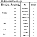
図4は、基本ユニット内モジュールテーブル230の構成の一例を示す。
本明細書および特許請求の範囲では、壁、各ユニットの床、間仕切り、階段、ロフト、手すり等のように建築時にひとまとまりとして施工されるものをモジュールといい、特に間仕切り、階段、ロフト、手すり等のようにユニットの内部に配置されるモジュールをユニット内モジュールという。
基本ユニット内モジュールは、ユニット内モジュールの1種であり、予め定められた大きさを有する。基本ユニット内モジュールテーブル230には、基本ユニット内モジュールの構成を示す基本ユニット内モジュール情報が格納される。図4に示すように、基本ユニット内モジュール情報は、基本ユニット内モジュール種別と、基本ユニット内モジュール識別情報と、構成と、縮小画像とを含む。
基本ユニット内モジュール種別は、間仕切りと階段とロフトと手すりとを含む。基本ユニット内モジュール識別情報は基本ユニット内モジュールを一意に識別する識別情報である。縮小画像は、基本ユニット内モジュールの縮小画像であり、ログハウスの一部または全体を2次元表示または3次元表示するときに使用される。
基本ユニット内モジュールを拡大または縮小することにより若しくはそのままで、所定の設計基準を満たす範囲内で任意の大きさのユニット内モジュールを形成することができる。
FIG. 4 shows an example of the configuration of the basic unit module table 230.
In this specification and claims, what is constructed as a unit during construction, such as walls, floors of each unit, partitions, stairs, lofts, handrails, etc. is called a module, and in particular, partitions, stairs, lofts, handrails. A module arranged inside the unit as described above is called an in-unit module.
The basic unit module is one type of unit module and has a predetermined size. The basic unit module table 230 stores basic unit module information indicating the configuration of the basic unit module. As shown in FIG. 4, the basic unit module information includes a basic unit module type, basic unit module identification information, a configuration, and a reduced image.
The module type in the basic unit includes a partition, a staircase, a loft, and a handrail. The basic unit module identification information is identification information for uniquely identifying the basic unit module. The reduced image is a reduced image of the module in the basic unit, and is used when a part or the whole of the log house is displayed two-dimensionally or three-dimensionally.
An in-unit module of any size can be formed within a range that satisfies a predetermined design standard by enlarging or reducing the basic unit module or as it is.
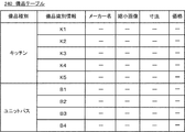
図5は、備品テーブル240の構成の一例を示す。
本明細書および特許請求の範囲では、キッチンやユニットバス等のように製造メーカーにより製造されるものであって、寸法が決まっており、ユニットの内部に配置されるものを備品という。
備品テーブル240には、備品の構成を示す備品情報が格納される。図5に示すように、備品情報は、備品種別と、備品識別情報と、メーカー名と、縮小画像と、寸法(縦×横×高さ)と、価格とを含む。
備品種別は、キッチンとユニットバスを含む。備品識別情報は、備品を一意に識別する識別情報である。縮小画像は、備品の縮小画像であり、ログハウスの一部または全体を2次元表示または3次元表示するときに使用される。価格は、備品の価格である。
FIG. 5 shows an example of the configuration of the equipment table 240.
In the present specification and claims, what is manufactured by a manufacturer such as a kitchen or a unit bath, whose dimensions are determined, and is arranged inside the unit is referred to as a fixture.
The equipment table 240 stores equipment information indicating the construction of equipment. As shown in FIG. 5, the equipment information includes equipment classification, equipment identification information, manufacturer name, reduced image, dimensions (vertical × horizontal × height), and price.
By equipment type includes kitchen and unit bath. The equipment identification information is identification information for uniquely identifying equipment. The reduced image is a reduced image of equipment, and is used when a part or the whole of the log house is displayed two-dimensionally or three-dimensionally. The price is the price of the equipment.
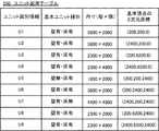
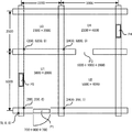
図6と図7は、それぞれユニット配置テーブル250と開口配置テーブル260の構成の一例を示す。図8と図9は、それぞれログハウスの1階と2階の構造の一例を示す。図10は、ログハウスの左側面図の一例である。なお、図8〜図10に示すログハウスは、図6のユニット配置テーブル250と図7の開口配置テーブル260の情報に基づいて構成されるものである。
図6のユニット配置テーブル250には、各ユニットの配置を示すユニット配置情報が格納される。図6に示すように、ユニット配置情報は、ユニット識別情報と、基本ユニット種別と、内寸(縦×横)と、基準頂点の3次元座標とを含む。
ユニット識別情報は、各ユニットを一意に識別する識別情報である。
基本ユニット種別には、基本ユニットテーブル210の基本ユニット種別のいずれかが設定される。
内寸(縦×横)は、各ユニットの底面の内寸である。
各ユニットの基準頂点は、各ユニットの底面においてユニット内部に面する矩形の頂点の一つである。例えば、図8と図9に示す各ユニットの底面の左下隅における×印が基準頂点を示す。基準頂点の3次元座標は、1階の床の所定の位置を原点とし、各ユニットにおける基準頂点の(横位置,縦位置、高さ)を示す。例えば、図8の例では、原点=(0,0,0)はログハウスの1階の床における左下隅のログハウス外部に面した頂点である。
なお、内寸(縦×横)と基準頂点の3次元座標は各ユニットについて大きさおよび配置される位置を表すが、これらを、各ユニットの底面の4つの頂点の3次元座標で表すこともできる。
6 and 7 show examples of configurations of the unit arrangement table 250 and the opening arrangement table 260, respectively. 8 and 9 show examples of the structure of the first floor and the second floor of the log house, respectively. FIG. 10 is an example of a left side view of the log house. The log house shown in FIGS. 8 to 10 is configured based on information of the unit arrangement table 250 in FIG. 6 and the opening arrangement table 260 in FIG.
The unit arrangement table 250 shown in FIG. 6 stores unit arrangement information indicating the arrangement of each unit. As shown in FIG. 6, the unit arrangement information includes unit identification information, basic unit type, internal dimensions (vertical × horizontal), and three-dimensional coordinates of the reference vertex.
The unit identification information is identification information that uniquely identifies each unit.
One of the basic unit types in the basic unit table 210 is set as the basic unit type.
The internal dimension (vertical x horizontal) is the internal dimension of the bottom surface of each unit.
The reference vertex of each unit is one of rectangular vertices facing the inside of the unit on the bottom surface of each unit. For example, the x mark at the lower left corner of the bottom surface of each unit shown in FIGS. 8 and 9 indicates the reference vertex. The three-dimensional coordinates of the reference vertex indicate the (vertical position, vertical position, height) of the reference vertex in each unit with the predetermined position of the floor on the first floor as the origin. For example, in the example of FIG. 8, the origin = (0, 0, 0) is a vertex facing the outside of the log house at the lower left corner of the floor of the first floor of the log house.
The internal dimensions (vertical x horizontal) and the three-dimensional coordinates of the reference vertex represent the size and position of each unit, but these may be represented by the three-dimensional coordinates of the four vertices on the bottom surface of each unit. it can.
図8〜図10に示すログハウスの例では、ログ材の幅は200mmであり、1階と2階の高さはそれぞれ2400mmである。
例えば、図8のユニットU1は壁有・床有ユニットであって1階の部屋である。ユニットU1の基準頂点の3次元座標は(200,200,0)であり、その内寸は5800mm×2000mmである。
図9のユニットU5は壁無・床有ユニットであって2階に位置する。ユニットU5の基準頂点の3次元座標は(200,200,2400)であり、その内寸は1800mm×2000mmである。ユニットU5の上の側面と右の側面にはそれぞれユニットU6およびユニットU7と共通の壁が形成される。ユニットU5の壁の無い2つの側面には、所定の設計基準に従って柱が設置される。なお、ユニットU5の壁の無い2つの側面において破線で示す矩形の領域の幅もログ材の幅と同様に200mmである。
また、図8のユニットU2は壁有・床有ユニットであって1階に位置する。ユニットU2の基準頂点の3次元座標は(2400,200,0)であり、その内寸は5800mm×4800mmである。図9に示すように、ユニットU2の上の2階には、ユニットU7が配置される。ユニットU7は壁有・床無ユニットであって吹き抜けを構成する。ユニットU7の基準頂点の3次元座標は(2400,200,2400)であり、その内寸は5800mm×4800mmである。
In the example of the log house shown in FIGS. 8 to 10, the width of the log material is 200 mm, and the heights of the first floor and the second floor are 2400 mm, respectively.
For example, the unit U1 in FIG. 8 is a wall / floor unit and is a room on the first floor. The three-dimensional coordinates of the reference vertex of the unit U1 are (200, 200, 0), and the inner dimension is 5800 mm × 2000 mm.
The unit U5 in FIG. 9 is a wallless / floored unit and is located on the second floor. The three-dimensional coordinates of the reference vertex of the unit U5 are (200, 200, 2400), and the inner dimension is 1800 mm × 2000 mm. A wall common to the unit U6 and the unit U7 is formed on the upper side surface and the right side surface of the unit U5, respectively. Pillars are installed on two side surfaces of the unit U5 without walls according to a predetermined design standard. Note that the width of the rectangular region indicated by the broken line on the two side surfaces of the unit U5 without a wall is also 200 mm, similar to the width of the log material.
Further, the unit U2 in FIG. 8 is a wall / floor unit and is located on the first floor. The three-dimensional coordinates of the reference vertex of the unit U2 are (2400, 200, 0), and the inner dimension is 5800 mm × 4800 mm. As shown in FIG. 9, the unit U7 is arranged on the second floor above the unit U2. The unit U7 is a walled / floorless unit and forms an atrium. The three-dimensional coordinates of the reference vertex of the unit U7 are (2400, 200, 2400), and the inner dimension is 5800 mm × 4800 mm.
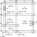
図11は、開口の位置を表示する方法の一例を示す。
操作画面上で横に延びる壁(以下、横向きの壁という。)に配置されている開口を利用者がポインティングデバイスで選択する(たとえば、マウスでクリックする)と、その開口の横方向の配置が操作画面に表示される。その配置は、ログ材で構成される左の壁の内面から開口までの間隔(以下、左の間隔という。)と、開口の幅と、ログ材で構成される右の壁の内面から開口までの間隔(以下、右の間隔という。)とで示される。更に、高さ方向の配置を指定する必要がある場合には、開口の高さと、床から開口の底面までの高さとが示される。ただし、開口の高さと床から開口の底面までの高さとが予め定められている固定の値である場合には、これらの表示は省略される。
これらの各値は、利用者がポインティングデバイスで数字を選択すると、テキストボックスに変わり、テキストボックス内に数値を入力することができる。
なお、各ユニットの内寸(縦の長さ×横幅)も同様に、利用者がポインティングデバイスで数字を選択すると、テキストボックスに変わり、テキストボックス内に数値を入力することができる。
FIG. 11 shows an example of a method for displaying the position of the opening.
When a user selects (for example, clicks with a mouse) an opening arranged on a wall that extends horizontally on the operation screen (hereinafter referred to as a horizontal wall), the horizontal arrangement of the opening is changed. Displayed on the operation screen. The arrangement is from the inner surface of the left wall made of log material to the opening (hereinafter referred to as the left interval), the width of the opening, and from the inner surface of the right wall made of log material to the opening. (Hereinafter referred to as the right interval). Further, when it is necessary to specify the arrangement in the height direction, the height of the opening and the height from the floor to the bottom surface of the opening are shown. However, when the height of the opening and the height from the floor to the bottom surface of the opening are predetermined fixed values, these displays are omitted.
Each of these values is changed to a text box when the user selects a number with the pointing device, and a numerical value can be entered in the text box.
Similarly, the internal size (vertical length × horizontal width) of each unit is changed to a text box when the user selects a number with a pointing device, and a numerical value can be entered in the text box.
基本開口テーブル220に含まれる基本開口情報で指定される基本開口をポインティングデバイスで選択して壁の上に置き、基本開口を拡大や縮小等することにより、壁に開口が形成される。この状態で、ユニットの横幅または開口の幅が変更されると、ユニットの横幅または開口の幅の変更に応じて左の間隔と右の間隔は両方とも変わる。
しかし、過去の操作において左の間隔が数値で入力された場合、ポインティングデバイスによる操作または数値の入力によってユニットの横幅が変更されるか、もしくは数値の入力によって開口の幅が変更されると、左の間隔はその数値に固定されたまま、ユニットの横幅または開口の幅の変更に応じて右の間隔のみが変わる。また、過去の操作において右の間隔が数値で入力された場合、ポインティングデバイスによる操作または数値の入力によってユニットの横幅が変更されるか、もしくは数値の入力によって開口の幅が変更されると、右の間隔はその数値に固定されたまま、ユニットの横幅または開口の幅の変更に応じて左の間隔のみが変わる。左の間隔と右の間隔が両方入力された場合には、最後に入力された間隔が優先される。
ただし、ポインティングデバイスによる操作によって開口の幅が変更された場合、過去の操作において左の間隔または右の間隔が入力されているときであっても、左の間隔と右の間隔はポインティングデバイスによる操作に依存して変更される。
An opening is formed in the wall by selecting the basic opening specified by the basic opening information included in the basic opening table 220 with a pointing device and placing the basic opening on the wall and enlarging or reducing the basic opening. In this state, when the width of the unit or the width of the opening is changed, both the left interval and the right interval change in accordance with the change in the width of the unit or the width of the opening.
However, if the left interval is entered as a numerical value in the past operation, if the width of the unit is changed by an operation with a pointing device or a numerical input, or the opening width is changed by a numerical input, While the interval of is fixed at that value, only the right interval changes according to the change of the width of the unit or the width of the opening. In addition, when the right interval is input as a numerical value in the past operation, if the width of the unit is changed by the operation of the pointing device or the input of the numerical value, or the opening width is changed by the input of the numerical value, The distance between the left and the left is changed according to the change in the width of the unit or the width of the opening while the distance is fixed. When both the left interval and the right interval are input, the interval input last is given priority.
However, if the opening width is changed by an operation with a pointing device, the left and right intervals are controlled by the pointing device even if the left interval or the right interval has been input in the previous operation. Will be changed depending on.
同様に、操作画面上で縦に延びる壁(縦向きの壁)に配置されている開口を利用者がポインティングデバイスで選択すると、その開口の縦方向の配置が操作画面に表示される。その配置は、ログ材で構成される上の壁の内面から開口までの間隔(上の間隔)と、開口の幅と、ログ材で構成される下の壁の内面から開口までの間隔(下の間隔)とで示される。更に、高さ方向の配置を指定する必要がある場合には、開口の高さと、床から開口の底面までの高さとが示される。ただし、開口の高さと床からの高さとが予め定められている固定の値である場合には、これらの表示は省略される。
これらの各値は、利用者がポインティングデバイスで数字を選択すると、テキストボックスに変わり、テキストボックス内に数値を入力することができる。
基本開口テーブル220に含まれる基本開口情報で指定される基本開口をポインティングデバイスで選択して壁の上に置き、基本開口を拡大や縮小等することにより、開口が配置される。この状態で、ユニットの縦の長さまたは開口の幅が変更されると、ユニットの縦の長さまたは開口の幅の変更に応じて上の間隔と下の間隔は両方とも変わる。
しかし、過去の操作において上の間隔が数値で入力された場合、ユニットの縦の長さまたは開口の幅が変更されると、上の間隔はその数値に固定されたまま、ポインティングデバイスによる操作または数値の入力によってユニットの縦の長さが変更されるか、もしくは数値の入力によって開口の幅が変更されると、下の間隔のみが変わる。逆に、過去の操作において下の間隔が数値で入力された場合、ポインティングデバイスによる操作または数値の入力によってユニットの縦の長さが変更されるか、もしくは数値の入力によって開口の幅が変更されると、下の間隔はその数値に固定されたまま、ユニットの縦の長さまたは開口の幅の変更に応じて上の間隔のみが変わる。上の間隔と下の間隔が両方数値で入力された場合には、最後に入力された間隔が優先される。
ただし、ポインティングデバイスによる操作によって開口の幅が変更された場合、過去の操作において上の間隔または下の間隔が入力されているときであっても、上の間隔と下の間隔はポインティングデバイスによる操作に依存して変更される。
Similarly, when the user selects an opening arranged on a vertically extending wall (vertical wall) on the operation screen with the pointing device, the vertical arrangement of the opening is displayed on the operation screen. The layout consists of the distance from the inner surface of the upper wall made of log material to the opening (upper distance), the width of the opening, and the distance from the inner surface of the lower wall made of log material to the opening (lower ). Further, when it is necessary to specify the arrangement in the height direction, the height of the opening and the height from the floor to the bottom surface of the opening are shown. However, when the height of the opening and the height from the floor are predetermined fixed values, these displays are omitted.
Each of these values is changed to a text box when the user selects a number with the pointing device, and a numerical value can be entered in the text box.
The basic opening specified by the basic opening information included in the basic opening table 220 is selected by a pointing device and placed on the wall, and the opening is arranged by enlarging or reducing the basic opening. In this state, when the vertical length of the unit or the width of the opening is changed, both the upper distance and the lower distance change according to the change of the vertical length of the unit or the width of the opening.
However, if the upper interval is entered as a numerical value in the past operation, if the vertical length of the unit or the width of the opening is changed, the upper interval remains fixed at that value, and the operation or If the vertical length of the unit is changed by inputting a numerical value, or if the width of the opening is changed by inputting a numerical value, only the lower interval changes. Conversely, if the lower interval was entered as a numerical value in the past operation, the vertical length of the unit is changed by the operation of the pointing device or the numerical value input, or the opening width is changed by the numerical value input. Then, the lower interval is fixed to the numerical value, and only the upper interval changes according to the change in the vertical length of the unit or the width of the opening. If both the upper and lower intervals are entered numerically, the interval entered last takes precedence.
However, when the width of the opening is changed by an operation with a pointing device, the upper and lower intervals are controlled by the pointing device even when the upper interval or the lower interval is input in the past operation. Will be changed depending on.
図7の開口配置テーブル260には、各開口の配置を示す開口配置情報が格納される。図7に示すように、開口配置情報は、開口識別情報と、基本開口識別情報と、壁識別情報と、配置と、間隔入力とを含む。
開口識別情報は、各開口を一意に識別する識別情報である。
基本開口識別情報には、基本開口テーブル220に格納されている基本開口情報に含まれる基本開口識別情報のいずれかが設定される。
壁識別情報は、開口が配置される壁を示す。図7では、壁識別情報を例えば「U1の下の壁」で示したが、これは1例に過ぎず、3次元座標等他の方法で開口が配置される壁を特定してもよい。
配置は、横向きの壁に配置されている開口の場合、左の間隔と、開口の幅と、右の間隔とを示す。また、縦向きの壁に配置されている開口の場合、上の間隔と、開口の幅と、下の間隔とを示す。
間隔入力には、横向きの壁に配置されている開口の場合、未、左、または右が設定される。ここで、未は左の間隔と右の間隔のいずれも入力されていない(未設定)であることを示す。左は左の間隔が最後に入力(設定)されたことを示す。右は右の間隔が最後に入力(設定)されたことを示す。また、縦向きの壁に配置されている開口の場合、間隔入力には、未、上、または下が設定される。ここで、未は上の間隔と下の間隔のいずれも入力されていない(未設定)であることを示す。上は上の間隔が最後に入力(設定)されたことを示す。下は下の間隔が最後に入力(設定)されたことを示す。
The opening arrangement table 260 in FIG. 7 stores opening arrangement information indicating the arrangement of each opening. As shown in FIG. 7, the opening arrangement information includes opening identification information, basic opening identification information, wall identification information, arrangement, and interval input.
The opening identification information is identification information for uniquely identifying each opening.
In the basic opening identification information, any of the basic opening identification information included in the basic opening information stored in the basic opening table 220 is set.
The wall identification information indicates the wall on which the opening is arranged. In FIG. 7, the wall identification information is indicated by “wall under U1”, for example, but this is only an example, and the wall on which the opening is arranged may be specified by other methods such as three-dimensional coordinates.
In the case of an opening arranged on a lateral wall, the arrangement indicates a left interval, an opening width, and a right interval. In the case of openings arranged in a vertically oriented wall, the upper interval, the width of the opening, and the lower interval are shown.
For the interval input, in the case of an opening arranged on a horizontal wall, non-, left, or right is set. Here, “not yet” indicates that neither the left interval nor the right interval is input (not set). The left indicates that the left interval was last input (set). The right indicates that the right interval was last input (set). Further, in the case of an opening arranged on a vertically oriented wall, the interval input is set to not, above, or below. Here, “not yet” indicates that neither the upper interval nor the lower interval is input (not set). The top indicates that the top interval was last entered (set). The bottom indicates that the bottom interval was last entered (set).
例えば、図8に示す開口P1は扉である。開口P1の寸法はメーカの定めた規格寸法である。開口P1はユニットU1の下の壁に配置されている。開口P1の左の間隔と幅と右の間隔は、それぞれ700と600と700である。
また、図8に示す開口P3は解放である。開口P3はユニットU2とユニットU4の間の壁に配置されている。開口P3の左の間隔と幅と右の間隔は、それぞれ1000と1000と2800である。
図9に示す開口P5は窓である。開口P5の寸法は特寸である。開口5はユニットU7の右の壁に配置されている。開口P5の上の間隔と幅と下の間隔は、それぞれ2200と1400と2200である。
For example, the opening P1 shown in FIG. 8 is a door. The dimension of the opening P1 is a standard dimension determined by the manufacturer. The opening P1 is arranged on the lower wall of the unit U1. The left interval, width, and right interval of the opening P1 are 700, 600, and 700, respectively.
Further, the opening P3 shown in FIG. 8 is released. The opening P3 is disposed in the wall between the unit U2 and the unit U4. The left interval, the width, and the right interval of the opening P3 are 1000, 1000, and 2800, respectively.
The opening P5 shown in FIG. 9 is a window. The dimension of the opening P5 is a special size. The opening 5 is arranged on the right wall of the unit U7. The upper interval, the width, and the lower interval of the opening P5 are 2200, 1400, and 2200, respectively.
図12は、ユニット内に配置されるユニット内モジュールと備品の位置を表示する方法の一例を示す。
ユニット内に配置されているユニット内モジュールまたは備品を利用者がポインティングデバイスで選択すると、そのユニット内モジュールまたは備品の配置が操作画面に表示される。その配置は、ユニット内モジュールまたは備品の大きさ(縦の長さ×横幅)を中心として、上側にログ材で構成される上の壁の内面からユニット内モジュールまたは備品までの間隔(以下、上の間隔という。)、下側にログ材で構成される下の壁の内面からユニット内モジュールまたは備品までの間隔(以下、下の間隔という。)、左側にログ材で構成される左の壁の内面からユニット内モジュールまたは備品までの間隔(以下、左の間隔という。)、および右側にログ材で構成される右の壁の内面からユニット内モジュールまたは備品までの間隔(以下、右の間隔という。)で示される。更に、高さ方向の配置を指定する必要がある場合には、ユニット内モジュールまたは備品の高さと、床からユニット内モジュールまたは備品の底面までの高さとが示される。ただしユニット内モジュールまたは備品の高さと床からユニット内モジュールまたは備品の底面までの高さが予め定められている固定の値である場合には、これらの表示は省略される。
これらの各値は、数字をポインティングデバイスで選択すると、テキストボックスに変わり、テキストボックス内に数値を入力することができる。
なお、図9のユニットU5のような壁無ユニット内にユニット内モジュールまたは備品が配置された場合、矩形の破線で示される壁に相当する領域を壁とみなして、上述したユニット内モジュールまたは備品の配置が操作画面に表示される。
また、ユニット内モジュールまたは備品が壁に接触している場合、すなわち壁の内面からユニット内モジュールまたは備品までの間隔が0である場合には、その表示を省略することとしてもよい。
FIG. 12 shows an example of a method for displaying the position of modules and equipment arranged in the unit.
When the user selects a module or fixture in the unit arranged in the unit with the pointing device, the arrangement of the module or fixture in the unit is displayed on the operation screen. The arrangement is centered on the size of the module or fixture in the unit (vertical length x width), and the distance from the inner surface of the upper wall made of log material on the upper side to the module or fixture in the unit (hereinafter referred to as upper ), The distance from the inner surface of the lower wall made of log material on the lower side to the module or fixture in the unit (hereinafter referred to as the lower space), and the left wall made of log material on the left side The distance from the inner surface of the unit to the module or equipment in the unit (hereinafter referred to as the left distance), and the distance from the inner surface of the right wall made of log material on the right side to the module or the equipment in the unit (hereinafter referred to as the right distance) It is indicated by.) Further, when it is necessary to specify the arrangement in the height direction, the height of the module or equipment in the unit and the height from the floor to the bottom surface of the module or equipment in the unit are shown. However, when the height of the module or fixture in the unit and the height from the floor to the bottom surface of the module or fixture in the unit are predetermined fixed values, these displays are omitted.
Each of these values changes to a text box when a number is selected with a pointing device, and a numerical value can be entered in the text box.
In addition, when the module or fixture in a unit is arrange | positioned in the unit without a wall like the unit U5 of FIG. 9, the area | region equivalent to the wall shown with a rectangular broken line is considered as a wall, and the module or fixture in a unit mentioned above Is displayed on the operation screen.
Further, when the module or fixture in the unit is in contact with the wall, that is, when the interval from the inner surface of the wall to the module or fixture in the unit is 0, the display may be omitted.
基本ユニット内モジュールテーブル230に含まれる基本ユニット内モジュール情報で指定される基本ユニット内モジュールをポインティングデバイスで選択してユニット内に置き、基本ユニット内モジュールを拡大や縮小等することにより、ユニット内モジュールが配置される。また、備品テーブル240に含まれる備品情報で指定される備品をポインティングデバイスで選択してユニット内に置くことにより、備品が配置される。なお、備品の大きさは固定であって変更することはできない。この状態で、ユニットの大きさまたはユニット内モジュールの大きさが変更されると、変更された大きさに応じて上の間隔と下の間隔の両方および/または左の間隔と右の間隔の両方が変わる。 The module in the unit is selected by selecting the module in the basic unit specified by the module information in the basic unit included in the module table 230 in the basic unit with the pointing device and enlarging or reducing the module in the basic unit. Is placed. The equipment is arranged by selecting the equipment specified by the equipment information included in the equipment table 240 with a pointing device and placing it in the unit. The size of the equipment is fixed and cannot be changed. In this state, if the unit size or the size of the module in the unit is changed, both the upper and lower intervals and / or both the left and right intervals depending on the changed size. Changes.
しかし、過去の操作において左の間隔が数値で入力された場合、ポインティングデバイスによる操作または数値の入力によってユニットの横幅が変更されるか、もしくは数値の入力によってユニット内モジュールの横幅が変更されると、左の間隔はその数値に固定されたまま、ユニットの横幅またはユニット内モジュールの横幅の変更に応じて右の間隔のみが変わる。また、過去の操作において右の間隔が数値で入力された場合、ポインティングデバイスによる操作または数値の入力によってユニットの横幅が変更されるか、もしくは数値の入力によってユニット内モジュールの横幅が変更されると、右の間隔はその数値に固定されたまま、ユニットの横幅またはユニット内モジュールの横幅の変更に応じて左の間隔のみが変わる。左の間隔と右の間隔が両方数値で入力された場合には、最後に入力された間隔が優先される。
ただし、ポインティングデバイスによる操作によってユニット内モジュールの横幅が変更された場合、過去の操作において左の間隔または右の間隔が入力されているときであっても、左の間隔と右の間隔はポインティングデバイスによる操作に依存して変更される。
However, if the left interval is entered as a numerical value in the past operation, if the horizontal width of the unit is changed by an operation with a pointing device or a numerical value input, or the horizontal width of the module in the unit is changed by numerical value input The left interval is fixed to the value, and only the right interval changes according to the change in the width of the unit or the width of the module in the unit. In addition, when the right interval is input as a numerical value in the past operation, the horizontal width of the unit is changed by an operation with the pointing device or the input of the numerical value, or the horizontal width of the module in the unit is changed by the numerical value input. The right interval is fixed to the numerical value, and only the left interval changes according to the change in the width of the unit or the width of the module in the unit. If both the left and right intervals are entered numerically, the interval entered last takes precedence.
However, if the horizontal width of the module in the unit is changed by an operation with a pointing device, the left and right intervals are not changed even if the left interval or the right interval is input in the past operation. It is changed depending on the operation.
同様に、過去の操作において上の間隔が数値で入力された場合、ポインティングデバイスによる操作または数値の入力によってユニットの縦の長さが変更されるか、もしくは数値の入力によってユニット内モジュールの縦の長さが変更されると、上の間隔はその数値に固定されたまま、ユニットの縦の長さまたはユニット内モジュールの縦の長さの変更に応じて下の間隔のみが変わる。また、過去の操作において下の間隔が数値で入力された場合、ポインティングデバイスによる操作または数値の入力によってユニットの縦の長さが変更されるか、もしくは数値の入力によってユニット内モジュールの縦の長さが変更されると、下の間隔はその数値に固定されたまま、ユニットの縦の長さまたはユニット内モジュールの縦の長さの変更に応じて上の間隔のみが変わる。上の間隔と下の間隔が両方数値で入力された場合には、最後に入力された間隔が優先される。
ただし、ポインティングデバイスによる操作によってユニット内モジュールの縦の長さが変更された場合、過去の操作において上の間隔または下の間隔が入力されているときであっても、左の間隔と右の間隔はポインティングデバイスによる操作に依存して変更される。
Similarly, in the past operation, when the upper interval is entered as a numerical value, the vertical length of the unit is changed by an operation with a pointing device or the input of a numerical value, or the vertical length of the module in the unit is changed by the input of a numerical value. When the length is changed, the upper interval remains fixed at the value, and only the lower interval changes according to the change in the vertical length of the unit or the vertical length of the module in the unit. In addition, if the lower interval is entered as a numerical value in the past operation, the vertical length of the unit is changed by the operation of the pointing device or the input of the numerical value, or the vertical length of the module in the unit by the numerical input. When the height is changed, the lower distance remains fixed at the value, and only the upper distance changes according to the change in the vertical length of the unit or the vertical length of the module in the unit. If both the upper and lower intervals are entered numerically, the interval entered last takes precedence.
However, if the vertical length of the module in the unit is changed by an operation with a pointing device, even if the upper interval or the lower interval has been input in the past operation, the left interval and the right interval Is changed depending on the operation by the pointing device.
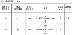
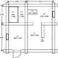
図13と図14は、それぞれユニット内モジュール配置テーブル270と備品配置テーブル280の構成の一例を示す。図15と図16は、それぞれログハウスの1階と2階にユニット内モジュールと備品が配置された一例を示す。なお、図15と図16に示すユニット内モジュールと備品は、図13のユニット内モジュール配置テーブル270と図14の備品配置テーブル280の情報に基づいて配置されたものである。
図13のユニット内モジュール配置テーブル270には、ユニット内モジュールの配置を示すユニット内モジュール配置情報が格納される。ユニット内モジュール配置情報は、ユニット内モジュール識別情報と、基本ユニット内モジュール識別情報と、ユニット識別情報と、配置と、横間隔入力と、縦間隔入力とを含む。
ユニット内モジュール識別情報は、ログハウス内に配置されている各ユニット内モジュールを一意に識別する識別情報である。
基本ユニット内モジュール識別情報には、基本ユニット内モジュールテーブル230に格納されている基本ユニット内モジュール情報に含まれる基本ユニット内モジュール識別情報のいずれかが設定される。
ユニット識別情報には、ユニット配置テーブル250に格納されているユニット配置情報に含まれるユニット識別情報のいずれかが格納される。ユニット識別情報は、ユニット内モジュールが配置されるユニットを指定する。
配置は、ユニット内モジュールの寸法(縦の長さ×横幅)と、上の間隔と、下の間隔と、左の間隔と、右の間隔とを含む。また、必要に応じて、配置は、ユニット内モジュールの高さと、床からユニット内モジュールの底面までの高さとを含む。
横間隔入力には、未、左、または右が設定される。ここで、未は左の間隔と右の間隔のいずれも入力されていない(未設定)であることを示す。左は左の間隔が最後に入力(設定)されたことを示す。右は右の間隔が最後に入力(設定)されたことを示す。
縦間隔入力には、未、上、または下が設定される。ここで、未は上の間隔と下の間隔のいずれも入力されていない(未設定)であることを示す。上は上の間隔が最後に入力(設定)されたことを示す。下は下の間隔が最後に入力(設定)されたことを示す。
FIG. 13 and FIG. 14 show examples of configurations of the in-unit module arrangement table 270 and the equipment arrangement table 280, respectively. FIG. 15 and FIG. 16 show an example in which the modules and equipment in the unit are arranged on the first floor and the second floor of the log house, respectively. 15 and 16 are arranged based on information in the in-unit module arrangement table 270 in FIG. 13 and the equipment arrangement table 280 in FIG.
The in-unit module arrangement table 270 of FIG. 13 stores in-unit module arrangement information indicating the arrangement of in-unit modules. The intra-unit module arrangement information includes intra-unit module identification information, basic unit module identification information, unit identification information, arrangement, horizontal interval input, and vertical interval input.
The intra-unit module identification information is identification information for uniquely identifying each intra-unit module arranged in the log house.
In the basic unit module identification information, any of the basic unit module identification information included in the basic unit module information stored in the basic unit module table 230 is set.
In the unit identification information, any of the unit identification information included in the unit arrangement information stored in the unit arrangement table 250 is stored. The unit identification information specifies a unit in which the unit module is arranged.
The arrangement includes the dimensions of the module in the unit (vertical length × width), the upper space, the lower space, the left space, and the right space. Further, the arrangement includes the height of the module in the unit and the height from the floor to the bottom surface of the module in the unit as necessary.
The horizontal interval input is set to not yet, left, or right. Here, “not yet” indicates that neither the left interval nor the right interval is input (not set). The left indicates that the left interval was last input (set). The right indicates that the right interval was last input (set).
The vertical interval input is set to not yet, above, or below. Here, “not yet” indicates that neither the upper interval nor the lower interval is input (not set). The top indicates that the top interval was last entered (set). The bottom indicates that the bottom interval was last entered (set).
図15に示すユニット内モジュールM1は縦間仕切りP1である。ユニット内モジュールM1はユニットU2内に配置される。ユニット内モジュールM1の長さは300cmである。ユニット内モジュールM1の幅は、例えばログ材の幅(20cm)である。ユニット内モジュールM1の高さは、予め1階の高さ(2.4m)と定められている。ユニット内モジュールM1の幅と高さは表示されない。ユニット内モジュールM1は、上端がユニットU2の上の壁に接触しており、下端がユニットU2の下の壁から2.8m離れている。ユニット内モジュールM1は、ユニットU2の左の壁から2m離れており、ユニットU2の右の壁から2.7m離れている。
横間隔入力に右が設定されているため、ユニットU2の横幅が変更されると、右の壁との間隔2.7mを保って左の壁との間隔が変わる。また、縦間隔入力に上が設定されているため、ユニットU2の縦の長さが変更されると、上の壁と接触したまま、下の壁との間隔が変わる。
The in-unit module M1 shown in FIG. 15 is a vertical partition P1. The intra-unit module M1 is disposed in the unit U2. The length of the in-unit module M1 is 300 cm. The width of the in-unit module M1 is, for example, the width of the log material (20 cm). The height of the in-unit module M1 is determined in advance as the height of the first floor (2.4 m). The width and height of the in-unit module M1 are not displayed. In the unit module M1, the upper end is in contact with the upper wall of the unit U2, and the lower end is 2.8 m away from the lower wall of the unit U2. The intra-unit module M1 is 2 m away from the left wall of the unit U2 and 2.7 m away from the right wall of the unit U2.
Since the right is set as the lateral distance input, when the lateral width of the unit U2 is changed, the distance from the left wall is changed while the distance from the right wall is maintained at 2.7 m. In addition, since the top is set for the vertical interval input, when the vertical length of the unit U2 is changed, the interval with the lower wall is changed while being in contact with the upper wall.
図16に示すユニット内モジュールM2はI字階段S1である。ユニット内モジュールM2はユニットU2内に配置される。ユニット内モジュールM2の大きさは350cm×80cmである。ユニット内モジュールM2の高さは、ユニット内モジュールM3(LT)の高さで決まり、それと同一であるため、表示されない。ユニット内モジュールM2は、上端がユニットU2の上の壁から1.2m離れており(ユニット内モジュールM3に接触しており)、下端がユニットU2の下の壁から1.1m離れている。ユニット内モジュールM2は、ユニットU2の左の壁から2.5m離れており、ユニットU2の右の壁から1.5m離れている。
横間隔入力に右が設定されているため、ユニットU2の横幅が変更されると、右の壁との間隔1.5mを保って左の壁との間隔が変わる。また、縦間隔入力に上が設定されているため、ユニットU2の縦の長さが変更されると、ユニット内モジュールM3と接触したまま、下の壁との間隔が変わる。
The in-unit module M2 shown in FIG. 16 is an I-shaped staircase S1. The intra-unit module M2 is disposed in the unit U2. The size of the unit module M2 is 350 cm × 80 cm. The height of the in-unit module M2 is determined by the height of the in-unit module M3 (LT), and is the same as that, so it is not displayed. The in-unit module M2 has an upper end that is 1.2 m away from the upper wall of the unit U2 (in contact with the in-unit module M3), and a lower end that is 1.1 m away from the lower wall of the unit U2. The intra-unit module M2 is 2.5 m away from the left wall of the unit U2 and 1.5 m away from the right wall of the unit U2.
Since the right is set as the lateral distance input, when the lateral width of the unit U2 is changed, the distance from the left wall is changed while the distance from the right wall is maintained at 1.5 m. Further, since “up” is set for the vertical interval input, when the vertical length of the unit U2 is changed, the interval with the lower wall changes while being in contact with the in-unit module M3.
図16に示すユニット内モジュールM3はロフトLTである。ユニット内モジュールM3はユニットU2内に配置される。ユニット内モジュールM3の大きさは120cm×480cmである。ユニット内モジュールM3の1階床からの高さは、240cmである。ロフトLTには床からの高さを任意に設定し、またそれを変更できるため、ユニット内モジュールM3については1階床からの高さが表示される。ユニット内モジュールM3は、上端がユニットU2の上の壁に接触しており、下端がユニットU2の下の壁から4.6m離れている。ユニット内モジュールM3は、ユニットU2の左の壁と右の壁に接触している。
横間隔入力には未が設定されているが、ユニット内モジュールM3はユニットU2の左右の壁に接触しているため、ユニットU2の横幅が変更されるとき、ユニット内モジュールM3は、ユニットU2の左右の壁との接触を保ったまま、その横幅が変わる。また、縦間隔入力に上が設定されているため、ユニットU2の縦の長さが変更されると、ユニット内モジュールM3は、ユニットU2の上の壁と接触したまま、下の壁との間隔が変わる。
The in-unit module M3 shown in FIG. 16 is a loft LT. The intra-unit module M3 is disposed in the unit U2. The size of the unit module M3 is 120 cm × 480 cm. The height from the first floor of the in-unit module M3 is 240 cm. Since the height from the floor can be set arbitrarily in the loft LT and can be changed, the height from the first floor is displayed for the in-unit module M3. In the unit module M3, the upper end is in contact with the upper wall of the unit U2, and the lower end is 4.6 m away from the lower wall of the unit U2. The intra-unit module M3 is in contact with the left wall and the right wall of the unit U2.
Although the horizontal interval input is not set, since the in-unit module M3 is in contact with the left and right walls of the unit U2, when the lateral width of the unit U2 is changed, the in-unit module M3 The width changes while maintaining contact with the left and right walls. In addition, since the vertical distance input is set to “up”, when the vertical length of the unit U2 is changed, the in-unit module M3 remains in contact with the upper wall of the unit U2 and is spaced from the lower wall. Changes.
図16に示すユニット内モジュールM4は柵手すりR1である。ユニット内モジュールM4はユニット内モジュールM3(ロフトLT)の端(ユニットU7内)に設置される。ユニット内モジュールM4の大きさは10cm×250cmである。ユニット内モジュールM4の高さは、100cmである。柵手すりR1には任意の高さを設定し、またそれを変更できるため、ユニット内モジュールM4についてはその高さが表示される。ユニット内モジュールM4は、上端がユニットU7の上の壁から1.1m離れており、下端がユニットU7の下の壁から4.6m離れている。ユニット内モジュールM4は、ユニットU7の左の壁に接触している。
横間隔入力には左が設定されているため、ユニットU7の横幅が変更されるとき、ユニット内モジュールM4は、ユニットU7の左の壁と接触したまま、右の壁との間隔が変わる。また、縦間隔入力に上が設定されているため、ユニットU7の縦の長さが変更されるとき、ユニット内モジュールM4は、ユニットU7の上の壁と接触したまま、下の壁との間隔が変わる。
The in-unit module M4 shown in FIG. 16 is a fence handrail R1. The intra-unit module M4 is installed at the end (in the unit U7) of the intra-unit module M3 (loft LT). The size of the unit module M4 is 10 cm × 250 cm. The height of the unit module M4 is 100 cm. Since an arbitrary height can be set for the railing handrail R1 and can be changed, the height of the module M4 in the unit is displayed. The in-unit module M4 has an upper end that is 1.1 m away from the upper wall of the unit U7 and a lower end that is 4.6 m away from the lower wall of the unit U7. The intra-unit module M4 is in contact with the left wall of the unit U7.
Since the left is set for the horizontal interval input, when the horizontal width of the unit U7 is changed, the in-unit module M4 changes the interval with the right wall while being in contact with the left wall of the unit U7. In addition, since the vertical length input is set to “up”, when the vertical length of the unit U7 is changed, the in-unit module M4 is in contact with the upper wall of the unit U7 and is spaced from the lower wall. Changes.
図16に示すユニット内モジュールM5も柵手すりR1である。ユニット内モジュールM5もユニット内モジュールM3(ロフトLT)の端(ユニットU7内)に設置される。ユニット内モジュールM5の大きさは10cm×150cmである。ユニット内モジュールM5の高さは、100cmである。ユニット内モジュールM4と同様にユニット内モジュールM5についてもその高さが表示される。ユニット内モジュールM5は、上端がユニットU7の上の壁から1.1m離れており、下端がユニットU7の下の壁から4.6m離れている。ユニット内モジュールM5は、ユニットU7の右の壁に接触している。
横間隔入力には右が設定されているため、ユニットU7の横幅が変更されるとき、ユニット内モジュールM5は、ユニットU7の右の壁と接触したまま、左の壁との間隔が変わる。また、縦間隔入力に上が設定されているため、ユニットU7の縦の長さが変更されると、ユニット内モジュールM5は、ユニットU7の上の壁と接触したまま、下の壁との間隔が変わる。
The in-unit module M5 shown in FIG. 16 is also a railing handrail R1. The intra-unit module M5 is also installed at the end (in the unit U7) of the intra-unit module M3 (loft LT). The size of the unit module M5 is 10 cm × 150 cm. The height of the unit module M5 is 100 cm. Similarly to the in-unit module M4, the height of the in-unit module M5 is also displayed. The in-unit module M5 has an upper end that is 1.1 m away from the upper wall of the unit U7 and a lower end that is 4.6 m away from the lower wall of the unit U7. The intra-unit module M5 is in contact with the right wall of the unit U7.
Since the right is set for the horizontal interval input, when the horizontal width of the unit U7 is changed, the in-unit module M5 changes the interval with the left wall while being in contact with the right wall of the unit U7. In addition, since the vertical length input is set to “up”, when the vertical length of the unit U7 is changed, the in-unit module M5 is in contact with the upper wall of the unit U7 and is spaced from the lower wall. Changes.
図16に示すユニット内モジュールM6は四角間仕切りP4である。ユニット内モジュールM6はユニットU9内に配置される。ユニット内モジュールM6の大きさは90cm×280cmである。ユニット内モジュールM6は、上端がユニットU9の上の壁から70cm離れており、下端がユニットU9の下の壁から70cm離れている。ユニット内モジュールM6は、左端がユニットU9の左の壁から100cm離れており、右端がユニットU9の右の壁から100cm離れている。
横間隔入力と縦間隔入力に両方とも未が設定されているため、ユニット内モジュールM6は、ユニットU9の大きさが変更されると、変更された大きさに応じて上の間隔と下の間隔の両方および/または左の間隔と右の間隔の両方が変わる。
The in-unit module M6 shown in FIG. 16 is a square partition P4. The intra-unit module M6 is disposed in the unit U9. The size of the unit module M6 is 90 cm × 280 cm. The intra-unit module M6 has an upper end that is 70 cm away from the upper wall of the unit U9 and a lower end that is 70 cm away from the lower wall of the unit U9. The intra-unit module M6 has a left end that is 100 cm away from the left wall of the unit U9 and a right end that is 100 cm away from the right wall of the unit U9.
Since both the horizontal interval input and the vertical interval input are not set, when the size of the unit U9 is changed, the in-unit module M6 has an upper interval and a lower interval according to the changed size. And / or both the left and right spacings vary.
図14の備品配置テーブル280には、備品の配置を示す備品配置情報が格納される。備品配置情報は、配置備品識別情報と、備品識別情報と、ユニット識別情報と、配置と、横間隔入力と、縦間隔入力とを含む。
配置備品識別情報は、ログハウス内に配置されている各備品を一意に識別する識別情報である。
備品識別情報には、備品テーブル240に格納されている備品情報に含まれる備品識別情報のいずれかが設定される。
ユニット識別情報には、ユニット配置テーブル250に格納されているユニット配置情報に含まれるユニット識別情報のいずれかが格納される。ユニット識別情報は、備品が配置されるユニットを指定する。
配置は、備品の寸法(縦の長さ×横幅)と、上の間隔と、下の間隔と、左の間隔と、右の間隔とを含む。
横間隔入力には、未、左、または右が設定される。ここで、未は左の間隔と右の間隔のいずれも入力されていない(未設定)であることを示す。左は左の間隔が最後に入力(設定)されたことを示す。右は右の間隔が最後に入力(設定)されたことを示す。
縦間隔入力には、未、上、または下が設定される。ここで、未は上の間隔と下の間隔のいずれも入力されていない(未設定)であることを示す。上は上の間隔が最後に入力(設定)されたことを示す。下は下の間隔が最後に入力(設定)されたことを示す。
The equipment arrangement table 280 in FIG. 14 stores equipment arrangement information indicating the arrangement of equipment. The equipment arrangement information includes arrangement equipment identification information, equipment identification information, unit identification information, arrangement, horizontal interval input, and vertical interval input.
The arrangement equipment identification information is identification information for uniquely identifying each equipment arranged in the log house.
In the equipment identification information, any of the equipment identification information included in the equipment information stored in the equipment table 240 is set.
In the unit identification information, any of the unit identification information included in the unit arrangement information stored in the unit arrangement table 250 is stored. The unit identification information specifies the unit where the equipment is placed.
The arrangement includes the dimensions of the fixture (vertical length × width), the top spacing, the bottom spacing, the left spacing, and the right spacing.
The horizontal interval input is set to not yet, left, or right. Here, “not yet” indicates that neither the left interval nor the right interval is input (not set). The left indicates that the left interval was last input (set). The right indicates that the right interval was last input (set).
The vertical interval input is set to not yet, above, or below. Here, “not yet” indicates that neither the upper interval nor the lower interval is input (not set). The top indicates that the top interval was last entered (set). The bottom indicates that the bottom interval was last entered (set).
図15に示す備品E1はユニットバスB1である。備品E1はユニットU3内に配置される。備品E1の大きさは230cm×100cmである。備品E1は、ユニットU3の上の壁と下の壁に接触している。備品E1は、ユニットU3の左の壁と接触しており、ユニットU3の右の壁から1m離れている。
横間隔入力に左が設定されているため、ユニットU3の横幅が変更されると、備品E1は左の壁と接触したまま、右の間隔が変わる。備品の大きさは固定であって変更することはできないため、ユニットU3は縦方向には縮小できず、拡大できるのみである。縦間隔入力に未が設定されているが、ユニットU3が縦方向に拡大されると、備品E1はその拡大に応じて上の間隔と下の間隔が両方とも広がる。
The equipment E1 shown in FIG. 15 is a unit bus B1. The fixture E1 is arranged in the unit U3. The size of the fixture E1 is 230 cm × 100 cm. The fixture E1 is in contact with the upper wall and the lower wall of the unit U3. The fixture E1 is in contact with the left wall of the unit U3 and is 1 m away from the right wall of the unit U3.
Since the left is set for the horizontal interval input, when the horizontal width of the unit U3 is changed, the right interval changes while the fixture E1 is in contact with the left wall. Since the size of the fixture is fixed and cannot be changed, the unit U3 cannot be reduced in the vertical direction but can only be enlarged. Although the vertical interval input is not set, when the unit U3 is expanded in the vertical direction, both the upper interval and the lower interval of the fixture E1 are expanded according to the expansion.
図15に示す備品E2はキッチンK2である。備品E2はユニットU4内に配置される。備品E2の大きさは50cm×200cmである。備品E2は、ユニットU4の上の壁から80cm離れており、下の壁から1m離れている。備品E2は、ユニットU4の左の壁と接触しており、ユニットU4の右の壁から2.8m離れている。
横間隔入力に左が設定されているため、ユニットU4の横幅が変更されると、備品E2は左の壁と接触したまま、右の間隔が変わる。縦間隔入力に上が設定されているため、ユニットU4の縦の長さが変更されると、備品E2は上の間隔を保ったまま、その変更に応じて下の間隔が変わる。
The fixture E2 shown in FIG. 15 is a kitchen K2. The fixture E2 is arranged in the unit U4. The size of the fixture E2 is 50 cm × 200 cm. The fixture E2 is 80 cm away from the upper wall of the unit U4 and 1 m away from the lower wall. The fixture E2 is in contact with the left wall of the unit U4 and is 2.8 m away from the right wall of the unit U4.
Since the left is set for the horizontal interval input, when the horizontal width of the unit U4 is changed, the right interval changes while the fixture E2 is in contact with the left wall. Since the upper is set for the vertical interval input, when the vertical length of the unit U4 is changed, the lower interval changes according to the change while the fixture E2 maintains the upper interval.
図17は、設計基準テーブル290の構成の一例を示す。
設計基準テーブル290には、所定の設計基準を示す設計基準情報が格納される。設計基準情報は、適用箇所と、設計基準とを含む。図17に示す設計基準は一部であり、設計基準テーブル290はその他に多数の設計基準を含む。
利用者の操作が、設計基準テーブル290に格納されている設計基準に違反する場合、ユニット配置部101等の各部は、出力装置310等に表示される操作画面に警告を表示する。
なお、設計基準は、設計基準テーブル290の形ではなく、建物用CADプログラム201のコードとして記述されてもよい。
FIG. 17 shows an example of the configuration of the design criteria table 290.
The design criteria table 290 stores design criteria information indicating predetermined design criteria. The design criteria information includes application locations and design criteria. The design criteria shown in FIG. 17 are a part, and the design criteria table 290 includes many other design criteria.
When the user's operation violates the design criteria stored in the design criteria table 290, each unit such as the
The design criteria may be described not as the design criteria table 290 but as codes of the
以下、図1に示した各部の機能について説明する。
ユニット配置部101は、基本ユニットテーブル210に格納されている基本ユニット情報に含まれる基本ユニット種別で示される各基本ユニットを出力装置400等の操作画面に表示する。利用者は例えばポインティングデバイスを用いて基本ユニットの一つを選択して、出力装置400等に表示されている操作画面上に置く。そして利用者は、必要に応じて操作画面上でそれを拡大または縮小する操作を行う。
ユニット配置部101は、利用者の操作に従って、基本ユニットテーブル210に格納されている基本ユニット情報を選択し、選択された基本ユニット情報に含まれる基本ユニット種別で示される基本ユニットを操作画面に配置し、それを拡大または縮小して若しくはそのままでユニットを形成する。ユニット配置部101は、形成されたユニットにユニット識別情報を付与する。
Hereinafter, the function of each unit shown in FIG. 1 will be described.
The
The
そして、ユニット配置部101は、2つの壁有ユニットが隣り合わせに配置されるとき、これら両ユニットの境の壁を共通化し、両ユニットの境界に1つの壁を配置する。また、ユニット配置部101は、壁無ユニットと壁有ユニットとが隣り合わせに配置されるとき、これら両ユニットのユニットの境において壁有ユニットの壁を優先し、両ユニットの境界に1つの壁を配置する。ユニット配置部101は、壁無ユニットの壁の無い側面に、設計基準テーブル290に格納されている所定の設計基準を満たすように所定の間隔で柱を配置する。最後に、ユニット配置部101は、設計基準テーブル290に格納されているログ材の幅(壁の厚さ)と各階の高さとを含む情報に基づいてユニットの基準頂点の3次元座標を求めてユニット配置情報を作成し、作成されたユニット配置情報をユニット配置テーブル250に格納する。
When the two wall-mounted units are arranged next to each other, the
開口配置部102は、基本開口テーブル220に格納されている基本開口情報に含まれる基本開口識別情報で識別される各基本開口を出力装置400等の操作画面に表示する。利用者は例えばポインティングデバイスを用いて基本開口の一つを選択して、操作画面上でユニットの壁に置く。そして利用者は、必要に応じて操作画面上でそれを拡大または縮小する操作を行う。
開口配置部102は、利用者の操作に従って、基本開口テーブル220に格納されている基本開口情報を選択し、選択された基本開口情報に含まれる基本開口識別情報で識別される基本開口を、ユニット配置部101によって求められた位置に配置されているユニットの壁に配置する。そして、開口配置部102は、それを拡大または縮小することにより若しくはそのままでユニットの壁に開口を形成する。開口配置部102は、形成された開口に開口識別情報を付与する。そして、開口配置部102は、開口が配置される壁の壁識別情報と、開口の配置とを求めて開口配置情報を作成し、形成された開口の開口配置情報を開口配置テーブル240に格納する。このとき、開口配置情報の間隔入力は「未」に設定されている。
The
The
1階と2階の設計が終了すると、建物用CADシステム100は、利用者の操作に従って2階の上に屋根を配置し、屋根の配置を示す屋根配置情報を作成する。ただし、屋根の設計は本発明の範囲外であるため、屋根の設計についての説明は省略する。
モジュール形成部103は、ユニット配置テーブル250に格納されているユニット配置情報と屋根配置情報とに基づいて、ユニット配置部101によって同一の平面上に配置された壁を、ひとまとまりとして施工される1つの壁にまとめる。次に、モジュール形成部103は、この1つにまとめられた壁に、開口配置部102によって形成された開口に対応する孔を形成する。そして、モジュール形成部103は、その壁の壁配置情報を作成する。
図18は、ログハウスの設計が完成したとき、モジュール形成部103によって形成されるログハウスの左側面の壁の一例を示す。
また、モジュール形成部103は、ユニット配置情報に基づいて、各部屋の床の床配置情報を作成する。
When the design of the first floor and the second floor is completed, the building CAD system 100 arranges a roof on the second floor in accordance with a user operation, and creates roof arrangement information indicating the arrangement of the roof. However, since the roof design is out of the scope of the present invention, the description of the roof design is omitted.
The
FIG. 18 shows an example of the wall on the left side of the log house formed by the
Moreover, the
ユニット内モジュール配置部104は、基本ユニット内モジュールテーブル230に格納されている基本ユニット内モジュール情報に含まれる基本ユニット内モジュール識別情報で指定される各基本ユニット内モジュールを出力装置400等の操作画面に表示する。利用者は例えばポインティングデバイスを用いて基本ユニット内モジュールの一つを選択して、操作画面上でユニット内に置く。ユニット内モジュール配置部104は、ユニット内モジュールを生成するために必要な情報、例えば、階段の場合は段数の入力を求める。利用者は、その情報を入力する。そして、利用者は、必要に応じて操作画面上でユニット内モジュールを拡大または縮小する操作を行う。
ユニット内モジュール配置部104は、利用者の操作に従って、基本ユニット内モジュールテーブル230に格納されている基本ユニット内モジュール情報を選択し、選択された基本ユニット内モジュール情報に含まれる基本ユニット内モジュール識別情報で指定される基本ユニット内モジュールを生成し、ユニット内に配置する。ユニット内モジュール配置部104は、それを拡大または縮小することにより若しくはそのままでユニット内にユニット内モジュールを形成する。ユニット内モジュール配置部104は、形成されたユニット内モジュールにユニット内モジュール識別情報を付与する。そして、ユニット内モジュール配置部104は、ユニット内モジュールが配置されるユニットのユニット識別情報と、ユニット内モジュールの配置とを求めてユニット内モジュール配置情報を作成し、そのユニット内モジュール配置情報をユニット内モジュール配置テーブル270に格納する。このとき、ユニット内モジュール配置情報の横間隔入力と縦間隔入力は両方とも「未」に設定されている。
The in-unit
The in-unit
備品配置部105は、備品テーブル240に格納されている備品情報に含まれる備品識別情報で指定される各備品を出力装置400等の操作画面に表示する。利用者は例えばポインティングデバイスを用いて備品の一つを選択して、操作画面上でユニット内に置く。
備品配置部105は、利用者の操作に従って、備品テーブル240に格納されている備品情報を選択し、選択された備品をユニット内に配置する。備品配置部105は、配置された備品に配置備品識別情報を付与する。そして、備品配置部105は、備品が配置されるユニットのユニット識別情報と、備品の配置とを求めて備品配置情報を作成し、その備品配置情報を備品配置テーブル280に格納する。このとき、備品配置情報の横間隔入力と縦間隔入力は両方とも「未」に設定されている。
The
The
配置変更部106は、開口、ユニット内モジュール、または備品が利用者の操作によって選択されると、選択されたものの配置を操作画面に表示する。そして、配置変更部106は、利用者によって入力される配置の変更を受け付けて、開口配置テーブル260、ユニット内モジュール配置テーブル270、および備品配置テーブル280内の配置を変更する。
When an opening, an in-unit module, or a fixture is selected by a user operation, the
操作画面上で横向きの壁または縦向きの壁に配置されている開口を利用者がポインティングデバイスで選択すると、配置変更部106はその開口の開口配置情報を開口配置テーブル260から読み出す。図11に示したように、配置変更部106は読み出した開口配置情報に含まれる開口の配置を操作画面に表示する。その配置は、左の間隔と開口の幅と右の間隔、または上の間隔と開口の幅と下の間隔を含む。更に、高さ方向の配置を指定する必要がある場合には、その配置は、開口の高さと床から開口の底面までの高さとを含む。ただし、開口の高さと床から開口の底面までの高さとが予め定められている固定の値である場合には、これらの表示は省略される。
利用者がポインティングデバイスで選択して、左の間隔と開口の幅と右の間隔のいずれか、または上の間隔と開口の幅と下の間隔のいずれかを示す数字を選択すると、配置変更部106はこれらの各値をテキストボックスに変更し、テキストボックス内に入力された数値を受け付ける。
When the user selects an opening arranged on a horizontal wall or a vertical wall on the operation screen with the pointing device, the
When the user selects with a pointing device and selects a number indicating either the left interval, the width of the opening and the right interval, or the upper interval, the width of the opening, and the lower interval, 106 changes each of these values to a text box, and accepts a numerical value entered in the text box.
上述したように、利用者がポインティングデバイスで基本開口を選択して壁の上に置くと、開口配置部102は、基本開口を壁の上に配置する。そして、開口配置部102は、利用者のポインティングデバイスによる操作に従って、その基本開口を拡大や縮小等することにより、壁に開口を形成する。このとき、開口配置テーブル260に格納されている開口配置情報の間隔入力には「未」が設定されている。この状態で、利用者が開口の幅の数値を入力すると、配置変更部106は、開口の幅を変更するとともに、開口の幅の変更に応じて左の間隔と右の間隔の両方、または上の間隔と下の間隔の両方を変更する。
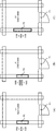
例えば、開口配置情報の間隔入力に「未」が設定されており、図19(A)に示すように開口P2(窓W1)の幅が2000である場合に、図19(B)に示すように利用者が2000という数字を選択し、テキストボックス内に3000という数字を入力する。このとき、配置変更部106は、図19(C)に示すように、上の間隔と下の間隔をそれぞれ1400mmに変更する。そして、配置変更部106は、開口配置テーブル260に格納されている開口配置情報の配置を1400+3000+1400に変更する。このとき、開口配置情報の間隔入力は「未」のままである。
As described above, when the user selects the basic opening with the pointing device and places it on the wall, the
For example, when “not yet” is set in the interval input of the opening arrangement information and the width of the opening P2 (window W1) is 2000 as shown in FIG. 19A, as shown in FIG. The user selects the
また、横向きの壁に配置された開口において、左の間隔が選択されて左の間隔に数値が入力された場合、配置変更部106は、開口配置テーブル260に格納されている開口配置情報の間隔入力に「右」と「左」のいずれが設定されていても、左の間隔をその数値に変更し、その変更に応じて右の間隔も変更する。そして、配置変更部106は、開口配置テーブル260に格納されている開口配置情報の配置を変更し、間隔入力に「左」を設定する。
横向きの壁に配置された開口において、右の間隔が選択されて右の間隔に数値が入力された場合、配置変更部106は、開口配置テーブル260に格納されている開口配置情報の間隔入力に「右」と「左」のいずれが設定されていても、右の間隔をその数値に変更し、その変更に応じて左の間隔も変更する。そして、配置変更部106は、開口配置テーブル260に格納されている開口配置情報の配置を変更し、間隔入力に「左」を設定する。
なお、左の間隔と右の間隔の両方に数値が入力された場合、配置変更部106は、最後に入力された間隔に対応して開口配置テーブル260に格納されている開口配置情報の間隔入力に「右」または「左」を設定する。
In addition, in the opening arranged on the sideways wall, when the left interval is selected and a numerical value is input to the left interval, the
When the right interval is selected and the numerical value is input to the right interval in the openings arranged on the sideways wall, the
When numerical values are input to both the left interval and the right interval, the
同様に、縦向きの壁に配置された開口において、上の間隔が選択されて上の間隔に数値が入力された場合、配置変更部106は、開口配置テーブル260に格納されている開口配置情報の間隔入力に「上」と「下」のいずれが設定されていても、上の間隔をその数値に変更し、その変更に応じて下の間隔も変更する。そして、配置変更部106は、開口配置テーブル260に格納されている開口配置情報の配置を変更し、間隔入力に「上」を設定する。
縦向きの壁に配置された開口において、下の間隔が選択されて下の間隔に数値が入力された場合、配置変更部106は、開口配置テーブル260に格納されている開口配置情報の間隔入力に「上」と「下」のいずれが設定されていても、下の間隔をその数値に変更し、その変更に応じて上の間隔も変更する。そして、配置変更部106は、開口配置テーブル260に格納されている開口配置情報の配置を変更し、間隔入力に「下」を設定する。
なお、上の間隔と下の間隔の両方に数値が入力された場合、配置変更部106は、最後に入力された間隔に対応して開口配置テーブル260に格納されている開口配置情報の間隔入力に「上」または「下」を設定する。
Similarly, when an upper interval is selected and a numerical value is input to the upper interval in the openings arranged on the vertical wall, the
In the opening arranged on the vertical wall, when the lower interval is selected and a numerical value is input to the lower interval, the
When numerical values are input to both the upper interval and the lower interval, the
例えば、図20(A)に示すように開口P1(扉D1)の右の間隔が700である場合に、図20(B)に示すように利用者が右の間隔の700という数字を選択し、テキストボックス内に1000という数字を入力する。このとき、配置変更部106は、開口配置情報の間隔入力に「右」と「左」のいずれが設定されていても、図20(C)に示すように左の間隔と右の間隔をそれぞれ400mmと1000mmに変更する。そして、配置変更部106は、開口配置テーブル260に格納されている開口配置情報の配置を400+600+1000に変更し、間隔入力に「右」を設定する。
For example, when the right interval of the opening P1 (door D1) is 700 as shown in FIG. 20 (A), the user selects the
また、横向きの壁に配置された開口において、開口配置テーブル260に格納されている開口配置情報の間隔入力に「左」が設定されている状態で、数値の入力によって開口の幅が変更されると、配置変更部106は、左の間隔はその数値に固定したまま、開口の幅の変更に応じて右の間隔のみを変更する。そして、配置変更部106は、開口配置テーブル260に格納されている開口配置情報の配置を変更する。
横向きの壁に配置された開口において、開口配置テーブル260に格納されている開口配置情報の間隔入力に「右」が設定されている状態で、数値の入力によって開口の幅が変更されると、配置変更部106は、右の間隔はその数値に固定したまま、開口の幅の変更に応じて左の間隔のみを変更する。そして、配置変更部106は、開口配置テーブル260に格納されている開口配置情報の配置を変更する。
In addition, in the opening arranged on the horizontal wall, the width of the opening is changed by inputting a numerical value in a state where “left” is set in the interval input of the opening arrangement information stored in the opening arrangement table 260. Then, the
When the opening width is changed by inputting a numerical value in the state where “right” is set in the interval input of the opening arrangement information stored in the opening arrangement table 260 in the opening arranged on the sideways wall, The
同様に、縦向きの壁に配置された開口において、開口配置テーブル260に格納されている開口配置情報の間隔入力に「上」が設定されている状態で、数値の入力によって開口の幅が変更されると、配置変更部106は、上の間隔はその数値に固定したまま、開口の幅の変更に応じて下の間隔のみを変更する。そして、配置変更部106は、開口配置テーブル260に格納されている開口配置情報の配置を変更する。
縦向きの壁に配置された開口において、開口配置テーブル260に格納されている開口配置情報の間隔入力に「下」が設定されている状態で、数値の入力によって開口の幅が変更されると、配置変更部106は、下の間隔はその数値に固定したまま、開口の幅の変更に応じて上の間隔のみを変更する。そして、配置変更部106は、開口配置テーブル260に格納されている開口配置情報の配置を変更する。
Similarly, in the opening arranged on the vertical wall, the width of the opening is changed by inputting a numerical value when “upper” is set in the interval input of the opening arrangement information stored in the opening arrangement table 260. Then, the
When the opening width is changed by inputting a numerical value in the state where “down” is set in the interval input of the opening arrangement information stored in the opening arrangement table 260 in the opening arranged on the vertical wall. The
例えば、開口P2(窓W1)の開口配置情報の間隔入力に「下」が設定されており、図20(A)に示すように開口P2(窓W1)の幅が2000である場合に、図20(B)に示すように利用者が2000という数字を選択し、テキストボックス内に3000という数字を入力する。このとき、配置変更部106は、図20(C)に示すように、下の間隔は1900mmに固定したまま、上の間隔を900mmに変更する。そして、配置変更部106は、開口配置テーブル260に格納されている開口配置情報の配置を900+3000+1900に変更する。このとき、開口配置情報の間隔入力は「下」のままである。
For example, when “lower” is set in the interval input of the opening arrangement information of the opening P2 (window W1) and the width of the opening P2 (window W1) is 2000 as shown in FIG. As shown in 20 (B), the user selects the
操作画面上でユニット内に配置されているユニット内モジュールを利用者がポインティングデバイスで選択すると、配置変更部106はそのユニット内モジュールのユニット内モジュール配置情報をユニット内モジュール配置テーブル270から読み出す。そして、図12に示したように、配置変更部106は読み出したユニット内モジュール配置情報に含まれるユニット内モジュールの配置を操作画面に表示する。その配置は、ユニット内モジュールの大きさ(縦の長さ×横幅)を中心として、上の間隔と、下の間隔と、左の間隔と、右の間隔とを含む。更に、高さ方向の配置を指定する必要がある場合には、ユニット内モジュールの高さと、床からユニット内モジュールの底面までの高さとを含む。ただしユニット内モジュールの高さと床からユニット内モジュールの底面までの高さが予め定められている固定の値である場合には、これらの表示は省略される。
利用者がポインティングデバイスで選択して、ユニット内モジュールの大きさ(縦の長さ×横幅)、上の間隔、下の間隔、左の間隔、または右の間隔を示す数字を選択すると、配置変更部106はこれらの各値をテキストボックスに変更し、テキストボックス内に入力された数値を受け付ける。
なお、図9のユニットU5のような壁無ユニット内にユニット内モジュールを配置する場合、配置変更部106は、矩形の破線で示される壁に相当する領域を壁とみなして、上述したユニット内モジュールの配置を操作画面に表示する。
また、ユニット内モジュールが壁に接触している場合、すなわち壁の内面からユニット内モジュールまでの間隔が0である場合、配置変更部106は、その表示を省略することとしてもよい。
When the user selects an in-unit module arranged in the unit on the operation screen with the pointing device, the
When the user selects with a pointing device and selects the number of modules in the unit (vertical length x width), top spacing, bottom spacing, left spacing, or right spacing, the layout changes. The
In the case where an in-unit module is arranged in a wallless unit such as the unit U5 in FIG. 9, the
When the module in the unit is in contact with the wall, that is, when the distance from the inner surface of the wall to the module in the unit is 0, the
上述したように、利用者がポインティングデバイスにより基本ユニット内モジュールを選択してユニット内に置くと、ユニット内モジュール配置部104は、基本ユニット内モジュールをユニット内に配置する。そして、ユニット内モジュール配置部104は、利用者のポインティングデバイスによる操作に従って、その基本ユニット内モジュールを拡大や縮小等することにより、ユニット内にユニット内モジュールを形成する。
このとき、ユニット内モジュール配置テーブル270に格納されているユニット内モジュール配置情報の横間隔入力と縦間隔入力には両方とも「未」が設定されている。この状態で、利用者がユニット内モジュールの縦の長さおよび/または横幅の数値を入力すると、配置変更部106は、ユニット内モジュールの縦の長さおよび/または横幅を変更するとともに、その変更に応じて上の間隔と下の間隔の両方、および/または左の間隔と右の間隔の両方を変更する。
As described above, when the user selects a module in the basic unit with the pointing device and places it in the unit, the module-in-
At this time, “not yet” is set for both the horizontal interval input and the vertical interval input of the intra-unit module arrangement information stored in the intra-unit module arrangement table 270. In this state, when the user inputs the vertical length and / or horizontal width values of the module in the unit, the
また、ユニット内に配置されたユニット内モジュールにおいて、上の間隔が選択されて上の間隔に数値が入力された場合、配置変更部106は、ユニット内モジュール配置テーブル270に格納されているユニット内モジュール配置情報の縦間隔入力に「上」と「下」のいずれが設定されていても、上の間隔をその数値に変更し、その変更に応じて下の間隔も変更する。そして、配置変更部106は、ユニット内モジュール配置情報の配置を変更し、縦間隔入力に「上」を設定する。
ユニット内に配置されたユニット内モジュールにおいて、下の間隔が選択されて下の間隔に数値が入力された場合、配置変更部106は、ユニット内モジュール配置テーブル270に格納されているユニット内モジュール配置情報の縦間隔入力に「上」と「下」のいずれが設定されていても、下の間隔をその数値に変更し、その変更に応じて上の間隔も変更する。そして、配置変更部106は、ユニット内モジュール配置情報の配置を変更し、縦間隔入力に「下」を設定する。
なお、上の間隔と下の間隔の両方に数値が入力された場合、配置変更部106は、最後に入力された間隔に対応してユニット内モジュール配置テーブル270に格納されているユニット内モジュール配置情報の縦間隔入力に「上」または「下」を設定する。
In addition, in the module within the unit arranged in the unit, when the upper interval is selected and a numerical value is input to the upper interval, the
In the unit module arranged in the unit, when the lower interval is selected and a numerical value is input to the lower interval, the
When numerical values are input to both the upper interval and the lower interval, the
同様に、ユニット内に配置されたユニット内モジュールにおいて、左の間隔が選択されて左の間隔に数値が入力された場合、配置変更部106は、ユニット内モジュール配置テーブル270に格納されているユニット内モジュール配置情報の横間隔入力に「左」と「右」のいずれが設定されていても、左の間隔をその数値に変更し、その変更に応じて右の間隔も変更する。そして、配置変更部106は、ユニット内モジュール配置情報の配置を変更し、横間隔入力に「左」を設定する。
ユニット内に配置されたユニット内モジュールにおいて、右の間隔が選択されて右の間隔に数値が入力された場合、配置変更部106は、ユニット内モジュール配置テーブル270に格納されているユニット内モジュール配置情報の横間隔入力に「左」と「右」のいずれが設定されていても、右の間隔をその数値に変更し、その変更に応じて左の間隔も変更する。そして、配置変更部106は、ユニット内モジュール配置情報の配置を変更し、横間隔入力に「右」を設定する。
なお、左の間隔と右の間隔の両方に数値が入力された場合、配置変更部106は、最後に入力された間隔に対応してユニット内モジュール配置テーブル270に格納されているユニット内モジュール配置情報の横間隔入力に「左」または「右」を設定する。
Similarly, in the unit module arranged in the unit, when the left interval is selected and a numerical value is input to the left interval, the
In the unit module arranged in the unit, when the right interval is selected and a numerical value is input to the right interval, the
When numerical values are input to both the left interval and the right interval, the
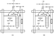
例えば、図21(A)に示すように、ユニット内モジュールM1(縦間仕切り)の右の間隔が2600である場合に、利用者が右の間隔の2600という数字を選択し、テキストボックス内に1600という数字を入力する。このとき、配置変更部106は、ユニット内モジュール配置情報の横間隔入力に「右」と「左」のいずれが設定されていても、図21(B)に示すように左の間隔と右の間隔をそれぞれ3000mmと1600mmに変更する。そして、配置変更部106は、ユニット内モジュール配置テーブル270に格納されているユニット内モジュール配置情報の配置における左の間隔と右の間隔をそれぞれ3000と1600に変更し、横間隔入力に「右」を設定する。
また、図21(A)に示すように、開口P3(解放)の右の間隔が2800である場合に、利用者が右の間隔の2800という数字を選択し、テキストボックス内に1800という数字を入力する。このとき、配置変更部106は、開口配置情報の間隔入力に「右」と「左」のいずれが設定されていても、図21(B)に示すように左の間隔と右の間隔をそれぞれ2000mmと1800mmに変更する。そして、配置変更部106は、開口配置テーブル260に格納されている開口配置情報の配置における左の間隔と右の間隔をそれぞれ2000と1800に変更し、間隔入力に「右」を設定する。
For example, as shown in FIG. 21A, when the right interval of the in-unit module M1 (vertical partition) is 2600, the user selects the
Further, as shown in FIG. 21A, when the right interval of the opening P3 (release) is 2800, the user selects the
例えば、図21(C)に示すように、ユニット内モジュールM2(I字階段)の右の間隔が1500である場合に、利用者が右の間隔の1500という数字を選択し、テキストボックス内に500という数字を入力する。このとき、配置変更部106は、ユニット内モジュール配置情報の横間隔入力に「右」と「左」のいずれが設定されていても、図21(D)に示すように左の間隔と右の間隔をそれぞれ3500mmと500mmに変更する。そして、配置変更部106は、ユニット内モジュール配置テーブル270に格納されているユニット内モジュール配置情報の配置における左の間隔と右の間隔をそれぞれ3500と500に変更し、横間隔入力に「右」を設定する。
For example, as shown in FIG. 21C, when the right interval of the in-unit module M2 (I-shaped staircase) is 1500, the user selects the number 1500 for the right interval and puts it in the text box. Enter the
例えば、図21(C)に示すように、ユニット内モジュールM4(柵手すり)の横幅が2500である場合に、利用者が横幅の2500という数字を選択し、テキストボックス内に3500という数字を入力する。このとき、配置変更部106は、ユニット内モジュール配置情報の横間隔入力に「左」が設定されているため、図21(D)に示すように、ユニット内モジュールM4とユニットU7の左の壁との接触を保ったまま、右の間隔を1300mmに変更する。そして、配置変更部106は、ユニット内モジュール配置テーブル270に格納されているユニット内モジュール配置情報の配置における右の間隔を1300に変更する。
また、例えば、図21(C)に示すように、ユニット内モジュールM5(柵手すり)の横幅が1500である場合に、利用者が横幅の1500という数字を選択し、テキストボックス内に500という数字を入力する。このとき、配置変更部106は、ユニット内モジュール配置情報の横間隔入力に「右」が設定されているため、図21(D)に示すように、ユニット内モジュールM5とユニットU7の右の壁との接触を保ったまま、左の間隔を4300mmに変更する。そして、配置変更部106は、ユニット内モジュール配置テーブル270に格納されているユニット内モジュール配置情報の配置における左の間隔を4300に変更する。
For example, as shown in FIG. 21C, when the width of the module M4 (fence railing) in the unit is 2500, the user selects the
In addition, for example, as shown in FIG. 21C, when the width of the module M5 (fence railing) in the unit is 1500, the user selects the number 1500 for the width and the
また、ユニット内に配置されたユニット内モジュールにおいて、ユニット内モジュール配置テーブル270に格納されているユニット内モジュール配置情報の横間隔入力に「左」が設定されている状態で、数値の入力によってユニット内モジュールの横幅が変更されると、配置変更部106は、左の間隔はその数値に固定したまま、横幅の変更に応じて右の間隔のみを変更する。そして、配置変更部106は、ユニット内モジュール配置情報の配置を変更する。
ユニット内に配置されたユニット内モジュールにおいて、ユニット内モジュール配置テーブル270に格納されているユニット内モジュール配置情報の横間隔入力に「右」が設定されている状態で、数値の入力によってユニット内モジュールの横幅が変更されると、配置変更部106は、右の間隔はその数値に固定したまま、横幅の変更に応じて左の間隔のみを変更する。そして、配置変更部106は、ユニット内モジュール配置情報の配置を変更する。
In addition, in the module within the unit arranged in the unit, the unit is entered by inputting a numerical value when “left” is set in the horizontal interval input of the module arrangement information in the unit stored in the module arrangement table 270 in the unit. When the horizontal width of the inner module is changed, the
In the unit module arranged in the unit, when the right-side input of the horizontal interval input of the module arrangement information in the unit stored in the module arrangement table 270 in the unit is set to “Right”, the module in the unit is entered by inputting a numerical value. When the horizontal width is changed, the
同様に、ユニット内に配置されたユニット内モジュールにおいて、ユニット内モジュール配置テーブル270に格納されているユニット内モジュール配置情報の縦間隔入力に「上」が設定されている状態で、数値の入力によってユニット内モジュールの縦の長さが変更されると、配置変更部106は、上の間隔はその数値に固定したまま、縦の長さの変更に応じて下の間隔のみを変更する。そして、配置変更部106は、ユニット内モジュール配置情報の配置を変更する。
ユニット内に配置されたユニット内モジュールにおいて、ユニット内モジュール配置テーブル270に格納されているユニット内モジュール配置情報の縦間隔入力に「下」が設定されている状態で、数値の入力によってユニット内モジュールの縦の長さが変更されると、配置変更部106は、下の間隔はその数値に固定したまま、縦の長さの変更に応じて上の間隔のみを変更する。
Similarly, in the unit module arranged in the unit, when “upper” is set in the vertical interval input of the unit module arrangement information stored in the unit module arrangement table 270, When the vertical length of the module in the unit is changed, the
In the unit module arranged in the unit, the value in the unit module arrangement information stored in the unit module arrangement table 270 is set to “down” in the vertical interval input of the unit module arrangement information. When the vertical length is changed, the
例えば、ユニット内モジュールM1(縦間仕切り)と開口P3(解放)が図21(B)に示した状態であり、ユニット内モジュールM2(I字階段)が図21(D)に示した状態である場合、ユニット内モジュールM1とユニット内モジュールM2の間隔は30cmである。また、ユニット内モジュールM1と開口P3の間隔は0である。このとき、図22に示すように、ポインティングデバイスによる操作または数値の入力によってユニットU2とユニットU7の横幅(内寸)を4800から4300に縮小しても、配置変更部106は、ユニット内モジュールM1とユニット内モジュールM2の間隔を30cmに保ち、同様にユニット内モジュールM1と開口P3の間隔を0に保つ。
1つのユニット内に複数のユニット内モジュールが配置されている場合、それらの複数のユニット内モジュールについて左の間隔に数値を入力した後に、ポインティングデバイスによる操作または数値の入力によってそのユニットを拡大または縮小してもユニット内モジュール間の横の間隔を保つことができる。右の間隔についても同様である。
同様に、1つのユニット内に複数のユニット内モジュールが配置されている場合、それらの複数のユニット内モジュールについて上の間隔に数値を入力した後に、ポインティングデバイスによる操作または数値の入力によってそのユニットを拡大または縮小してもユニット内モジュール間の縦の間隔を保つことができる。下の間隔についても同様である。
ログハウス全体を拡大または縮小する場合であっても、同様にログハウスを構成する各ユニットに含まれるユニット内モジュール間の縦と横の間隔を保つことができる。
For example, the in-unit module M1 (vertical partition) and the opening P3 (release) are in the state shown in FIG. 21B, and the in-unit module M2 (I-shaped staircase) is in the state shown in FIG. In this case, the interval between the in-unit module M1 and the in-unit module M2 is 30 cm. Further, the interval between the unit module M1 and the opening P3 is zero. At this time, as shown in FIG. 22, even if the horizontal width (inner dimensions) of the unit U2 and the unit U7 is reduced from 4800 to 4300 by an operation with a pointing device or input of numerical values, the
When multiple modules within a unit are arranged in one unit, after entering a numerical value in the left interval for these multiple modules within the unit, the unit is enlarged or reduced by an operation with a pointing device or by inputting a numerical value. Even in this case, it is possible to maintain a horizontal distance between the modules in the unit. The same applies to the right interval.
Similarly, when a plurality of in-unit modules are arranged in one unit, after inputting a numerical value in the upper interval for the plurality of in-unit modules, the unit is operated by operating with a pointing device or inputting a numerical value. Even when enlarged or reduced, the vertical spacing between the modules in the unit can be maintained. The same applies to the lower interval.
Even when the entire log house is enlarged or reduced, the vertical and horizontal distances between the modules in the units included in the units constituting the log house can be maintained.
ただし、ユニット内モジュールM4(柵手すり)とユニット内モジュールM5(柵手すり)とが図21(B)に示した状態である場合、ポインティングデバイスによる操作または数値の入力によってユニットU7の横幅(内寸)を4800から4300に縮小しても、図22(B)に示すように、ユニット内モジュールM4とユニット内モジュールM5の横幅は変わらない。このため、ユニット内モジュールM4とユニット内モジュールM5の間隔、すなわちユニット内モジュールM2(I字階段)からユニット内モジュールM3(ロフトLT)への入口の幅は30cmに減少する。
そこで、例えば、図23(A)に示すように、ユニット内モジュールM4とユニット内モジュールM5の代わりに、ユニット内モジュールM4A(柵手すり)を設置し、ユニット内モジュールにも扉や解放のような開口を配置できることとしてもよい。
ユニット内モジュールM4Aの大きさは10cm×480cmである。ユニット内モジュールM4Aの高さは、100cmである。ユニット内モジュールM4Aは、上端がユニットU7の上の壁から1.1m離れており、下端がユニットU7の下の壁から4.6m離れている。ユニット内モジュールM4Aは、ユニットU7の左の壁と右の壁に接触している。
横間隔入力には、「未」、「右」、「左」のいずれが設定されていてもよい。ユニットU7の横幅が変更されるとき、配置変更部106は、ユニット内モジュールM4Aと、ユニットU7の左右の壁との接触を保ったまま、ユニット内モジュールM4Aの横幅を変更する。また、縦間隔入力には上が設定されており、ユニットU7の縦の長さが変更されると、配置変更部106は、ユニット内モジュールM4AとユニットU7の上の壁との接触を保ったまま、下の壁との間隔を変更する。
開口P7(解放)は、ユニット内モジュールM4Aに配置される。図23(A)に示すように、縮小前の左の間隔と開口幅と右の間隔は、それぞれ3500mと800mと500mである。間隔入力には「右」が設定されている。
この場合、図23(B)に示すように、ユニットU7が縮小されても、ユニット内モジュールM2(I字階段)の上端と開口P7(解放)の位置は一致している。
However, when the in-unit module M4 (fence railing) and the in-unit module M5 (fence railing) are in the state shown in FIG. ) Is reduced from 4800 to 4300, as shown in FIG. 22B, the horizontal width of the in-unit module M4 and the in-unit module M5 does not change. Therefore, the distance between the in-unit module M4 and the in-unit module M5, that is, the width of the entrance from the in-unit module M2 (I-shaped staircase) to the in-unit module M3 (loft LT) is reduced to 30 cm.
Therefore, for example, as shown in FIG. 23A, instead of the in-unit module M4 and the in-unit module M5, an in-unit module M4A (fence handrail) is installed, and the in-unit module also has a door or a release. It is good also as being able to arrange an opening.
The size of the unit module M4A is 10 cm × 480 cm. The height of the unit module M4A is 100 cm. In the unit module M4A, the upper end is 1.1 m away from the upper wall of the unit U7, and the lower end is 4.6 m away from the lower wall of the unit U7. The intra-unit module M4A is in contact with the left wall and the right wall of the unit U7.
Any of “not yet”, “right”, and “left” may be set in the lateral interval input. When the lateral width of the unit U7 is changed, the
The opening P7 (release) is arranged in the in-unit module M4A. As shown in FIG. 23A, the left interval, the opening width, and the right interval before reduction are 3500 m, 800 m, and 500 m, respectively. “Right” is set for the interval input.
In this case, as shown in FIG. 23B, even if the unit U7 is reduced, the position of the upper end of the in-unit module M2 (I-shaped staircase) and the position of the opening P7 (release) coincide.
操作画面上でユニット内に配置されている備品を利用者がポインティングデバイスで選択すると、配置変更部106はその備品の備品配置情報を備品配置テーブル280から読み出す。そして、図12に示したように、配置変更部106は読み出した備品配置情報に含まれる備品の配置を操作画面に表示する。その配置は、備品の大きさ(縦の長さ×横幅)を中心として、上の間隔と、下の間隔と、左の間隔と、右の間隔とを含む。更に、高さ方向の配置を指定する必要がある場合には、備品の高さと、床から備品の底面までの高さとを含む。ただし備品の高さと床から備品の底面までの高さが予め定められている固定の値である場合には、これらの表示は省略される。
利用者がポインティングデバイスで選択して、上の間隔、下の間隔、左の間隔、または右の間隔を示す数字を選択すると、配置変更部106はこれらの各値をテキストボックスに変更し、テキストボックス内に入力された数値を受け付ける。
なお、図9のユニットU5のような壁無ユニット内に備品を配置する場合、配置変更部106は、矩形の破線で示される壁に相当する領域を壁とみなして、上述した備品の配置を操作画面に表示する。
また、備品が壁に接触している場合、すなわち壁の内面から備品までの間隔が0である場合、配置変更部106は、その表示を省略することとしてもよい。
When the user selects the equipment arranged in the unit on the operation screen with the pointing device, the
When the user selects with a pointing device and selects a number indicating an upper interval, a lower interval, a left interval, or a right interval, the
In addition, when arranging equipment in a wall-less unit like the unit U5 of FIG. 9, the
When the fixture is in contact with the wall, that is, when the distance from the inner surface of the wall to the fixture is 0, the
上述したように、利用者がポインティングデバイスで備品を選択してユニット内に置くと、備品配置部105は、備品をユニット内に配置する。
ユニット内に配置された備品において、上の間隔が選択されて上の間隔に数値が入力された場合、配置変更部106は、備品配置テーブル280に格納されている備品配置情報の縦間隔入力に「上」と「下」のいずれが設定されていても、上の間隔をその数値に変更し、その変更に応じて下の間隔も変更する。そして、配置変更部106は、備品配置情報の配置を変更し、縦間隔入力に「上」を設定する。
ユニット内に配置された備品において、下の間隔が選択されて下の間隔に数値が入力された場合、配置変更部106は、備品配置テーブル280に格納されている備品配置情報の縦間隔入力に「上」と「下」のいずれが設定されていても、下の間隔をその数値に変更し、その変更に応じて上の間隔も変更する。そして、配置変更部106は、備品配置情報の配置を変更し、縦間隔入力に「下」を設定する。
なお、上の間隔と下の間隔の両方に数値が入力された場合、配置変更部106は、最後に入力された間隔に対応して備品配置テーブル280に格納されている備品配置情報の縦間隔入力に「上」または「下」を設定する。
As described above, when the user selects equipment with the pointing device and places it in the unit, the
In the equipment arranged in the unit, when the upper interval is selected and a numerical value is input to the upper interval, the
In the equipment arranged in the unit, when the lower interval is selected and a numerical value is input to the lower interval, the
When numerical values are input to both the upper interval and the lower interval, the
同様に、ユニット内に配置された備品において、左の間隔が選択されて左の間隔に数値が入力された場合、配置変更部106は、備品配置テーブル280に格納されている備品配置情報の横間隔入力に「左」と「右」のいずれが設定されていても、左の間隔をその数値に変更し、その変更に応じて右の間隔も変更する。そして、配置変更部106は、備品配置情報の配置を変更し、横間隔入力に「左」を設定する。
ユニット内に配置された備品において、右の間隔が選択されて右の間隔に数値が入力された場合、配置変更部106は、備品配置テーブル280に格納されている備品配置情報の横間隔入力に「左」と「右」のいずれが設定されていても、右の間隔をその数値に変更し、その変更に応じて左の間隔も変更する。そして、配置変更部106は、備品配置情報の配置を変更し、横間隔入力に「右」を設定する。
なお、左の間隔と右の間隔の両方に数値が入力された場合、配置変更部106は、最後に入力された間隔に対応して備品配置テーブル280に格納されている備品配置情報の横間隔入力に「左」または「右」を設定する。
Similarly, in the equipment arranged in the unit, when the left interval is selected and a numerical value is input to the left interval, the
In the equipment arranged in the unit, when the right interval is selected and a numerical value is inputted to the right interval, the
When numerical values are input to both the left interval and the right interval, the
図22で説明したユニット内モジュールの例と同様に、1つのユニット内に複数の備品が配置されている場合、それらの複数の備品について左の間隔に数値を入力した後に、ポインティングデバイスによる操作または数値の入力によってそのユニットを拡大または縮小しても、備品間の横の間隔を保つことができる。右の間隔についても同様である。
同様に、1つのユニット内に複数の備品が配置されている場合、それらの複数の備品全てについて上の間隔に数値を入力した後に、ポインティングデバイスによる操作または数値の入力によってそのユニットを拡大または縮小しても備品間の縦の間隔を保つことができる。下の間隔についても同様である。
1つのユニット内に複数のユニット内モジュールと備品が配置されている場合についても同様である。
ログハウス全体を拡大または縮小する場合であっても、同様にログハウスを構成する各ユニットに含まれるユニット内モジュールと備品間の縦と横の間隔を保つことができる。
Similar to the example of the module in the unit described in FIG. 22, when a plurality of fixtures are arranged in one unit, a numerical value is input to the left interval for the plurality of fixtures, Even if the unit is enlarged or reduced by inputting a numerical value, the horizontal distance between the fixtures can be maintained. The same applies to the right interval.
Similarly, when a plurality of fixtures are arranged in one unit, after inputting a numerical value in the upper interval for all of the plurality of fixtures, the unit is enlarged or reduced by an operation with a pointing device or a numeric input. Even so, the vertical spacing between fixtures can be maintained. The same applies to the lower interval.
The same applies to the case where a plurality of in-unit modules and fixtures are arranged in one unit.
Even when the entire log house is enlarged or reduced, the vertical and horizontal distances between the modules in the units and the equipment included in the units constituting the log house can be similarly maintained.
図24は、配置変更部106における配置変更処理の流れの一例を示す。
配置変更部106は、一方の壁とその一方の壁に対向する他方の壁との間に配置されている配置対象物の長さと、一方の壁から配置対象物までの一方の間隔と、他方の壁から配置対象物までの他方の間隔とを含む配置を提示(例えば、操作画面に表示)する(S1)。
次に、配置変更部は、一方の間隔または他方の間隔の変更を数値の入力によって受け付けていない状態で(S2:No)、一方の壁と他方の壁との間隔または配置対象物の長さの変更を受け付けると、一方の壁と他方の壁との間隔または配置対象物の長さの変更に応じて一方の間隔と他方の間隔とを変更する(S3)。
一方、配置変更部106は、一方の間隔または他方の間隔の変更を数値の入力によって受け付ける(S2:Yes)と、数値によって入力された一方の間隔または他方の間隔に応じて一方の間隔と他方の間隔とを変更する(S4)。そして、配置変更部は、ステップS4に続いて(すなわち、数値によって入力された一方の間隔または他方の間隔に応じて一方の間隔と他方の間隔とを変更した後に)、ポインティングデバイスによる操作または数値の入力によって一方の壁と他方の壁との間隔が変更されるか、もしくは数値の入力によって配置対象物の長さが変更される(S5:Yes)と、数値によって入力された一方の間隔または他方の間隔を保って、一方の壁と他方の壁との間隔または配置対象物の長さの変更に応じて間隔が入力されていない側の他方の間隔または一方の間隔を変更する(S6)。
また、配置変更部106は、ステップS5がNoのとき、ポインティングデバイスによる操作によって配置対象物の長さが変更されると、配置対象物の長さの変更に応じて一方の間隔と他方の間隔とを変更する(S7)。
FIG. 24 shows an example of the flow of the arrangement changing process in the
The
Next, the arrangement changing unit does not accept a change in one interval or the other interval by inputting a numerical value (S2: No), and the interval between one wall and the other wall or the length of the arrangement object. When the change is accepted, the one interval and the other interval are changed according to the change in the interval between the one wall and the other wall or the length of the object to be arranged (S3).
On the other hand, when the change of one interval or the other interval is accepted by inputting a numerical value (S2: Yes), the
Further, when the length of the placement target is changed by an operation with a pointing device when step S5 is No, the
ここで、配置対象物が開口である場合、一方の壁と他方の壁はそれぞれ開口が配置された壁の一端と他端とに垂直に接触する壁であり、配置対象物の長さは開口の幅である。
配置対象物が、直方体状のユニット内に配置されたユニット内モジュールである場合、横方向については、一方の壁と他方の壁はユニット内モジュールが配置されたユニットにおいて対向する縦方向の2つの壁であり、配置対象物の長さは前記ユニット内モジュールの横幅である。また、縦方向については、一方の壁と他方の壁はユニット内モジュールが配置されたユニットにおいて対向する横方向の2つの壁であり、配置対象物の長さはユニット内モジュールの縦の長さである、
配置対象物が、直方体状のユニット内に配置された備品である場合、横方向については、一方の壁と他方の壁は備品が配置されたユニットにおいて対向する縦方向の2つの壁であり、配置対象物の長さは備品の横幅である。また、縦方向については、一方の壁と他方の壁は備品が配置されたユニットにおいて対向する横方向の2つの壁であり、配置対象物の長さは備品の縦の長さである。なお、備品の縦の長さと横幅は固定であり、配置変更部106が備品の縦の長さと横幅の変更を受け付けることはない。
Here, when the arrangement target is an opening, one wall and the other wall are walls that are perpendicular to the one end and the other end of the wall in which the opening is arranged, respectively, and the length of the arrangement target is an opening. Width.
When the arrangement target is an in-unit module arranged in a rectangular parallelepiped unit, in the lateral direction, one wall and the other wall are two in the vertical direction facing each other in the unit in which the module in the unit is arranged. It is a wall, and the length of the object to be arranged is the width of the unit module. As for the vertical direction, one wall and the other wall are two walls in the horizontal direction that face each other in the unit in which the module in the unit is arranged, and the length of the object to be arranged is the vertical length of the module in the unit. Is,
When the arrangement object is a fixture arranged in a rectangular parallelepiped unit, in the lateral direction, one wall and the other wall are two vertical walls facing each other in the unit in which the fixture is arranged, The length of the placement object is the width of the fixture. Moreover, about the vertical direction, one wall and the other wall are two walls of the horizontal direction which oppose in the unit in which the equipment was arrange | positioned, and the length of a placement target object is the vertical length of the equipment. Note that the vertical length and horizontal width of the fixture are fixed, and the
上述した実施形態では2階建のログハウスを例に説明したが、本発明はこれに限らず、適切な設計基準を用いることにより、1階建ての建物や3階建て以上の建物にも適用することができる。また、本発明は、木造やコンクリート製の建物にも適用することができる。 In the embodiment described above, a two-story log house has been described as an example. However, the present invention is not limited to this, and can be applied to a one-story building or a three-story building or more by using an appropriate design standard. can do. The present invention can also be applied to wooden or concrete buildings.
以上説明したように、本発明によれば、窓や扉が建物内のユニット(例えば、部屋)の壁に配置され、間仕切り、階段、廊下、ロフト、キッチン、ユニットバス等がユニット内部に設置されている状態で個々のユニットの大きさおよび/または建物全体の大きさを変更することができる。
特に、1つのユニットまたは建物全体を拡大または縮小する場合に、1つのユニットまたは建物を構成する各ユニットに含まれるユニット内モジュールと備品間の縦と横の間隔を保ったまま、建物全体を拡大または縮小することができる。
As described above, according to the present invention, windows and doors are arranged on the walls of units (for example, rooms) in buildings, and partitions, stairs, hallways, lofts, kitchens, unit baths, and the like are installed inside the units. The size of individual units and / or the overall size of the building can be changed.
In particular, when expanding or contracting one unit or the entire building, the entire building is expanded while maintaining the vertical and horizontal spacing between the modules in the unit and the fixtures included in each unit constituting the single unit or building. Or it can be reduced.
以上、本発明の実施形態について説明したが、設計上の都合やその他の要因によって必要となる様々な修正や組み合わせは、請求項に記載されている発明や発明の実施形態に記載されている具体例に対応する発明の範囲に含まれる。 Although the embodiments of the present invention have been described above, various modifications and combinations necessary for design reasons and other factors are described in the inventions described in the claims and the specific embodiments described in the embodiments of the invention. It is included in the scope of the invention corresponding to the example.
100…建物用CADシステム、101…ユニット配置部、102…開口配置部、103…モジュール形成部、104…ユニット内モジュール配置部、105…備品配置部、106…配置変更部、200…記憶装置、201…建物用CADプログラム、210…基本ユニットテーブル、220…基本開口テーブル、230…基本ユニット内モジュールテーブル、240…備品テーブル、250…ユニット配置テーブル、260…開口配置テーブル、270…ユニット内モジュール配置テーブル、280…備品配置テーブル、290…設計基準テーブル、300…入力装置、310…出力装置 DESCRIPTION OF SYMBOLS 100 ... CAD system for buildings, 101 ... Unit arrangement part, 102 ... Opening arrangement part, 103 ... Module formation part, 104 ... Module arrangement part in unit, 105 ... Equipment arrangement part, 106 ... Arrangement change part, 200 ... Storage device, 201: Building CAD program, 210 ... Basic unit table, 220 ... Basic opening table, 230 ... Basic unit module table, 240 ... Equipment table, 250 ... Unit arrangement table, 260 ... Opening arrangement table, 270 ... Module arrangement in unit Table, 280 ... Equipment arrangement table, 290 ... Design criteria table, 300 ... Input device, 310 ... Output device
Claims (7)
前記一方の壁と前記他方の壁が、それぞれ前記開口が配置された壁の一端と他端とに垂直に接触している壁であり、
前記配置対象物の長さが、前記開口の幅である、
ことを特徴とする請求項1または2に記載の建物用CADシステム。 The placement object includes a window, a door, and a release, and is an opening arranged in a wall;
The one wall and the other wall are walls that are in perpendicular contact with one end and the other end of the wall in which the opening is disposed, respectively.
The length of the arrangement object is the width of the opening.
The building CAD system according to claim 1, wherein the building CAD system is a building CAD system.
横方向については、前記一方の壁と前記他方の壁が前記ユニット内モジュールが配置されたユニットにおいて対向する縦方向の2つの壁であり、前記配置対象物の長さが前記ユニット内モジュールの横幅であり、
縦方向については、前記一方の壁と前記他方の壁が前記ユニット内モジュールが配置されたユニットにおいて対向する横方向の2つの壁であり、前記配置対象物の長さが前記ユニット内モジュールの縦の長さである、
ことを特徴とする請求項1または2に記載の建物用CADシステム。 The arrangement object is an in-unit module arranged in a rectangular parallelepiped unit,
Regarding the horizontal direction, the one wall and the other wall are two walls in the vertical direction that face each other in the unit in which the module in the unit is arranged, and the length of the object to be arranged is the horizontal width of the module in the unit. And
Regarding the vertical direction, the one wall and the other wall are two walls in the horizontal direction that face each other in the unit in which the module in unit is arranged, and the length of the object to be arranged is the length of the module in unit. Is the length of
The building CAD system according to claim 1, wherein the building CAD system is a building CAD system.
横方向については、前記一方の壁と前記他方の壁が前記備品が配置されたユニットにおいて対向する縦方向の2つの壁であり、前記配置対象物の長さが前記備品の横幅であり、
縦方向については、前記一方の壁と前記他方の壁が前記備品が配置されたユニットにおいて対向する横方向の2つの壁であり、前記配置対象物の長さが前記備品の縦の長さである、
ことを特徴とする請求項1に記載の建物用CADシステム。 The arrangement object is a fixture arranged in a rectangular parallelepiped unit,
For the horizontal direction, the one wall and the other wall are two walls in the vertical direction that face each other in the unit in which the equipment is arranged, and the length of the arrangement object is the horizontal width of the equipment,
Regarding the vertical direction, the one wall and the other wall are two walls facing each other in the unit in which the equipment is arranged, and the length of the object to be arranged is the vertical length of the equipment. is there,
The building CAD system according to claim 1.
一方の壁と当該一方の壁に対向する他方の壁との間に配置されている配置対象物の長さと、当該一方の壁から当該配置対象物までの一方の間隔と、当該他方の壁から当該配置対象物までの他方の間隔とを含む配置を提示するステップ、
前記一方の間隔または前記他方の間隔の変更を数値の入力によって受け付けると、当該数値によって入力された一方の間隔または他方の間隔に応じて前記一方の間隔と前記他方の間隔とを変更するステップ、
を実行させるための建物用CADプログラム。 On the computer,
The length of the placement object arranged between one wall and the other wall opposite to the one wall, one interval from the one wall to the placement object, and from the other wall Presenting an arrangement including the other interval to the arrangement object;
When the change of the one interval or the other interval is accepted by inputting a numerical value, the step of changing the one interval and the other interval according to the one interval or the other interval input by the numerical value;
CAD program for building to execute.
Priority Applications (1)
| Application Number | Priority Date | Filing Date | Title |
|---|---|---|---|
| JP2015117418A JP2017004247A (en) | 2015-06-10 | 2015-06-10 | Cad system for building, and cad program for building |
Applications Claiming Priority (1)
| Application Number | Priority Date | Filing Date | Title |
|---|---|---|---|
| JP2015117418A JP2017004247A (en) | 2015-06-10 | 2015-06-10 | Cad system for building, and cad program for building |
Publications (1)
| Publication Number | Publication Date |
|---|---|
| JP2017004247A true JP2017004247A (en) | 2017-01-05 |
Family
ID=57751849
Family Applications (1)
| Application Number | Title | Priority Date | Filing Date |
|---|---|---|---|
| JP2015117418A Pending JP2017004247A (en) | 2015-06-10 | 2015-06-10 | Cad system for building, and cad program for building |
Country Status (1)
| Country | Link |
|---|---|
| JP (1) | JP2017004247A (en) |
-
2015
- 2015-06-10 JP JP2015117418A patent/JP2017004247A/en active Pending
Similar Documents
| Publication | Publication Date | Title |
|---|---|---|
| US11222145B2 (en) | Smart plans | |
| US10891405B2 (en) | Method, computer program product and apparatus for providing a building options configurator | |
| JP2016122284A (en) | Building planning/designing system and method | |
| JP2017010413A (en) | CAD system for building and CAD program for building | |
| US20210350042A1 (en) | Design platform for architectural modularity in multifamily residential design and construction | |
| JP2015055123A (en) | Method for designing unit type building and method for manufacturing building unit | |
| Vareilles et al. | Configuration of high performance apartment buildings renovation: a constraint based approach | |
| KR101785628B1 (en) | An apparatus for selecting a BIM object according to allocating a construction cost, a method thereof, and a computer recordable medium storing the method | |
| JP6422335B2 (en) | Block diagram creation system and method | |
| JP4712075B2 (en) | Load-bearing wall placement method used for computer-based building structural calculations | |
| JP6584137B2 (en) | CAD system for building and CAD program for building | |
| JP2017004247A (en) | Cad system for building, and cad program for building | |
| JP6339282B1 (en) | Apartment house design system | |
| JP2011203988A (en) | Server room floor withstand load diagnostic system | |
| US12373612B2 (en) | System, method and computer program product for efficient design of buildings | |
| JP4215350B2 (en) | Load-bearing wall placement method used for computer-based building structural calculations | |
| JP7202089B2 (en) | Wiring design support system | |
| JP6401981B2 (en) | Building design system and design method | |
| JP7107781B2 (en) | Design support system | |
| JPH10320435A (en) | Cad system for generating plan of unit type building | |
| KR102935504B1 (en) | Apparatus and Method for auto-generating Composite Module Drawing | |
| JP5160109B2 (en) | Arrangement method of shaft assembly | |
| JP7279228B2 (en) | Building design system and program | |
| JP2024076862A (en) | Design user terminal and program | |
| Sutjiadi et al. | Structural–architectural integration of double-layer space structures in tall buildings |