JP2017005209A - Heat treatment apparatus - Google Patents
Heat treatment apparatus Download PDFInfo
- Publication number
- JP2017005209A JP2017005209A JP2015120525A JP2015120525A JP2017005209A JP 2017005209 A JP2017005209 A JP 2017005209A JP 2015120525 A JP2015120525 A JP 2015120525A JP 2015120525 A JP2015120525 A JP 2015120525A JP 2017005209 A JP2017005209 A JP 2017005209A
- Authority
- JP
- Japan
- Prior art keywords
- heat treatment
- spring member
- proximity
- substrate
- proximity member
- Prior art date
- Legal status (The legal status is an assumption and is not a legal conclusion. Google has not performed a legal analysis and makes no representation as to the accuracy of the status listed.)
- Pending
Links
Images




Landscapes
- Container, Conveyance, Adherence, Positioning, Of Wafer (AREA)
Abstract
【課題】基板と熱処理プレートとの間に介在される近接部材による基板裏面の擦り傷の発生を抑制でき、近接部材の摩耗を抑制でき、更に工数を低減しつつ近接部材の緩みを抑制できる熱処理装置を提供する。【解決手段】熱処理装置1において、基板Wと熱処理プレート2との間に隙間Dを形成する近接部材21は、耐熱性を有する樹脂で構成される。樹脂は硬度が低く、基板W裏面の擦り傷の発生を抑制できる。また、近接部材21の基板Wと接する上面21aは、球面状に形成されており、球面状の上面21aの曲率半径R1は、ネジ穴部23の半径R2よりも大きくなるように構成されている。これにより、近接部材21を樹脂で構成しても、近接部材21の摩耗を抑制できる。そのため、基板Wと熱処理プレート2との間の隙間Dの変動量を小さくでき、メンテナンスの頻度を低減できる。【選択図】図3A heat treatment apparatus capable of suppressing the occurrence of scratches on the back surface of a substrate by a proximity member interposed between a substrate and a heat treatment plate, suppressing wear of the proximity member, and further suppressing the looseness of the proximity member while reducing the number of steps. I will provide a. In a heat treatment apparatus, a proximity member that forms a gap D between a substrate and a heat treatment plate is made of a heat-resistant resin. The resin has low hardness and can suppress the occurrence of scratches on the back surface of the substrate W. The upper surface 21a of the proximity member 21 that contacts the substrate W is formed in a spherical shape, and the curvature radius R1 of the spherical upper surface 21a is configured to be larger than the radius R2 of the screw hole portion 23. . Thereby, even if the proximity member 21 is made of resin, wear of the proximity member 21 can be suppressed. Therefore, the variation amount of the gap D between the substrate W and the heat treatment plate 2 can be reduced, and the frequency of maintenance can be reduced. [Selection] Figure 3
Description
本発明は、半導体基板、液晶表示用ガラス基板、フォトマスク用ガラス基板、光ディスク用基板等の基板に対して、熱処理を行う熱処理装置に関する。 The present invention relates to a heat treatment apparatus for performing heat treatment on a substrate such as a semiconductor substrate, a glass substrate for liquid crystal display, a glass substrate for photomask, a substrate for optical disk, and the like.
従来の熱処理装置は、一般的に、基板と金属製のホットプレートとの金属接触を避けるため、基板をホットプレートに近接させて加熱処理を行っている。ホットプレートに対する基板の近接配置は、セラミック製のボールをホットプレートに埋め込み、そのボールに基板を載置させることで実現させている(例えば、特許文献1〜3参照)。すなわち、ボールを介在させることにより、基板とホットプレートとの間に隙間(プロキミシティギャップ)を形成させている。なお、このような構成は、基板の加熱処理だけでなく、冷却処理でも同様である。
Conventional heat treatment apparatuses generally perform heat treatment by bringing a substrate close to the hot plate in order to avoid metal contact between the substrate and a metal hot plate. The proximity of the substrate to the hot plate is realized by embedding a ceramic ball in the hot plate and placing the substrate on the ball (see, for example,
図10は、特許文献1に記載された近接配置させるための構成を示す図である。この構成では、まず、プレート103の上面103aに穴を掘ってネジ切りされたネジ穴部123に、シム120およびボール121をこの順番で収容させている。そして、外周にネジ切りされたキャップ122をボール121の上からネジ穴部123に締め付けることで、ボール121がネジ穴部123に固定させている。なお、キャップ122には、ボール121の一部を貫通させる開口部122aが形成されている。このような構成により、ボール121をプレート103の上面103aから所定の高さで突出させている。
FIG. 10 is a diagram showing a configuration for the close arrangement described in
しかしながら、このような構成を有する従来装置には、次のような3点の問題がある。
まず、1点目の問題は、セラミック製のボール121であると、基板の裏面に擦り傷を付けてしまうことである。すなわち、近接配置のためのボール121は、セラミック製であり硬度が非常に高い。そのため、基板搬送させるためにボール121に対して基板を昇降させる際に、基板の裏面に擦り傷を付けてしまう。
However, the conventional apparatus having such a configuration has the following three problems.
The first problem is that the
また、2点目の問題は、1点目の問題について、ボール121の材料としてセラミック以外であって硬度が低いものを用いると、摩耗が早いことである。すなわち、セラミック以外であって硬度が低いボール121の材料として、例えば、樹脂が挙げられる。しかしながら、樹脂製のボール121は摩耗が早い。ボール121の摩耗が早いと、メンテナンスの頻度が高くなる。そのため、樹脂製のボール121は採用できなかった。
The second problem is that, with respect to the first problem, when a material other than ceramic and having a low hardness is used as the material of the
また、3点目の問題は、ボール121を含む近接配置するための構成が、細かい複数の部品の組み合わせで構成されており、組立工数が多くなることである。すなわち、図10の構成では、ボール121、シム120およびキャップ122が各々細かい部品で構成されている。また、シム120の厚みでボール高さが決定されるので、ボール高さの細かな調整が難しい。更に、熱膨張による緩みを加味して強めに、例えばトルクレンチでキャップを締め付けている。そのため、ボール121を固定する作業に比較的時間がかかる。これらの作業は、ボール121の個数が多いと大変である。
The third problem is that the configuration for close placement including the
本発明は、このような事情に鑑みてなされたものであって、基板と熱処理プレートとの間に介在される近接部材による基板裏面の擦り傷の発生を抑制でき、近接部材の摩耗を抑制でき、更に工数を低減しつつ近接部材の緩みを抑制できる熱処理装置を提供することを目的とする。 The present invention was made in view of such circumstances, can suppress the occurrence of scratches on the back surface of the substrate by the proximity member interposed between the substrate and the heat treatment plate, can suppress wear of the proximity member, Furthermore, it aims at providing the heat processing apparatus which can suppress the looseness of a proximity member, reducing a man-hour.
本発明は、このような目的を達成するために、次のような構成をとる。
すなわち、本発明に係る熱処理装置は、基板に対して熱処理を行う熱処理プレートと、前記熱処理プレートの上面に設けられ、内部側面がネジ切りされたネジ穴部と、前記ネジ穴部のネジ溝とかみ合うように外部側面がネジ切りされており、ネジ締めされて前記ネジ穴部に収容される近接部材であって、前記基板と前記熱処理プレートとの間に隙間を形成する前記近接部材と、を備え、前記近接部材は、耐熱性を有する樹脂で構成され、前記近接部材の前記基板と接する面は、球面状に形成されていると共に、前記球面状の面の曲率半径は、前記ネジ穴部の半径よりも大きくなるように構成されていることを特徴とするものである。
In order to achieve such an object, the present invention has the following configuration.
That is, a heat treatment apparatus according to the present invention includes a heat treatment plate that performs heat treatment on a substrate, a screw hole portion provided on an upper surface of the heat treatment plate, the inner side surface of which is threaded, and a screw groove of the screw hole portion. A proximity member that is externally threaded to engage and is screwed into the screw hole to form a gap between the substrate and the heat treatment plate; and The proximity member is made of a heat-resistant resin, a surface of the proximity member that contacts the substrate is formed in a spherical shape, and a radius of curvature of the spherical surface is determined by the screw hole portion. It is characterized by being configured to be larger than the radius of.
本発明に係る熱処理装置によれば、基板と熱処理プレートとの間に隙間を形成する近接部材は、耐熱性を有する樹脂で構成される。樹脂は硬度が低く、基板裏面の擦り傷の発生を抑制できる。また、近接部材の基板と接する面は、球面状に形成されており、球面状の面の曲率半径は、ネジ穴部の半径よりも大きくなるように構成されている。これにより、近接部材を樹脂で構成しても、近接部材の摩耗を抑制できる。そのため、基板と熱処理プレートとの間の隙間の変動量を小さくでき、メンテナンスの頻度を低減できる。 According to the heat treatment apparatus of the present invention, the proximity member that forms a gap between the substrate and the heat treatment plate is made of a heat-resistant resin. The resin has a low hardness and can suppress the occurrence of scratches on the back surface of the substrate. The surface of the proximity member that contacts the substrate is formed in a spherical shape, and the radius of curvature of the spherical surface is configured to be larger than the radius of the screw hole portion. Thereby, even if a proximity member is comprised with resin, abrasion of a proximity member can be suppressed. Therefore, the amount of change in the gap between the substrate and the heat treatment plate can be reduced, and the maintenance frequency can be reduced.
また、熱処理プレートの上面には、内部側面がネジ切りされたネジ穴部が設けられている。近接部材は、ネジ穴部のネジ溝とかみ合うように外部側面がネジ切りされており、ネジ締めされてネジ穴部に収容される。近接部材には、ネジ穴部のネジ溝とかみ合うようにネジ切りされており、細かな複数の部品を組み合わせずに細かな隙間の調整が容易であるそのため、工数を低減できる。 Moreover, the upper surface of the heat treatment plate is provided with a screw hole portion whose internal side surface is threaded. The proximity member has an external side threaded so as to engage with the screw groove of the screw hole portion, and is screwed to be accommodated in the screw hole portion. The proximity member is threaded so as to be engaged with the screw groove of the screw hole portion, and it is easy to adjust the fine gap without combining a plurality of fine parts, so that the number of man-hours can be reduced.
また、上述の熱処理装置において、前記ネジ穴部に収容されて、前記ネジ穴部に対する前記近接部材のネジの締め付け方向と逆方向に前記近接部材を押すバネ部材を更に備えることが好ましい。従来は、熱膨張を加味して強めに締め付ける作業をしていたが、これは、工数を増やす1つの原因となっている。その従来の作業に代えて、バネ部材をネジ穴部に収容し、近接部材のネジの締め付け方向と逆方向に近接部材を押すので、摩擦を大きくしてネジ緩みを抑制できる。その結果、更に工数を低減できる。 In the above-described heat treatment apparatus, it is preferable that the heat treatment apparatus further includes a spring member that is accommodated in the screw hole portion and pushes the proximity member in a direction opposite to a screw tightening direction of the proximity member with respect to the screw hole portion. Conventionally, the work of tightening strongly with the consideration of thermal expansion has been one cause of increasing the number of man-hours. Instead of the conventional work, the spring member is accommodated in the screw hole portion, and the proximity member is pushed in the direction opposite to the tightening direction of the screw of the proximity member, so that friction can be increased and screw loosening can be suppressed. As a result, man-hours can be further reduced.
また、上述の熱処理装置において、前記近接部材の一例は、前記バネ部材と一体的に構成されていることである。近接部材とバネ部材とが一体的になると、細かな複数の部品の取り扱いが減るので、その結果、工数を低減できる。 In the heat treatment apparatus described above, an example of the proximity member is configured integrally with the spring member. When the proximity member and the spring member are integrated, handling of a plurality of fine parts is reduced, and as a result, the number of man-hours can be reduced.
また、上述の熱処理装置において、前記バネ部材の一例は、耐熱性を有する樹脂で構成されることである。任意の形状のバネ部材を形成し易い。 In the heat treatment apparatus described above, an example of the spring member is made of a heat-resistant resin. It is easy to form a spring member having an arbitrary shape.
また、上述の熱処理装置において、前記バネ部材の一例は、単一のリング状バネ部材である。また、前記バネ部材の一例は、一巻きの螺旋状バネ部材である。バネ部材として、単一のリング状バネ部材または、一巻きの螺旋状バネ部材を用いることで、バネ部材の厚みを抑えることができる。それにより、ネジ穴部の深さを浅くでき、熱処理プレートの厚みを薄くすることができる。 In the above heat treatment apparatus, an example of the spring member is a single ring-shaped spring member. An example of the spring member is a single spiral spring member. By using a single ring-shaped spring member or a single spiral spring member as the spring member, the thickness of the spring member can be suppressed. Thereby, the depth of a screw hole part can be made shallow and the thickness of a heat processing plate can be made thin.
また、上述の熱処理装置において、前記バネ部材の一例は、リング状に配置された複数の脚バネ部材である。これにより、複数の脚バネ部材が配置されたリング状によって近接部材を受け止めることができる。また、脚バネ部材の個数等で反発力を調整できる。 In the above heat treatment apparatus, an example of the spring member is a plurality of leg spring members arranged in a ring shape. Thereby, a proximity member can be received by the ring shape in which a plurality of leg spring members are arranged. Further, the repulsive force can be adjusted by the number of leg spring members.
また、上述の熱処理装置の一例は、前記近接部材の下面には、前記バネ部材の一部を収容する穴部が設けられ、前記穴部に収容される前記バネ部材の先端は、前記締め付け方向に切れ込みが入って分岐するように構成されており、前記バネ部材および前記穴部の少なくとも一方は、前記締め付け方向に対して傾斜した傾斜面が形成され、前記傾斜面で前記バネ部材と前記穴部が接触することである。 Further, in the example of the heat treatment apparatus described above, a hole portion that accommodates a part of the spring member is provided on a lower surface of the proximity member, and a tip of the spring member accommodated in the hole portion is in the tightening direction. And at least one of the spring member and the hole is formed with an inclined surface inclined with respect to the tightening direction, and the spring member and the hole are formed on the inclined surface. The part is in contact.
近接部材がネジ締めされると、バネ部材と穴部は傾斜面を介して接触し、ネジの締め付け力により、バネ部材の先端部が収容されたバネ部材の切れ込みが狭くなるように弾性変形する。その反発力により、近接部材のネジ緩みを抑制できる。また、近接部材の下面に設けられた穴部には、バネ部材の先端部が収容される。そのため、近接部材とバネ部材の高さを低く抑えることができ、これにより、ネジ穴部の深さを浅くでき、熱処理プレートの厚みを薄くすることができる。 When the proximity member is screwed, the spring member and the hole are in contact with each other via the inclined surface, and the screw tightening force is elastically deformed so that the notch of the spring member in which the tip of the spring member is accommodated becomes narrow. . The repulsive force can suppress the loosening of the proximity member. The tip of the spring member is accommodated in the hole provided in the lower surface of the proximity member. Therefore, the height of the proximity member and the spring member can be kept low, thereby making it possible to reduce the depth of the screw hole portion and reduce the thickness of the heat treatment plate.
本発明に係る熱処理装置によれば、基板と熱処理プレートとの間に隙間を形成する近接部材は、耐熱性を有する樹脂で構成される。樹脂は硬度が低く、基板裏面の擦り傷の発生を抑制できる。また、近接部材の基板と接する面は、球面状に形成されており、球面状の面の曲率半径は、ネジ穴部の半径よりも大きくなるように構成されている。これにより、近接部材を樹脂で構成しても、近接部材の摩耗を抑制できる。そのため、基板と熱処理プレートとの間の隙間の変動量を小さくでき、メンテナンスの頻度を低減できる。 According to the heat treatment apparatus of the present invention, the proximity member that forms a gap between the substrate and the heat treatment plate is made of a heat-resistant resin. The resin has a low hardness and can suppress the occurrence of scratches on the back surface of the substrate. The surface of the proximity member that contacts the substrate is formed in a spherical shape, and the radius of curvature of the spherical surface is configured to be larger than the radius of the screw hole portion. Thereby, even if a proximity member is comprised with resin, abrasion of a proximity member can be suppressed. Therefore, the amount of change in the gap between the substrate and the heat treatment plate can be reduced, and the maintenance frequency can be reduced.
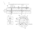
以下、図面を参照して本発明の実施例1を説明する。図1は、実施例1に係る熱処理装置1の概略構成を示す縦断面図である。図2は、熱処理プレート2の平面図である。図3(a)は、実施例1に係る近接部材21、ネジ穴部23およびバネ部材25の構成を示す縦断面図である。図3(b)は、図3(a)の上方から見た近接部材21の平面図である。なお、図1は、図2のA−Aから見た縦断面図である。
図1を参照する。熱処理装置1は、基板Wに対して予め設定された熱処理を行う熱処理プレート2を備えている。熱処理プレート2は、基板Wが載置される方向に設けられた上プレート3と、基板Wが載置される逆方向に設けられた下プレート4と、上プレート3と下プレート4との間に挟まれて配置されたヒータ(加熱機構)5とを備えている。上プレート3および下プレート4は、銅またはアルミニウム等の熱伝導率の高い金属で構成されている。
Please refer to FIG. The
ヒータ5は、例えば抵抗発熱体である金属箔を複数の絶縁フィルムで挟み込んで接着されて形成されているフィルムヒータで構成されている。フィルムヒータは、図示しない電源から供給された電力で加熱される。絶縁フィルムは、例えばポリエステルやポリイミド(PI)の耐熱性を有する樹脂で構成されている。
The
熱処理プレート2は、ヒータ5により、基板Wに対して予め設定された加熱処理を行うが、そのヒータ5に代えて、冷却機構が設けられていてもよい。冷却機構は、例えばペルチェ素子が用いられる。また、熱処理プレート2は、ヒータ5および冷却機構の両方を備えてもよい。
The
また、熱処理装置1は、基板Wを昇降させる3本以上のリフトピン7と、リフトピン7を通す貫通穴8と、リフトピン7を昇降駆動させるため、モータ等で構成された昇降駆動部(図示しない)とを備えている。
Further, the
また、熱処理装置1は、中央演算処理装置(CPU)などで構成された制御部11と、熱処理装置1を操作するための操作部13とを備えている。制御部11は、熱処理装置1の各構成を制御する。操作部13は、液晶モニタなどの表示部と、ROM(Read-only Memory)、RAM(Random-Access Memory)、およびハードディスク等の記憶部と、キーボード、マウス、および各種ボタン等の入力部とを備えている。記憶部には、熱処理条件等が記憶されている。制御部11は、例えば、記憶部に記憶された熱処理条件に基づいて、ヒータ5の加熱およびリフトピン7の昇降を各々制御する。
Further, the
次に、熱処理プレート2(上プレート3)に対して基板Wを近接配置させる構成について説明する。熱処理プレート2の上プレート3は、上述のように、熱伝導率の高い金属で構成される。上プレート3と基板Wとが接触し、基板Wが金属汚染されることを回避するため、基板Wは、近接部材(スペーサともいう)21を介在させて、熱処理プレート2に配置されている。すなわち、基板Wを近接部材21に載置することで、基板W裏面と熱処理プレート2の上面3aとの間の隙間Dを形成し、この隙間Dが形成された状態で、熱処理プレート2による熱処理が行われる。
Next, a configuration in which the substrate W is disposed close to the heat treatment plate 2 (upper plate 3) will be described. As described above, the
図2の平面視において、近接部材21は、3個以上配置されている。なお、図2では3個であるが、例えば、10個または15個設けてもよい。まず、近接部材21が収容されるネジ穴部23について説明する。
In the plan view of FIG. 2, three or
図3(a)を参照する。熱処理プレート2の上プレート3の上面3aには、近接部材21を収容するネジ穴部23が設けられている。ネジ穴部23は、円柱状に掘られて底面を有する。ネジ穴部23の内部側面は、ネジ切りされており、ネジ穴部23は、雌ネジとして機能する。
Reference is made to FIG. On the
一方、近接部材21は、円柱状である。近接部材21の外部側面は、ネジ穴部23のネジ溝23bとかみ合うようにネジ切りされており、近接部材21は、雄ネジとして機能する。そのため、ネジ締めされてネジ穴部23に収容される。なお、符号21bは、近接部材21のネジ部であり、近接部材21は、回転中心C周りに回転されて、ネジが締められたり緩めたりする。
On the other hand, the
また、近接部材21は、耐熱性を有する樹脂で構成される。耐熱性を有する樹脂として、例えば、ポリイミド(PI)、ポリベンゾイミダゾール(PBI)、またはポリエーテルエーテルケトン(PEEK)がある。PIおよびPBIは、最大処理温度が350℃の熱処理プレート2で使用できる。一方、PEEKは、最大処理温度が250℃の熱処理プレート2で使用できる。また、近接部材21は、非金属材料で構成され、近接部材21の樹脂の硬度は、シリコン等の基板Wの硬度よりも小さいこと(近接部材<基板)が好ましい。
The
また、近接部材21の基板Wと接する上面21aは、図3(a)のように、球面状に形成されている。更に、近接部材21は、球面状の上面21aの曲率半径R1がネジ穴部23の半径R2よりも大きくなるように構成されている(R1>R2)。図10の従来の近接部材であるボール121の半径R101は、ボール121が収容されるネジ穴部123の半径R102よりも小さくなるように構成されていた(R101<R102)。本実施例の近接部材21は、ネジ穴部23の半径R2を大きくせずに、近接部材21の球面状の上面21aの曲率半径R1を半径R2よりも大きく設定している。そのため、ネジ穴部23を大きくせずに摩耗量が抑えられる。
Further, the
また、図3(a)、図3(b)のように、近接部材21には、ネジを締めたり緩めたりするための工具の先端を収める工具溝21cが形成されている。なお、工具溝21cを除き、近接部材21の上面21aの略全面は、球面状に形成されている。
Further, as shown in FIGS. 3A and 3B, the
また、ネジ穴部23には、近接部材21と共にバネ部材25が収容されている。バネ部材25は、近接部材21の下から近接部材21を押し上げるものである。すなわち、バネ部材25は、ネジ穴部23に対する近接部材21のネジの締め付け方向Fと逆方向Lに近接部材21を押すものである。バネ部材25は、例えば、金属または、近接部材21のような耐熱性を有する樹脂で構成される。バネ部材25が耐熱性を有する樹脂で構成されると、任意の形状のバネ部材25を形成し易い。
A
本実施例において、バネ部材25は、単一のリング状バネ部材または、ほぼ一巻きの螺旋状バネ部材で構成される。具体的に説明すると、バネ部材25は、例えば、図3の皿バネ25a、または図4のバネ座金25bで構成される。バネ部材25として、単一の皿バネ25aまたは、ほぼ一巻きのバネ座金25bを用いることで、バネ部材25の厚みを抑えることができる。それにより、ネジ穴部23の深さを浅くでき、熱処理プレート2の厚みを薄くすることができる。なお、バネ座金25bは、リングを切断して2つの切断面の位置をリングの中心線に沿ってずらして構成されたものである。
In the present embodiment, the
また、必要に応じて、複数の皿バネ25aまたは複数のバネ座金25bは、ネジ穴部23に重ねて配置させてもよいし、複数のバネ座金25bをつなげて複数回数巻いたようなコイル状バネ部材であってもよい。
Further, if necessary, a plurality of disc springs 25a or a plurality of
図5は、近接部材21およびバネ部材25の取り付け(組立)を説明する図である。ネジ穴部23に、バネ部材25を収容し、続いて、近接部材21を収容する。近接部材21は雄ネジであり、ネジ穴部23は雌ネジであるので、近接部材21は、ネジ穴部23にネジ締めされる。ネジ穴部23に対して近接部材21が目標高さ位置に近づくと、近接部材21は、バネ部材25と接触し、押し付ける。近接部材21を目標高さ位置までネジ締めする。バネ部材25は、近接部材21による締め付けにより弾性変形する。近接部材21の設置後、近接部材21には、バネ部材25の反発力が加わる。これにより、ネジ穴部23のネジ溝23bに近接部材21のネジ部21bが押し付けられて摩擦力が大きくなる。そのため、近接部材21の緩みを抑制できる。
FIG. 5 is a diagram for explaining attachment (assembly) of the
本実施例によれば、基板Wと熱処理プレート2との間に隙間Dを形成する近接部材21は、耐熱性を有する樹脂で構成される。樹脂は硬度が低く、基板W裏面の擦り傷の発生を抑制できる。また、近接部材21の基板Wと接する上面21aは、球面状に形成されており、球面状の上面21aの曲率半径R1は、ネジ穴部23の半径R2よりも大きくなるように構成されている。これにより、近接部材21を樹脂で構成しても、近接部材21の摩耗を抑制できる。そのため、基板Wと熱処理プレート2との間の隙間Dの変動量を小さくでき、メンテナンスの頻度を低減できる。
According to the present embodiment, the
ここで、図6を参照して、近接部材21の摩耗を抑制できる効果について説明する。図6は、近接部材21への基板Wの載置回数に対する基板載置高さを示す図である。なお、基板Wの載置回数(横軸)は、基板Wを昇降させて基板Wを近接部材21に載置した回数である。一方、基板載置高さ(縦軸)は、基板が載置された高さである。すなわち、初期の高さからの変動量が摩耗量ADである。図6において、球面状の上面21aの曲率半径R1が大きい場合と小さい場合の2種類の比較している。載置回数が多くなると、近接部材21が摩耗することで、点接触が面接触になるが、曲率半径R1が小さいと摩耗量ADが大きい一方、曲率半径R1が大きいと、曲率半径R1が小さい場合に比べて摩耗量ADを少なく抑えることができる。例えば、熱処理プレート2と基板Wとの隙間Dと、その隙間Dの許容量(範囲)Pがあるとする。許容量Pよりも摩耗量ADが小さければ(P>AD)、再度の隙間Dの調整が必要とならない。しかしながら、許容量Pよりも摩耗量ADが大きければ(P<AD)、再度の隙間Dの調整が必要となる。
Here, with reference to FIG. 6, the effect which can suppress the abrasion of the
なお、近接部材21が摩耗して、点接触から面接触になるのであれば、初めから近接部材21の上面21aを平面状にすることが考えられる。この場合、平面状の上面21aに基板Wが片当たりすると、例えば片当たりした部分で摩耗し、ゴミの発生を増やしてしまう欠点がある。
In addition, if the
また、熱処理プレート2の上面3aには、内部側面がネジ切りされたネジ穴部23が設けられている。近接部材21は、ネジ穴部23のネジ溝23bとかみ合うように外部側面がネジ切りされており、ネジ締めされてネジ穴部23に収容される。近接部材21には、ネジ穴部23のネジ溝23bとかみ合うようにネジ切りされており、従来の細かな複数の部品を組み合わせずに細かな隙間Dの調整が容易である。そのため、工数を低減できる。
In addition, the
また、熱処理装置1は、ネジ穴部23に収容されて、ネジ穴部23に対する近接部材21のネジの締め付け方向Fと逆方向Lに近接部材21を押すバネ部材25を更に備えている。従来は、熱膨張を加味して強めに締め付ける作業をしていたが、これは、工数を増やす1つの原因となっている。その従来の作業に代えて、バネ部材25をネジ穴部23に収容し、近接部材21のネジの締め付け方向Fと逆方向Lに近接部材21を押すので、ネジがかみ合った部分で摩擦を大きくしてネジ緩みを抑制できる。その結果、更に工数を低減できる。
The
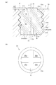
次に、図面を参照して本発明の実施例2を説明する。なお、実施例1と重複する説明は省略する。図7(a)は、実施例2に係る近接部材21、ネジ穴部23および脚バネ部材25cの構成を示す縦断面図である。図7(b)は、図7(a)の下方から見た近接部材21および脚バネ部材25cの下面図である。
Next,
図7(a)を参照する。実施例1では、近接部材21は、バネ部材25と分離して構成されており、2つの部材で構成されていた。この点、本実施例では、近接部材21は、バネ部材25と一体的に構成されている。また、実施例1では、バネ部材25として、例えば皿バネ25aまたはバネ座金25bを用いると説明した。この点、本実施例のバネ部材25は、互いに離れてリング状に配置された複数の脚状の脚バネ部材25cで構成されている。
Reference is made to FIG. In the first embodiment, the
本実施例では、近接部材21は、脚バネ部材25cと一体的に構成されている。すなわち、近接部材21と脚バネ部材25cは一体成形で形成されている。また、脚バネ部材25cは、耐熱性を有する樹脂で構成されている。なお、脚バネ部材25cは、例えば近接部材21と同じ樹脂で構成されていることが好ましいが、脚バネ部材25cは、近接部材21と異なる樹脂であってもよい。
In the present embodiment, the
また、図7(b)のように、脚バネ部材25cは、十字状の切れ込み31により、4つに分岐して構成されている。すなわち、4つの脚バネ部材25cは、互いに離れてリング状に配置されている。近接部材21がネジ締めされると、近接部材21と一体となった脚バネ部材25cが目標位置の前でネジ穴部23の底面と接触する。近接部材21のネジ締めにより脚バネ部材25cが押し込まれると、変形した脚バネ部材25cは切れ込み31に受け入れられる。
Further, as shown in FIG. 7B, the
なお、図7(a)において、脚バネ部材25cは、回転中心Cに沿って延びて形成されるが、図3(a)の皿バネ25aのように、回転中心Cに対して傾斜して延びて形成されてもよい。また、脚バネ部材25cは、4つに限定されず、2つ以上であればよい。また、脚バネ部材25cは、縦横の行列状に配置されていてもよい。また、脚バネ部材25cは、リング状に配置されずに1つであってもよい。
In FIG. 7A, the
本実施例によれば、近接部材21とバネ部材25とが一体的になると、細かな複数の部品の取り扱いが減るので、その結果、工数を低減できる。また、バネ部材25は、リング状に配置された4つの脚バネ部材25cである。これにより、4つの脚バネ部材25cが配置されたリング状でもって、近接部材21を受け止めることができる。また、脚バネ部材25cの個数で反発力を調整できる。
According to the present embodiment, when the
本発明は、上記実施形態に限られることはなく、下記のように変形実施することができる。 The present invention is not limited to the above embodiment, and can be modified as follows.
(1)上述した各実施例の近接部材21およびバネ部材25(皿バネ25a、バネ座金25bまたは脚バネ部材25c)に代えて、図8のような、構成を用いてもよい。すなわち、図8において、近接部材41の下面41dには、バネ部材45の一部を収容する穴部47が設けられている。穴部47に収容されるバネ部材45の先端は、締め付け方向F(または緩める方向L、すなわち回転中心C)に切れ込み49が入って分岐するように構成されている。バネ部材45および穴部47は、締め付け方向Fに対して傾斜した傾斜面45a,47aが形成され、その傾斜面45a,47aを介してバネ部材45と穴部47は接触する。
(1) Instead of the
なお、傾斜面45aは、バネ部材45の外部側面であり、傾斜面47aは、穴部47の内部側面である。すなわち、バネ部材45は、円錐台状または角錐台状に形成され、穴部47も円錐台状または角錐台状に掘られる。また、バネ部材45および穴部47のいずれか一方には、傾斜面45a,47bが形成されてもよい。例えば、バネ部材45に傾斜面45aが形成されていれば、穴部47は、傾斜面47aが形成されていなくてもよい。
The
近接部材41がネジ締めされると、傾斜面45a,47aを介して、近接部材41がバネ部材45に押し付けられる。近接部材41の押し付けにより、バネ部材45の先端が、切れ込み49が狭くなるように変形する。近接部材41を目標高さ位置に配置させると、バネ部材45の先端部の変形などの反発力により、締め付け方向Fと逆方向(緩める方向L)に近接部材41が押される。そのため、ネジ緩みを抑制できる。
When the
本変形例によれば、近接部材41がネジ締めされると、バネ部材45と穴部47は、傾斜面45a、47aを介して接触し、ネジの締め付け力により、バネ部材45の先端部が収容されたバネ部材45の切れ込み49が狭くなるように弾性変形する。その反発力により、近接部材41のネジ緩みを抑制できる。また、近接部材41の下面41dに設けられた穴部47には、バネ部材45の先端部が収容される。そのため、近接部材41とバネ部材45の高さを低く抑えることができ、これにより、ネジ穴部23の深さを浅くでき、熱処理プレート2の厚みを薄くすることができる。
According to this modification, when the
なお、図9のように、構成してもよい。すなわち、穴部47の傾斜面(内部側面)47aには、突起49が設けられている一方、バネ部材45の傾斜面(外周側面)45aには、円筒状に凹ませた案内部53が設けられている。これにより、バネ部材45の先端部を穴部47に収容させると、穴部47にバネ部材45が保持される。すなわち、近接部材41は、バネ部材45と一体的に構成されることになる。なお、突起部51および案内部53により、近接部材41に対してバネ部材45は、予め設定された範囲で回転中心Cにほぼ沿って移動可能である。
It may be configured as shown in FIG. That is, the inclined surface (inner side surface) 47a of the
(2)上述した実施例1では、近接部材21は、バネ部材25と分離して構成されており、2つの部材で構成されていた。この点、近接部材21は、バネ部材25と一体的に構成されてもよい。バネ部材25が金属である場合も含めて、近接部材21とバネ部材25は一体成形で形成してもよい。また、図9のように、保持する機構を設けてもよい。近接部材21とバネ部材25とが一体的になると、細かな複数の部品の取り扱いが減るので、その結果、工数を低減できる。
(2) In Example 1 mentioned above, the
(3)上述した各実施例および各変形例では、近接部材21,41は、耐熱性を有する樹脂のみで構成されていたが、他の材料をの組み合わせでもよい。例えば、基板Wが接する球面状の上面21aが、耐熱性を有する樹脂でコーティングされたものでもよい。この場合、コーティングされる材料は、セラミックや金属などでもよい。コーティングの厚みは、摩耗量等を考慮して設定される。
(3) In each of the above-described embodiments and modifications, the
1 … 熱処理装置
2 … 熱処理プレート
3 … 上プレート
3a … 上面
21,41 … 近接部材
21a … 上面
23 … ネジ穴部
23b … ネジ溝
25,45 … バネ部材
25a … 皿バネ
25b … バネ座金
25c … 脚バネ部材
31,49 … 切れ込み
41d … 下面
45a,47a … 傾斜面
47 … 穴部
D … 隙間
F … 締め付け方向
R1 … 近接部材の球面状の上面の曲率半径
R2 … ネジ穴部の半径
DESCRIPTION OF
Claims (8)
前記熱処理プレートの上面に設けられ、内部側面がネジ切りされたネジ穴部と、
前記ネジ穴部のネジ溝とかみ合うように外部側面がネジ切りされており、ネジ締めされて前記ネジ穴部に収容される近接部材であって、前記基板と前記熱処理プレートとの間に隙間を形成する前記近接部材と、を備え、
前記近接部材は、耐熱性を有する樹脂で構成され、
前記近接部材の前記基板と接する面は、球面状に形成されていると共に、前記球面状の面の曲率半径は、前記ネジ穴部の半径よりも大きくなるように構成されていることを特徴とする熱処理装置。 A heat treatment plate for heat treating the substrate;
A screw hole provided on the upper surface of the heat treatment plate, the inner side surface of which is threaded;
An outer side surface is threaded so as to engage with a screw groove of the screw hole portion, and is a proximity member that is screwed and accommodated in the screw hole portion, and a gap is formed between the substrate and the heat treatment plate. The proximity member to be formed,
The proximity member is made of a heat-resistant resin,
A surface of the proximity member that contacts the substrate is formed in a spherical shape, and a radius of curvature of the spherical surface is configured to be larger than a radius of the screw hole portion. Heat treatment equipment.
前記ネジ穴部に収容されて、前記ネジ穴部に対する前記近接部材のネジの締め付け方向と逆方向に前記近接部材を押すバネ部材を更に備えること熱処理装置。 The heat treatment apparatus according to claim 1,
A heat treatment apparatus, further comprising: a spring member that is accommodated in the screw hole portion and pushes the proximity member in a direction opposite to a tightening direction of a screw of the proximity member with respect to the screw hole portion.
前記近接部材は、前記バネ部材と一体的に構成されていることを特徴とする熱処理装置。 The heat treatment apparatus according to claim 2,
The heat treatment apparatus, wherein the proximity member is integrally formed with the spring member.
前記バネ部材は、耐熱性を有する樹脂で構成されることを特徴とする熱処理装置。 In the heat treatment apparatus according to claim 2 or 3,
The heat treatment apparatus, wherein the spring member is made of heat-resistant resin.
前記バネ部材は、単一のリング状バネ部材であることを特徴とする熱処理装置。 In the heat processing apparatus in any one of Claim 2 to 4,
The heat treatment apparatus, wherein the spring member is a single ring-shaped spring member.
前記バネ部材は、一巻きの螺旋状バネ部材であることを特徴とする熱処理装置。
を特徴とする熱処理装置。 In the heat processing apparatus in any one of Claim 2 to 4,
The heat treatment apparatus according to claim 1, wherein the spring member is a single spiral spring member.
A heat treatment apparatus characterized by
前記バネ部材は、リング状に配置された複数の脚バネ部材であることを特徴とする熱処理装置。 In the heat processing apparatus in any one of Claim 2 to 4,
The heat treatment apparatus, wherein the spring member is a plurality of leg spring members arranged in a ring shape.
前記近接部材の下面には、前記バネ部材の一部を収容する穴部が設けられ、
前記穴部に収容される前記バネ部材の先端は、前記締め付け方向に切れ込みが入って分岐するように構成されており、
前記バネ部材および前記穴部の少なくとも一方は、前記締め付け方向に対して傾斜した傾斜面が形成され、前記傾斜面で前記バネ部材と前記穴部が接触することを特徴とする熱処理装置。 The heat treatment apparatus according to any one of claims 2 to 4, wherein a hole for accommodating a part of the spring member is provided on a lower surface of the proximity member.
The tip of the spring member accommodated in the hole is configured to be branched with a cut in the tightening direction,
At least one of the spring member and the hole is formed with an inclined surface inclined with respect to the tightening direction, and the spring member and the hole are in contact with each other on the inclined surface.
Priority Applications (1)
| Application Number | Priority Date | Filing Date | Title |
|---|---|---|---|
| JP2015120525A JP2017005209A (en) | 2015-06-15 | 2015-06-15 | Heat treatment apparatus |
Applications Claiming Priority (1)
| Application Number | Priority Date | Filing Date | Title |
|---|---|---|---|
| JP2015120525A JP2017005209A (en) | 2015-06-15 | 2015-06-15 | Heat treatment apparatus |
Publications (1)
| Publication Number | Publication Date |
|---|---|
| JP2017005209A true JP2017005209A (en) | 2017-01-05 |
Family
ID=57752289
Family Applications (1)
| Application Number | Title | Priority Date | Filing Date |
|---|---|---|---|
| JP2015120525A Pending JP2017005209A (en) | 2015-06-15 | 2015-06-15 | Heat treatment apparatus |
Country Status (1)
| Country | Link |
|---|---|
| JP (1) | JP2017005209A (en) |
Cited By (2)
| Publication number | Priority date | Publication date | Assignee | Title |
|---|---|---|---|---|
| JP2020533806A (en) * | 2017-09-13 | 2020-11-19 | アプライド マテリアルズ インコーポレイテッドApplied Materials,Incorporated | Board support for reducing damage on the back side of the board |
| JP2023130998A (en) * | 2022-03-08 | 2023-09-21 | 住友電気工業株式会社 | Wafer holder and support pins for wafer holder |
-
2015
- 2015-06-15 JP JP2015120525A patent/JP2017005209A/en active Pending
Cited By (4)
| Publication number | Priority date | Publication date | Assignee | Title |
|---|---|---|---|---|
| JP2020533806A (en) * | 2017-09-13 | 2020-11-19 | アプライド マテリアルズ インコーポレイテッドApplied Materials,Incorporated | Board support for reducing damage on the back side of the board |
| US11955362B2 (en) | 2017-09-13 | 2024-04-09 | Applied Materials, Inc. | Substrate support for reduced damage substrate backside |
| JP2023130998A (en) * | 2022-03-08 | 2023-09-21 | 住友電気工業株式会社 | Wafer holder and support pins for wafer holder |
| JP7800840B2 (en) | 2022-03-08 | 2026-01-16 | 住友電気工業株式会社 | Wafer holder and support pin for wafer holder |
Similar Documents
| Publication | Publication Date | Title |
|---|---|---|
| US8256754B2 (en) | Lift pin for substrate processing | |
| KR100810775B1 (en) | Mounting apparatus | |
| CN1301409C (en) | Method and system for compensating thermal conduction motion of probe card | |
| US7071714B2 (en) | Method and system for compensating for thermally induced motion of probe cards | |
| WO2011158615A1 (en) | Heat dissipation structure for electronic device | |
| CN103065997A (en) | Wafer bearing device and method of wafer bearing | |
| JP2017005209A (en) | Heat treatment apparatus | |
| JP2008221391A (en) | Substrate adsorption fixing mechanism | |
| US20100133256A1 (en) | Stage for substrate temperature control apparatus | |
| JP2019071349A (en) | Heater unit for wafer heating | |
| JP2015088575A (en) | Heat insulation sheet and thermal insulation structure using the same | |
| US20140014643A1 (en) | Heating Device | |
| JP6401638B2 (en) | Heating device | |
| JP6767959B2 (en) | Heat treatment equipment and supporting parts for the material to be treated used for it | |
| TWI495608B (en) | Transfer system | |
| US12069794B2 (en) | Dynamic control of heat sink pressure | |
| JP2017107070A5 (en) | ||
| WO2004049762A1 (en) | Metal heater | |
| CN111911637A (en) | Stop device of electronic expansion valve and mounting method of stop piece | |
| US12176242B2 (en) | Rotatable thermal processing chamber | |
| JP6371721B2 (en) | Wafer polisher | |
| JP2013012509A (en) | Wafer stage for semiconductor manufacturing apparatus, and method of using the same | |
| JP5316769B2 (en) | Flange fastening structure | |
| JP7590131B2 (en) | Polishing Equipment | |
| KR101632191B1 (en) | Power semiconductor module disassembling apparatus |