JP2017005493A - 電子制御装置 - Google Patents
電子制御装置 Download PDFInfo
- Publication number
- JP2017005493A JP2017005493A JP2015117379A JP2015117379A JP2017005493A JP 2017005493 A JP2017005493 A JP 2017005493A JP 2015117379 A JP2015117379 A JP 2015117379A JP 2015117379 A JP2015117379 A JP 2015117379A JP 2017005493 A JP2017005493 A JP 2017005493A
- Authority
- JP
- Japan
- Prior art keywords
- value
- current
- electronic control
- current detection
- control device
- Prior art date
- Legal status (The legal status is an assumption and is not a legal conclusion. Google has not performed a legal analysis and makes no representation as to the accuracy of the status listed.)
- Granted
Links
Images


Classifications
-
- G—PHYSICS
- G06—COMPUTING OR CALCULATING; COUNTING
- G06F—ELECTRIC DIGITAL DATA PROCESSING
- G06F1/00—Details not covered by groups G06F3/00 - G06F13/00 and G06F21/00
- G06F1/26—Power supply means, e.g. regulation thereof
- G06F1/28—Supervision thereof, e.g. detecting power-supply failure by out of limits supervision
-
- F—MECHANICAL ENGINEERING; LIGHTING; HEATING; WEAPONS; BLASTING
- F02—COMBUSTION ENGINES; HOT-GAS OR COMBUSTION-PRODUCT ENGINE PLANTS
- F02D—CONTROLLING COMBUSTION ENGINES
- F02D41/00—Electrical control of supply of combustible mixture or its constituents
- F02D41/20—Output circuits, e.g. for controlling currents in command coils
-
- F—MECHANICAL ENGINEERING; LIGHTING; HEATING; WEAPONS; BLASTING
- F02—COMBUSTION ENGINES; HOT-GAS OR COMBUSTION-PRODUCT ENGINE PLANTS
- F02D—CONTROLLING COMBUSTION ENGINES
- F02D41/00—Electrical control of supply of combustible mixture or its constituents
- F02D41/24—Electrical control of supply of combustible mixture or its constituents characterised by the use of digital means
- F02D41/2406—Electrical control of supply of combustible mixture or its constituents characterised by the use of digital means using essentially read only memories
- F02D41/2425—Particular ways of programming the data
- F02D41/2429—Methods of calibrating or learning
- F02D41/2451—Methods of calibrating or learning characterised by what is learned or calibrated
- F02D41/2464—Characteristics of actuators
- F02D41/2467—Characteristics of actuators for injectors
-
- G—PHYSICS
- G06—COMPUTING OR CALCULATING; COUNTING
- G06F—ELECTRIC DIGITAL DATA PROCESSING
- G06F1/00—Details not covered by groups G06F3/00 - G06F13/00 and G06F21/00
- G06F1/04—Generating or distributing clock signals or signals derived directly therefrom
- G06F1/06—Clock generators producing several clock signals
-
- H—ELECTRICITY
- H03—ELECTRONIC CIRCUITRY
- H03F—AMPLIFIERS
- H03F3/00—Amplifiers with only discharge tubes or only semiconductor devices as amplifying elements
- H03F3/20—Power amplifiers, e.g. Class B amplifiers, Class C amplifiers
- H03F3/21—Power amplifiers, e.g. Class B amplifiers, Class C amplifiers with semiconductor devices only
- H03F3/217—Class D power amplifiers; Switching amplifiers
- H03F3/2171—Class D power amplifiers; Switching amplifiers with field-effect devices
-
- H—ELECTRICITY
- H03—ELECTRONIC CIRCUITRY
- H03K—PULSE TECHNIQUE
- H03K7/00—Modulating pulses with a continuously-variable modulating signal
- H03K7/08—Duration or width modulation ; Duty cycle modulation
-
- F—MECHANICAL ENGINEERING; LIGHTING; HEATING; WEAPONS; BLASTING
- F02—COMBUSTION ENGINES; HOT-GAS OR COMBUSTION-PRODUCT ENGINE PLANTS
- F02D—CONTROLLING COMBUSTION ENGINES
- F02D41/00—Electrical control of supply of combustible mixture or its constituents
- F02D41/20—Output circuits, e.g. for controlling currents in command coils
- F02D2041/202—Output circuits, e.g. for controlling currents in command coils characterised by the control of the circuit
- F02D2041/2024—Output circuits, e.g. for controlling currents in command coils characterised by the control of the circuit the control switching a load after time-on and time-off pulses
- F02D2041/2027—Control of the current by pulse width modulation or duty cycle control
-
- F—MECHANICAL ENGINEERING; LIGHTING; HEATING; WEAPONS; BLASTING
- F02—COMBUSTION ENGINES; HOT-GAS OR COMBUSTION-PRODUCT ENGINE PLANTS
- F02D—CONTROLLING COMBUSTION ENGINES
- F02D41/00—Electrical control of supply of combustible mixture or its constituents
- F02D41/20—Output circuits, e.g. for controlling currents in command coils
- F02D2041/202—Output circuits, e.g. for controlling currents in command coils characterised by the control of the circuit
- F02D2041/2058—Output circuits, e.g. for controlling currents in command coils characterised by the control of the circuit using information of the actual current value
-
- F—MECHANICAL ENGINEERING; LIGHTING; HEATING; WEAPONS; BLASTING
- F02—COMBUSTION ENGINES; HOT-GAS OR COMBUSTION-PRODUCT ENGINE PLANTS
- F02D—CONTROLLING COMBUSTION ENGINES
- F02D41/00—Electrical control of supply of combustible mixture or its constituents
- F02D41/24—Electrical control of supply of combustible mixture or its constituents characterised by the use of digital means
- F02D41/26—Electrical control of supply of combustible mixture or its constituents characterised by the use of digital means using computer, e.g. microprocessor
- F02D41/28—Interface circuits
- F02D2041/286—Interface circuits comprising means for signal processing
-
- F—MECHANICAL ENGINEERING; LIGHTING; HEATING; WEAPONS; BLASTING
- F02—COMBUSTION ENGINES; HOT-GAS OR COMBUSTION-PRODUCT ENGINE PLANTS
- F02D—CONTROLLING COMBUSTION ENGINES
- F02D2250/00—Engine control related to specific problems or objectives
- F02D2250/14—Timing of measurement, e.g. synchronisation of measurements to the engine cycle
-
- H—ELECTRICITY
- H03—ELECTRONIC CIRCUITRY
- H03F—AMPLIFIERS
- H03F2200/00—Indexing scheme relating to amplifiers
- H03F2200/261—Amplifier which being suitable for instrumentation applications
-
- H—ELECTRICITY
- H03—ELECTRONIC CIRCUITRY
- H03F—AMPLIFIERS
- H03F2200/00—Indexing scheme relating to amplifiers
- H03F2200/351—Pulse width modulation being used in an amplifying circuit
-
- H—ELECTRICITY
- H03—ELECTRONIC CIRCUITRY
- H03F—AMPLIFIERS
- H03F2200/00—Indexing scheme relating to amplifiers
- H03F2200/462—Indexing scheme relating to amplifiers the current being sensed
-
- H—ELECTRICITY
- H03—ELECTRONIC CIRCUITRY
- H03F—AMPLIFIERS
- H03F2200/00—Indexing scheme relating to amplifiers
- H03F2200/78—A comparator being used in a controlling circuit of an amplifier
Landscapes
- Engineering & Computer Science (AREA)
- General Engineering & Computer Science (AREA)
- Theoretical Computer Science (AREA)
- Chemical & Material Sciences (AREA)
- Combustion & Propulsion (AREA)
- Mechanical Engineering (AREA)
- Physics & Mathematics (AREA)
- General Physics & Mathematics (AREA)
- Power Engineering (AREA)
- Analogue/Digital Conversion (AREA)
- Electronic Switches (AREA)
Abstract
Description
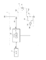
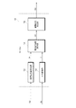
図1に示されるように、本実施形態の電子制御装置1は誘導性負荷2の駆動を制御する。誘導性負荷2は、車両に搭載された変速機用油圧バルブ等、リニアソレノイドLを動力源とする機器である。電子制御装置1は、マイクロコンピュータ10と、半導体スイッチ20と、電流検出部30とを備えている。以下では、電子制御装置1を「ECU(Electronic Control Unit)1」と略記し、マイクロコンピュータ10を「マイコン10」と略記する。本実施形態では、マイコン10が制御部に相当する。
との偏差ΔIを演算する。以下では、電流検出値Iの平均値Iaveを「平均電流値Iave」と略記する。本実施形態では、平均電流値Iaveが電流演算値に相当する。電流値偏差演算部14は、当該電流偏差ΔIを駆動信号生成部15に出力する。
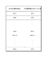
・マイコン10は、取り込み開始時期tsの学習を、デューティ比Dに設定された複数の領域毎に行ってもよい。具体的には、図8に示されるように、デューティ比Dに対して複数の領域を設定する。図8は、デューティ比に設定された複数の領域のうち、3つの領域を例示したものである。3つのデューティ比の領域は、「D1<D≦D2」、「D2<D≦D3」、及び「D3<D≦D4」に設定されている。所定値D1〜D4には、「D1<D2<D3<D4」という関係がある。
Sb:電流検出信号
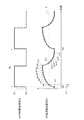
T1:第1サンプリング周期
T2:第2サンプリング周期
1:電子制御装置
2:誘導性負荷
10:マイコン(制御部)
13:A/D変換部
30:電流検出部
Claims (7)
- 誘導性負荷(2)の駆動を制御する電子制御装置(1)であって、
前記誘導性負荷を流れる電流を検出し、検出された電流値に応じた電流検出信号(Sb)をアナログ信号で出力する電流検出部(30)と、
所定の取り込みタイミングで前記電流検出部から前記電流検出信号を取り込み、当該電流検出信号をアナログ信号からデジタル値に変換するA/D変換部(13)と、
前記A/D変換部によりデジタル値に変換された電流検出値に対して所定の演算処理を行うことにより電流演算値を演算し、当該電流演算値に基づいて前記誘導性負荷を流れる電流を制御する制御部(10)と、を備え、
前記取り込みタイミングを変化させつつ前記電流演算値を取得することにより、複数の異なる取り込みタイミングに対する前記電流演算値のサンプル値を取得し、
前記複数の異なる取り込みタイミングに対する前記電流演算値のサンプル値と、前記電流演算値の理想値との偏差を演算し、当該偏差が最小となるように前記A/D変換部の前記取り込みタイミングを学習することを特徴とする電子制御装置。 - 請求項1に記載の電子制御装置において、
前記取り込みタイミングは、前記誘導性負荷の駆動周期のタイミングを取り込み開始時期として、当該取り込み開始時期から所定のサンプリング周期ずつずれた時期として設定されていることを特徴とする電子制御装置。 - 請求項2に記載の電子制御装置において、
前記サンプリング周期として、第1サンプリング周期(T1)と、当該第1サンプリング周期よりも長い第2サンプリング周期(T2)と、を有し、
前記電流演算値の理想値を演算する際には、前記電流検出値のサンプリング周期として、前記第1サンプリング周期を用いるとともに、
前記電流演算値のサンプル値を演算する際、及び前記誘導性負荷の電流制御に用いられる前記電流演算値を演算する際には、前記電流検出値のサンプリング周期として、前記第2サンプリング周期を用いることを特徴とする電子制御装置。 - 請求項1に記載の電子制御装置において、
前記理想値として、前記誘導性負荷を流れる電流の目標値である目標電流値(I*)が用いられていることを特徴とする電子制御装置。 - 請求項1に記載の電子制御装置において、
前記制御部により前記誘導性負荷の電流制御が実行される前に、前記A/D変換部の前記取り込み開始時期の学習を行うことを特徴とする電子制御装置。 - 請求項1に記載の電子制御装置において、
前記制御部は、前記演算処理として、前記電流検出値の平均値を演算する平均化処理を行うことを特徴とする電子制御装置。 - 請求項1に記載の電子制御装置において、
前記制御部は、前記電流演算値を目標電流値に追従させる電流フィードバック制御の実行によりデューティ比を演算するとともに、当該デューティ比に基づいてPWM駆動信号(Sd)を生成し、当該PWM駆動信号に基づいてスイッチング素子の駆動を制御することで前記誘導性負荷を流れる電流をPWM制御するものであり、
前記A/D変換部の前記取り込みタイミングは、前記デューティ比に設定された複数の領域毎に設定されていることを特徴とする電子制御装置。
Priority Applications (2)
| Application Number | Priority Date | Filing Date | Title |
|---|---|---|---|
| JP2015117379A JP6354671B2 (ja) | 2015-06-10 | 2015-06-10 | 電子制御装置 |
| US15/173,776 US9740260B2 (en) | 2015-06-10 | 2016-06-06 | Electronic control apparatus |
Applications Claiming Priority (1)
| Application Number | Priority Date | Filing Date | Title |
|---|---|---|---|
| JP2015117379A JP6354671B2 (ja) | 2015-06-10 | 2015-06-10 | 電子制御装置 |
Publications (2)
| Publication Number | Publication Date |
|---|---|
| JP2017005493A true JP2017005493A (ja) | 2017-01-05 |
| JP6354671B2 JP6354671B2 (ja) | 2018-07-11 |
Family
ID=57517012
Family Applications (1)
| Application Number | Title | Priority Date | Filing Date |
|---|---|---|---|
| JP2015117379A Active JP6354671B2 (ja) | 2015-06-10 | 2015-06-10 | 電子制御装置 |
Country Status (2)
| Country | Link |
|---|---|
| US (1) | US9740260B2 (ja) |
| JP (1) | JP6354671B2 (ja) |
Cited By (1)
| Publication number | Priority date | Publication date | Assignee | Title |
|---|---|---|---|---|
| JP2022034681A (ja) * | 2020-08-19 | 2022-03-04 | 株式会社アイシン | 電流検出装置 |
Families Citing this family (1)
| Publication number | Priority date | Publication date | Assignee | Title |
|---|---|---|---|---|
| CN116841343A (zh) * | 2022-03-25 | 2023-10-03 | 追觅创新科技(苏州)有限公司 | 电子器件的恒功率控制装置、方法、设备及存储介质 |
Citations (9)
| Publication number | Priority date | Publication date | Assignee | Title |
|---|---|---|---|---|
| JPH11308107A (ja) * | 1998-04-21 | 1999-11-05 | Denso Corp | 信号入力装置,制御装置及び誘導性負荷の電流制御装置 |
| JP2004187207A (ja) * | 2002-12-06 | 2004-07-02 | Toyota Motor Corp | A/d変換器制御装置 |
| JP2008182508A (ja) * | 2007-01-25 | 2008-08-07 | Hitachi Ltd | A/d変換装置 |
| JP2008245002A (ja) * | 2007-03-28 | 2008-10-09 | Anritsu Corp | A/d変換装置 |
| JP2011082786A (ja) * | 2009-10-07 | 2011-04-21 | Renesas Electronics Corp | 半導体集積回路及びその制御方法 |
| JP2011223570A (ja) * | 2010-03-25 | 2011-11-04 | Kawasaki Microelectronics Inc | Ad変換回路 |
| WO2013046497A1 (ja) * | 2011-09-30 | 2013-04-04 | 日本電気株式会社 | アナログデジタル変換回路及びアナログデジタル変換方法 |
| JP2013251820A (ja) * | 2012-06-01 | 2013-12-12 | Tdk Corp | 電流測定回路 |
| JP2015062095A (ja) * | 2013-09-23 | 2015-04-02 | 株式会社デンソー | 負荷駆動制御装置 |
Family Cites Families (4)
| Publication number | Priority date | Publication date | Assignee | Title |
|---|---|---|---|---|
| US6687555B1 (en) | 1998-04-21 | 2004-02-03 | Denso Corporation | Linear solenoid control apparatus and method having increased responsiveness features |
| JP4647284B2 (ja) | 2004-11-02 | 2011-03-09 | 富士通セミコンダクター株式会社 | アナログ/デジタル変換方法及びアナログ/デジタル変換回路 |
| JP5978932B2 (ja) | 2012-11-07 | 2016-08-24 | 株式会社デンソー | 誘導性負荷制御装置 |
| JP5803987B2 (ja) * | 2013-06-20 | 2015-11-04 | 株式会社デンソー | 負荷駆動制御装置 |
-
2015
- 2015-06-10 JP JP2015117379A patent/JP6354671B2/ja active Active
-
2016
- 2016-06-06 US US15/173,776 patent/US9740260B2/en active Active
Patent Citations (9)
| Publication number | Priority date | Publication date | Assignee | Title |
|---|---|---|---|---|
| JPH11308107A (ja) * | 1998-04-21 | 1999-11-05 | Denso Corp | 信号入力装置,制御装置及び誘導性負荷の電流制御装置 |
| JP2004187207A (ja) * | 2002-12-06 | 2004-07-02 | Toyota Motor Corp | A/d変換器制御装置 |
| JP2008182508A (ja) * | 2007-01-25 | 2008-08-07 | Hitachi Ltd | A/d変換装置 |
| JP2008245002A (ja) * | 2007-03-28 | 2008-10-09 | Anritsu Corp | A/d変換装置 |
| JP2011082786A (ja) * | 2009-10-07 | 2011-04-21 | Renesas Electronics Corp | 半導体集積回路及びその制御方法 |
| JP2011223570A (ja) * | 2010-03-25 | 2011-11-04 | Kawasaki Microelectronics Inc | Ad変換回路 |
| WO2013046497A1 (ja) * | 2011-09-30 | 2013-04-04 | 日本電気株式会社 | アナログデジタル変換回路及びアナログデジタル変換方法 |
| JP2013251820A (ja) * | 2012-06-01 | 2013-12-12 | Tdk Corp | 電流測定回路 |
| JP2015062095A (ja) * | 2013-09-23 | 2015-04-02 | 株式会社デンソー | 負荷駆動制御装置 |
Cited By (2)
| Publication number | Priority date | Publication date | Assignee | Title |
|---|---|---|---|---|
| JP2022034681A (ja) * | 2020-08-19 | 2022-03-04 | 株式会社アイシン | 電流検出装置 |
| JP7501220B2 (ja) | 2020-08-19 | 2024-06-18 | 株式会社アイシン | 電流検出装置 |
Also Published As
| Publication number | Publication date |
|---|---|
| JP6354671B2 (ja) | 2018-07-11 |
| US20160363981A1 (en) | 2016-12-15 |
| US9740260B2 (en) | 2017-08-22 |
Similar Documents
| Publication | Publication Date | Title |
|---|---|---|
| JP5280332B2 (ja) | 電流制御用半導体素子およびそれを用いた制御装置 | |
| US9705410B2 (en) | Power conversion apparatus | |
| JP2012191821A (ja) | 電流方向検出回路及びdc−dcコンバータ | |
| JP2015089289A (ja) | 電源装置及び電源装置の異常判定方法 | |
| US11005471B2 (en) | Signal generating circuit and power supply device | |
| JP6354671B2 (ja) | 電子制御装置 | |
| TWI509968B (zh) | 電壓轉換電路以及電壓轉換控制器與應用於其中的參數設定方法 | |
| US11742784B2 (en) | Method for determining the error voltage of a current converter and three-phase machine having error voltage compensation | |
| JP2013044668A (ja) | 負荷駆動装置 | |
| JP6148492B2 (ja) | 車両用電源制御装置 | |
| US9035592B2 (en) | Apparatus and method for controlling speed of motor | |
| US20150023071A1 (en) | Voltage converter circuit and voltage converter controller and parameter setting method therefor | |
| JP5915054B2 (ja) | ソレノイドの通電制御装置 | |
| JP6471649B2 (ja) | 電子制御装置 | |
| JP5979165B2 (ja) | 酸素濃度センサの素子インピーダンス検出装置 | |
| JP2002199742A (ja) | Pwm電流制御型誘導負荷ドライバおよびその負荷電流検出方法 | |
| CN111526639A (zh) | 提升恒流Buck电路的输出电流精度的方法及其装置 | |
| JP7484776B2 (ja) | 空燃比センサ制御装置 | |
| US12483109B2 (en) | Current sensing apparatus and control method | |
| JP5983514B2 (ja) | 誘導性負荷駆動装置 | |
| JP7354901B2 (ja) | 空燃比センサ制御装置 | |
| JP4497010B2 (ja) | 電動パワーステアリング制御装置 | |
| JP2019163961A (ja) | 電流検出回路 | |
| US20220153342A1 (en) | Setting device for setting an effective value of an electric load current at a time-variant load | |
| JP2016068744A (ja) | 電動パワーステアリング装置 |
Legal Events
| Date | Code | Title | Description |
|---|---|---|---|
| A621 | Written request for application examination |
Free format text: JAPANESE INTERMEDIATE CODE: A621 Effective date: 20170825 |
|
| A977 | Report on retrieval |
Free format text: JAPANESE INTERMEDIATE CODE: A971007 Effective date: 20180426 |
|
| TRDD | Decision of grant or rejection written | ||
| A01 | Written decision to grant a patent or to grant a registration (utility model) |
Free format text: JAPANESE INTERMEDIATE CODE: A01 Effective date: 20180515 |
|
| A61 | First payment of annual fees (during grant procedure) |
Free format text: JAPANESE INTERMEDIATE CODE: A61 Effective date: 20180528 |
|
| R151 | Written notification of patent or utility model registration |
Ref document number: 6354671 Country of ref document: JP Free format text: JAPANESE INTERMEDIATE CODE: R151 |
|
| R250 | Receipt of annual fees |
Free format text: JAPANESE INTERMEDIATE CODE: R250 |
|
| R250 | Receipt of annual fees |
Free format text: JAPANESE INTERMEDIATE CODE: R250 |
|
| R250 | Receipt of annual fees |
Free format text: JAPANESE INTERMEDIATE CODE: R250 |
|
| R250 | Receipt of annual fees |
Free format text: JAPANESE INTERMEDIATE CODE: R250 |
|
| R250 | Receipt of annual fees |
Free format text: JAPANESE INTERMEDIATE CODE: R250 |