JP2017009012A - Rotary joint - Google Patents
Rotary joint Download PDFInfo
- Publication number
- JP2017009012A JP2017009012A JP2015123935A JP2015123935A JP2017009012A JP 2017009012 A JP2017009012 A JP 2017009012A JP 2015123935 A JP2015123935 A JP 2015123935A JP 2015123935 A JP2015123935 A JP 2015123935A JP 2017009012 A JP2017009012 A JP 2017009012A
- Authority
- JP
- Japan
- Prior art keywords
- fixed
- rotary joint
- step portion
- rotating
- rotation
- Prior art date
- Legal status (The legal status is an assumption and is not a legal conclusion. Google has not performed a legal analysis and makes no representation as to the accuracy of the status listed.)
- Granted
Links
Images




Landscapes
- Joints Allowing Movement (AREA)
Abstract
【課題】回転中心方向に関する寸法を短くでき、小型化を実現できるロータリージョイントを提供する。
【解決手段】固定体20と、固定体に対し、回転中心の回りを相対回転可能に装着される回転体10と、固定体と回転体とにより規定される一方及び他方の環状封止空間S1、S2、S3に配置される一方及び他方の封止部材R1,R2,R3と、一方及び他方の環状封止空間を連通する連絡路P1、P2と、を備え、一方の環状封止空間と、他方の環状封止空間とは、回転中心からの距離が異なるロータリージョイント。
【選択図】図3Provided is a rotary joint that can be reduced in size with respect to the rotation center direction and can be reduced in size.
SOLUTION: A fixed body 20, a rotating body 10 mounted so as to be relatively rotatable around a rotation center with respect to the fixed body, and one and the other annular sealed spaces S1 defined by the fixed body and the rotating body. , S2 and S3, and one and the other sealing members R1, R2, and R3, and communication paths P1 and P2 communicating the one and the other annular sealing spaces, and one annular sealing space and A rotary joint with a different distance from the center of rotation is different from the other annular sealed space.
[Selection] Figure 3
Description
本発明は、半導体製造装置、菓子製造装置等の産業用ロボットにおいて相対回転部材間で流体を供給するためのロータリージョイントに関する。 The present invention relates to a rotary joint for supplying a fluid between relative rotating members in an industrial robot such as a semiconductor manufacturing apparatus or a confectionery manufacturing apparatus.
従来より、種々のロータリージョイントが提案されている。例えば、特許文献1は、複数の異種流体を混在させることなく、各別ルートで相対回転部材間において流動させるためのロータリージョイントを開示する。このロータリージョイントでは、ジョイント本体、すなわち固定体の内周面と回転体の外周面との間には、環状空間が設けられ、また環状空間には互いに閉塞する複数の連絡空間が形成されている。固定体は、その径方向に延在する第2の流体路が設けられている流体路形成部材を備える。さらに、回転体は、回転中心方向に延在する第1の流体路が設けられている。
Conventionally, various rotary joints have been proposed. For example,
流体は、第2の流体路からロータリージョイント内へ進入し、環状空間に設けられている連絡空間を通り、回転体に設けられている第1の流体路へと流動する。 The fluid enters the rotary joint from the second fluid path, flows through the communication space provided in the annular space, and flows to the first fluid path provided in the rotating body.
上記流体路形成部材には、第2の流体路を規定する流路用溝と、回転中心方向に関し流路用溝から離間し、連絡空間を封止するための一対のOリング用の溝が形成されている。このように、固定体に装着される流体路形成部材には、第2の流体路を規定する壁部、さらに、一対のOリングがそれぞれ配置される凹状部を規定する壁部が延在する構成である。 The fluid path forming member includes a channel groove that defines the second fluid path and a pair of O-ring grooves that are spaced apart from the channel groove with respect to the rotation center direction and seal the communication space. Is formed. As described above, the fluid path forming member attached to the fixed body extends the wall section that defines the second fluid path and the wall section that defines the recessed section in which the pair of O-rings are respectively disposed. It is a configuration.
また、ロータリージョイントには、例えば特許文献2に示すような構成も存在している。特許文献2は、互いに相対回転可能な固定体及び回転軸間で複数種類の流体を授受するためのロータリージョイントを開示する。このロータリージョイントは、回転軸に対し装着される外筒が、複数の外筒ユニットから構成されている。
Moreover, the structure as shown, for example in
外筒ユニットは、内側スリーブと、内側スリーブに対し相対回転可能にベアリングを介し外嵌される固定筒体とを備え、当該内側スリーブは、回転軸に対し固定される。流体の種類毎に形成される上記構成の外筒ユニットが単一の回転軸の外周面に嵌合される構成である。 The outer cylinder unit includes an inner sleeve and a fixed cylinder body fitted through a bearing so as to be rotatable relative to the inner sleeve, and the inner sleeve is fixed to the rotation shaft. The outer cylinder unit of the said structure formed for every kind of fluid is a structure fitted by the outer peripheral surface of a single rotating shaft.
固定体側からの流体は、固定筒体に設けられている、外部ポート及び外部ポートに連通する送通流体用流路と、内側スリーブに設けられている、溝部及び孔とを通り、回転軸側に設けられる対応流路へ供給される。 The fluid from the fixed body side passes through the external port and the flow path for fluid to be communicated with the external port provided in the fixed cylinder and the groove and the hole provided in the inner sleeve, and is on the rotating shaft side. To the corresponding flow path provided in
特許文献1のロータリージョイントは、上記の通り、第2の流体路を規定する壁部と、一対のOリング用の凹状部を規定する壁部とを備える構成であるため、ロータリージョイントの小型化、特に回転中心方向に関する寸法を小さくすることが難しい。
As described above, the rotary joint of
また、特許文献2のロータリージョイントでは、上記の通り、流体の種類毎に用意される外筒ユニットが単一の回転軸に嵌合され、複数種類の流体を固定体と回転軸間で授受する構成である。従って、ロータリージョイントを通る流体の数を変更する際には、当該流体の数に対応する数の流路を備える回転軸を用意する必要が生じ、ロータリージョイントの汎用性を高めることが難しい。
Moreover, in the rotary joint of
本発明は、かかる事情に鑑みてなされたものである。すなわち、回転中心方向に関する寸法を短くでき、小型化を実現できるロータリージョイントを提供することを目的とする。
また、相対回転する回転体及び固定体間で授受される流体の数に変更があっても対応できるロータリージョイントを提供することが好ましい。
The present invention has been made in view of such circumstances. That is, it aims at providing the rotary joint which can shorten the dimension regarding a rotation center direction and can implement | achieve size reduction.
It is also preferable to provide a rotary joint that can cope with changes in the number of fluids exchanged between a rotating body and a stationary body that rotate relative to each other.
上述した課題を解決し、目的を達成するために、本発明のロータリージョイントの第1の態様は、固定体と、固定体に対し、回転中心の回りを相対回転可能に装着される回転体と、固定体と回転体とにより規定される一方及び他方の環状封止空間に配置される一方及び他方の封止部材と、一方及び他方の環状封止空間を連通する連絡路と、を備え、一方の環状封止空間と、他方の環状封止空間とは、回転中心からの距離が異なる、ことを特徴としている。 In order to solve the above-described problems and achieve the object, a first aspect of the rotary joint of the present invention includes a fixed body, and a rotating body that is attached to the fixed body so as to be relatively rotatable around a rotation center. One and the other sealing members arranged in one and the other annular sealing space defined by the fixed body and the rotating body, and a communication path communicating the one and the other annular sealing space, One annular sealing space and the other annular sealing space are characterized in that the distance from the rotation center is different.
また、本発明の他の態様は、上述の発明において、固定体には一方の固定段部と他方の固定段部が設けられ、一方の固定段部と他方の固定段部とは、回転中心からの距離が異なっていて、回転体には一方の回転段部と他方の回転段部が設けられ、一方の回転段部と他方の回転段部とは、回転中心からの距離が異なっていて、一方の固定段部に対して一方の回転段部が対向することで一方の環状封止空間が形成され、他方の固定段部に対して他方の回転段部が対向することで他方の環状封止空間が形成される、ことが好ましい。 According to another aspect of the present invention, in the above-described invention, the fixed body is provided with one fixed step portion and the other fixed step portion, and the one fixed step portion and the other fixed step portion have a rotation center. The rotating body is provided with one rotating step portion and the other rotating step portion, and the one rotating step portion and the other rotating step portion have different distances from the rotation center. One annular step space is formed by one rotating step portion facing one fixed step portion, and the other annular step space is formed by the other rotating step portion facing the other fixed step portion. It is preferable that a sealed space is formed.
また、本発明の他の態様は、上述の発明において、一方の環状封止空間を構成する一方の固定円筒面と、他方の環状封止空間を構成する他方の回転円筒面とによって、連絡路が規定される、ことが好ましい。 Further, according to another aspect of the present invention, in the above-described invention, a communication path is formed by one fixed cylindrical surface constituting one annular sealed space and the other rotating cylindrical surface constituting the other annular sealed space. Is preferably defined.
また、本発明の他の態様は、上述の発明において、連絡路の径方向寸法は、一方の封止部材の断面の内径寸法と外径寸法の範囲内としている、ことが好ましい。 In another aspect of the present invention, in the above-described invention, it is preferable that the radial dimension of the communication path is within the range of the inner diameter dimension and the outer diameter dimension of the cross section of one sealing member.
また、本発明の他の態様は、上述の発明において、回転体は、回転中心が延びる方向に貫通する貫通孔を備える、ことが好ましい。 In another aspect of the present invention, in the above-described invention, it is preferable that the rotating body includes a through-hole penetrating in a direction in which the rotation center extends.
また、本発明の他の態様は、上述の発明において、回転体に装着され連絡路に連通する流体管を備え、流体管が貫通孔内に延在する、ことが好ましい。 In another aspect of the present invention, in the above-described invention, it is preferable that the fluid pipe is attached to the rotating body and communicated with the communication path, and the fluid pipe extends into the through hole.
また、本発明の他の態様は、上述の発明において、上述した発明のロータリージョイントを複数と、複数のロータリージョイントを互いに接続するための締結手段と、を備え、複数のロータリージョイントの内の一のロータリージョイントの回転体に装着される流体管が、一のロータリージョイントの貫通孔と、複数のロータリージョイントの内の他のロータリージョイントの貫通孔とに挿通されている、ことが好ましい。 According to another aspect of the present invention, in the above-described invention, the rotary joint according to the above-described invention includes a plurality of rotary joints and fastening means for connecting the plurality of rotary joints to each other. It is preferable that the fluid pipe attached to the rotary body of the rotary joint is inserted into the through hole of one rotary joint and the through holes of the other rotary joints among the plurality of rotary joints.
なお、本明細書において、正圧とは大気圧よりも高い圧力を意味し、負圧とは大気圧よりも低い圧力を意味し、流体とは、気体又は液体を意味する。 In the present specification, positive pressure means pressure higher than atmospheric pressure, negative pressure means pressure lower than atmospheric pressure, and fluid means gas or liquid.
本発明に係るロータリージョイントによれば、回転中心方向に関する寸法を短くでき、それによって小型化を実現することが可能となる。 According to the rotary joint according to the present invention, it is possible to shorten the dimension with respect to the rotation center direction, thereby realizing miniaturization.
以下に、本発明の実施形態に係るロータリージョイントについて図面を参照しつつ説明する。なお、この実施形態によりこの発明が限定されるものではない。 Hereinafter, a rotary joint according to an embodiment of the present invention will be described with reference to the drawings. In addition, this invention is not limited by this embodiment.
〔第1の実施形態〕
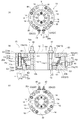
図1(a)は、第1の実施形態に係るロータリージョイント1を示す平面図であり、図1(b)は、第1の実施形態に係るロータリージョイント1を示す正面図であり、図1(c)は、図1(a)の裏面図であり、図2は、図1(a)の線II−IIに沿った断面図であり、図3は、図2のIII部を示す拡大断面図である。
[First Embodiment]
1A is a plan view showing the
第1の実施形態に係るロータリージョイント1は、主として、回転体10と、固定体20と、OリングR1〜R6と、を主要な構成要素としている。また、回転体10は、固定体20に対して相対回転可能に装着されている。また、ロータリージョイント1は、固定体と回転体とにより規定される一方及び他方の環状封止空間に配置される一方及び他方の封止部材であるOリングと、一方及び他方の環状封止空間を連通する連絡路と、を備え、一方の環状封止空間と、他方の環状封止空間とは、回転中心からの距離が異なる。以下に実施形態に係るロータリージョイント1の各構成要素について詳述する。
The
〔回転体〕
回転体10は円筒形状を呈し、その上面10aには吐出路11の一端側が開口している。吐出路11は、回転体10の軸方向に沿って当該回転体10を貫くように形成されていて、その吐出路11の他端側は下面10bで開口している。また、図2に示すように、吐出路11の一端側および他端側には、それぞれネジ孔部111,112が設けられている。それらのうちネジ孔部111には、ホース継手30のネジ部31が捻じ込まれている。
〔Rotating body〕
The rotating
なお、図1(a)に示す構成では、吐出路11は回転体10の周方向に等間隔に4つ設けられていて、それらの吐出路11に、部品締結用のネジ孔14が設けられている。そして、それら4つの吐出路11に、ホース継手30が取り付けられている。しかしながら、吐出路11の個数、およびホース継手30を取り付ける個数は、特に限定されるものではない。なお、以下の説明では、ホース継手30が取り付けられている吐出路11について、区別する必要がある場合には、第1の吐出路11a、第2の吐出路11b、第3の吐出路11c、第4の吐出路11dと称呼する。
In the configuration shown in FIG. 1A, four
また、吐出路11は回転体10の周方向に等間隔に設けられる構成を採用しなくても良い。また、ホース継手30、及び後述するホース継手40は、ロータリージョイント1の構成要素に含めても良いが、ロータリージョイント1の構成要素に含めなくても良い。
Further, the
また、回転体10の内周面10c側には、ロータリージョイント1が装着される不図示の回転機構が装着できる構成となっている。すなわち、図2に示されるように、回転体10の内周面10cは、当該回転体10を軸方向に貫く貫通孔12を画成する。貫通孔12は、吐出路11よりも径方向の中心側に位置している。また、回転体10は、ロータリージョイント1の半径方向(図2の左右方向)に延在する分岐路13を備える。以下の説明では、分岐路13について、区別する必要がある場合には、第1の分岐路13a、第2の分岐路13b、第3の分岐路13c、および第4の分岐路13dと称呼する。これら第1〜第4の分岐路13a〜13dは、その一端部が、それぞれ第1〜第4の吐出路11a〜11dに接続し、その他端部は、回転体10の外周面で開口している。
In addition, a rotation mechanism (not shown) to which the
なお、分岐路13は、吐出路11の個数に対応させて、4つ設けられている。なお、分岐路13の個数は、ポート数に対応させて、回転体10に必要な個数分だけ穿設すれば良い。また、分岐路13の個数は、ポート数よりも多く設けても良く、その場合には、使用していない分岐路13を別途の閉塞部材で閉塞するようにしても良い。
Four
また、図2に示すように、回転体10の外周面は、軸方向の中心線Lを含むような断面視で左右対称の階段形状を呈し、その軸方向の中心線Lにおける中央側の径寸法が大きいが、上面10a及び下面10bに向かい段階的に小さく寸法付けされている。図2においては、回転体10の上面10aと下面10bとの中点を通る直径方向に関し、回転体10の外周断面は、上下対称であるので、図3に示す回転体10の下方に位置する3つの回転段部D1,D2,D3を用いて以下に構成を説明する。
Further, as shown in FIG. 2, the outer peripheral surface of the
図3に示されるように、第1の回転段部D1は、軸方向に延在する第1の回転円筒面D1aと、第1の回転円筒面D1aに接続し、径方向に延在する第1の回転環状面D1bとにより構成されている。同様に、第2の回転段部D2は、軸方向に延在する第2の回転円筒面D2aと、第2の回転円筒面D2aに接続し、径方向に延在する第2の回転環状面D2bとにより構成されている。さらに、第3の回転段部D3は、軸方向に延在する第3の回転円筒面D3aと、第3の回転円筒面D3aに接続し、径方向に延在する第3の回転環状面D3bとにより構成されている。 As shown in FIG. 3, the first rotating step portion D1 is connected to the first rotating cylindrical surface D1a extending in the axial direction and the first rotating cylindrical surface D1a and extends in the radial direction. 1 rotation annular surface D1b. Similarly, the second rotating step portion D2 includes a second rotating cylindrical surface D2a extending in the axial direction and a second rotating annular surface connecting to the second rotating cylindrical surface D2a and extending in the radial direction. D2b. Further, the third rotating step portion D3 is connected to the third rotating cylindrical surface D3a extending in the axial direction, and the third rotating annular surface D3b extending in the radial direction, connected to the third rotating cylindrical surface D3a. It is comprised by.
また、第1の回転段部D1を構成する第1の回転環状面D1bと、第2の回転段部D2を構成する第2の回転円筒面D2aとが接続し、第2の回転段部D2を構成する第2の回転環状面D2bと、第3の回転段部D3を構成する第3の回転円筒面D3aとが接続している。また、第1の回転円筒面D1aの中心線Lに関する曲率半径は、第2の回転円筒面D2aの中心線Lに関する曲率半径より小さく寸法付けされ、第2の回転円筒面D2aの中心線Lに関する曲率半径は、第3の回転円筒面D3aの中心線Lに関する曲率半径より小さく寸法付けされている。 Further, the first rotating annular surface D1b constituting the first rotating step portion D1 and the second rotating cylindrical surface D2a constituting the second rotating step portion D2 are connected, and the second rotating step portion D2 is connected. Are connected to the third rotating annular surface D2b that constitutes the third rotating step portion D3. Further, the radius of curvature with respect to the center line L of the first rotating cylindrical surface D1a is dimensioned smaller than the radius of curvature with respect to the center line L of the second rotating cylindrical surface D2a, and is related to the center line L of the second rotating cylindrical surface D2a. The radius of curvature is dimensioned smaller than the radius of curvature with respect to the center line L of the third rotating cylindrical surface D3a.
なお、図2から明らかなように、回転体10の上方側にも、3つの回転段部D4,D5,D6が設けられている。第4の回転段部D4は、第3の回転段部D3と上下対称であり、第4の回転円筒面D4aと第4の回転環状面D4bとを有している。また、第5の回転段部D5は、第2の回転段部D2と上下対称であり、第5の回転円筒面D5aと第5の回転環状面D5bとを有している。また、第6の回転段部D6は、第1の回転段部D1と上下対称であり、第6の回転円筒面D6aと第6の回転環状面D6bとを有している。なお、これらは上下対称であるため、それらの詳細についての説明は省略する。
As is clear from FIG. 2, three rotation step portions D4, D5, and D6 are also provided on the upper side of the
さらに、図3に示される通り、第2の回転円筒面D2aには、第1の分岐路13aが開口している。なお、図3では、図2の右側下方の部位について説明したが、図2の右側上方の部位も、右側下方の部位と分岐路13を除き同じ構成である。すなわち、軸方向に関し第3の回転段部D3の上方に位置する第4の回転段部D4、第5の回転段部D5および第6の回転段部D6は、それぞれ、第1の回転段部D1、第2の回転段部D2および第3の回転段部D3と、中心線Lからの距離(外径寸法)が同じである。このように、図2の右側上方の部位と右側下方の部位は、回転体10の上面10a及び下面10b間の中点を通る直径に関し上下対称の構成である。
Further, as shown in FIG. 3, a
また、第1の分岐路13aが半径方向に延在しているが、その第1の分岐路13aの外径側は第2の回転段部D2(第2の回転円筒面D2a)で開口する一方、内径側は第1の吐出路11aに連通する。また、第2の分岐路13bの外径側は、第3の回転段部D3(第3の回転円筒面D3a)で開口すると共に、その内径側は第2の吐出路11bに連通する。また、第3の分岐路13cの外径側は、第4の回転段部D4で開口すると共に、その内径側は第3の吐出路11cに連通する。また、第4の分岐路13dの外径側は、第5の回転段部D5で開口すると共に、その内径側は第4の吐出路11dに連通する。
In addition, the
〔固定体〕
図1に示されるように、上述の回転体10は、固定体20の内筒側に相対回転可能となるように転がり軸受B1,B2(図2、図3参照)を介して同心に装着されている。固定体20の外周面20aには、半径方向に直交する面である平面領域21が設けられていて、その平面領域21は、外周面20aを接線方向に切り欠くことで形成されている。また、固定体20を内筒側から外周側に向かって供給路22が貫いており、その供給路22の外周側の端部は、平面領域21で開口している。しかしながら、供給路22の外周側には、それぞれネジ孔部221が設けられている。このネジ孔部221には、ホース継手40のネジ部41が捻じ込み可能となっている。なお、以下の説明では、供給路22について、区別する必要がある場合には、第1の供給路22a、第2の供給路22b、第3の供給路22c、および第4の供給路22dと称呼する。
[Fixed body]
As shown in FIG. 1, the above-described
ここで、平面領域21においては、4つの供給路22は軸方向で同一直線上には配置されないが、供給路22は異なる2つの軸方向に沿う直線上に、2つずつ配置されている。しかも、第1の供給路22aは一方の直線上、第2の供給路22bは別の直線上となるように、供給路22は下面10bから上面10aに向かうにつれて交互に異なる直線上に配置されている。
Here, in the
図2に示されるように、固定体20は、上方固定半片20Aと、下方固定半片20Bとを有している。なお、上方固定半片20A及び下方固定半片20Bの形状は、供給路22の構成等を除き、同じであるので、下方固定半片20Bを主として参照しつつその構成について説明する。
As shown in FIG. 2, the fixed
固定体20の下方固定半片20Bの内周面は、前述の回転体10の外周面と同様に、軸方向の中心線Lを含むような断面視で左右対称な階段形状を呈し、その内周面の径方向の寸法(径寸法)は、上面20B1の径寸法が大きく、下面20B2側に向かうにつれて段階的に小さく寸法付けされている。当該内周面は、第1の固定段部F1、第2の固定段部F2、第3の固定段部F3を有する。図3に示されるように、第1の固定段部F1は、軸方向に延在する第1の固定円筒面F1aと、第1の固定円筒面F1aに接続し、径方向に延在する第1の固定環状面F1bとにより構成されている。同様に、第2の固定段部F2は、軸方向に延在する第2の固定円筒面F2aと、第2の固定円筒面F2aに接続し、径方向に延在する第2の固定環状面F2bとにより構成されている。さらに、第3の固定段部F3は、軸方向に延在する第3の固定円筒面F3aと、第3の固定円筒面F3aに接続し、径方向に延在する第3の固定環状面F3bとにより構成されている。
The inner peripheral surface of the lower fixed
また、第1の固定段部F1を構成する第1の固定円筒面F1aは、第2の固定段部F2を構成する第2の固定環状面F2bに接続し、第2の固定段部F2を構成する第2の固定円筒面F2aは、第3の固定段部F3を構成する第3の固定環状面F3bに接続している。また、第1の固定円筒面F1aの中心線Lに関する曲率半径は、第2の固定円筒面F2aの中心線Lに関する曲率半径より小さく寸法付けされ、第2の固定円筒面F2aの中心線Lに関する曲率半径は、第3の固定円筒面F3aの中心線Lに関する曲率半径より小さく寸法付けされている。 Further, the first fixed cylindrical surface F1a constituting the first fixed step portion F1 is connected to the second fixed annular surface F2b constituting the second fixed step portion F2, and the second fixed step portion F2 is connected to the second fixed step portion F2. The 2nd fixed cylindrical surface F2a to comprise is connected to the 3rd stationary annular surface F3b which comprises the 3rd stationary step part F3. Further, the radius of curvature with respect to the center line L of the first fixed cylindrical surface F1a is dimensioned smaller than the radius of curvature with respect to the center line L of the second fixed cylindrical surface F2a, and is related to the center line L of the second fixed cylindrical surface F2a. The radius of curvature is dimensioned smaller than the radius of curvature with respect to the center line L of the third fixed cylindrical surface F3a.
また、図3に示される通り、第1の供給路22aは平面領域21に直交する方向に延在し、その内周端部は、第1の固定円筒面F1aで開口している。同様に、第2の供給路22bは径方向に延在し、その内周端部は、第2の固定段部F2を構成する第2の固定円筒面F2aで開口している。
In addition, as shown in FIG. 3, the
なお、図2から明らかなように、上方固定半片20Aにおいても、上述の下方固定半片20Bと同様に、3つの固定段部F4,F5,F6が設けられている。第4の固定段部F4は、第3の固定段部F3と上下対称であり、第4の固定円筒面F4aと第4の固定環状面F4bとを有している。また、第5の固定段部F5は、第2の固定段部F2と上下対称であり、第5の固定円筒面F5aと第5の固定環状面F5bとを有している。また、第6の固定段部F6は、第1の固定段部F1と上下対称であり、第6の固定円筒面F6aと第6の固定環状面F6bとを有している。なお、これらは上下対称であるため、それらの詳細についての説明は省略する。
As is apparent from FIG. 2, the upper fixed
また、上方固定半片20Aにおいても、上述の下方固定半片20Bと同様に、第3の供給路22cと第4の供給路22dとが設けられている。しかしながら、これらは、上述の下方固定半片20Bの場合と同様であるため、その詳細についての説明は省略する。
The upper fixed
上記構成の回転体10と固定体20とが互いに相対回転可能に転がり軸受B1,B2を介して固定された状態では、第1の回転段部D1と第1の固定段部F1とにより規定される、断面視が略四角形状の第1の環状封止空間S1に第1のOリングR1が配置される。さらに、第2の回転段部D2と第2の固定段部F2とにより規定される、断面視が略四角形状の第2の環状封止空間S2に第2のOリングR2が収容される。同様に、第3のOリングR3は、第3の回転段部D3と第3の固定段部F3とにより規定される、断面視が略四角形状の第3の環状封止空間S3に収容される。
In a state where the rotating
なお、上方固定半片20A側においても、上述の下方固定半片20Bと同様に、第4の環状封止空間S4と、第5の環状封止空間S5と、第6の環状封止空間S6とが設けられている。これらのうち、第4の環状封止空間S4は、第3の環状封止空間S3と上下対称であり、第4の回転段部D4と第4の固定段部F4により規定され、その内部に第4のOリングR4が収納されている。また、第5の環状封止空間S5は、第2の環状封止空間S2と上下対称であり、第5の回転段部D5と第5の固定段部F5により規定され、その内部に第5のOリングR5が収納されている。また、第6の環状封止空間S6は、第1の環状封止空間S1と上下対称であり、第6の回転段部D6と第6の固定段部F6により規定され、その内部に第6のOリングR6が収納されている。なお、これらは上下対称であるため、それらの詳細についての説明は省略する。
Note that, on the upper fixed
また、第2の回転段部D2の第2の回転円筒面D2aの曲率半径は、第1の固定段部F1の第1の固定円筒面F1aの曲率半径より小さく寸法づけられている。これら第2の回転円筒面D2aの下面10b側と、第1の固定円筒面F1aの上面10a側とは近接対向している。以下、この近接対向部分を、第1の連絡路P1と称呼する。第1の連絡路P1を流れる流体は、第1のOリングR1及び第2のOリングR2により流れが規制される。従って、ホース継手40から進入する流体は、第1の供給路22a、第1の連絡路P1、第1の分岐路13a、及び第1の吐出路11aを介し、ホース継手30から不図示の回転機構へ供給される。
Further, the radius of curvature of the second rotating cylindrical surface D2a of the second rotating step portion D2 is sized smaller than the radius of curvature of the first fixed cylindrical surface F1a of the first fixed step portion F1. The
また、上記の構成のとおり、第1の連絡路P1の外周面は、第1の固定円筒面F1aにより構成される。そして、第1の連絡路P1の内周面を、第2の回転円筒面D2aにより構成し、第2の回転円筒面D2aの曲率半径を、第1のOリングR1の断面の内径寸法と外径寸法の範囲内としている。すなわち、第2の回転円筒面D2aを図3の断面視において第1のOリングR1の内周面の曲率半径より大きく外周面の曲率半径より小さくなるように寸法付けする。このように構成することにより、例えば、2つのOリングR1,R2間に流路を設けることができるが、その際に、第2の回転円筒面D2aに流路としての溝を形成する必要がない。したがって、ロータリージョイント1の軸方向寸法の小型化を実現できる。 Further, as described above, the outer peripheral surface of the first communication path P1 is configured by the first fixed cylindrical surface F1a. Then, the inner peripheral surface of the first communication path P1 is configured by the second rotating cylindrical surface D2a, and the curvature radius of the second rotating cylindrical surface D2a is set to be equal to the inner diameter dimension of the cross section of the first O-ring R1. The diameter is within the range. That is, the second rotating cylindrical surface D2a is dimensioned so as to be larger than the curvature radius of the inner peripheral surface of the first O-ring R1 and smaller than the curvature radius of the outer peripheral surface in the cross-sectional view of FIG. With this configuration, for example, a flow path can be provided between the two O-rings R1 and R2, but in this case, it is necessary to form a groove as a flow path on the second rotating cylindrical surface D2a. Absent. Therefore, the axial dimension of the rotary joint 1 can be reduced.
同様に、その他の連絡路P(第2の連絡路P2,第3の連絡路P3,第4の連絡路P4)は、2つのOリングと、径方向に対面する固定円筒面及び回転円筒面とにより構成される。そして、ホース継手40から第2の供給路22bへと導入される流体は、第2の連絡路P2、及び第2の分岐路13bを介して、第2の吐出路11bから回転体10に装着されている回転機構に供給される。同様に、ホース継手40から第3の供給路22cへと導入される流体は、第3の連絡路P3、及び第3の分岐路13cを介して、第3の吐出路11cから回転体10に装着されている回転機構に供給される。また、ホース継手40から第4の供給路22dへと導入される流体は、第4の連絡路P4、及び第4の分岐路13dを介して、第4の吐出路11dから回転体10に装着されている回転機構に供給される。さらに、各連絡路P(P1〜P4)の内周面及び外周面と、関連するOリングR1〜R6とは、上述の寸法関係を有する。
Similarly, the other connecting path P (second connecting path P2, third connecting path P3, fourth connecting path P4) includes two O-rings, a fixed cylindrical surface and a rotating cylindrical surface facing each other in the radial direction. It consists of. The fluid introduced from the hose joint 40 to the
なお、第1の環状封止空間S1は一方の環状封止空間に対応し、第2の環状封止空間S2は他方の環状封止空間に対応する。このとき、第1の連絡路P1は、連絡路に対応し、第1のOリングR1は一方の封止部材に対応し、第2のOリングR2は、他方の封止部材に対応する。また、第1の回転段部D1は一方の回転段部に対応し、第2の回転段部D2は他方の回転段部に対応し、第1の固定段部F1は一方の固定段部に対応し、第2の固定段部F2は他方の固定段部に対応する。 The first annular sealing space S1 corresponds to one annular sealing space, and the second annular sealing space S2 corresponds to the other annular sealing space. At this time, the first communication path P1 corresponds to the communication path, the first O-ring R1 corresponds to one sealing member, and the second O-ring R2 corresponds to the other sealing member. The first rotation stage D1 corresponds to one rotation stage, the second rotation stage D2 corresponds to the other rotation stage, and the first fixed stage F1 corresponds to one fixed stage. Correspondingly, the second fixed step portion F2 corresponds to the other fixed step portion.
しかしながら、これとは逆に、第1の環状封止空間S1が他方の環状封止空間に対応し、第2の環状封止空間S2が一方の環状封止空間に対応するものとしても良い。このとき、第1のOリングR1は他方の封止部材に対応し、第2のOリングR2は、一方の封止部材に対応する。また、第1の回転段部D1は他方の回転段部に対応し、第2の回転段部D2は一方の回転段部に対応し、第1の固定段部F1は他方の固定段部に対応し、第2の固定段部F2は一方の固定段部に対応する。 However, on the contrary, the first annular sealing space S1 may correspond to the other annular sealing space, and the second annular sealing space S2 may correspond to the one annular sealing space. At this time, the first O-ring R1 corresponds to the other sealing member, and the second O-ring R2 corresponds to one sealing member. The first rotation stage D1 corresponds to the other rotation stage, the second rotation stage D2 corresponds to one rotation stage, and the first fixed stage F1 corresponds to the other fixed stage. Correspondingly, the second fixed step portion F2 corresponds to one fixed step portion.
また、第2の環状封止空間S2が一方の環状封止空間に対応し、第3の環状封止空間S3が他方の環状封止空間に対応するものとしても良く、第2の連絡路P2が連絡路に対応するものとしても良い。このとき、第2のOリングR2は一方の封止部材に対応し、第3のOリングR3は、他方の封止部材に対応する。また、第2の回転段部D2は一方の回転段部に対応し、第3の回転段部D3は他方の回転段部に対応し、第2の固定段部F2は一方の固定段部に対応し、第3の固定段部F3は他方の固定段部に対応する。 Further, the second annular sealing space S2 may correspond to one annular sealing space, and the third annular sealing space S3 may correspond to the other annular sealing space, and the second communication path P2 May correspond to the connecting path. At this time, the second O-ring R2 corresponds to one sealing member, and the third O-ring R3 corresponds to the other sealing member. The second rotation stage D2 corresponds to one rotation stage, the third rotation stage D3 corresponds to the other rotation stage, and the second fixed stage F2 corresponds to one fixed stage. Correspondingly, the third fixed step portion F3 corresponds to the other fixed step portion.
しかしながら、これとは逆に、第2の環状封止空間S2が他方の環状封止空間に対応し、第3の環状封止空間S3が一方の環状封止空間に対応するものとしても良い。このとき、第2のOリングR2は他方の封止部材に対応し、第3のOリングR3は、一方の封止部材に対応する。また、第2の回転段部D2は他方の回転段部に対応し、第3の回転段部D3は一方の回転段部に対応し、第2の固定段部F2は他方の固定段部に対応し、第3の固定段部F3は一方の固定段部に対応する。 However, on the contrary, the second annular sealing space S2 may correspond to the other annular sealing space, and the third annular sealing space S3 may correspond to the one annular sealing space. At this time, the second O-ring R2 corresponds to the other sealing member, and the third O-ring R3 corresponds to the one sealing member. The second rotation stage D2 corresponds to the other rotation stage, the third rotation stage D3 corresponds to one rotation stage, and the second fixed stage F2 corresponds to the other fixed stage. Correspondingly, the third fixed step portion F3 corresponds to one fixed step portion.
また、第6の環状封止空間S6が一方の環状封止空間に対応し、第5の環状封止空間S5が他方の環状封止空間に対応するものとしても良く、第4の連絡路P4が連絡路に対応するものとしても良い。このとき、第6のOリングR6は一方の封止部材に対応し、第5のOリングR5は、他方の封止部材に対応する。また、第6の回転段部D6は一方の回転段部に対応し、第5の回転段部D5は他方の回転段部に対応し、第6の固定段部F6は一方の固定段部に対応し、第5の固定段部F5は他方の固定段部に対応する。 Further, the sixth annular sealing space S6 may correspond to one annular sealing space, and the fifth annular sealing space S5 may correspond to the other annular sealing space, and the fourth communication path P4. May correspond to the connecting path. At this time, the sixth O-ring R6 corresponds to one sealing member, and the fifth O-ring R5 corresponds to the other sealing member. Further, the sixth rotation step portion D6 corresponds to one rotation step portion, the fifth rotation step portion D5 corresponds to the other rotation step portion, and the sixth fixed step portion F6 corresponds to one fixed step portion. Correspondingly, the fifth fixed step portion F5 corresponds to the other fixed step portion.
しかしながら、これとは逆に、第6の環状封止空間S6が他方の環状封止空間に対応し、第5の環状封止空間S5が一方の環状封止空間に対応するものとしても良い。このとき、第6のOリングR6は他方の封止部材に対応し、第5のOリングR5は、一方の封止部材に対応する。また、第6の回転段部D6は他方の回転段部に対応し、第5の回転段部D5は一方の回転段部に対応し、第6の固定段部F6は他方の固定段部に対応し、第5の固定段部F5は一方の固定段部に対応する。 However, on the contrary, the sixth annular sealing space S6 may correspond to the other annular sealing space, and the fifth annular sealing space S5 may correspond to one annular sealing space. At this time, the sixth O-ring R6 corresponds to the other sealing member, and the fifth O-ring R5 corresponds to the one sealing member. Further, the sixth rotation step portion D6 corresponds to the other rotation step portion, the fifth rotation step portion D5 corresponds to one rotation step portion, and the sixth fixed step portion F6 corresponds to the other fixed step portion. Correspondingly, the fifth fixed step portion F5 corresponds to one fixed step portion.
また、第5の環状封止空間S5が一方の環状封止空間に対応し、第4の環状封止空間S4が他方の環状封止空間に対応するものとしても良く、第3の連絡路P3が連絡路に対応するものとしても良い。このとき、第5のOリングR5は一方の封止部材に対応し、第4のOリングR4は、他方の封止部材に対応する。また、第5の回転段部D5は一方の回転段部に対応し、第4の回転段部D4は他方の回転段部に対応し、第5の固定段部F5は一方の固定段部に対応し、第4の固定段部F4は他方の固定段部に対応する。 Further, the fifth annular sealing space S5 may correspond to one annular sealing space, and the fourth annular sealing space S4 may correspond to the other annular sealing space, and the third communication path P3. May correspond to the connecting path. At this time, the fifth O-ring R5 corresponds to one sealing member, and the fourth O-ring R4 corresponds to the other sealing member. In addition, the fifth rotation step portion D5 corresponds to one rotation step portion, the fourth rotation step portion D4 corresponds to the other rotation step portion, and the fifth fixed step portion F5 corresponds to one fixed step portion. Correspondingly, the fourth fixed step portion F4 corresponds to the other fixed step portion.
しかしながら、これとは逆に、第5の環状封止空間S5が他方の環状封止空間に対応し、第4の環状封止空間S4が一方の環状封止空間に対応するものとしても良い。このとき、第5のOリングR5は他方の封止部材に対応し、第4のOリングR4は、一方の封止部材に対応する。また、第5の回転段部D5は他方の回転段部に対応し、第4の回転段部D4は一方の回転段部に対応し、第5の固定段部F5は他方の固定段部に対応し、第4の固定段部F4は一方の固定段部に対応する。 However, on the contrary, the fifth annular sealing space S5 may correspond to the other annular sealing space, and the fourth annular sealing space S4 may correspond to one annular sealing space. At this time, the fifth O-ring R5 corresponds to the other sealing member, and the fourth O-ring R4 corresponds to one sealing member. The fifth rotation stage D5 corresponds to the other rotation stage, the fourth rotation stage D4 corresponds to one rotation stage, and the fifth fixed stage F5 corresponds to the other fixed stage. Correspondingly, the fourth fixed step portion F4 corresponds to one fixed step portion.
〔ロータリージョイントの動作メカニズム〕
上記構成のロータリージョイント1の動作メカニズムについて主として図4を参照しつつ説明する。図4は、固定体20と回転体10とOリングR1、R2との関係を説明するための模式図であり、図4(a)は、第1の連絡路P1に負圧が供給されている状態を示し、図4(b)は、第1の連絡路P1に正圧が供給されている状態を示す。
[Operation mechanism of rotary joint]
The operation mechanism of the rotary joint 1 having the above configuration will be described mainly with reference to FIG. FIG. 4 is a schematic diagram for explaining the relationship between the fixed
本実施形態に係るロータリージョイント1の回転体10が、固定体20の下方固定半片20Bに対して回転中心である中心線Lの回りに回転する際、OリングR1,R2が、回転体10と共に回転するか、固定体20(下方固定半片20B)と共に静止しているかについては、OリングR1,R2の固定段部F1,F2、及び回転段部D1,D2に対する接触面積の大きさで決まる。
When the
図4(a)に示されるように、第1の連絡路P1へ第1の供給路22a(図3参照。)を介し負圧が供給されると、第1の環状封止空間S1及び第2の環状封止空間S2内において、第1のOリングR1及び第2のOリングR2は、第1の連絡路P1の方向へ移動する。このとき、第1のOリングR1は、第1の回転段部D1の第1の回転円筒面D1a及び第1の回転環状面D1bと、第1の固定段部F1の第1の固定円筒面F1aとに接触する。他方、第2のOリングR2は、第2の回転段部D2の第2の回転円筒面D2aと、第2の固定段部F2の第2の固定円筒面F2a及び第2の固定環状面F2bとに接触する。
As shown in FIG. 4A, when negative pressure is supplied to the first communication path P1 through the
従って、図4(a)のように、第1のOリングR1の第1の回転段部D1に対する接触面積が、第1の固定段部F1に対する接触面積より大きいので、第1のOリングR1は、回転体10と共に回転する。結果として、第1のOリングR1の外周面が第1の固定円筒面F1a上を摺動する。他方、第2のOリングR2の第2の回転段部D2に対する接触面積が、第2の固定段部F2に対する接触面積より小さいので、第2のOリングR2は、固定体20(下方固定半片20B)と共に静止する。結果として、第2のOリングR2の内周面が第2の回転円筒面D2a上を摺動する。
Accordingly, as shown in FIG. 4A, the contact area of the first O-ring R1 with respect to the first rotating step portion D1 is larger than the contact area with respect to the first fixed step portion F1, so that the first O-ring R1. Rotates together with the rotating
図4(b)に示されるように、第1の連絡路P1へ第1の供給路22a(図3参照)を介し正圧が供給されている状態では、第1の環状封止空間S1及び第2の環状封止空間S2内において、第1のOリングR1及び第2のOリングR2は、第1の連絡路P1から離れる方向へ移動する。このとき、第1のOリングR1は、第1の回転段部D1の第1の回転円筒面D1aと、第1の固定段部F1の第1の固定円筒面F1a及び第1の固定環状面F1bに接触する。他方、第2のOリングR2は、第2の回転段部D2の第2の回転円筒面D2a及び第2の回転環状面D2bと、第2の固定段部F2の第2の固定円筒面F2aとに接触する。
As shown in FIG. 4B, in a state where positive pressure is supplied to the first communication path P1 via the
従って、図4(b)のように、第1のOリングR1の第1の回転段部D1に対する接触面積が、第1の固定段部F1に対する接触面積より小さいので、回転体10が回転する際、第1のOリングR1は、固定体20(下方固定半片20B)と共に静止する。結果として、第1のOリングR1の内周面が第1の回転円筒面D1a上を摺動する。一方、第2のOリングR2の第2の回転段部D2に対する接触面積が、第2の固定段部F2に対する接触面積より大きいので、第2のOリングR2は、回転体10と共に回転する。結果として、第2のOリングR2の外周面が第2の固定円筒面F2a上を摺動する。
Therefore, as shown in FIG. 4B, the contact area of the first O-ring R1 with respect to the first rotation step portion D1 is smaller than the contact area with respect to the first fixed step portion F1, so that the rotating
上述の通り、第1の連絡路P1に対して、正圧を付与している場合と、負圧を付与している場合とでは、回転体10が回転する際の第1及び第2のOリングR1,R2の摺動面が変わるので、第1及び第2のOリングR1,R2の部位の摩耗量が偏ることを防止でき、封止部材の耐久性を向上させることができる。なお、その他の第2、第3、第4の連絡路P2,P3,P4に関連するOリングR2,R3,R4,R5,R6についても同様に動作する。
As described above, the first and second Os when the
〔第2の実施形態〕
続いて、第2の実施形態に係るロータリージョイント1Sについて、図5を参照しつつ説明する。図5(a)は、第2の実施形態に係るロータリージョイント1Sを示す平面図であり、図5(b)は、図5(a)の線V−Vに沿った断面図であり、図5(c)は、図5(a)の裏面図である。
[Second Embodiment]
Next, a rotary joint 1S according to the second embodiment will be described with reference to FIG. FIG. 5A is a plan view showing a rotary joint 1S according to the second embodiment, and FIG. 5B is a cross-sectional view taken along line V-V in FIG. 5 (c) is a back view of FIG. 5 (a).
なお、本実施の形態では、上述した第1の実施形態に係るロータリージョイント1と同一の構成については、同一の符号を用いて説明するものとする。なお、第2の実施形態に係るロータリージョイント1Sは、第1の実施形態と同様に回転体10と固定体20で構成されており、第1の実施形態と同様の原理で環状封止空間を形成する。そのため、各部の構成は基本的には共通であり、以下では相違する部分について説明する。
In the present embodiment, the same components as those of the rotary joint 1 according to the first embodiment described above will be described using the same reference numerals. Note that the rotary joint 1S according to the second embodiment is composed of the
第2の実施形態に係るロータリージョイント1Sは、第1の実施形態と異なり、2つの吐出路11及び2つの供給路22を備える構成である。
Unlike the first embodiment, the rotary joint 1 </ b> S according to the second embodiment is configured to include two
上述した2つの吐出路11は、中心線Lを挟んで対称となる位置に設けられている。また、本実施形態では、ロータリージョイント1Sは2つの分岐路13(第1の分岐路13a、第2の分岐路13b)を備え、それら第1及び第2の分岐路13a,13bの一端部が、それぞれ、第1及び第2の吐出路11a,11bに接続し、その他端部は、回転体10の外周面で開口している。
The two
また、本実施形態の固定体20は、第1〜第3の固定段部F1〜F3を構成している下方半片20Cと、軸方向で下方半片20Cに固定される上方半片20Dとを有する2部品構成となっている。しかしながら、固定体を一部品から構成することも可能である。
Further, the fixed
また、本実施形態の固定体20は、円筒形状を呈し、流体が供給される2つの供給路22(第1の供給路22a、第2の供給路22b)を備え、それぞれの供給路22の外周側にはネジ孔部221が設けられている。そして、ネジ孔部221には、ホース継手40のネジ部41が捻じ込まれる。
In addition, the fixed
このような構成のロータリージョイント1Sを用いることで、互いに相対回転する要素(回転機構及び固定機構)間で流体の授受を行うことが可能である。なお、本実施形態のロータリージョイントは、吐出路11や供給路22の数を任意に変更できる。
By using the rotary joint 1S having such a configuration, fluid can be exchanged between elements (rotation mechanism and fixing mechanism) that rotate relative to each other. In addition, the rotary joint of this embodiment can change the number of the
また、第1の実施形態に関連し説明した作用、効果は、本実施形態においても得られることは言うまでもない。 Needless to say, the functions and effects described in connection with the first embodiment can also be obtained in this embodiment.
〔第3の実施形態〕
第3の実施形態に係るロータリージョイント1Tは、第1の実施形態に係るロータリージョイント1にスリップリング301が組み込まれている構成である。図6を参照しつつ、第3の実施形態に係るロータリージョイント1Tを説明する。図6は、第1の実施形態に係るロータリージョイント1Tにスリップリング301が組み込まれている状態を示す断面図である。なお、本実施形態のロータリージョイント1Tは、図2に示されるロータリージョイント1を反転し、下面20B2にホース継手30が装着された状態で使用されている。
[Third Embodiment]
A rotary joint 1T according to the third embodiment has a configuration in which a slip ring 301 is incorporated in the rotary joint 1 according to the first embodiment. A rotary joint 1T according to a third embodiment will be described with reference to FIG. FIG. 6 is a cross-sectional view showing a state in which the slip ring 301 is incorporated in the rotary joint 1T according to the first embodiment. In addition, the rotary joint 1T of this embodiment is used in a state where the rotary joint 1 shown in FIG. 2 is reversed and the hose joint 30 is mounted on the lower surface 20B2.
スリップリング301は、互いに相対回転する構成要素(回転機構及び固定機構)間で給電やデータ通信を行うための機構である。本実施形態で用いられるスリップリング301は、円筒状のスリップリング本体303と、回転側電線305と、固定側電線307と、固定軸締結部材309と、軸部材311と、本体締結部材313と、を備え、軸部材311とスリップリング本体303とは、互いに相対回転可能に、軸部材311の一端部がスリップリング本体303内に支持されている。
The slip ring 301 is a mechanism for performing power feeding and data communication between components (rotating mechanism and fixing mechanism) that rotate relative to each other. The slip ring 301 used in the present embodiment includes a cylindrical slip ring
スリップリング本体303は、第1の実施形態に係るロータリージョイント1の内周面10cにより規定される貫通孔12内に配置され、ネジ部材315により本体締結部材313に固定されている。そして、本体締結部材313は、回転体10の内周面10cの下方に装着されている。一方、軸部材311は、締結手段である不図示のネジ部材により固定軸締結部材309に固定されている。固定軸締結部材309は、固定体20の20A1にネジ部材91により固定されている。
The slip ring
上記構成において、回転体10が装着される不図示の回転機構の回転に伴い、スリップリング本体303及び回転側電線305が回転する。一方、軸部材311とスリップリング本体303は、固定体20と共に静止した状態となる。従って、固定体20に装着される不図示の固定機構及び回転体10が装着される不図示の回転機構間では、固定側電線307、スリップリング本体303、及び回転側電線305を介して給電、情報通信等を行うことができる。このように、回転体10が貫通孔12を備えるロータリージョイント1,1S,1Tにおいては、ロータリージョイントと共に使用する機器をその貫通孔12内に収納できるので、ロータリージョイント及びそれと協同する部材を軸方向に関し小寸法化できる。
In the above configuration, the slip ring
〔第4の実施形態〕
第4の実施形態は、第1及び第2の実施形態に係るロータリージョイント1,1Sを連結した構成である。第4の実施形態に係るロータリージョイント1Fについて、主として図7を参照しつつ説明する。図7は、図1に示される第1の実施形態に係るロータリージョイント1と図6に示される第2の実施形態に係るロータリージョイント1Sとが連結された状態を示す正面図である。
[Fourth Embodiment]
In the fourth embodiment, the
図2に示されるように、ロータリージョイント1の固定体20の下面20B2は、ほぼ平坦である。また、図5(b)に示されるように、ロータリージョイント1Sの固定体20の下面20bも、ほぼ平坦である。また、回転体10の内周面10cの直径は、互いに同じに寸法付されている。同様に、固定体20の外周面20aについても互いに同じに寸法付けされている。上記構成の両ロータリージョイント1,1Sによれば、公知の締結手段であるボルトとナット等により、回転体10同士を締結することで、複数のロータリージョイントを積み重ねることが可能である。
As shown in FIG. 2, the lower surface 20B2 of the fixed
また、ロータリージョイント1Fは、回転体10の貫通孔12が存在することにより、その軸方向の全体に亘り貫通する構成である。例えば、不図示の回転機構に対して流体を供給するための流体管77(77a、77b)が、ロータリージョイント1Sのホース継手30に装着されている場合、流体管77を貫通孔12(図2、5(b)参照。)に挿通することで、固定体20のホース継手40に装着される不図示の供給管と、流体管77とが干渉することはない。結果として、ロータリージョイント1、1Sの汎用性を向上できる。
Further, the rotary joint 1 </ b> F is configured to penetrate through the entire axial direction due to the presence of the through
なお、流体管78は、ロータリージョイント1側のホース継手30に接続されている。この流体管78は、上述した流体管77と同様に、不図示の回転機構に対して流体を供給する部分である。
The
第4の実施形態では、第1及び第2のロータリージョイント1,1Sを結合する構成であるが、第1及び第2のロータリージョイント1,1Sの一方のみを連結する構成とすることも可能である。
In 4th Embodiment, although it is the structure which couple | bonds the 1st and 2nd
第1〜第2の実施形態のロータリージョイント1,1Sでは、回転体は、その回転中心方向に貫通する貫通孔を備える構成としているが、本発明のロータリージョイントは、本構成に限定されず、中実の回転体を利用することも可能である。
In the
第1〜第4の実施形態のロータリージョイント1,1Sは、流体として気体を用いる構成であるが、本発明のロータリージョイントは、相対回転部材間において液体を流動する構成とすることも可能である。また、第1〜第4の実施形態のロータリージョイント1,1S,1T,1Fでは、外周側に配置される部材を固定体20とし、内周側に配置される部材が、固定体20に対して相対回転する回転体10とする構成であるが、本発明は、この構成に限定されない。内周側に配置される固定体を回転させ、外周側に配置される回転体を、回転しない静止する部材として使用することも可能である。
The rotary joints 1 and 1S of the first to fourth embodiments are configured to use a gas as a fluid, but the rotary joint of the present invention can also be configured to flow a liquid between relative rotating members. . Further, in the
第1の実施形態のロータリージョイント1は、4つの供給路22と、4つの吐出路11とを備える構成で、第2の実施形態のロータリージョイント1Sは、2つの供給路22と、2つの吐出路11とを備える構成であるが、本発明のロータリージョイントは、上記構成に限定されず、任意の数の吐出孔や供給孔を設けることが可能である。
The
1,1S,1T,1F…ロータリージョイント、10…回転体、10a…上面、10b…下面10、10c…内周面、11…吐出路、11a〜11d…第1〜第4の吐出路、12…貫通孔、13…分岐路、13a〜13d…第1〜第4の分岐路、20…固定体、20a…外周面、20b…下面、20A…上方固定半片、20B…下方固定半片、20B1…上面、20B2…下面、20C…下方半片、20D…上方半片、21…平面領域、22…供給路、22a〜22d…第1〜第4の供給路、30…ホース継手、31…ネジ部、40…ホース継手、41…ネジ部、77,78…流体管、91…ネジ部材、111,112…ネジ孔部、301…スリップリング、303…スリップリング本体、305…回転側電線、307…固定側電線、309…固定軸締結部材、311…軸部材、313…本体締結部材、315…ネジ部材、B1,B2…転がり軸受、D1〜D6…第1〜第6の回転段部、D1a〜D6a…第1〜第6の回転円筒面、D1b〜D6b…第1〜第6の回転環状面、F1〜F6…第1〜第6の固定段部、F1a〜F6a…第1〜第6の固定円筒面、F1b〜F6b…第1〜第6の固定環状面、P1〜P4…第1〜第4の連絡路、R1〜R6…第1〜第6のOリング、S1〜S6…第1〜第6の環状封止空間
DESCRIPTION OF
Claims (7)
前記固定体に対し、回転中心の回りを相対回転可能に装着される回転体と、
前記固定体と前記回転体とにより規定される一方及び他方の環状封止空間に配置される一方及び他方の封止部材と、
前記一方及び他方の環状封止空間を連通する連絡路と、を備え、
前記一方の環状封止空間と、前記他方の環状封止空間とは、前記回転中心からの距離が異なる、
ことを特徴とするロータリージョイント。 A fixed body,
A rotating body mounted so as to be relatively rotatable around a rotation center with respect to the fixed body;
One and the other sealing members arranged in one and the other annular sealing space defined by the fixed body and the rotating body;
A communication path communicating with the one and the other annular sealing space,
The one annular sealing space and the other annular sealing space have different distances from the rotation center,
A rotary joint characterized by that.
前記固定体には一方の固定段部と他方の固定段部が設けられ、前記一方の固定段部と前記他方の固定段部とは、前記回転中心からの距離が異なっていて、
前記回転体には一方の回転段部と他方の回転段部が設けられ、前記一方の回転段部と前記他方の回転段部とは、前記回転中心からの距離が異なっていて、
前記一方の固定段部に対して前記一方の回転段部が対向することで前記一方の環状封止空間が形成され、
前記他方の固定段部に対して前記他方の回転段部が対向することで前記他方の環状封止空間が形成される、
ことを特徴とするロータリージョイント。 The rotary joint according to claim 1,
The fixed body is provided with one fixed step portion and the other fixed step portion, and the one fixed step portion and the other fixed step portion have different distances from the rotation center,
The rotating body is provided with one rotation step portion and the other rotation step portion, and the one rotation step portion and the other rotation step portion have different distances from the rotation center,
The one annular sealing space is formed by the one rotating stepped portion facing the one fixed stepped portion,
The other annular sealing space is formed by the other rotating stepped portion facing the other fixed stepped portion,
A rotary joint characterized by that.
前記一方の環状封止空間を構成する一方の固定円筒面と、前記他方の環状封止空間を構成する他方の回転円筒面とによって、前記連絡路が規定される、
ことを特徴とするロータリージョイント。 The rotary joint according to any one of claims 1 to 2,
The communication path is defined by one fixed cylindrical surface constituting the one annular sealed space and the other rotating cylindrical surface constituting the other annular sealed space.
A rotary joint characterized by that.
前記連絡路の径方向寸法は、前記一方の封止部材の断面の内径寸法と外径寸法の範囲内としている、
ことを特徴とするロータリージョイント。 The rotary joint according to any one of claims 1 to 3,
The dimension in the radial direction of the communication path is within the range of the inner diameter dimension and the outer diameter dimension of the cross section of the one sealing member.
A rotary joint characterized by that.
前記回転体は、回転中心が延びる方向に貫通する貫通孔を備える、
ことを特徴とするロータリージョイント。 The rotary joint according to any one of claims 1 to 4,
The rotating body includes a through hole penetrating in a direction in which the rotation center extends.
A rotary joint characterized by that.
前記回転体に装着され前記連絡路に連通する流体管を備え、
前記流体管が前記貫通孔内に延在する、
ことを特徴とするロータリージョイント。 The rotary joint according to claim 5,
A fluid pipe that is attached to the rotating body and communicates with the communication path;
The fluid pipe extends into the through hole;
A rotary joint characterized by that.
前記複数のロータリージョイントを互いに接続するための締結手段と、を備え、
前記複数のロータリージョイントの内の一のロータリージョイントの回転体に装着される流体管が、前記一のロータリージョイントの貫通孔と、前記複数のロータリージョイントの内の他のロータリージョイントの貫通孔とに挿通されていることを特徴とするロータリージョイント。
A plurality of rotary joints according to claim 6,
Fastening means for connecting the plurality of rotary joints to each other,
Fluid pipes attached to a rotary body of one rotary joint among the plurality of rotary joints are formed in a through hole of the one rotary joint and a through hole of another rotary joint of the plurality of rotary joints. A rotary joint that is inserted.
Priority Applications (1)
| Application Number | Priority Date | Filing Date | Title |
|---|---|---|---|
| JP2015123935A JP6555945B2 (en) | 2015-06-19 | 2015-06-19 | Rotary joint |
Applications Claiming Priority (1)
| Application Number | Priority Date | Filing Date | Title |
|---|---|---|---|
| JP2015123935A JP6555945B2 (en) | 2015-06-19 | 2015-06-19 | Rotary joint |
Publications (2)
| Publication Number | Publication Date |
|---|---|
| JP2017009012A true JP2017009012A (en) | 2017-01-12 |
| JP6555945B2 JP6555945B2 (en) | 2019-08-07 |
Family
ID=57763037
Family Applications (1)
| Application Number | Title | Priority Date | Filing Date |
|---|---|---|---|
| JP2015123935A Active JP6555945B2 (en) | 2015-06-19 | 2015-06-19 | Rotary joint |
Country Status (1)
| Country | Link |
|---|---|
| JP (1) | JP6555945B2 (en) |
Cited By (1)
| Publication number | Priority date | Publication date | Assignee | Title |
|---|---|---|---|---|
| CN115992913A (en) * | 2023-02-13 | 2023-04-21 | 苏州昶耀精密机械有限公司 | Rotary Transfer Fitting |
Citations (5)
| Publication number | Priority date | Publication date | Assignee | Title |
|---|---|---|---|---|
| JPS53148018A (en) * | 1977-05-27 | 1978-12-23 | Mitsubishi Electric Corp | Rotary joint |
| JPH01168090U (en) * | 1988-05-18 | 1989-11-27 | ||
| JPH0669590U (en) * | 1993-03-15 | 1994-09-30 | 株式会社南武 | Outer cylinder connection type rotary joint |
| JPH07291597A (en) * | 1994-04-26 | 1995-11-07 | Aichi Corp:Kk | Swivel joint and aerial work equipment using the same |
| JP2003287173A (en) * | 2002-03-27 | 2003-10-10 | Kondo Seisakusho:Kk | Rotary joint |
-
2015
- 2015-06-19 JP JP2015123935A patent/JP6555945B2/en active Active
Patent Citations (5)
| Publication number | Priority date | Publication date | Assignee | Title |
|---|---|---|---|---|
| JPS53148018A (en) * | 1977-05-27 | 1978-12-23 | Mitsubishi Electric Corp | Rotary joint |
| JPH01168090U (en) * | 1988-05-18 | 1989-11-27 | ||
| JPH0669590U (en) * | 1993-03-15 | 1994-09-30 | 株式会社南武 | Outer cylinder connection type rotary joint |
| JPH07291597A (en) * | 1994-04-26 | 1995-11-07 | Aichi Corp:Kk | Swivel joint and aerial work equipment using the same |
| JP2003287173A (en) * | 2002-03-27 | 2003-10-10 | Kondo Seisakusho:Kk | Rotary joint |
Cited By (2)
| Publication number | Priority date | Publication date | Assignee | Title |
|---|---|---|---|---|
| CN115992913A (en) * | 2023-02-13 | 2023-04-21 | 苏州昶耀精密机械有限公司 | Rotary Transfer Fitting |
| CN115992913B (en) * | 2023-02-13 | 2024-12-06 | 苏州昶耀精密机械有限公司 | Rotary transmission joint |
Also Published As
| Publication number | Publication date |
|---|---|
| JP6555945B2 (en) | 2019-08-07 |
Similar Documents
| Publication | Publication Date | Title |
|---|---|---|
| KR102582894B1 (en) | Multi-passage rotary union | |
| KR101694819B1 (en) | Integrated hydraulic rotary actuator | |
| CN107116572B (en) | A kind of passive follow-up hydraulic robot revolute joint | |
| KR102181395B1 (en) | Multi-port rotary joint | |
| CN102626919B (en) | Symmetrical two-rotation one-moving parallel connection mechanism without concurrent axes | |
| JP6555945B2 (en) | Rotary joint | |
| JP7191677B2 (en) | rotary joint | |
| JP6665065B2 (en) | Rotary joint | |
| US20150247604A1 (en) | Splined shaft coupling arrangement | |
| DE69423493D1 (en) | SEALING DEVICE FOR A SWIVEL JOINT | |
| US11592116B2 (en) | Five port valve | |
| EP3276241B1 (en) | Swivel joint | |
| US9333640B2 (en) | Rotary joint and worktable using the same | |
| CN109465850A (en) | A heavy-duty joint with hydraulic slip ring function | |
| TW201811484A (en) | Spindle structure capable of effectively preventing liquids from entering into spindle structure | |
| US10036492B2 (en) | Fluid-transferring expander | |
| CN104832725A (en) | Rotary gas/liquid distribution structure for rotary table | |
| CN110360344A (en) | A rotary reversing valve | |
| TWI639774B (en) | Rotary hydraulic valve | |
| JP2012057672A (en) | Series of rotating device, additional unit of rotating device, and sealing device of rotating device | |
| BR112017027906B1 (en) | TOUCH FOR THE TRANSFER OF HIGH PRESSURE FLUIDS, STACK OF TOUCHES AND VESSEL FOR OPERATIONS ON THE SEA INCLUDING A TOWER MOORING SYSTEM | |
| US11852244B2 (en) | Sliding component and method of manufacturing sliding member | |
| JP5496588B2 (en) | Swivel joint | |
| JP2017129242A (en) | Rotary joint and tunnel machine | |
| CN204677936U (en) | Gas-liquid for turntable rotates distribution structure |
Legal Events
| Date | Code | Title | Description |
|---|---|---|---|
| A621 | Written request for application examination |
Free format text: JAPANESE INTERMEDIATE CODE: A621 Effective date: 20180327 |
|
| A977 | Report on retrieval |
Free format text: JAPANESE INTERMEDIATE CODE: A971007 Effective date: 20190115 |
|
| A131 | Notification of reasons for refusal |
Free format text: JAPANESE INTERMEDIATE CODE: A131 Effective date: 20190205 |
|
| A521 | Request for written amendment filed |
Free format text: JAPANESE INTERMEDIATE CODE: A523 Effective date: 20190405 |
|
| TRDD | Decision of grant or rejection written | ||
| A01 | Written decision to grant a patent or to grant a registration (utility model) |
Free format text: JAPANESE INTERMEDIATE CODE: A01 Effective date: 20190702 |
|
| A61 | First payment of annual fees (during grant procedure) |
Free format text: JAPANESE INTERMEDIATE CODE: A61 Effective date: 20190709 |
|
| R150 | Certificate of patent or registration of utility model |
Ref document number: 6555945 Country of ref document: JP Free format text: JAPANESE INTERMEDIATE CODE: R150 |
|
| R250 | Receipt of annual fees |
Free format text: JAPANESE INTERMEDIATE CODE: R250 |
|
| R250 | Receipt of annual fees |
Free format text: JAPANESE INTERMEDIATE CODE: R250 |
|
| R250 | Receipt of annual fees |
Free format text: JAPANESE INTERMEDIATE CODE: R250 |
|
| R250 | Receipt of annual fees |
Free format text: JAPANESE INTERMEDIATE CODE: R250 |
|
| R250 | Receipt of annual fees |
Free format text: JAPANESE INTERMEDIATE CODE: R250 |