JP2017009191A - Temporary assembly means for header plate and core of heat exchanger - Google Patents
Temporary assembly means for header plate and core of heat exchanger Download PDFInfo
- Publication number
- JP2017009191A JP2017009191A JP2015125010A JP2015125010A JP2017009191A JP 2017009191 A JP2017009191 A JP 2017009191A JP 2015125010 A JP2015125010 A JP 2015125010A JP 2015125010 A JP2015125010 A JP 2015125010A JP 2017009191 A JP2017009191 A JP 2017009191A
- Authority
- JP
- Japan
- Prior art keywords
- core
- header plate
- heat exchanger
- assembly means
- temporary assembly
- Prior art date
- Legal status (The legal status is an assumption and is not a legal conclusion. Google has not performed a legal analysis and makes no representation as to the accuracy of the status listed.)
- Pending
Links
Images


Landscapes
- Details Of Heat-Exchange And Heat-Transfer (AREA)
Abstract
【課題】 偏平チューブ1とフィン2とを並列し、その並列方向両端にコアサポート4を配置してコア3を形成し、そのコアとヘッダープレート6との仮組立を簡便、確実に行うこと。
【解決手段】 ヘッダープレート6の平面を支持するための座部8をコアサポート4に一体に切り起こし形成し、コアサポート4の挿通用端部7をヘッダープレート6の偏平孔5に挿通して、ヘッダープレート6の長手方向端部を座部8に着座させる。
【選択図】 図1PROBLEM TO BE SOLVED: To form a core 3 by arranging a flat tube 1 and fins 2 in parallel and disposing a core support 4 at both ends in the parallel direction, and performing a temporary assembly of the core and a header plate 6 easily and reliably.
A seat portion for supporting a flat surface of a header plate is integrally cut and raised on a core support, and an insertion end portion of the core support is inserted into a flat hole in the header plate. The longitudinal end portion of the header plate 6 is seated on the seat portion 8.
[Selection] Figure 1
Description
本発明は各部品をろう付けにより接合する熱交換器において、ろう付け前にヘッダープレートとコアとを位置決めし、仮固定するための構造およびその方法に関する。 The present invention relates to a structure and a method for positioning and temporarily fixing a header plate and a core before brazing in a heat exchanger for joining parts by brazing.
コアの両端に一対のヘッダーが配置されている熱交換器において、コアは、通常、偏平チューブとコルゲートフィンとを交互に並列するとともに、その並列方向の両端位置にコアサポートが配置されている。また、ヘッダーは通常、ヘッダープレートとヘッダー本体との組立て体からなり、そのヘッダープレートに偏平チューブおよびコアサポートを挿通する偏平孔が形成されている。このようなコアとヘッダーとは、各部品間がろう付けにより、一体に接合固定される。
ろう付けに当たって、コアとヘッダーとは適宜な仮固定手段により、両者間が位置決めされる。その位置決め手段としては、従来、先細り加工したチューブをヘッダープレートの偏平孔に挿通してチューブを当て止めした上でTIG溶接で点付けする方法や、一体ろう付け工程まで専用治具で固定する方法が用いられていた。
In a heat exchanger in which a pair of headers are arranged at both ends of the core, the core usually has flat tubes and corrugated fins alternately arranged in parallel, and core supports are arranged at both end positions in the parallel direction. The header is usually composed of an assembly of a header plate and a header body, and a flat hole through which the flat tube and the core support are inserted is formed in the header plate. Such a core and a header are integrally joined and fixed by brazing each part.
In brazing, the core and the header are positioned between each other by appropriate temporary fixing means. Conventionally, as a positioning means, a tapered tube is inserted into the flat hole of the header plate, the tube is fixed to the tube, and then TIG welding is used, or a fixed jig is used until the integrated brazing process. Was used.
従来の方法では、チューブ先細り加工および点付け溶接の追加、または専用治具等が必要であり、それにより製造コストが増加していた。
そこで、本発明はヘッダープレートとコアとの仮固定を簡単な工程で、行うことができる熱交換器のヘッダープレートとコアとの仮組立て手段を提供することを課題とする。
In the conventional method, tube tapering and spot welding are added, or a dedicated jig or the like is required, which increases the manufacturing cost.
Then, this invention makes it a subject to provide the temporary assembly means of the header plate and core of a heat exchanger which can perform temporary fixation with a header plate and a core by a simple process.
請求項1に記載の発明は、偏平チューブ(1)とフィン(2)とが交互に並列されると共に、その並列方向の両端に一対のコアサポート(4)が配置されたコア(3)と、
前記コア(3)の各偏平チューブ(1)の先端部およびコアサポート(4)の先端部が挿通される偏平孔(5)が並列されたヘッダープレート(6)と、
を具備し、
前記コア(3)とヘッダープレート(6)との間が一体にろう付けされる熱交換器であって、そのろう付け前のヘッダープレートとコアとの仮組立て手段において、
前記コアサポート(4)の長手方向の端部に、前記偏平孔(5)に嵌合する挿通用端部(7)を有すると共に、そのコアサポート(4)の挿通用端部(7)に隣接して、その挿通用端部(7)よりコアサポート(4)の中央寄りに、前記ヘッダープレート(6)の平面を支持するための座部(8)がコアサポート(4)に一体に切り起こし形成され、
各偏平チューブ(1)の端部および、コアサポート(4)の挿通用端部(7)を、ヘッダープレート(6)の前記偏平孔(5)に挿通して、ヘッダープレート(6)を前記座部(8)に着座させたことを特徴とする熱交換器のヘッダープレートとコアとの仮組立て手段である。
The invention according to
A header plate (6) in which a flat hole (5) through which the tip of each flat tube (1) of the core (3) and the tip of the core support (4) are inserted is arranged;
Comprising
A heat exchanger in which the core (3) and the header plate (6) are integrally brazed, and in the temporary assembly means of the header plate and the core before brazing,
At the end in the longitudinal direction of the core support (4), there is an insertion end (7) that fits into the flat hole (5), and the insertion end (7) of the core support (4) Adjacent to the insertion end (7), closer to the center of the core support (4), a seat (8) for supporting the plane of the header plate (6) is integrated with the core support (4). Cut and raised,
Insert the end of each flat tube (1) and the insertion end (7) of the core support (4) into the flat hole (5) of the header plate (6), and insert the header plate (6) A temporary assembly means of a header plate and a core of a heat exchanger characterized by being seated on a seat (8).
請求項2に記載の発明は、請求項1に記載の熱交換器のヘッダープレートとコアとの仮組立て手段において、
前記挿通用端部(7)の少なくとも一部を塑性変形させることにより、その塑性変形部(7a)を前記偏平孔(5)に圧着させたことを特徴とする熱交換器のヘッダープレートとコアとの仮組立て手段である。
Invention of
A header plate and a core of a heat exchanger characterized in that at least a part of the insertion end (7) is plastically deformed so that the plastically deformed portion (7a) is crimped to the flat hole (5). Is a temporary assembly means.
請求項3に記載の発明は、請求項2に記載の熱交換器のヘッダープレートとコアとの仮組立て手段において、
前記偏平孔(5)がコアの幅方向に形成され、
前記挿通用端部(7)に、その先端に向かって拡開するV字状欠切部(9)(U字状欠切部(9a)を含む、以下同じ)を有し、そのV字の少なくとも片側に端部変形容易部(10)を形成しておき、その端部変形容易部(10)を塑性変形させることにより、その縁を偏平孔(5)の縁に圧着させたことを特徴とする熱交換器のヘッダープレートとコアとの仮組立て手段である。
The invention according to
The flat hole (5) is formed in the width direction of the core,
The insertion end (7) has a V-shaped notch (9) (including the U-shaped notch (9a), which is the same hereinafter) that expands toward the tip thereof. The end easily deformable portion (10) is formed on at least one side of the end portion, and the end easily deformable portion (10) is plastically deformed so that the edge thereof is crimped to the edge of the flat hole (5). It is the temporary assembly means of the header plate and the core of the heat exchanger characterized.
請求項4に記載の発明は、請求項3に記載の熱交換器のヘッダープレートとコアとの仮組立て手段において、
前記挿通用端部(7)に、複数の前記V字状欠切部(9)をその幅方向に並列しておき、その幅方向両端に一対の端部変形容易部(10)を形成しておき、各端部変形容易部(10)を塑性変形させることにより、その縁を偏平孔(5)の両縁に圧着させたことを特徴とする熱交換器のヘッダープレートとコアとの仮組立て手段である。
Invention of
A plurality of the V-shaped notches (9) are juxtaposed in the width direction at the insertion end (7), and a pair of end deformable portions (10) are formed at both ends in the width direction. Each of the end deformable portions (10) is plastically deformed so that the edges thereof are crimped to both edges of the flat holes (5). Assembling means.
請求項5に記載の発明は、請求項1に記載の熱交換器のヘッダープレートとコアとの仮組立て手段において、
前記挿通用端部(7)に、複数の前記V字状欠切部(9)を有し、それらの前記V字状欠切部(9)の間に少なくとも一つの中央変形容易部(11)を形成しておき、その中央変形容易部(11)をヘッダープレートの長手方向に折り曲げて、その曲げ部を偏平孔(5)の孔縁に圧着させたことを特徴とする熱交換器のヘッダープレートとコアとの仮組立て手段である。
The invention according to
The insertion end (7) has a plurality of the V-shaped notches (9), and at least one central deformable portion (11) between the V-shaped notches (9). ), And the central deformable portion (11) is bent in the longitudinal direction of the header plate, and the bent portion is crimped to the edge of the flat hole (5). This is a temporary assembly means of the header plate and the core.
本発明は、ヘッダープレート6の平面を支持するための座部8が、コアサポート4に一体に切り起こし形成され、各偏平チューブ1の端部および、コアサポート4の挿通用端部7を、ヘッダープレート6の偏平孔5に挿通して、ヘッダープレート6を前記座部8に着座させるものである。
その着座によりコア3とヘッダープレート6との位置決めを簡素、簡便に行って、ろう付けを円滑に行うことができる。
In the present invention, a
By the seating, the positioning of the
請求項2に記載の発明は、上記構成において、挿通用端部7の少なくとも一部を塑性変形させることにより、その塑性変形部7aを前記偏平孔5に圧着させたものである。
それにより、コア3とヘッダープレート6との間を簡素、簡便に仮固定して、ろう付けを円滑に行うことができる。
According to the second aspect of the present invention, in the above-described configuration, at least a part of the
Thereby, between the
請求項3に記載の発明は、上記構成において、V字状欠切部9の少なくとも片側に端部変形容易部10を形成しておき、その端部変形容易部10を塑性変形させることにより、その縁を偏平孔5の縁に圧着させたものである。
この場合、端部変形容易部10が、容易に塑性変形するので、小さな力で、かつそれ以外の部分に過剰な荷重を与えることなく、コア3とヘッダープレート6との間を容易、確実に仮固定して、ろう付けを円滑に行うことができる。
The invention according to
In this case, since the end easily
請求項4に記載の発明は、上記構成において、挿通用端部7に、複数の前記V字状欠切部9を並列し、その幅方向両端に一対の端部変形容易部10を形成し、各端部変形容易部10を塑性変形させることにより、その縁を偏平孔5の両縁に圧着させたものである。
この発明によれば、コアサポート4の幅方向の両端が主に塑性変形して偏平孔5に仮固定されるので、コア3とヘッダープレート6との間をより確実に仮固定して、ろう付けを円滑に行うことができる。
According to a fourth aspect of the present invention, in the configuration described above, the plurality of V-
According to the present invention, both ends in the width direction of the
請求項5に記載の発明によれば、複数の前記V字状欠切部9の間に少なくとも一つの中央変形容易部11を形成しておき、その中央変形容易部11をヘッダープレートの長手方向に折り曲げて、その曲げ部を偏平な偏平孔5の孔縁に圧着させたものである。
この手段でも、コア3とヘッダープレート6との間を容易、簡便に仮固定して、ろう付けを円滑に行うことができる。
According to the invention described in
Even with this means, the
次に、図面に基づいて、本発明の各実施の形態につき説明する。
この熱交換器は、一例として、図8の分解斜視図に示す空調用の凝縮器に適用することができるものである。(なお、この凝縮器は、実際の使用においては、入口パイプ16が上側、出口パイプ17が下側で、各偏平チューブの偏平面が水平になるように配置される。)
この例では、偏平チューブ1とフィン2とを交互に並列し、その並列方向の両端位置に一対のコアサポート4を配置して、コア3を構成する。そして、そのコア3に対し、図の上下方向の両端にヘッダープレート6とヘッダー本体15とを有するヘッダー23が配置される。ヘッダープレート6には、各偏平チューブ1およびコアサポート4の両端に嵌合する偏平孔5が定間隔に形成されている。また、ヘッダー23の両端には、それぞれ一対の端蓋13が配置されるとともに、その中間部に上側ヘッダー23では、一つの仕切板14が配置され、下側ヘッダー23では2つの仕切板14がそれぞれ適宜位置に配置されている。
図8の例の熱交換器においては、ヘッダー23の入口パイプ16から冷媒18が流入する。この時、冷媒18はコンプレッサーにより圧縮されて比較的高温になっている。その冷媒18は、矢印の如く上下のヘッダー23を各仕切板14間で蛇行状に流通し、その間にコア3の幅方向に流通する冷却風と熱交換され、ヘッダー23の出口パイプ17から流出する。その間に、冷媒18は次第に凝縮され、最終的に過冷却の状態で出口パイプ17から外部に流出するものである。
Next, each embodiment of the present invention will be described with reference to the drawings.
As an example, this heat exchanger can be applied to the air conditioning condenser shown in the exploded perspective view of FIG. (In the actual use, this condenser is arranged so that the
In this example, the
In the heat exchanger of the example of FIG. 8, the refrigerant 18 flows from the
そして、並列された多数の偏平チューブ1およびフィン2と、その並列方向両端に配置された一対のコアサポート4とにより、コア3を形成し、各偏平チューブ1の両端およびコアサポート4の両端を上下一対のヘッダープレート6の偏平孔5にそれぞれ挿通し、そのヘッダープレート6にヘッダー本体15を被嵌し、各部品を組み立てるものである。その組立て体は、高温の炉内で各部品間が一体的にろう付けされる。
ここにおいて、本発明の特徴とするところは、そのろう付け前のコア3と上下一対のヘッダープレート6との位置決め仮固定である。
Then, a large number of the
Here, the feature of the present invention is the temporary positioning of the
コア3のコアサポート4は、この例では上下両端を除き、溝型に形成されて強度メンバーを構成する。なお、コアサポート4は、必ずしも溝型に形成する必要はなく、平板状のものであってもよい。そして、本発明は、このコア3の両端部と上下一対のヘッダープレート6との位置決め仮固定に関する。
In this example, the
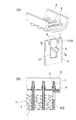
図1は、本発明の第1実施例の説明図であり、(A)はその要部組立て説明図であり、(B)はそのB−B横断面図である。なお、この例のコアサポート4はその溝型部分を省略している。また、コアサポート4の上端部と上側のヘッダープレート6との接続状態を部分的に示したものである。そして、コアサポート4の下側においても同様に組立てられる。
ここで、コアサポート4は予め、プレス成形により、その上下両端に挿通用端部7が形成される。挿通用端部7の横断面外周は、ヘッダープレート6の偏平孔5の内周に整合する。そして、その挿通用端部7には、幅方向に離間して一対のV字状欠切部9が設けられ、その幅方向両端位置に一対の端部変形容易部10が形成される。そして、挿通用端部7に隣接して、コアサポート4の端部に舌片がヘッダープレート6の下面に略平行に切り起こされて座部8を形成する。
FIGS. 1A and 1B are explanatory views of a first embodiment of the present invention, FIG. 1A is an explanatory view for assembling the main part, and FIG. The
Here, the
そして、同図1(B)の如く、コア3の偏平チューブ1およびコアサポート4を各偏平孔5に挿通し、ヘッダープレート6の端部を座部8に着座させる。これにより、ヘッダープレート6とコア3とが上下方向および左右方向に位置決めされる。
この例では、さらに図4に示す如く、コアサポート4の挿通用端部7の幅方向両端の一対の端部変形容易部10が幅方向に塑性変形され、偏平孔5の長軸の孔縁部に端部変形容易部10の塑性変形部7aが圧着される。それにより、一対の挿通用端部7が偏平孔5の長軸側の両縁部に仮固定される。
Then, as shown in FIG. 1B, the
In this example, as shown in FIG. 4, the pair of end
この状態で、図8に示す、ヘッダー本体15がヘッダープレート6に被嵌される。この時、端蓋13および仕切板14の凸部24がヘッダー本体15の係止孔20に嵌着する。そして、ヘッダー本体15の縁部に定間隔に突設されたカシメ爪19をヘッダープレート6の側壁にカシメ固定して、全体の仮組立てを完成する。
なお、互いに接触する各部品の少なくとも一方には、予め、ろう材が被覆され、又は塗布されている。そして、その仮組立て体を高温の炉内に挿入し、各部品間を一体的にろう付け固定するものである。
In this state, the header
Note that a brazing material is coated or applied in advance to at least one of the components that contact each other. Then, the temporary assembly is inserted into a high-temperature furnace and the parts are integrally brazed and fixed.
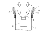
次に、図2は本発明の第2実施例の仮組立て手段を示し、この例が図1のそれと異なる点は、座部8の切り起こし方向にある。この例では、舌片がヘッダープレート6の下面に略垂直に切り起こされて座部8が形成され、その座部8の上端面が、ヘッダープレート6の平面に略平行に配置される。そして、その座部8の上端縁に図2(B)の如く、ヘッダープレート6が着座される。
この例においても、挿通用端部7の幅方向両端に位置する端部変形容易部10が、図4に示す如く、鎖線の状態から実線の状態に塑性変形され、偏平孔5の長軸の両端縁にその塑性変形部7aが圧着固定される。
Next, FIG. 2 shows a temporary assembling means of the second embodiment of the present invention, and this example is different from that of FIG. 1 in the direction in which the
Also in this example, the end
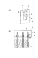
次に、図3は本発明の第3実施例を示し、この例が図2の例と異なる点は、コアサポート4の端部で、挿通用端部7に隣接して、その幅方向の両側に一対の舌片がヘッダープレート6の下面に略垂直に切り起こされて一対の座部8が形成された点である。なお、その上端面はヘッダープレート6の平面に略平行になっており、一対の座部8上にヘッダープレート6の平面が図3(B)の如く、着座するものである。
この例においても、挿通用端部7の幅方向両端に位置する端部変形容易部10が偏平孔5の長軸方向に塑性変形されて、その長軸側両縁に塑性変形部7aが圧着固定される。
Next, FIG. 3 shows a third embodiment of the present invention. This example is different from the example of FIG. 2 in that the end of the
Also in this example, the end
次に、図5は、本発明の第5実施例であり、この例が図1のそれと異なる点は、V字状欠切部9の形状である。図1の例では、V字状欠切部9がV字状に切り欠かれているが、図5の例では、U字状に切り欠かれたU字状欠切部9aが形成されている。
図6は、その挿通用端部7の塑性変形の他の例である。この例では、コアサポート4の幅方向の両端に位置する一対の端部変形容易部10が偏平孔の短径方向の一方側に塑性変形されるとともに、その中央に位置する中央変形容易部11が他方側に塑性変形され、それにより、コアサポート4の端部とヘッダープレート6とが圧着固定される。
次に図7は、図5に記載の挿通用端部7の塑性変形のまた別の例である。この例では、一対のU字状欠切部9a間に位置する中央変形容易部11が座部8側に塑性変形されて、それにより、コアサポート4とヘッダープレート6とが圧着固定される。
Next, FIG. 5 shows a fifth embodiment of the present invention, and this example is different from that of FIG. 1 in the shape of the V-shaped
FIG. 6 is another example of plastic deformation of the
Next, FIG. 7 is another example of plastic deformation of the
このようにコア3とヘッダープレート6とを位置決め仮固定した後に、ヘッダープレート6にヘッダ本体15を組合わせる。そして全体を高温の炉内に挿入し、一体にろう付けして、熱交換器を完成する。炉内では各部品が予め仮固定されているため、各部品が位置決めされた状態で、精度よくろう付けされる。
After the
上記の実施例では、熱交換器の一例として、凝縮器において説明したが、他の各種熱交換器、例えば、エンジン冷却用ラジエータ、インタークーラー、オイルクーラ、その他、に用いることができる。 In the above embodiment, the condenser has been described as an example of the heat exchanger. However, it can be used for other various heat exchangers such as an engine cooling radiator, an intercooler, an oil cooler, and the like.
1 偏平チューブ
2 フィン
3 コア
4 コアサポート
4a 側壁部
5 偏平孔
6 ヘッダープレート
7 挿通用端部
7a 塑性変形部
8 座部
DESCRIPTION OF
9 V字状欠切部
9a U字状欠切部
10 端部変形容易部
11 中央変形容易部
13 端蓋
14 仕切板
15 ヘッダー本体
16 入口パイプ
17 出口パイプ
9 V-shaped
18 冷媒
19 カシメ爪
20 係止孔
21 窓部
22 側部欠切部
23 ヘッダー
24 凸部
18
Claims (5)
前記コア(3)の各偏平チューブ(1)の先端部およびコアサポート(4)の先端部が挿通される偏平孔(5)が並列されたヘッダープレート(6)と、
を具備し、
前記コア(3)とヘッダープレート(6)との間が一体にろう付けされる熱交換器であって、そのろう付け前のヘッダープレートとコアとの仮組立て手段において、
前記コアサポート(4)の長手方向の端部に、前記偏平孔(5)に嵌合する挿通用端部(7)を有すると共に、そのコアサポート(4)の挿通用端部(7)に隣接して、その挿通用端部(7)よりコアサポート(4)の中央寄りに、前記ヘッダープレート(6)の平面を支持するための座部(8)がコアサポート(4)に一体に切り起こし形成され、
各偏平チューブ(1)の端部および、コアサポート(4)の挿通用端部(7)を、ヘッダープレート(6)の前記偏平孔(5)に挿通して、ヘッダープレート(6)を前記座部(8)に着座させたことを特徴とする熱交換器のヘッダープレートとコアとの仮組立て手段。 The flat tube (1) and the fin (2) are alternately arranged in parallel, and a core (3) in which a pair of core supports (4) are arranged at both ends in the parallel direction,
A header plate (6) in which a flat hole (5) through which the tip of each flat tube (1) of the core (3) and the tip of the core support (4) are inserted is arranged;
Comprising
A heat exchanger in which the core (3) and the header plate (6) are integrally brazed, and in the temporary assembly means of the header plate and the core before brazing,
At the end in the longitudinal direction of the core support (4), there is an insertion end (7) that fits into the flat hole (5), and the insertion end (7) of the core support (4) Adjacent to the insertion end (7), closer to the center of the core support (4), a seat (8) for supporting the plane of the header plate (6) is integrated with the core support (4). Cut and raised,
Insert the end of each flat tube (1) and the insertion end (7) of the core support (4) into the flat hole (5) of the header plate (6), and insert the header plate (6) Temporary assembly means of a header plate and a core of a heat exchanger characterized by being seated on a seat (8).
前記挿通用端部(7)の少なくとも一部を塑性変形させることにより、その塑性変形部(7a)を前記偏平孔(5)に圧着させたことを特徴とする熱交換器のヘッダープレートとコアとの仮組立て手段。 In the temporary assembly means of the header plate and the core of the heat exchanger according to claim 1,
A header plate and a core of a heat exchanger characterized in that at least a part of the insertion end (7) is plastically deformed so that the plastically deformed portion (7a) is crimped to the flat hole (5). And temporary assembly means.
前記偏平孔(5)がコアの幅方向に形成され、
前記挿通用端部(7)に、その先端に向かって拡開するV字状欠切部(9)(U字状欠切部(9a)を含む、以下同じ)を有し、そのV字の少なくとも片側に端部変形容易部(10)を形成しておき、その端部変形容易部(10)を塑性変形させることにより、その縁を偏平孔(5)の縁に圧着させたことを特徴とする熱交換器のヘッダープレートとコアとの仮組立て手段。 In the temporary assembly means of the header plate and the core of the heat exchanger according to claim 2,
The flat hole (5) is formed in the width direction of the core,
The insertion end (7) has a V-shaped notch (9) (including the U-shaped notch (9a), which is the same hereinafter) that expands toward the tip thereof. The end easily deformable portion (10) is formed on at least one side of the end portion, and the end easily deformable portion (10) is plastically deformed so that the edge thereof is crimped to the edge of the flat hole (5). A temporary assembly means of a header plate and a core of a heat exchanger as a feature.
前記挿通用端部(7)に、複数の前記V字状欠切部(9)をその幅方向に並列しておき、その幅方向両端に一対の端部変形容易部(10)を形成しておき、各端部変形容易部(10)を塑性変形させることにより、その縁を偏平孔(5)の両縁に圧着させたことを特徴とする熱交換器のヘッダープレートとコアとの仮組立て手段。 In the temporary assembly means of the header plate and the core of the heat exchanger according to claim 3,
A plurality of the V-shaped notches (9) are juxtaposed in the width direction at the insertion end (7), and a pair of end deformable portions (10) are formed at both ends in the width direction. Each of the end deformable portions (10) is plastically deformed so that the edges thereof are crimped to both edges of the flat holes (5). Assembly means.
前記挿通用端部(7)に、複数の前記V字状欠切部(9)を有し、それらの前記V字状欠切部(9)の間に少なくとも一つの中央変形容易部(11)を形成しておき、その中央変形容易部(11)をヘッダープレートの長手方向に折り曲げて、その曲げ部を偏平孔(5)の孔縁に圧着させたことを特徴とする熱交換器のヘッダープレートとコアとの仮組立て手段。 In the temporary assembly means of the header plate and the core of the heat exchanger according to claim 1,
The insertion end (7) has a plurality of the V-shaped notches (9), and at least one central deformable portion (11) between the V-shaped notches (9). ), And the central deformable portion (11) is bent in the longitudinal direction of the header plate, and the bent portion is crimped to the edge of the flat hole (5). Temporary assembly means of header plate and core.
Priority Applications (1)
| Application Number | Priority Date | Filing Date | Title |
|---|---|---|---|
| JP2015125010A JP2017009191A (en) | 2015-06-22 | 2015-06-22 | Temporary assembly means for header plate and core of heat exchanger |
Applications Claiming Priority (1)
| Application Number | Priority Date | Filing Date | Title |
|---|---|---|---|
| JP2015125010A JP2017009191A (en) | 2015-06-22 | 2015-06-22 | Temporary assembly means for header plate and core of heat exchanger |
Publications (1)
| Publication Number | Publication Date |
|---|---|
| JP2017009191A true JP2017009191A (en) | 2017-01-12 |
Family
ID=57763127
Family Applications (1)
| Application Number | Title | Priority Date | Filing Date |
|---|---|---|---|
| JP2015125010A Pending JP2017009191A (en) | 2015-06-22 | 2015-06-22 | Temporary assembly means for header plate and core of heat exchanger |
Country Status (1)
| Country | Link |
|---|---|
| JP (1) | JP2017009191A (en) |
Cited By (3)
| Publication number | Priority date | Publication date | Assignee | Title |
|---|---|---|---|---|
| WO2018159137A1 (en) * | 2017-03-03 | 2018-09-07 | 株式会社デンソー | Heat exchanger |
| WO2019198174A1 (en) * | 2018-04-11 | 2019-10-17 | 三菱電機株式会社 | Air conditioning device |
| JP2023130179A (en) * | 2022-03-07 | 2023-09-20 | 株式会社ティラド | Heat exchanger |
Citations (5)
| Publication number | Priority date | Publication date | Assignee | Title |
|---|---|---|---|---|
| JPS50127771U (en) * | 1974-04-04 | 1975-10-20 | ||
| JPS5629594Y2 (en) * | 1976-04-27 | 1981-07-14 | ||
| JPH0968397A (en) * | 1995-08-30 | 1997-03-11 | Calsonic Corp | Core part structure of heat exchanger |
| US20010037878A1 (en) * | 2000-04-10 | 2001-11-08 | Viktor Brost | Header-less vehicle radiator |
| JP3808593B2 (en) * | 1997-06-23 | 2006-08-16 | カルソニックカンセイ株式会社 | Core structure of heat exchanger |
-
2015
- 2015-06-22 JP JP2015125010A patent/JP2017009191A/en active Pending
Patent Citations (5)
| Publication number | Priority date | Publication date | Assignee | Title |
|---|---|---|---|---|
| JPS50127771U (en) * | 1974-04-04 | 1975-10-20 | ||
| JPS5629594Y2 (en) * | 1976-04-27 | 1981-07-14 | ||
| JPH0968397A (en) * | 1995-08-30 | 1997-03-11 | Calsonic Corp | Core part structure of heat exchanger |
| JP3808593B2 (en) * | 1997-06-23 | 2006-08-16 | カルソニックカンセイ株式会社 | Core structure of heat exchanger |
| US20010037878A1 (en) * | 2000-04-10 | 2001-11-08 | Viktor Brost | Header-less vehicle radiator |
Cited By (5)
| Publication number | Priority date | Publication date | Assignee | Title |
|---|---|---|---|---|
| WO2018159137A1 (en) * | 2017-03-03 | 2018-09-07 | 株式会社デンソー | Heat exchanger |
| WO2019198174A1 (en) * | 2018-04-11 | 2019-10-17 | 三菱電機株式会社 | Air conditioning device |
| JPWO2019198174A1 (en) * | 2018-04-11 | 2021-02-12 | 三菱電機株式会社 | Air conditioner |
| JP2023130179A (en) * | 2022-03-07 | 2023-09-20 | 株式会社ティラド | Heat exchanger |
| JP7830168B2 (en) | 2022-03-07 | 2026-03-16 | 株式会社ティラド | heat exchanger |
Similar Documents
| Publication | Publication Date | Title |
|---|---|---|
| KR100842337B1 (en) | Heat exchanger and method of making the same | |
| JP2007303813A (en) | Self-braking radiator side plate | |
| JP5663413B2 (en) | Serpentine heat exchanger | |
| US20180259269A1 (en) | Heat exchanger and manufacturing method for the same | |
| JP2017075741A (en) | Heat exchanger | |
| KR20150053135A (en) | Heat exchanger and Manufacturing method fo the same | |
| JPH09126685A (en) | Heat exchanger | |
| JP2017009191A (en) | Temporary assembly means for header plate and core of heat exchanger | |
| JP2005180904A (en) | End plate for heat exchanger, heat exchanger provided with the same, and manufacturing method thereof | |
| JP6674262B2 (en) | Heat exchanger and method of manufacturing the same | |
| JP6880206B2 (en) | How to make a heat exchanger | |
| JP2020076535A (en) | Heat exchanger and method for manufacturing heat exchanger | |
| JP5741470B2 (en) | Heat exchanger and method for manufacturing the same | |
| EP3578913B1 (en) | Heat exchanger and refrigeration cycle apparatus | |
| JP2014105951A (en) | Heat exchanger | |
| KR20070108078A (en) | How to connect the intermediate assembly and the heat exchanger | |
| WO2017018540A1 (en) | Heat exchanger header tank | |
| US7552756B2 (en) | Brazed aluminum radiator with PTO section and method of making the same | |
| JP2009198132A (en) | Tube for heat exchanger | |
| JPH11223477A (en) | Composite heat exchanger for automobile and manufacture thereof | |
| JP2019199978A (en) | Heat exchanger | |
| JP6632868B2 (en) | Aluminum heat exchanger | |
| JP5460212B2 (en) | Heat exchanger | |
| JP6037512B2 (en) | Heat exchanger with connector | |
| US20170307303A1 (en) | Heat exchanger |
Legal Events
| Date | Code | Title | Description |
|---|---|---|---|
| A621 | Written request for application examination |
Free format text: JAPANESE INTERMEDIATE CODE: A621 Effective date: 20180316 |
|
| A977 | Report on retrieval |
Free format text: JAPANESE INTERMEDIATE CODE: A971007 Effective date: 20181221 |
|
| A131 | Notification of reasons for refusal |
Free format text: JAPANESE INTERMEDIATE CODE: A131 Effective date: 20190108 |
|
| A521 | Request for written amendment filed |
Free format text: JAPANESE INTERMEDIATE CODE: A523 Effective date: 20190307 |
|
| A131 | Notification of reasons for refusal |
Free format text: JAPANESE INTERMEDIATE CODE: A131 Effective date: 20190625 |
|
| A521 | Request for written amendment filed |
Free format text: JAPANESE INTERMEDIATE CODE: A523 Effective date: 20190802 |
|
| A02 | Decision of refusal |
Free format text: JAPANESE INTERMEDIATE CODE: A02 Effective date: 20191029 |