JP2017009286A - Thin section sample preparation device and thin section sample preparation method - Google Patents
Thin section sample preparation device and thin section sample preparation method Download PDFInfo
- Publication number
- JP2017009286A JP2017009286A JP2013203548A JP2013203548A JP2017009286A JP 2017009286 A JP2017009286 A JP 2017009286A JP 2013203548 A JP2013203548 A JP 2013203548A JP 2013203548 A JP2013203548 A JP 2013203548A JP 2017009286 A JP2017009286 A JP 2017009286A
- Authority
- JP
- Japan
- Prior art keywords
- sample
- sample block
- thin
- temperature
- unit
- Prior art date
- Legal status (The legal status is an assumption and is not a legal conclusion. Google has not performed a legal analysis and makes no representation as to the accuracy of the status listed.)
- Pending
Links
- 238000002360 preparation method Methods 0.000 title claims abstract description 43
- 238000005464 sample preparation method Methods 0.000 title claims description 10
- 238000005520 cutting process Methods 0.000 claims abstract description 82
- 238000001514 detection method Methods 0.000 claims abstract description 40
- 238000000034 method Methods 0.000 claims abstract description 15
- 238000004441 surface measurement Methods 0.000 claims description 15
- 239000002344 surface layer Substances 0.000 claims description 10
- 230000032258 transport Effects 0.000 abstract description 35
- 239000000523 sample Substances 0.000 description 256
- 239000011521 glass Substances 0.000 description 26
- 238000003384 imaging method Methods 0.000 description 17
- 239000003795 chemical substances by application Substances 0.000 description 14
- XLYOFNOQVPJJNP-UHFFFAOYSA-N water Substances O XLYOFNOQVPJJNP-UHFFFAOYSA-N 0.000 description 9
- 238000003860 storage Methods 0.000 description 7
- 239000012472 biological sample Substances 0.000 description 6
- 239000007788 liquid Substances 0.000 description 6
- 238000007790 scraping Methods 0.000 description 6
- 230000008859 change Effects 0.000 description 5
- 238000001816 cooling Methods 0.000 description 5
- 239000012188 paraffin wax Substances 0.000 description 4
- 239000007921 spray Substances 0.000 description 4
- 241001465754 Metazoa Species 0.000 description 3
- 239000000853 adhesive Substances 0.000 description 3
- 230000001070 adhesive effect Effects 0.000 description 3
- 238000004458 analytical method Methods 0.000 description 3
- 230000008569 process Effects 0.000 description 3
- 238000012790 confirmation Methods 0.000 description 2
- 238000010586 diagram Methods 0.000 description 2
- 238000004519 manufacturing process Methods 0.000 description 2
- 238000012545 processing Methods 0.000 description 2
- 238000004378 air conditioning Methods 0.000 description 1
- 238000009529 body temperature measurement Methods 0.000 description 1
- 230000008602 contraction Effects 0.000 description 1
- 238000001035 drying Methods 0.000 description 1
- 238000007667 floating Methods 0.000 description 1
- 238000010438 heat treatment Methods 0.000 description 1
- 239000000463 material Substances 0.000 description 1
- 239000003595 mist Substances 0.000 description 1
- 238000012986 modification Methods 0.000 description 1
- 230000004048 modification Effects 0.000 description 1
- 230000004044 response Effects 0.000 description 1
- 238000005507 spraying Methods 0.000 description 1
- 238000012546 transfer Methods 0.000 description 1
- 238000011282 treatment Methods 0.000 description 1
- 238000011144 upstream manufacturing Methods 0.000 description 1
- 239000002699 waste material Substances 0.000 description 1
- 230000037303 wrinkles Effects 0.000 description 1
Images


Classifications
-
- G—PHYSICS
- G01—MEASURING; TESTING
- G01N—INVESTIGATING OR ANALYSING MATERIALS BY DETERMINING THEIR CHEMICAL OR PHYSICAL PROPERTIES
- G01N1/00—Sampling; Preparing specimens for investigation
- G01N1/02—Devices for withdrawing samples
- G01N1/04—Devices for withdrawing samples in the solid state, e.g. by cutting
- G01N1/06—Devices for withdrawing samples in the solid state, e.g. by cutting providing a thin slice, e.g. microtome
-
- G—PHYSICS
- G01—MEASURING; TESTING
- G01N—INVESTIGATING OR ANALYSING MATERIALS BY DETERMINING THEIR CHEMICAL OR PHYSICAL PROPERTIES
- G01N1/00—Sampling; Preparing specimens for investigation
- G01N1/28—Preparing specimens for investigation including physical details of (bio-)chemical methods covered elsewhere, e.g. G01N33/50, C12Q
- G01N1/30—Staining; Impregnating ; Fixation; Dehydration; Multistep processes for preparing samples of tissue, cell or nucleic acid material and the like for analysis
- G01N1/31—Apparatus therefor
- G01N1/312—Apparatus therefor for samples mounted on planar substrates
Landscapes
- Health & Medical Sciences (AREA)
- Life Sciences & Earth Sciences (AREA)
- General Health & Medical Sciences (AREA)
- Physics & Mathematics (AREA)
- Chemical & Material Sciences (AREA)
- Analytical Chemistry (AREA)
- Biochemistry (AREA)
- General Physics & Mathematics (AREA)
- Immunology (AREA)
- Pathology (AREA)
- Biomedical Technology (AREA)
- Molecular Biology (AREA)
- Engineering & Computer Science (AREA)
- Sampling And Sample Adjustment (AREA)
Abstract
Description
本発明は、理化学試料分析や生体試料等の顕微鏡観察などに利用される薄切片試料を作製する薄切片試料作製装置および薄切片試料作製方法に関する。 The present invention relates to a thin-section sample preparation apparatus and a thin-section sample preparation method for preparing a thin-section sample used for physicochemical sample analysis, microscopic observation of a biological sample and the like.
従来、理化学試料分析や生体試料等の顕微鏡観察等に利用される薄切片試料を作製するための装置としてミクロトームが広く知られている。ミクロトームは、動物の生体試料等の試料(被検体)をパラフィン等の包埋剤の中に埋め込んだ(包埋した)試料ブロックをカッターによって薄切りすることにより、薄切片試料を作製する装置である。例えば、特許文献1〜5には、試料ブロックの薄切り、スライドガラスへの貼付、伸展、乾燥という一連の動作を行う薄切片試料作製装置が記載されている。 2. Description of the Related Art Conventionally, a microtome is widely known as an apparatus for producing a thin slice sample used for physicochemical sample analysis or microscopic observation of a biological sample. A microtome is a device that produces a thin slice sample by slicing a sample block (embedded) in an embedding agent such as paraffin into a specimen block (embedded) such as a biological sample of an animal. . For example, Patent Documents 1 to 5 describe a thin-section sample preparation device that performs a series of operations such as slicing a sample block, sticking to a slide glass, stretching, and drying.
薄切片試料の厚さは非常に薄く(試料によって異なるが例えば3μm〜10μm)、かつ均一であることが求められる。さらに、動物の生体試料等は再度採取することが困難なものが多いため、所望の厚さを得ることができずに試料を無駄にすることは極力避けなければならない。一方で、この試料ブロックは、温度の微妙な変化によって膨張および収縮が発生しやすく、薄切り処理時に薄切片の厚さにムラが生じやすいという問題点を有する。 The thickness of the thin slice sample is required to be very thin (for example, 3 μm to 10 μm depending on the sample) and uniform. Furthermore, since many biological samples of animals are difficult to collect again, it is necessary to avoid as much as possible the waste of the sample without obtaining a desired thickness. On the other hand, this sample block has a problem that expansion and contraction are likely to occur due to a subtle change in temperature, and unevenness is likely to occur in the thickness of the thin slice during thin slice processing.
このため、環境を一定温度(例えば10℃〜25℃)に維持するように、薄切片試料作製装置は、一般的には筐体に囲われた装置内部を冷却する冷却機を備えている。上記温度の設定は、試料ブロックとして使用する試料および包埋剤の種類等に応じて適宜設定される。しかし、冷却機による温度調節では囲われた装置内部で温度がばらつき、装置内温度がほぼ所定温度になっている場合でも、試料ブロックの温度は所定の温度に達していない場合がある。また、試料ブロックの包埋剤の温度が、薄切片作製時までに十分に下がりきっていない場合もある。 For this reason, in order to maintain the environment at a constant temperature (for example, 10 ° C. to 25 ° C.), the thin-section sample preparation device is generally provided with a cooler that cools the inside of the device surrounded by a housing. The temperature is appropriately set according to the sample used as the sample block, the type of embedding agent, and the like. However, when the temperature is adjusted by the cooler, the temperature of the sample block may not reach the predetermined temperature even when the temperature varies within the enclosed apparatus and the temperature inside the apparatus is almost the predetermined temperature. In addition, the temperature of the embedding agent for the sample block may not be sufficiently lowered until the preparation of the thin section.
この対策として、薄切片試料作製装置の使用は、通常、冷却機を作動させてから30分程度時間をおいたうえで、切削工程等の薄切片作製動作が開始される。しかし、30分という設定時間は、試料ブロックの温度を考慮したものではなく、長すぎて単に時間のロスとなる場合もあれば、短すぎて試料ブロックの温度が下がりきらず、切削工程中の試料ブロックの温度変化により得られた薄切片に厚みムラが生じることもあり得る。 As a countermeasure, the use of the thin-section sample preparation device usually starts a thin-section preparation operation such as a cutting process after about 30 minutes have passed since the cooler is operated. However, the set time of 30 minutes does not take into account the temperature of the sample block, it may be too long and it may simply be a time loss, or it may be too short to reduce the temperature of the sample block, and the sample during the cutting process Thickness unevenness may occur in the thin slice obtained by the temperature change of the block.
上記の課題に対して、本発明では、試料ブロックの表面温度に基づいて、装置の薄切片作製動作を制御する。 In response to the above problem, in the present invention, the thin-section manufacturing operation of the apparatus is controlled based on the surface temperature of the sample block.
本発明の薄切片試料作製装置は、試料が包埋剤中に包埋された試料ブロックをカッターにより薄切りして薄切片試料を作製する薄切片試料作製装置であって、前記試料ブロックを搬送する搬送部と、前記カッターを備える切削部と、前記試料ブロックの表面温度を検出する温度検出部と、前記温度検出部により検出された前記試料ブロックの表面温度に基づいて少なくとも前記搬送部および/または前記切削部の動作を制御する制御部とを具備する。 The thin-section sample preparation apparatus of the present invention is a thin-section sample preparation apparatus that prepares a thin-section sample by slicing a sample block in which a sample is embedded in an embedding agent with a cutter, and transports the sample block A conveyance unit; a cutting unit including the cutter; a temperature detection unit that detects a surface temperature of the sample block; and at least the conveyance unit and / or based on the surface temperature of the sample block detected by the temperature detection unit. A control unit for controlling the operation of the cutting unit.
また、好ましくは、前記制御部は、前記試料ブロックの表面温度が前記所定の範囲外である場合は、該表面温度が前記所定の範囲内となるまで前記搬送部および/または前記切削部を停止させる。 Preferably, when the surface temperature of the sample block is outside the predetermined range, the control unit stops the conveying unit and / or the cutting unit until the surface temperature falls within the predetermined range. Let
また、好ましくは、上記いずれかの薄切片試料作製装置は、前記試料ブロック表面を加湿する加湿部をさらに具備し、前記加湿部は、前記切削部と前記温度検出部との間において加湿を行う。 Preferably, any of the thin-section sample preparation devices further includes a humidifying unit that humidifies the surface of the sample block, and the humidifying unit humidifies between the cutting unit and the temperature detecting unit. .
また、好ましくは、上記いずれかの薄切片試料作製装置は、前記試料ブロックの表面の前記試料の部分の面積が薄切片試料作製について十分であるか否か判定する面出し判定部をさらに具備し、前記温度検出部は、試料ブロックの表面の前記試料の部分の面積が薄切片試料作製について十分である判定をした場合に温度検出を行う。 Preferably, any one of the thin-section sample preparation apparatuses further includes a surface determination unit that determines whether an area of the sample portion on the surface of the sample block is sufficient for thin-section sample preparation. The temperature detection unit performs temperature detection when it is determined that the area of the sample portion on the surface of the sample block is sufficient for thin-section sample preparation.
本発明の薄切片試料作製方法は、試料が包埋剤中に包埋された試料ブロックの表層部分をカッターにより薄切りして薄切片試料を作製する薄切片試料作製方法であって、前記試料ブロックの表面温度を検出するステップと、前記表面温度が所定の範囲内であるか否かを判定するステップと、前記表面温度が前記所定の範囲内である場合は、前記カッターと前記試料ブロックとを相対的に移動させることにより前記薄切り動作を行い、前記表面温度が前記所定の範囲外である場合は、該表面温度が前記所定の範囲内となるまで前記試料ブロックを停止させるステップとを有する。 The thin-section sample preparation method of the present invention is a thin-section sample preparation method for preparing a thin-section sample by slicing a surface layer portion of a sample block in which the sample is embedded in an embedding agent with a cutter. Detecting the surface temperature, determining whether or not the surface temperature is within a predetermined range, and if the surface temperature is within the predetermined range, the cutter and the sample block Performing the slicing operation by relatively moving, and stopping the sample block until the surface temperature falls within the predetermined range when the surface temperature is outside the predetermined range.
また、好ましくは、上記薄切片試料作製方法は、前記表面温度が所定の範囲内であるか否かを判定するステップと、前記表面温度が前記所定の範囲内である場合は、前記カッターと前記試料ブロックとを相対的に移動させることにより前記薄切り動作を行うステップとの間に、前記試料ブロック表面を加湿するステップを有する。 Preferably, in the thin-section sample preparation method, the step of determining whether or not the surface temperature is within a predetermined range, and when the surface temperature is within the predetermined range, the cutter and the There is a step of humidifying the surface of the sample block between the step of performing the slicing operation by relatively moving the sample block.
本発明の薄切片試料作製装置または方法によれば、試料ブロックの表面温度に基づいて薄切片試料作製動作を制御するので、薄切片試料作製開始前の余計な待機時間を短縮することができ、かつ試料ブロック温度が変化することによる薄切片試料の厚さのムラを抑えることができる。 According to the thin-section sample preparation apparatus or method of the present invention, since the thin-section sample preparation operation is controlled based on the surface temperature of the sample block, it is possible to reduce an extra waiting time before the start of thin-section sample preparation, And the nonuniformity of the thickness of the thin slice sample due to the change of the sample block temperature can be suppressed.
本発明の第1の実施形態にかかる薄切片試料作製装置および方法について、まずその構成と動作の概略を図1に基づいて説明する。 An outline of the configuration and operation of the thin-section sample preparation apparatus and method according to the first embodiment of the present invention will be described with reference to FIG.
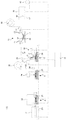
図1において、薄切片試料作製装置100は、試料ブロック10の表層部分をカッター31により自動的にかつ連続的に薄切りして薄切片試料16を作製する装置である。薄切片試料作製装置100は、試料ブロック搬送部20、試料ブロック収納部21、高さ検出部22、撮像部23、温度検出部24、切削部30、薄切片貼付部40、伸展部50、スライドガラス搬送部60、および装置全体を制御する制御部70を具備する。
In FIG. 1, a thin-section
試料ブロック10は、試料11をパラフィン等の包埋剤12の中に包埋したものである。被検体である試料11の例としては、例えば、人間や動物の組織などの生体試料が挙げられる。試料ブロック10は、表面のサイズが24mm×24mm、24mm×30mm、24mm×37mmであるものが一般的である。また、試料ブロック10の高さは5mm程度であることが一般的である。
The
図1において、試料ブロック収納部21には、複数の試料ブロック10を収納可能である。試料ブロック収納部21に収納された複数の試料ブロック10から選ばれた1つの試料ブロック10は、試料ブロック搬送部20により位置A(高さ検出部22)、位置B(撮像部23)、位置C(温度検出部24)を経て位置D(切削部30)へと搬送される。
In FIG. 1, a plurality of
なお、試料ブロック搬送部20は、試料ブロック10を取り出して位置Aに搬送したのち、当該試料ブロック10を位置A〜Dの間で往復搬送可能に構成されている。また、試料ブロック搬送部20は、試料ブロック10の傾きおよび高さ位置を調整可能に構成されている。最初に試料ブロック10の水平面に対する傾斜(傾き)が調整された後は、制御部70により制御される搬送部20が、切削量に応じて試料ブロック10の高さを適宜上げて調整する。
The sample block transport unit 20 is configured to be able to reciprocate the
位置Aの上方には、試料ブロック10の傾きと高さ位置を検出する高さ検出部22が配置されている。高さ検出部22としては、例えば、特許文献4に記載された、同一直線上にない少なくとも3つの接触式センサーで試料ブロック10の表面を検知するものを用いることができる。そのセンサー情報に基づいて、制御部70が搬送部20を制御することにより、試料ブロック10の傾きと高さ位置が調整される。
Above the position A, a height detection unit 22 that detects the inclination and height position of the
位置Bの上方には撮像部23が配置されている。撮像部23としては、例えば、特許文献2に記載されたように、光源とCCDカメラ等を有するものを用いることができる。撮像部23で得られた画像データを処理することによって、試料ブロック10の表面に露出した試料11の部分の面積が薄切片試料作製について十分であるか否かが制御部70で判定される。以下において、切削によって試料ブロック10表面に試料11を露出させることを「面出し」といい、露出した試料11の面積が薄切片試料作製に十分であるか否かの判定を「面出し判定」という。面出し判定の基準としては、例えば、試料ブロック10の切削面における試料11の露出面積が予め設定された面積比率よりも大きい場合に面出しが十分であるとすることができる。
An imaging unit 23 is disposed above the position B. As the imaging unit 23, for example, as described in
位置Cの上方には温度検出部24が配置されている。温度検出部24は、非接触式温度センサーを有し、試料ブロック10の表面温度を測定する。測定された温度が所定範囲内にあるか否かが制御部70で判定される。基準となる温度範囲は、パラフィン等の包埋剤の種類に応じて予め設定しておくことができる。
Above the position C, the temperature detector 24 is arranged. The temperature detection unit 24 has a non-contact temperature sensor and measures the surface temperature of the
位置Dの上方には切削部30が配置されている。切削部30は、試料ブロック10の表層部分を薄切可能なカッター31を有する。カッター31は、刃先が図1において紙面に垂直な方向に延在するように保持されている。本実施形態ではカッター31が固定されており、試料ブロック10が図1右方向に移動することによって、試料ブロック10の表面が薄切りされる。また、カッター31は、紙面に垂直な方向に移動可能に構成されていてもよい。その場合、試料ブロック10が図1右方向に移動すると同時にカッター31が紙面の奥から手前に移動することによって、試料ブロック10の表面が薄切りされる。切削部30では、試料ブロック10表面に試料11が十分に露出するまでの粗削り、試料11が十分に露出した後に薄切片の厚さが安定するまでの捨て削り、および薄切片試料16を切り出す本削りが行われる。なお、捨て削りについては省略される場合もある。
The cutting part 30 is disposed above the position D. The cutting unit 30 has a cutter 31 that can slice a surface layer portion of the
また、位置Dの上方には、試料ブロック10の表層部分がカッター31によって薄切りされることにより得られた薄切片試料16を保持するキャリアテープ33が供給される。キャリアテープ33は、供給リール32から繰り出され、ガイドローラ34,35に案内されて位置Dの上方に供給される。位置Dの上方で薄切片試料16を保持したキャリアテープ33は、ガイドローラ36,37に案内されて巻取リール38に巻き取られる。
Further, above the position D, a carrier tape 33 for holding a
キャリアテープ33に保持された薄切片試料16は、ガイドローラ36,37の間に配置された薄切片貼付部40によりスライドガラス17に貼り付けられる。薄切片貼付部40は、キャリアテープ33の走行経路の上流側に配置された一対のガイドローラ41,41と、キャリアテープ33の走行経路の下流側に配置された一対のガイドローラ42,42とを備えている。薄切片貼付部40は、一対のガイドローラ41,41の間と一対のガイドローラ42,42の間でキャリアテープ33を挟んで下方に撓ませ、当該キャリアテープ33に保持された薄切片試料16を、水などの接着液18が供給されたスライドガラス17に接触させる。これにより、薄切片試料16がスライドガラス17に貼り付けられる。以下、薄切片試料16が貼り付けられたスライドガラスを、薄切片付きスライドガラスという。
The
薄切片付きスライドガラス17は、スライドガラス搬送部60により伸展部50へ搬送される。スライドガラス搬送部60は、薄切片付きスライドガラス17を伸展部50へ搬送するとともに、スライドガラス収納部(図示せず)から薄切片試料を未貼付のスライドガラス17を取り出して薄切片貼付部40の下方へ搬送する。伸展部50は、加温板(図示せず)を備え、薄切片試料16の皺の伸展を行うとともに、スライドガラス17上の水分を蒸発させて薄切片試料16をスライドガラス17に密着固定する。
The slide glass 17 with a thin section is conveyed to the extension unit 50 by the slide
試料ブロック搬送部20などの各構成要素は、制御部70により動作を制御される。制御部70は、入力部(図示せず)に入力された情報に基づいて、各構成要素の動作を制御する。入力部は、例えば、薄切片付きスライドガラスの製作枚数や1枚のスライドガラス当たりの薄切片試料の貼り付け数などを入力可能に構成されている。 The operation of each component such as the sample block transport unit 20 is controlled by the control unit 70. The control unit 70 controls the operation of each component based on information input to an input unit (not shown). The input unit is configured to be able to input, for example, the number of manufactured slide glasses with thin sections, the number of thin section samples attached per slide glass, and the like.
また、装置100は図示しない筐体と冷却器を備え、筐体に囲われた装置内部が冷却器により冷却され、一定温度となるように空調されている。この温度設定は、試料ブロック10として使用する試料11および包埋剤12の種類等に応じて適宜設定される。設定温度は、典型的には10℃〜25℃の範囲にある。試料ブロック10の温度が高すぎると、包埋剤が軟らかいことで薄切片試料の品質が悪化するという問題を生じる。また、装置内部の温度と試料ブロック10の温度差が大きいと、試料ブロック10が温度変化によって収縮膨張し、連続して作製された薄切片間の厚さのばらつきが大きくなるという問題を生じる。さらに、試料ブロック10の温度が低すぎると、薄切片が割れるなどの問題を生じる。
The
次に、薄切片試料16の作製動作を、図1〜3に基づいて説明する。図2は試料ブロックの構造を示している。図3は本実施形態における薄切片試料作製のフローチャートを示している。この薄切片試料16の作製動作は、制御部70の制御の下に行われる。
Next, the manufacturing operation of the
図2において、試料ブロック10は、試料(被検体)11をパラフィン等の包埋剤12の中に包埋したものである。図2(a)は粗削り前の試料ブロックを正面方向から見た断面図であり、試料11は外部に露出しない(あるいは僅かに露出する)ように包埋剤12の中に埋め込まれている。収納部21に収納された試料ブロック10は、通常この状態である。試料ブロック10は、試料11の表面への露出面積が予め設定された面積以上になるまで表層部分を粗削りされる(図2(a)の点線14)。粗削りによって、試料11の露出面積が予め設定された面積以上になると(図2(b))、厚さが3〜10μm程度の薄切片試料16を作製するための捨て削りまたは本削りが行われる(図2(c)の点線15)。なお、試料ブロック10は、図1には図示されていない試料ブロック台13に載せて搬送される。また、図2の縮尺は正確ではなく、説明の容易のために高さ方向に引き伸ばされていることに留意されたい。
In FIG. 2, a
図1および図3を参照して、まず、試料ブロック搬送部20が試料ブロック収納部21から次に薄切り処理される試料ブロック10を取り出し、位置Aに搬送する。位置Aにおいて、試料ブロック10の傾きおよび高さ位置が調整される。
Referring to FIGS. 1 and 3, first, the sample block transport unit 20 takes out the
次いで、試料ブロック搬送部20が試料ブロック10を位置Bに搬送する。位置Bにおいて、撮像部23が試料ブロック10を撮像し、試料ブロック10の表面に露出した試料11の部分の面積が薄切片試料作製について十分であるか否かの面出し判定が行われる。なお、特許文献1の面出し判定の方法は、試料ブロックの試料の最大投影領域を検出し、試料ブロックの表面における試料の部分と包埋剤の部分とを識別し、試料ブロックの表面における試料の部分の面積の、試料ブロックの試料の最大投影領域の面積に対する割合が所定割合以上か否かにより、十分であるか否かを判定するものであり、それを用いることができる。なお、第1回目の撮像においては、試料ブロックの試料の最大投影領域を検出するのみとし、面出し判定を省略することも可能である。
Next, the sample block transport unit 20 transports the
次いで、試料ブロック搬送部20が試料ブロック10を位置Dに搬送する。位置Dにおいて、試料ブロック10の表層部分が切削部30によって粗削りされる。なお、第1回目の粗削りにおいても、位置Cに搬送し、表面温度検出・温度判定を行っても良い。
Next, the sample block transport unit 20 transports the
次いで、試料ブロック搬送部20が試料ブロック10を再度位置Bに搬送する。位置Bにおいて、粗削りによって露出した試料ブロック10の切削面を撮像部23が撮像し、再び又は第1回目の面出し判定が行われる。なお、2回目以降の撮像については、最大投影領域を検出することを必要としないため、1回目の撮像とは照射方法、検出方法等を変更することができる。
Next, the sample block transport unit 20 transports the
面出し判定において、面出しが十分でない場合は、再度試料ブロック搬送部20が試料ブロック10を位置Dに搬送され、位置Dにおいて、試料ブロック10の表層部分が切削部30によって粗削りされる。この場合は、表面温度検出・温度判定を行う必要がなく、より効率的に粗削りを行う。ただし、粗削りにおいても、位置Cに搬送し、表面温度検出・温度判定を行ってもよい。
In the surface determination, if the surface is not sufficient, the sample block transport unit 20 transports the
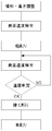
面出し判定において、面出しが十分であるとされた場合、すなわち粗削りの動作が完了したとされた場合は、試料ブロック搬送部20が試料ブロック10を位置Cに搬送し、位置Cにおいて、温度検出部24が試料ブロック10の表面温度を測定し、測定された温度が所定範囲内にあるか否かが判定される。試料ブロック表面温度が所定範囲内である場合は、位置Dに搬送し、次の捨て削り又は本削り工程へと進む。試料ブロック表面温度が所定範囲外である場合は、制御部70は試料ブロック搬送部20を停止し、表面温度が所定範囲内になるまで試料ブロック10をその場で待機させる。なお、試料ブロックを切削する場合、試料ブロックの湿度も重要であり切削前に加湿を行うことが多い。加湿を行うのは、表面温度検出・温度判定により測定された温度が所定範囲内にあるとされ、捨て削り又は本削りのために位置Dに搬送されるタイミングで行うのが好ましい。すなわち、位置Cと位置Dとの間に加湿部39があるのが好ましい。表面温度検出前に加湿を行うと、加湿してすぐには適切な温度測定ができないため、時間的なロスが生じるためである。
In the surface determination, if the surface is determined to be sufficient, that is, if the roughing operation is completed, the sample block transport unit 20 transports the
位置Dでは、本削りによって試料ブロック10表面から薄切片16が削り出される。このとき、通常は本削りと同じ厚さ・条件で複数回の捨て削りを行ってから、本削りが行われる。捨て削りを行うことによって、薄切片16の厚さが安定してくるからである。特に、粗削りと本削りとで異なるカッター31またはカッター31の刃先の異なる位置を使用する場合、あるいは粗削りの厚さと本削りの厚さが異なる場合は、作製される薄切片の厚さ精度を良くするために、本削りに使用されるカッター31および刃先の位置で、本削り厚さで数回の捨て削りを行うことが好ましい。
At the position D, the
本削り動作においては、試料ブロック10の表層部分がカッター31に薄切り(3μm〜10μm程度)されるように、試料ブロック搬送部20によって試料ブロック10の高さ位置が調整される。その後、試料ブロック10の表層部分がカッター31により薄切りされ、薄切片試料16が作製される。その後、試料ブロック搬送部20が、試料ブロック10を位置Dから位置C方向へ一旦退避させ、試料ブロック10の表層部分がカッター31に薄切りされるように試料ブロック10の高さ位置を調整し、次の本削りが行われる。この試料ブロック20の高さ位置の調整、薄切り、および退避の動作が、前記入力部(図示せず)に入力された情報に基づく任意の回数、自動的かつ連続的に繰り返され、任意の枚数の薄切片試料16が作製される。
In the main cutting operation, the height position of the
前記本削り動作により作製された薄切片試料16は、キャリアテープ33に貼り付けられる。なお、このとき、薄切片試料16がより確実にキャリアテープ33に貼り付くように、キャリアテープ33の表面に加湿、冷却および帯電などの処理をしておくことが好ましい。キャリアテープ33に貼り付けられた薄切片試料16は、薄切片貼付部40に搬送され、薄切片貼付部40によりスライドガラス17に貼り付けられる。その後、薄切片付きスライドガラスは、スライドガラス搬送部60により伸展部50へ搬送される。その後、伸展部50が、薄切片試料16の皺を伸展するとともに、薄切片試料16をスライドガラス17に密着固定させる。
The
本実施形態では、試料ブロック10は位置B〜Dの間を往復移動するので、搬送部20は試料ブロック10が位置B〜D間で往復移動可能に構成されている必要がある。また、試料ブロック10の高さ位置を切削の都度切削分だけ高くする位置調整は搬送部20で行われるので、通常は試料ブロックを位置Aに戻す必要はない。しかし、何らかの原因によって試料ブロック10の傾きを再調整する必要があるときに備えて、搬送部20は、試料ブロック10が位置A〜Dの間で往復移動可能に構成されていることが好ましい。
In this embodiment, since the
また、本実施形態では、温度検出部24の位置Cは位置BとDの間にあるが、これに限られるものではない。温度検出部24は、例えば、撮像部22(位置B)と同じ場所にあってもよく、切削部30(位置D)と同じ場所にあってもいい。さらに、搬送部20が試料ブロック10を往復移動可能な範囲内であれば、温度検出部24の物理的な位置は特に限定されない。なお、温度検出部24と切削部30とが同じ位置にある場合は、加湿部39も同じ位置に備えるのが好ましい。
In the present embodiment, the position C of the temperature detection unit 24 is between the positions B and D, but is not limited to this. For example, the temperature detection unit 24 may be in the same place as the imaging unit 22 (position B), or may be in the same place as the cutting unit 30 (position D). Furthermore, the physical position of the temperature detection unit 24 is not particularly limited as long as the transport unit 20 is within a range in which the
また、本実施形態では、位置Cにおいて、試料ブロック10の表面温度が所定範囲外である場合は、搬送部20がその場で停止した。しかし、表面温度が所定範囲外であった場合の動作もこれに限られるものではなく、搬送部20が試料ブロック10を位置C以外の場所に搬送して、時間をおいてから位置Cに戻して温度判定を行うようにしてもよい。
In the present embodiment, when the surface temperature of the
また、試料ブロック10の表面温度が所定範囲外であった場合に、本実施形態では、搬送部20を停止して、装置100内の空調によって試料ブロック10の温度が下がるまで温度検出位置または別の位置で待機する。このような試料ブロックを待機させる方法は、試料ブロック10内での温度変化が少なくなるため好ましい方法である。連続する薄切り枚数が多い場合に特に好ましい。ただし、試料ブロック10の冷却を速めるために強制冷却を行うことを妨げるものではなく、例えば、試料ブロック10の表面にペルチェ素子を接触させて、表面を冷却してもよい。
Further, in the present embodiment, when the surface temperature of the
また、本実施形態では、面出し判定および温度判定を行った後、複数回の捨て削りと複数回の本削りを連続して行っている。しかし、連続する切削動作の途中で試料ブロック表面の温度を確認してもよい。なお、捨て削りおよび本削りで切削される厚さは極めて薄いため、連続する切削動作の途中で試料ブロック表面の温度を確認しなくても、通常問題ない。 Further, in the present embodiment, after performing surface determination and temperature determination, a plurality of times of scraping and a plurality of times of main cutting are continuously performed. However, the temperature of the sample block surface may be confirmed during the continuous cutting operation. In addition, since the thickness cut by the discard cutting and the main cutting is extremely thin, there is usually no problem even if the temperature of the sample block surface is not confirmed during the continuous cutting operation.
また、粗削り前と、捨て削りまたは本削り前で、温度判定の基準となる温度範囲を異なる設定にしてもよい。 Further, the temperature range serving as a reference for temperature determination may be set differently before rough cutting and before scraping or main cutting.
次に、本発明の第2の実施形態を図1および図4に基づいて説明する。 Next, a second embodiment of the present invention will be described with reference to FIGS.
本実施形態では、上記第1の実施形態と同じ装置を用いる(図1)。図4は本実施形態における薄切片試料作製のフローチャートを示している。この薄切片試料16の作製動作は、制御部70の制御の下に行われる。本実施形態では、試料ブロック10の表面温度判定を行った後に、面出し判定を行う点で第1の実施形態と異なる。
In the present embodiment, the same apparatus as in the first embodiment is used (FIG. 1). FIG. 4 shows a flow chart of thin section sample preparation in this embodiment. The thin-
図1および図4を参照して、試料ブロック10は、位置Aで傾きおよび高さ位置を調整され、位置Cで表面温度検出と温度判定が行われる。試料ブロック10は、表面温度が所定範囲外であればその場で待機し、所定範囲内であれば位置Bに移動して撮像、面出し判定が行われる。試料ブロック10は、面出しが不十分であれば位置Dに移動して切削部30にて粗削りが行われ、その後に再び位置Cに戻って温度判定が行われる。このように、表面温度検出・温度判定、撮像・面出し判定、粗削りの動作は、試料ブロック10の面出しが十分に行われるまで繰り返される。位置Bにおいて面出しが十分であると判断されると、試料ブロック10は位置Dに移動して切削部30にて捨て削り、本削りが行われる。撮像部23、温度検出部24、切削部30等の装置各部の個々の動作は第1の実施形態と同じであるので、詳細な説明は省略する。
Referring to FIGS. 1 and 4, the
本実施形態においても、第1の実施形態と同様に、装置の構造や動作ステップの様々な変更が可能である。例えば、温度検出部24の物理的な位置、表面温度が所定の範囲外であったときの試料ブロック10の待機場所、強制冷却の有無、連続する切削動作の途中での試料ブロック表面温度の確認などについて、第1の実施形態と同様の変更が可能である。
Also in the present embodiment, various changes in the structure and operation steps of the apparatus are possible as in the first embodiment. For example, the physical position of the temperature detection unit 24, the standby position of the
なお、本実施形態では、加湿のための水の噴霧の影響に注意する必要がある。薄切片試料作製装置100においては、いくつかの動作にともなって試料ブロック10表面の加湿のために水が噴霧されることがある。通常は切削時の試料表面の湿度を適正化するために加湿するのであるが、それとは別に撮像部23において、試料11と包埋剤12のコントラストを上げるために、水を噴霧して試料ブロック表面を加湿することがある。このとき、試料ブロック10上方に霧が舞っている状態や、試料ブロック表面に噴霧された水滴が残った状態で温度を検出しても、正確な判定を行うことが難しい。撮像部23では、同様に水の噴霧による画像への影響を避けるために、水を噴霧してからしばらく時間をおいてから撮像が行われる。そのため、面出し判定直後に表面温度検出を行っても、温度判定が水の噴霧の影響を受けることはない。しかし、本実施形態では、切削動作の次に温度検出動作が行われるので、切削から温度検出までの間に、噴霧の影響がなくなるまで、一定の時間をおくことが好ましい。
In this embodiment, it is necessary to pay attention to the influence of water spray for humidification. In the thin-section
本発明の第3の実施形態を図6および図5に基づいて説明する。 A third embodiment of the present invention will be described with reference to FIGS.
本実施形態の薄切片試料作製装置は、図6に示すように、撮像部(図1の23)を有しない点で第1および第2の実施形態のそれと異なる。その他の構成は第1および第2の実施形態と同じである。図5は本実施形態における薄切片試料作製のフローチャートを示している。この薄切片試料16の作製動作は、制御部70の制御の下に行われる。
As shown in FIG. 6, the thin-section sample preparation apparatus of this embodiment differs from that of the first and second embodiments in that it does not have an imaging unit (23 in FIG. 1). Other configurations are the same as those in the first and second embodiments. FIG. 5 shows a flowchart of thin section sample preparation in the present embodiment. The thin-
図6および図5を参照して、試料ブロック10は、位置Aで傾きおよび高さ位置を調整され、位置Dに移動して切削部30にて粗削りが行われる。本実施形態では、面出し判定を行う撮像部がないため、予め定められた厚さを粗削りしたり、作業員が目視で確認しながら、面出しが十分に行われるまで粗削りを繰り返したりすることになる。十分に面出しが行われた後に、位置Cで試料ブロック10の表面温度検出と温度判定が行われる。試料ブロック10は、表面温度が所定範囲外であればその場で待機し、所定範囲内であれば位置Dに移動して切削部30にて捨て削り、本削りが行われる。なお、粗削り前に1度又は複数回位置Cに搬送し、表面温度検出・温度判定を行ってもよい。温度検出部24、切削部30等の装置各部の個々の動作は第1の実施形態と同じであるので、詳細な説明は省略する。
With reference to FIGS. 6 and 5, the
本実施形態においても、第1および第2の実施形態と同様に、装置の構造や動作ステップの様々な変更が可能である。例えば、温度検出部24の物理的な位置、表面温度が所定の範囲外であったときの試料ブロック10の待機場所、強制冷却の有無、連続する切削動作の途中での試料ブロック表面温度の確認などについて、第1または第2の実施形態と同様の変更が可能である。
Also in the present embodiment, various changes in the structure and operation steps of the apparatus can be made as in the first and second embodiments. For example, the physical position of the temperature detection unit 24, the standby position of the
本発明は、上記の実施形態に限定されるものではなく、その技術的思想の範囲内で種々の変形が可能である。例えば、装置筐体内の温度を測定するために、温度検出部24とは別に温度計を配置し、当該温度計と制御部とをリンクさせ、筐体内自体がある設定温度範囲内でなければ、装置全体をスタートできないようにすることも可能である。また、薄切片試料をスライドガラスの上面に載置する方法としては前記水などの接着液を用いた貼着による方法が最も好ましいが、その他の例としては、液槽内の液体に浮かべた薄切片試料を、スライドガラスで掬い上げるようにしてもよい。また、移載液の表面張力によって、薄切片試料がキャリアテープからスライドガラス上に移載されるようにしてもよい。 The present invention is not limited to the above-described embodiment, and various modifications can be made within the scope of the technical idea. For example, in order to measure the temperature in the device housing, a thermometer is arranged separately from the temperature detection unit 24, the thermometer and the control unit are linked, and the housing itself is not within a set temperature range, It is also possible to prevent the entire device from starting. In addition, as a method of placing the thin slice sample on the upper surface of the slide glass, the method by sticking using an adhesive liquid such as water is most preferable, but as another example, the thin slice sample floated on the liquid in the liquid tank. The section sample may be scooped up with a slide glass. Further, the thin slice sample may be transferred from the carrier tape onto the slide glass by the surface tension of the transfer liquid.
本発明の薄切片試料作製装置および方法では、試料ブロックの表面温度を検出して、表面温度が所定の温度範囲内にあることを確認した後に、薄切片試料を作製する。これにより、試料ブロック温度が高すぎることによる薄切片試料の厚さのムラを抑えることができるので、理化学試料分析や生体試料等の顕微鏡観察などに利用される薄切片試料作製装置および方法として有用である。 In the thin-section sample preparation apparatus and method of the present invention, the surface temperature of the sample block is detected, and after confirming that the surface temperature is within a predetermined temperature range, the thin-section sample is prepared. This makes it possible to suppress uneven thickness of the thin slice sample due to the sample block temperature being too high, and is useful as a thin slice sample preparation device and method used for physicochemical sample analysis and microscopic observation of biological samples. It is.
10 試料ブロック
11 試料(被検体)
12 包埋剤
13 試料ブロック台
14 荒削り高さ
15 捨て削りまたは本削り高さ
16 薄切片試料
17 スライドガラス
18 接着液
20 試料ブロック搬送部
21 試料ブロック収納部
22 高さ検出部
23 撮像部
24 温度検出部
30 切削部
31 カッター
32 供給リール
33 キャリアテープ
34〜37,41,42 ガイドローラ
38 巻取リール
39 加湿部
40 薄切片貼付部
50 伸展部
60 スライドガラス搬送部
70 制御部
100 薄切片試料作製装置
10
12 Embedding
Claims (6)
前記試料ブロックを搬送する搬送部と、
前記カッターを備える切削部と、
前記試料ブロックの表面温度を検出する温度検出部と、
前記温度検出部により検出された前記試料ブロックの表面温度に基づいて、少なくとも前記搬送部および/または前記切削部の動作を制御する制御部と、
を具備する薄切片試料作製装置。 A thin-section sample preparation device for preparing a thin-section sample by slicing a sample block in which a sample is embedded in an embedding agent with a cutter,
A transport unit for transporting the sample block;
A cutting section comprising the cutter;
A temperature detector for detecting the surface temperature of the sample block;
Based on the surface temperature of the sample block detected by the temperature detector, at least a controller that controls the operation of the transport unit and / or the cutting unit;
A thin-section sample preparation apparatus comprising:
請求項1に記載の薄切片試料作製装置。 When the surface temperature of the sample block is outside the predetermined range, the control unit stops the transport unit and / or the cutting unit until the surface temperature falls within the predetermined range.
The thin-section sample preparation apparatus according to claim 1.
前記加湿部は、前記切削部と前記温度検出部との間において加湿を行う、
請求項1または2に記載の薄切片試料作製装置。 Further comprising a humidifying part for humidifying the sample block surface;
The humidification unit performs humidification between the cutting unit and the temperature detection unit.
The thin-section sample preparation apparatus according to claim 1 or 2.
前記温度検出部は、試料ブロックの表面の前記試料の部分の面積が薄切片試料作製について十分である判定をした場合に温度検出を行う、
請求項1〜3のいずれか一項に記載の薄切片試料作製装置。 A surface determination unit that determines whether the area of the sample portion on the surface of the sample block is sufficient for thin-section sample preparation;
The temperature detection unit performs temperature detection when it is determined that the area of the sample portion on the surface of the sample block is sufficient for thin-section sample preparation,
The thin-section sample preparation apparatus as described in any one of Claims 1-3.
前記試料ブロックの表面温度を検出するステップと、
前記表面温度が所定の範囲内であるか否かを判定するステップと、
前記表面温度が前記所定の範囲内である場合は、前記カッターと前記試料ブロックとを相対的に移動させることにより前記薄切り動作を行い、前記表面温度が前記所定の範囲外である場合は、該表面温度が前記所定の範囲内となるまで前記試料ブロックを停止させるステップと、
を有する薄切片試料作製方法。 A thin-section sample preparation method for preparing a thin-section sample by slicing a surface layer portion of a sample block in which a sample is embedded in an embedding agent with a cutter,
Detecting the surface temperature of the sample block;
Determining whether the surface temperature is within a predetermined range;
When the surface temperature is within the predetermined range, the slicing operation is performed by relatively moving the cutter and the sample block, and when the surface temperature is outside the predetermined range, Stopping the sample block until the surface temperature is within the predetermined range;
A method for preparing a sliced piece sample.
前記表面温度が前記所定の範囲内である場合は、前記カッターと前記試料ブロックとを相対的に移動させることにより前記薄切り動作を行うステップとの間に、前記試料ブロック表面を加湿するステップを有する、
薄切片試料作製方法。 Determining whether the surface temperature is within a predetermined range;
A step of humidifying the surface of the sample block between the step of performing the slicing operation by relatively moving the cutter and the sample block when the surface temperature is within the predetermined range; ,
Thin section sample preparation method.
Priority Applications (2)
| Application Number | Priority Date | Filing Date | Title |
|---|---|---|---|
| JP2013203548A JP2017009286A (en) | 2013-09-30 | 2013-09-30 | Thin section sample preparation device and thin section sample preparation method |
| PCT/JP2014/075190 WO2015046202A1 (en) | 2013-09-30 | 2014-09-24 | Sliced-sample production device and sliced-sample production method |
Applications Claiming Priority (1)
| Application Number | Priority Date | Filing Date | Title |
|---|---|---|---|
| JP2013203548A JP2017009286A (en) | 2013-09-30 | 2013-09-30 | Thin section sample preparation device and thin section sample preparation method |
Publications (1)
| Publication Number | Publication Date |
|---|---|
| JP2017009286A true JP2017009286A (en) | 2017-01-12 |
Family
ID=52743338
Family Applications (1)
| Application Number | Title | Priority Date | Filing Date |
|---|---|---|---|
| JP2013203548A Pending JP2017009286A (en) | 2013-09-30 | 2013-09-30 | Thin section sample preparation device and thin section sample preparation method |
Country Status (2)
| Country | Link |
|---|---|
| JP (1) | JP2017009286A (en) |
| WO (1) | WO2015046202A1 (en) |
Cited By (2)
| Publication number | Priority date | Publication date | Assignee | Title |
|---|---|---|---|---|
| JP2017064542A (en) * | 2017-01-23 | 2017-04-06 | 株式会社大都技研 | Amusement stand |
| JP2023541825A (en) * | 2020-09-08 | 2023-10-04 | クララパス, インコーポレイテッド | Automated tissue section transfer system with high throughput |
Families Citing this family (1)
| Publication number | Priority date | Publication date | Assignee | Title |
|---|---|---|---|---|
| CN111929136A (en) * | 2020-08-28 | 2020-11-13 | 广州金域医学检验中心有限公司 | Staining method, device and system for frozen pathological section |
Family Cites Families (4)
| Publication number | Priority date | Publication date | Assignee | Title |
|---|---|---|---|---|
| JP4636552B2 (en) * | 2006-01-25 | 2011-02-23 | セイコーインスツル株式会社 | Automatic slicer |
| JP4668845B2 (en) * | 2006-06-05 | 2011-04-13 | 株式会社前川製作所 | Micro slicer |
| JP2008216109A (en) * | 2007-03-06 | 2008-09-18 | Toppan Printing Co Ltd | Cutting method |
| JP2012229993A (en) * | 2011-04-26 | 2012-11-22 | Kurabo Ind Ltd | Thin-sliced sample fabrication device and thin-sliced sample fabrication method |
-
2013
- 2013-09-30 JP JP2013203548A patent/JP2017009286A/en active Pending
-
2014
- 2014-09-24 WO PCT/JP2014/075190 patent/WO2015046202A1/en not_active Ceased
Cited By (3)
| Publication number | Priority date | Publication date | Assignee | Title |
|---|---|---|---|---|
| JP2017064542A (en) * | 2017-01-23 | 2017-04-06 | 株式会社大都技研 | Amusement stand |
| JP2023541825A (en) * | 2020-09-08 | 2023-10-04 | クララパス, インコーポレイテッド | Automated tissue section transfer system with high throughput |
| JP7817989B2 (en) | 2020-09-08 | 2026-02-19 | クララパス, インコーポレイテッド | Automated tissue section transport system with high throughput |
Also Published As
| Publication number | Publication date |
|---|---|
| WO2015046202A1 (en) | 2015-04-02 |
Similar Documents
| Publication | Publication Date | Title |
|---|---|---|
| JP5827490B2 (en) | Thin section sample preparation equipment | |
| JP4607703B2 (en) | Thin section preparation method | |
| US8025842B2 (en) | Apparatus and method for preparing sliced specimen | |
| US20230314284A1 (en) | Method, system, and device for automating transfer of tape to microtome sections | |
| JP4840763B2 (en) | Automatic thin section preparation apparatus and automatic thin section preparation apparatus | |
| JP5102149B2 (en) | Thin section preparation equipment | |
| US7374907B1 (en) | System and method for automatically processing tissue samples | |
| JP2003294591A (en) | Method and device for forming tissue section | |
| JP2004028910A (en) | Apparatus and method for preparing sliced sample | |
| WO2015046202A1 (en) | Sliced-sample production device and sliced-sample production method | |
| JP2012229993A (en) | Thin-sliced sample fabrication device and thin-sliced sample fabrication method | |
| CN102917845B (en) | Laminate film cutting device and laminate film cutting method | |
| JP6483022B2 (en) | Thin section sample evaluation apparatus, thin section sample preparation apparatus including the thin section sample evaluation apparatus, and thin section sample evaluation method | |
| JP4854442B2 (en) | Thin section sample preparation method and apparatus | |
| JP4795181B2 (en) | Sample block surface placement method | |
| WO2012147787A1 (en) | Thin section sample preparation device | |
| JP2016176842A (en) | Thin section sample preparation equipment | |
| JP5102148B2 (en) | Thin section manufacturing apparatus and thin section transport method | |
| JP2016085173A (en) | Thin section sample preparation device and thin section sample preparation method | |
| JP5193085B2 (en) | Thin section manufacturing apparatus and thin section manufacturing method | |
| JP2010185818A (en) | System for making thin slice | |
| JP2012229996A (en) | Thin-sliced sample fabrication device | |
| US20250264383A1 (en) | Microtome with automated adjustment and method therefor | |
| JP5102150B2 (en) | Thin section manufacturing apparatus and thin section transport method | |
| JP7404815B2 (en) | Glass roll manufacturing method |