JP2017009645A - Cooling device and image projection device including the same - Google Patents
Cooling device and image projection device including the same Download PDFInfo
- Publication number
- JP2017009645A JP2017009645A JP2015121846A JP2015121846A JP2017009645A JP 2017009645 A JP2017009645 A JP 2017009645A JP 2015121846 A JP2015121846 A JP 2015121846A JP 2015121846 A JP2015121846 A JP 2015121846A JP 2017009645 A JP2017009645 A JP 2017009645A
- Authority
- JP
- Japan
- Prior art keywords
- cooling
- position information
- fan
- altitude
- power supply
- Prior art date
- Legal status (The legal status is an assumption and is not a legal conclusion. Google has not performed a legal analysis and makes no representation as to the accuracy of the status listed.)
- Pending
Links
Images

Landscapes
- Transforming Electric Information Into Light Information (AREA)
- Cooling Or The Like Of Electrical Apparatus (AREA)
- Projection Apparatus (AREA)
Abstract
Description
本発明は、冷却装置及びこれを備えた画像投射装置に関するものである。 The present invention relates to a cooling device and an image projection device including the cooling device.
従来から、発熱源としての光源を有する画像投射装置などの電子装置において、当該発熱源を冷却する冷却装置が知られている。 Conventionally, in an electronic apparatus such as an image projection apparatus having a light source as a heat source, a cooling device for cooling the heat source is known.
特許文献1には、衛星からの電波を受信することで画像投射装置の設置場所の位置情報を得て、その位置情報に基づいて算出した高度に応じ、発熱源としての光源を空冷する冷却ファンの回転数を制御する冷却装置を備える画像投射装置が記載されている。この画像投射装置の冷却装置では、画像投射装置の設置場所が気圧の低い高所である場合には、冷却ファンの回転数を下げる。一方、画像投射装置の設置場所の高度が低い場合には、冷却ファンの回転数を上げる。これらにより、設置場所の高度の相違に応じた過不足のない冷却効果が得られるとしている。
また、特許文献2には、電源に入力される定格電源電圧を検出し、その定格電源電圧に基づいて発熱源の電源を冷却する冷却ファンの回転数を制御する冷却装置を備えた画像投射装置が記載されている。この画像投射装置の冷却装置では、定格電源電圧は国や地域によって異なり発熱源の発熱量が相違するので、検出した定格電源電圧が低くなった場合には冷却ファンの回転数を上げる制御を行い、不足する冷却効果を高める。一方、定格電源電圧が高くなった場合には冷却ファンの回転数を下げる制御を行い、過度の冷却効果を下げている。これらにより、定格電源電圧の相違に応じた過不足のない冷却効果を得ることができるとしている。 Patent Document 2 discloses an image projection apparatus including a cooling device that detects a rated power supply voltage input to a power supply and controls the number of revolutions of a cooling fan that cools the power supply of a heat source based on the rated power supply voltage. Is described. In this image projector cooling device, the rated power supply voltage differs depending on the country or region, and the heat generation amount of the heat source is different.Therefore, when the detected rated power supply voltage becomes low, control is performed to increase the rotation speed of the cooling fan. Increase the cooling effect, which is insufficient. On the other hand, when the rated power supply voltage becomes high, control is performed to reduce the rotational speed of the cooling fan, thereby reducing the excessive cooling effect. By these, it is supposed that the cooling effect without excess and deficiency according to the difference of a rated power supply voltage can be acquired.
特許文献1に開示の画像投射装置の冷却装置によれば、国や地域毎の定格電源電圧の相違により発熱源の発熱量が相違すると、衛星からの電波から得られた位置情報に基づく高度に応じて冷却ファンの回転数を制御しただけでは、最適な冷却ファンの回転数を制御することができない。一方、特許文献2に開示の冷却装置のように、設置場所の定格電源電圧の相違に応じて冷却ファンの回転数を最適に制御しようとすると、電源に入力される定格電源電圧を検出する回路が必要になる。その検出回路を特許文献1の冷却装置に備えると定格電源電圧の相違に対しても冷却ファンの回転数を最適に制御できる。しかし、当該検出回路を設けるので、コストアップになる。
According to the cooling device of the image projection apparatus disclosed in
上述した課題を解決するために、請求項1の発明は、発熱源を冷却する冷却手段と、該冷却手段を制御する制御手段とを備えた冷却装置において、前記発熱源の設置場所の位置情報を取得する位置情報取得手段と、位置情報に対応する定格電源電圧と標高情報とを記憶する記憶手段とを備え、前記制御手段は、前記位置情報取得手段によって取得した位置情報をもとに前記記憶手段を参照して得られた前記定格電源電圧と前記標高情報とに応じて、前記冷却手段を制御することを特徴するものである。
In order to solve the above-mentioned problem, the invention of
本発明によれば、発熱源に対する冷却効果を向上させることができるという特有の効果が得られる。 According to the present invention, it is possible to obtain a specific effect that the cooling effect on the heat source can be improved.
以下、本発明が適用される画像投射装置としてのプロジェクタ1の実施形態について説明する。
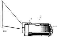
図1は、本実施形態1に係るプロジェクタ1を示す斜視図である。図2は右側面図である。図1及び図2に示すように、プロジェクタ1の上面には、ユーザがプロジェクタ1を操作するための操作ボタン等の操作部11が設けられている。また、スクリーン200に映し出されている投射画面を拡大したり、縮小したりするズームレバー12が設けられている。
Hereinafter, an embodiment of a
FIG. 1 is a perspective view showing a
プロジェクタ1の正面には、装置電源のオン/オフを行う電源スイッチ13、パソコンやビデオカメラ等の外部機器と接続するための外部入力端子14、投射画像の光を出射する投射レンズ15、装置環境の照度を検出するセンサ16などが設けられている。プロジェクタ1の正面には、排気口18が設けられている。プロジェクタ1における外装カバーの右側面には、冷却用の空気を取り入れる吸気口17が設けられている。
On the front side of the
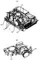
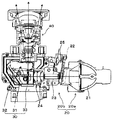
図3(a)は外装カバーを外したプロジェクタ1の内部構成と配置を示す斜視図、図3(b)は図3(a)の太線枠で囲まれた部分の斜視図である。図4は、投影機構部を構成する光源部、画像生成部、及び投射光学部の横断面図である。
図3及び図4に示すように、プロジェクタ1は、ハロゲンランプ、メタルハライドランプ、高圧水銀ランプなど放電ランプ21を備える光源部20を備えている。また、放電ランプ21からの光を用いて画像を生成する画像生成部30、投射画像を出射する投射光学部40を備えている。
FIG. 3A is a perspective view showing the internal configuration and arrangement of the
As shown in FIGS. 3 and 4, the
光源部20は、放電ランプ21を有する光源ユニット20aと、カラーホイール22、ライトトンネル23、2枚のリレーレンズ24を有する画像照明光学系20bとで構成されている。
The
そして、放電ランプ21からの光は、図4の矢印で示すように、回転するカラーホイール22を通ることにより時分割でR、G、Bの光に分離される。このカラーホイール22は、円盤形状のものであり、ホイールモータ25のモータ軸に固定され、回転方向にR(レッド)、G(グリーン)、B(ブルー)などのフィルタが設けられている。カラーホイール22により分離された光は、ライトトンネル23へ入射する。ライトトンネル23は、四角筒形状であり、その内周面が鏡面となっている。ライトトンネル23に入射した光は、ライトトンネル23の内周の鏡面で複数回反射しながら、均一な面光源にされて2枚のリレーレンズ24へ向けて出射する。図4の矢印で示すように、2枚のリレーレンズ24を透過し、次段の画像生成部30の平面ミラー31、凹面ミラー32により反射され、画像表示素子たるDMD(Digital Mirror Device)33の画像生成面上に集光して結像される。
The light from the
ここで、DMD33の画像生成面には、可動式の複数のマイクロミラーが格子状に配列されている。各マイクロミラーは、鏡面をねじれ軸周りに所定角度傾斜させることができ、「ON」と「OFF」の2つの状態を持たせることができる。マイクロミラーが「ON」のときは、光源部20の放電ランプ21からの光を投射光学部40の投射レンズに向けて反射する。「OFF」のときは、照明ブラケットなどの側面に保持されたOFF光板に向けて放電ランプ21からの光を反射する。従って、各ミラーを個別に駆動することにより、画像データの画素ごとに光の投射を制御することができ、画像を生成することができる。なお、OFF光板に向けて反射された光は、熱となって吸収され外側の空気の流れで冷却される。
Here, a plurality of movable micromirrors are arranged in a grid pattern on the image generation surface of the
図1に示すプロジェクタ1は、パソコンやビデオカメラ等から入力される映像データを基に映像を生成し、その映像を図2の投射面としてのスクリーン200等に投射表示する。プロジェクタ1として広く知られた液晶プロジェクタは、近来、液晶パネルの高解像化、光源ランプの高効率化に伴う明るさの改善、低価格化などが進んでいる。また、画像表示素子であるDMDを利用した小型で、軽量なプロジェクタ1が普及し、オフィスや学校のみならず家庭においても広く利用されるようになってきている。放電ランプ21からの光が、光源部20内で、照射された白色光をカラーホイール22によってRGBに分光されて、画像生成部30のDMD33へ導かれ、変調信号に応じて画像形成するDMD33とその画像を投射光学部40で拡大投射する。
A
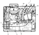
図5は、プロジェクタ1における吸気から排気の流れについて説明する図である。
図5に示すように、プロジェクタ1の内部には、冷却手段として、吸気口17と対向するように吸気ファン61と、排気口18から装置内の空気を排気する2つの排気ファン62a、62bと、遠心力ファン63とを備えている。
FIG. 5 is a diagram for explaining the flow of intake to exhaust in the
As shown in FIG. 5, the
図5に示すように、吸気ファン61により吸気口17から取り入れられた冷却用の空気は、吸気ファン61から光源ファン62までの空気の流路(図5中の矢印Aで示す)上に配置された電源ユニット51を冷却する。配置された電源ユニット51を冷却する。その後、光源ユニット20aを収納する光源ハウジングに設けられた流出口を通って、排気ファン63bにより排気口18から排気される。
As shown in FIG. 5, the cooling air taken from the
また、吸気ファン61により吸気口17から取り入れられた冷却用の空気は、吸気ファン61からの空気の流路(図5中の矢印Bで示す)を通って遠心力ファン63に吸気される。その後、2つの空気に分かれて光源ユニット20aを冷却する。一方の空気の流路(図5中の矢印Cで示す)を通って遠心力ファン63から排気ファン62aにより排気口18から排気され、他方の空気の流路(図5中の矢印Dで示す)は排気ファン62bにより排気口18から排気される。
The cooling air taken in from the
なお、本実施形態では、例えば日本のように定格電源電圧が100[V]と低電圧である場合では、図5の吸気ファン61の回転数を上げて冷却効果を上げている。一方、例えば欧州のように定格電源電圧が220〜240[V]と高電圧である場合では、吸気ファン61の回転数を下げることで静音化を図っている。また、プロジェクタ1の設置場所が高所では気圧の低下に合わせて吸気ファン61、排気ファン62a,62b、遠心力ファン63の回転数を上げることで冷却不足を補う。
In this embodiment, for example, when the rated power supply voltage is as low as 100 [V] as in Japan, the cooling effect is increased by increasing the rotational speed of the
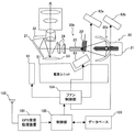
図6は、プロジェクタ1の構成を示すブロック図である。
図6に示すように、制御手段としての制御部100は、演算手段たるCPU(Central Processing Unit)、記憶手段たるRAM(Random Access Memory)、RAM(Read Only Memory)などを有している。プロジェクタ全体の制御を司る制御部100には、様々な構成機器が通信可能に電気的に接続されている。位置情報取得手段としてのGPS受信処理装置101は、GPSアンテナ102によって衛星からの電波(GPS信号)を受信し、受信したGPS信号を元に位置情報(測位データ(経度、緯度))を検出する。制御部100は、位置情報をもとに記憶手段としてのデータベース103を参照する。プロジェクタ1が設置されている場所に対応する定格電源電圧と標高情報とを読み出す。その定格電源電圧と標高情報とに応じて、冷却手段が制御される。これにより、定格電源電圧を検出する検出回路を設けることなく、定格電源電圧の相違と標高情報の相違とに応じて最適に冷却手段を制御することができる。よって、発熱源に対する冷却効果を向上させることができる。なお、データベース103には、予め、国、住所など毎の定格電源電圧、標高情報(高度)、定格電源電圧や標高情報に対応した冷却効果の過不足ない各ファンの回転数、言語に対応する国(地域)や住所に関する情報等が記憶されている。
FIG. 6 is a block diagram showing the configuration of the
As shown in FIG. 6, the
以上により、GPS信号を元に位置情報を取得してその位置情報よりデータベースを参照して定格電源電圧と標高情報とを得、地域によっては冷却ファンの回転数を低く抑えて静音化を図ることが可能になる。なお、本実施形態の冷却装置は、制御部100、GPS受信処理装置101、GPSアンテナ102、データベース103及びファン制御部104を備えている。また、プロジェクタ近傍にいる操作者の所持する携帯電話機が取得した位置情報を受信することでもプロジェクタ1の位置情報を取得することができる。
As described above, the position information is acquired based on the GPS signal, the rated power supply voltage and the altitude information are obtained by referring to the database from the position information, and in some areas, the rotation speed of the cooling fan is kept low and the noise is reduced. Is possible. Note that the cooling device of this embodiment includes a
そして、ファン制御部104は、それらの情報を元に吸気ファン61、排気ファン62a,62b、遠心力ファン63のそれぞれの回転数を制御する。具体的には、吸気ファン61、排気ファン63a,63b及び遠心力ファン63には、それぞれ回転数を検知する回転数検知センサが設けられている。ファン制御部104は、これらの回転数検知センサの検知結果に基づいて、過不足のない冷却効果が得られる設定回転数となるように、吸気ファン61、排気ファン63a,63b及び遠心力ファン63の駆動を制御している。
The
なお、手入力可能であり、あるいはモニタなどの表示部に表示されたリストから選択可能な入力手段を備え、国、住所、言語等の情報を手入力したり、表示部に表示された国、住所、言語等のリストから選択したりすることも可能である。よって、衛星や携帯電話からの電波を受信する受信手段を備えていなくても、入力された情報に基づいて位置情報を取得して、その位置情報をもとにデータベースよりプロジェクタ1が設置されている場所の定格電源電圧と高所情報とを取得することができる。これにより、低コスト化が図れる。
In addition, it is possible to input manually or provide an input means that can be selected from a list displayed on a display unit such as a monitor, and manually input information such as country, address, language, etc., or a country displayed on the display unit, It is also possible to select from a list of addresses, languages, etc. Therefore, even if no receiving means for receiving radio waves from a satellite or a mobile phone is provided, the position information is acquired based on the input information, and the
以上に説明したものは一例であり、次の態様毎に特有の効果を奏する。
(態様A)
電源ユニット51等の発熱源を冷却する吸気ファン61等の冷却手段と、該冷却手段を制御するファン制御部104等の制御手段とを備えた冷却装置において、前記発熱源の設置場所の位置情報を取得するGPS受信処理装置101等の位置情報取得手段と、位置情報に対応する定格電源電圧と標高情報とを記憶するデータベース103等の記憶手段とを備え、前記制御手段は、前記位置情報取得手段によって取得した位置情報をもとに前記記憶手段を参照して得られた前記定格電源電圧と前記標高情報とに応じて、前記冷却手段を制御する。
本態様によれば、従来例において発熱源の設置場所の標高情報を得るために取得した位置情報を用いて定格電源電圧も検出できている。具体的には、記憶手段には、位置情報に対応する定格電源電圧と標高情報とが記憶されている。そして、位置情報取得手段によって取得した位置情報をもとに記憶手段を参照し、その位置情報に対応する定格電源電圧と標高情報とを当該記憶手段より読み出して取得する。その定格電源電圧と標高情報とに応じて、冷却手段が制御される。これにより、定格電源電圧を検出する検出回路を設けることなく、定格電源電圧の相違と標高情報の相違とに応じて最適に冷却手段を制御することができる。よって、発熱源に対する冷却効果を向上させることができる。
What was demonstrated above is an example, and there exists an effect peculiar for every following aspect.
(Aspect A)
In a cooling device comprising a cooling means such as an
According to this aspect, the rated power supply voltage can also be detected using the position information acquired in order to obtain the altitude information of the installation location of the heat source in the conventional example. Specifically, the rated power supply voltage and altitude information corresponding to the position information are stored in the storage means. Then, the storage means is referred to based on the position information acquired by the position information acquisition means, and the rated power supply voltage and altitude information corresponding to the position information are read from the storage means and acquired. The cooling means is controlled according to the rated power supply voltage and altitude information. Thereby, the cooling means can be optimally controlled according to the difference in the rated power supply voltage and the difference in the altitude information without providing a detection circuit for detecting the rated power supply voltage. Therefore, the cooling effect for the heat generation source can be improved.
(態様B)
(態様A)において、前記位置情報取得手段は、衛星から送られる電波から取得した前記発熱源の設置場所の位置情報を取得する。
本態様によれば、発熱源の設置場所の位置を高精度に検知することができる。
(Aspect B)
In (Aspect A), the position information acquisition unit acquires the position information of the installation location of the heat source acquired from radio waves transmitted from a satellite.
According to this aspect, the position of the installation location of the heat source can be detected with high accuracy.
(態様C)
(態様A)において、前記位置情報取得手段は、前記発熱源近傍にある携帯電話機が取得した位置情報を受信して前記発熱源の設置場所の位置情報を取得する。
本態様によれば、発熱源の周囲にいる操作者が持っている携帯電話が取得した位置情報を受信することで、衛星からの電波を受信することができなくても発熱源の設置場所の位置情報を所得することができる。よって、最適な冷却手段の制御を安定して行うことができる。
(Aspect C)
In (Aspect A), the position information acquisition unit receives position information acquired by a mobile phone in the vicinity of the heat generation source, and acquires position information of an installation location of the heat generation source.
According to this aspect, by receiving the position information acquired by the mobile phone held by the operator around the heat source, even if the radio wave from the satellite cannot be received, the location of the heat source is determined. You can earn location information. Therefore, optimal control of the cooling means can be stably performed.
(態様D)
(態様A)〜(態様C)において、言語、高度、国、住所を入力する入力手段を備え、前記位置情報取得手段は、該入力手段によって入力された言語、高度、国、住所により位置情報を取得する。
本態様によれば、衛星や携帯電話からの電波を受信する受信手段を備えていなくても、入力手段によって入力された言語、高度、国、住所により発熱源の設置場所の位置情報を取得することができる。よって、高価な受信手段を備えないでよいので、低コスト化につながる。
(Aspect D)
In (Aspect A) to (Aspect C), an input means for inputting a language, altitude, country, and address is provided, and the position information acquisition means is position information based on the language, altitude, country, and address input by the input means. To get.
According to this aspect, even if no receiving means for receiving radio waves from a satellite or a mobile phone is provided, the position information of the installation location of the heat generation source is acquired by the language, altitude, country, and address input by the input means. be able to. Therefore, it is not necessary to provide expensive receiving means, leading to cost reduction.
(態様E)
(態様A)〜(態様D)において、前記冷却手段は吸気ファン61等の冷却ファンであり、前記制御手段は、前記定格電源電圧が低い場合は前記冷却ファンの回転数を上げ、前記定格電源電圧が高い場合は前記冷却ファンの回転数を下げるよう、前記冷却ファンの駆動を制御する。
本態様によれば、定格電源電圧が低いと発熱源の発熱量が上がるので、このときは冷却ファンの回転数を上げて冷却効果を高める。一方、定格電源電圧が高いと発熱源の発熱量は下がるので、このときは冷却ファンの回転数を下げて過度な冷却効果を抑制し、かつ、冷却ファンによる騒音を抑制できる。
(Aspect E)
In (Aspect A) to (Aspect D), the cooling means is a cooling fan such as an
According to this aspect, if the rated power supply voltage is low, the heat generation amount of the heat generation source increases, and at this time, the cooling effect is increased by increasing the number of revolutions of the cooling fan. On the other hand, if the rated power supply voltage is high, the amount of heat generated by the heat generation source is reduced. At this time, the number of rotations of the cooling fan can be lowered to suppress an excessive cooling effect, and noise from the cooling fan can be suppressed.
(態様F)
(態様A)〜(態様E)において、前記冷却手段は冷却ファンであり、前記制御手段は、前記発熱源の設置場所の高度が高い場合は前記冷却ファンの回転数を上げ、前記発熱源の設置場所の高度が低い場合は前記冷却ファンの回転数を下げるよう、前記冷却ファンの駆動を制御する。
本態様によれば、発熱源の設置場所の高度が高い場合は、気圧が下がり空気の密度が下がって冷却効率が下がるので、このときは冷却ファンの回転数を上げて冷却効果を高める。一方、発熱源の設置場所の高度が低い場合は冷却ファンの回転数を下げて過度な冷却効果にならないようにできる。これにより、過不足のない冷却効果が得られる。
(Aspect F)
In (Aspect A) to (Aspect E), the cooling means is a cooling fan, and the control means increases the number of rotations of the cooling fan when the installation location of the heat generation source is high. When the altitude of the installation place is low, the driving of the cooling fan is controlled so as to reduce the rotation speed of the cooling fan.
According to this aspect, when the altitude of the installation location of the heat generation source is high, the atmospheric pressure is lowered and the density of the air is lowered to lower the cooling efficiency. At this time, the cooling effect is increased by increasing the rotation speed of the cooling fan. On the other hand, when the altitude of the installation location of the heat source is low, the cooling fan speed can be lowered to prevent an excessive cooling effect. Thereby, the cooling effect without excess and deficiency is acquired.
(態様G)
放電ランプ21等の光源と、冷却対象を冷却する冷却手段と、前記光源の光を用いて画像を投射するプロジェクタ1等の画像投射装置において、前記冷却手段として、(態様A)〜(態様F)のいずれか1項に記載の冷却装置を用いたことを特徴とする。
本態様によれば、適切な使用温度範囲で光源を安定して駆動させることができるので、安定した画質を提供できる。
(Aspect G)
In the image projection apparatus such as the
According to this aspect, since the light source can be stably driven in an appropriate operating temperature range, stable image quality can be provided.
1 プロジェクタ
11 操作部
12 ズームレバー
13 電源スイッチ
14 外部入力端子
15 投射レンズ
16 センサ
17 吸気口
18 排気口
20 光源部
20a 光源ユニット
20b 画像照明光学系
21 放電ランプ
22 カラーホイール
23 ライトトンネル
24 リレーレンズ
30 画像生成部
31 平面ミラー
32 凹面ミラー
33 DMD
40 投射光学部
61 吸気ファン
62a 排気ファン
62b 排気ファン
63 遠心力ファン
100 制御部
101 GPS受信処理装置
102 GPSアンテナ
103 データベース
104 ファン制御部
200 スクリーン
DESCRIPTION OF
40 Projection
Claims (7)
前記発熱源の設置場所の位置情報を取得する位置情報取得手段と、
位置情報に対応する定格電源電圧と標高情報とを記憶する記憶手段とを備え、
前記制御手段は、前記位置情報取得手段によって取得した位置情報をもとに前記記憶手段を参照して得られた前記定格電源電圧と前記標高情報とに応じて、前記冷却手段を制御することを特徴する冷却装置。 In a cooling device comprising a cooling means for cooling a heat source and a control means for controlling the cooling means,
Position information acquisition means for acquiring position information of an installation location of the heat source;
Storage means for storing rated power supply voltage and altitude information corresponding to the position information;
The control means controls the cooling means according to the rated power supply voltage and the altitude information obtained by referring to the storage means based on the position information acquired by the position information acquisition means. Characteristic cooling system.
前記位置情報取得手段は、衛星から送られる電波から取得した前記発熱源の設置場所の位置情報を取得することを特徴とする冷却装置。 The cooling device according to claim 1, wherein
The cooling apparatus according to claim 1, wherein the position information acquisition unit acquires position information of an installation location of the heat source acquired from radio waves transmitted from a satellite.
前記位置情報取得手段は、前記発熱源近傍にある携帯電話機が取得した位置情報を受信して前記発熱源の設置場所の位置情報を取得することを特徴とする冷却装置。 The cooling device according to claim 1, wherein
The cooling apparatus according to claim 1, wherein the position information acquisition unit receives position information acquired by a mobile phone in the vicinity of the heat source and acquires position information of an installation location of the heat source.
言語、高度、国、住所を入力する入力手段を備え、前記位置情報取得手段は、該入力手段によって入力された言語、高度、国、住所により位置情報を取得することを特徴とする冷却装置。 In the cooling device according to any one of claims 1 to 3,
A cooling apparatus comprising input means for inputting a language, altitude, country, and address, wherein the position information acquisition means acquires position information based on the language, altitude, country, and address input by the input means.
前記冷却手段は冷却ファンであり、前記制御手段は、前記定格電源電圧が低い場合は前記冷却ファンの回転数を上げ、前記定格電源電圧が高い場合は前記冷却ファンの回転数を下げるよう、前記冷却ファンの駆動を制御することを特徴とする冷却装置。 In the cooling device according to any one of claims 1 to 4,
The cooling means is a cooling fan, and the control means increases the rotation speed of the cooling fan when the rated power supply voltage is low, and decreases the rotation speed of the cooling fan when the rated power supply voltage is high. A cooling device that controls driving of a cooling fan.
前記冷却手段は冷却ファンであり、前記制御手段は、前記発熱源の設置場所の高度が高い場合は前記冷却ファンの回転数を上げ、前記発熱源の設置場所の高度が低い場合は前記冷却ファンの回転数を下げるよう、前記冷却ファンの駆動を制御することを特徴とする冷却装置。 In the cooling device according to any one of claims 1 to 5,
The cooling means is a cooling fan, and the control means increases the number of rotations of the cooling fan when the altitude of the installation location of the heat source is high, and the cooling fan when the altitude of the installation location of the heat generation source is low. A cooling device that controls driving of the cooling fan so as to reduce the rotation speed of the cooling fan.
前記冷却手段として、請求項1〜6のいずれか1項に記載の冷却装置を用いたことを特徴とする画像投射装置。 In an image projection device that projects an image using a light source, cooling means for cooling an object to be cooled, and light from the light source,
An image projection apparatus using the cooling device according to claim 1 as the cooling means.
Priority Applications (1)
| Application Number | Priority Date | Filing Date | Title |
|---|---|---|---|
| JP2015121846A JP2017009645A (en) | 2015-06-17 | 2015-06-17 | Cooling device and image projection device including the same |
Applications Claiming Priority (1)
| Application Number | Priority Date | Filing Date | Title |
|---|---|---|---|
| JP2015121846A JP2017009645A (en) | 2015-06-17 | 2015-06-17 | Cooling device and image projection device including the same |
Publications (1)
| Publication Number | Publication Date |
|---|---|
| JP2017009645A true JP2017009645A (en) | 2017-01-12 |
Family
ID=57763332
Family Applications (1)
| Application Number | Title | Priority Date | Filing Date |
|---|---|---|---|
| JP2015121846A Pending JP2017009645A (en) | 2015-06-17 | 2015-06-17 | Cooling device and image projection device including the same |
Country Status (1)
| Country | Link |
|---|---|
| JP (1) | JP2017009645A (en) |
Cited By (1)
| Publication number | Priority date | Publication date | Assignee | Title |
|---|---|---|---|---|
| CN111819515A (en) * | 2018-04-13 | 2020-10-23 | 惠普发展公司,有限责任合伙企业 | Thermal strategy for fan control |
-
2015
- 2015-06-17 JP JP2015121846A patent/JP2017009645A/en active Pending
Cited By (2)
| Publication number | Priority date | Publication date | Assignee | Title |
|---|---|---|---|---|
| CN111819515A (en) * | 2018-04-13 | 2020-10-23 | 惠普发展公司,有限责任合伙企业 | Thermal strategy for fan control |
| CN111819515B (en) * | 2018-04-13 | 2023-09-08 | 惠普发展公司,有限责任合伙企业 | Thermal strategies for fan control |
Similar Documents
| Publication | Publication Date | Title |
|---|---|---|
| US7889324B2 (en) | Distance measuring system and projector | |
| JP4692531B2 (en) | Projector and optical distance measuring method. | |
| US9726965B2 (en) | Projection device, image correction method, and computer-readable recording medium | |
| US9666109B2 (en) | Projector | |
| US8002416B2 (en) | Distance measuring device and projector including same distance measuring device | |
| US10230930B2 (en) | Image projection apparatus | |
| US20080239246A1 (en) | Projector | |
| JP4582264B1 (en) | Projection display | |
| JP2016224335A (en) | Light source device and projection device | |
| US11019314B2 (en) | Projector and method for controlling projector | |
| JP2012003257A (en) | Projection type image display apparatus | |
| US20150030316A1 (en) | Signal determination apparatus, optical projection apparatus, signal determination method, and storage meidum | |
| JP2016051121A (en) | Projection optical device and image projection device | |
| JP2017009645A (en) | Cooling device and image projection device including the same | |
| JP2015222299A (en) | Light source device and projection device | |
| JP2009186816A (en) | Electrical equipment | |
| JP2009063671A (en) | projector | |
| JP2015011272A (en) | Projection optical device and image projection device | |
| US9395607B2 (en) | Image projection apparatus including a shield | |
| JP2015025872A (en) | Image projection device, and control method of image projection device | |
| WO2013176005A1 (en) | Projection device, image correction method, and program | |
| JP2014123028A (en) | Optical element fixing device, projector including the optical element fixing device, and angle adjustment method of optical element by the optical element fixing device | |
| JP2003207847A (en) | Image display device and deflection device | |
| JP2003207846A (en) | Image display device, deflection device and image display system | |
| JP2015022020A (en) | Projection optical device and image projection device |