JP2017010696A - Induction heating apparatus and power generation system - Google Patents
Induction heating apparatus and power generation system Download PDFInfo
- Publication number
- JP2017010696A JP2017010696A JP2015123352A JP2015123352A JP2017010696A JP 2017010696 A JP2017010696 A JP 2017010696A JP 2015123352 A JP2015123352 A JP 2015123352A JP 2015123352 A JP2015123352 A JP 2015123352A JP 2017010696 A JP2017010696 A JP 2017010696A
- Authority
- JP
- Japan
- Prior art keywords
- heating
- heat
- heating unit
- induction heating
- heat medium
- Prior art date
- Legal status (The legal status is an assumption and is not a legal conclusion. Google has not performed a legal analysis and makes no representation as to the accuracy of the status listed.)
- Pending
Links
- 238000010438 heat treatment Methods 0.000 title claims abstract description 351
- 230000006698 induction Effects 0.000 title claims abstract description 113
- 238000010248 power generation Methods 0.000 title claims abstract description 44
- 230000004907 flux Effects 0.000 claims abstract description 80
- 238000007599 discharging Methods 0.000 abstract 1
- XLYOFNOQVPJJNP-UHFFFAOYSA-N water Substances O XLYOFNOQVPJJNP-UHFFFAOYSA-N 0.000 description 27
- 238000012546 transfer Methods 0.000 description 18
- 239000011810 insulating material Substances 0.000 description 13
- 230000008859 change Effects 0.000 description 8
- 229910001338 liquidmetal Inorganic materials 0.000 description 8
- 230000020169 heat generation Effects 0.000 description 7
- 239000000463 material Substances 0.000 description 7
- 238000013021 overheating Methods 0.000 description 7
- XEEYBQQBJWHFJM-UHFFFAOYSA-N Iron Chemical compound [Fe] XEEYBQQBJWHFJM-UHFFFAOYSA-N 0.000 description 6
- 238000005338 heat storage Methods 0.000 description 5
- 230000004048 modification Effects 0.000 description 5
- 238000012986 modification Methods 0.000 description 5
- 230000002093 peripheral effect Effects 0.000 description 5
- 206010037660 Pyrexia Diseases 0.000 description 4
- 150000003839 salts Chemical class 0.000 description 4
- RYGMFSIKBFXOCR-UHFFFAOYSA-N Copper Chemical compound [Cu] RYGMFSIKBFXOCR-UHFFFAOYSA-N 0.000 description 3
- 230000000694 effects Effects 0.000 description 3
- 229910052742 iron Inorganic materials 0.000 description 3
- 238000004519 manufacturing process Methods 0.000 description 3
- 229910052751 metal Inorganic materials 0.000 description 3
- 239000002184 metal Substances 0.000 description 3
- 229910045601 alloy Inorganic materials 0.000 description 2
- 239000000956 alloy Substances 0.000 description 2
- 229910052782 aluminium Inorganic materials 0.000 description 2
- XAGFODPZIPBFFR-UHFFFAOYSA-N aluminium Chemical compound [Al] XAGFODPZIPBFFR-UHFFFAOYSA-N 0.000 description 2
- 239000004918 carbon fiber reinforced polymer Substances 0.000 description 2
- 239000004020 conductor Substances 0.000 description 2
- 229910052802 copper Inorganic materials 0.000 description 2
- 239000010949 copper Substances 0.000 description 2
- 230000007423 decrease Effects 0.000 description 2
- 239000011152 fibreglass Substances 0.000 description 2
- 239000008236 heating water Substances 0.000 description 2
- 239000000696 magnetic material Substances 0.000 description 2
- 238000000034 method Methods 0.000 description 2
- 229910000838 Al alloy Inorganic materials 0.000 description 1
- DGAQECJNVWCQMB-PUAWFVPOSA-M Ilexoside XXIX Chemical compound C[C@@H]1CC[C@@]2(CC[C@@]3(C(=CC[C@H]4[C@]3(CC[C@@H]5[C@@]4(CC[C@@H](C5(C)C)OS(=O)(=O)[O-])C)C)[C@@H]2[C@]1(C)O)C)C(=O)O[C@H]6[C@@H]([C@H]([C@@H]([C@H](O6)CO)O)O)O.[Na+] DGAQECJNVWCQMB-PUAWFVPOSA-M 0.000 description 1
- 229910000861 Mg alloy Inorganic materials 0.000 description 1
- 229910000831 Steel Inorganic materials 0.000 description 1
- 238000013459 approach Methods 0.000 description 1
- 230000008901 benefit Effects 0.000 description 1
- 238000009835 boiling Methods 0.000 description 1
- 239000011449 brick Substances 0.000 description 1
- 239000000919 ceramic Substances 0.000 description 1
- 238000002485 combustion reaction Methods 0.000 description 1
- 239000002131 composite material Substances 0.000 description 1
- 238000001816 cooling Methods 0.000 description 1
- 230000007797 corrosion Effects 0.000 description 1
- 238000005260 corrosion Methods 0.000 description 1
- 238000010586 diagram Methods 0.000 description 1
- 238000009826 distribution Methods 0.000 description 1
- 238000005516 engineering process Methods 0.000 description 1
- -1 for example Substances 0.000 description 1
- 239000007789 gas Substances 0.000 description 1
- 239000011491 glass wool Substances 0.000 description 1
- 230000006872 improvement Effects 0.000 description 1
- 239000012774 insulation material Substances 0.000 description 1
- 239000007788 liquid Substances 0.000 description 1
- 230000007774 longterm Effects 0.000 description 1
- 230000007246 mechanism Effects 0.000 description 1
- 238000002844 melting Methods 0.000 description 1
- 230000008018 melting Effects 0.000 description 1
- 150000002739 metals Chemical class 0.000 description 1
- 239000011490 mineral wool Substances 0.000 description 1
- 239000004033 plastic Substances 0.000 description 1
- 229920003023 plastic Polymers 0.000 description 1
- 238000004904 shortening Methods 0.000 description 1
- 229910052708 sodium Inorganic materials 0.000 description 1
- 239000011734 sodium Substances 0.000 description 1
- 239000010935 stainless steel Substances 0.000 description 1
- 229910001220 stainless steel Inorganic materials 0.000 description 1
- 239000010959 steel Substances 0.000 description 1
- 238000003860 storage Methods 0.000 description 1
- 239000011232 storage material Substances 0.000 description 1
- 238000009834 vaporization Methods 0.000 description 1
- 230000008016 vaporization Effects 0.000 description 1
- 238000003466 welding Methods 0.000 description 1
Images




Classifications
-
- Y—GENERAL TAGGING OF NEW TECHNOLOGICAL DEVELOPMENTS; GENERAL TAGGING OF CROSS-SECTIONAL TECHNOLOGIES SPANNING OVER SEVERAL SECTIONS OF THE IPC; TECHNICAL SUBJECTS COVERED BY FORMER USPC CROSS-REFERENCE ART COLLECTIONS [XRACs] AND DIGESTS
- Y02—TECHNOLOGIES OR APPLICATIONS FOR MITIGATION OR ADAPTATION AGAINST CLIMATE CHANGE
- Y02E—REDUCTION OF GREENHOUSE GAS [GHG] EMISSIONS, RELATED TO ENERGY GENERATION, TRANSMISSION OR DISTRIBUTION
- Y02E10/00—Energy generation through renewable energy sources
- Y02E10/70—Wind energy
- Y02E10/72—Wind turbines with rotation axis in wind direction
Landscapes
- Wind Motors (AREA)
- General Induction Heating (AREA)
Abstract
Description
本発明は、誘導加熱を利用して熱媒体を加熱する誘導加熱装置、及びそれを備える発電システムに関する。特に、加熱部で発生した熱を、流通路を流通する熱媒体に効率よく伝熱できるアキシャルギャップ型の誘導加熱装置に関する。 The present invention relates to an induction heating apparatus that heats a heat medium using induction heating, and a power generation system including the induction heating apparatus. In particular, the present invention relates to an axial gap type induction heating apparatus capable of efficiently transferring heat generated in a heating section to a heat medium flowing through a flow passage.
水を加熱する装置として、誘導加熱(渦電流)を利用した加熱装置が提案されている(例えば、特許文献1参照)。特許文献1に記載の渦電流加熱装置は、外周に永久磁石が配置された回転可能なロータと、このロータの外側に固定して設けられ、内部に水を流通させる流通路が形成された導電材料の加熱部とを備える。そして、ロータが回転することにより、ロータ外周の永久磁石による磁力線(磁束)が加熱部を貫通して移動することで、加熱部に渦電流が発生して、加熱部が発熱する。その結果、加熱部で発生した熱が内部の流通路を流通する水に伝達され、水が加熱される。 As a device for heating water, a heating device using induction heating (eddy current) has been proposed (for example, see Patent Document 1). The eddy current heating device described in Patent Document 1 is a conductive rotor having a rotatable rotor having a permanent magnet arranged on the outer periphery and a fixed passage provided outside the rotor, and a flow passage through which water flows. A heating part for the material. Then, when the rotor rotates, the magnetic lines of force (magnetic flux) generated by the permanent magnets on the outer periphery of the rotor move through the heating unit, so that an eddy current is generated in the heating unit and the heating unit generates heat. As a result, the heat generated in the heating unit is transmitted to the water flowing through the internal flow passage, and the water is heated.
上記の技術は風力などのエネルギーを利用して給湯を行うことを主目的としたものである。最近では、誘導加熱装置により加熱した熱媒体の熱を電気エネルギーに変換する発電システムが提案されている(例えば、特許文献2,3参照)。特許文献2,3には、回転体と、回転体の外周に設けられて回転体の径方向に磁束を発生する磁束発生部と、回転体の外側に回転体と間隔をあけて配置される筒状の加熱部と、加熱部に設けられ、熱媒体が流通する流通路(配管)とを備える誘導加熱装置が開示されている。特許文献2,3では、加熱部の軸方向に沿って複数の流通路を形成し、流通路の一端側から熱媒体を供給し、他端側から排出する構成とすることが例示されている。 The above-described technology is mainly intended to supply hot water using energy such as wind power. Recently, a power generation system that converts heat of a heat medium heated by an induction heating device into electric energy has been proposed (see, for example, Patent Documents 2 and 3). In Patent Documents 2 and 3, a rotating body, a magnetic flux generating section that is provided on the outer periphery of the rotating body and generates a magnetic flux in the radial direction of the rotating body, and arranged outside the rotating body with a gap from the rotating body. An induction heating apparatus is disclosed that includes a cylindrical heating unit and a flow passage (pipe) that is provided in the heating unit and through which a heat medium flows. Patent Documents 2 and 3 exemplify a configuration in which a plurality of flow paths are formed along the axial direction of the heating unit, a heat medium is supplied from one end side of the flow path, and discharged from the other end side. .
上述した特許文献1〜3に記載の誘導加熱装置はいずれも、回転体(磁束発生部)と加熱部とが径方向に間隔をあけて対向して配置された、所謂ラジアルギャップ型の構造である。一方で、回転体(磁束発生部)と加熱部とが軸方向に間隔をあけて対向して配置された、所謂アキシャルギャップ型の誘導加熱装置は、これまであまり提案されていない。 Each of the induction heating devices described in Patent Documents 1 to 3 described above has a so-called radial gap type structure in which a rotating body (magnetic flux generation unit) and a heating unit are arranged to face each other with a gap in the radial direction. is there. On the other hand, a so-called axial gap type induction heating apparatus in which a rotating body (magnetic flux generating section) and a heating section are arranged to face each other with an interval in the axial direction has not been proposed so far.
また、誘導加熱装置では、加熱部で発生した熱を、流通路を流通する熱媒体に効率よく伝熱することが望まれる。しかし、アキシャルギャップ型の場合に、加熱部で発生した熱を受け取る熱媒体の流通路の構成について、必ずしも十分な検討がなされているとは言えないのが実情である。 In addition, in the induction heating apparatus, it is desired that the heat generated in the heating unit is efficiently transferred to the heat medium flowing through the flow path. However, in the case of the axial gap type, in reality, it cannot be said that sufficient studies have been made on the configuration of the flow path of the heat medium that receives the heat generated in the heating section.
本発明は上記事情に鑑みてなされたものであり、本発明の目的の一つは、加熱部で発生した熱を、流通路を流通する熱媒体に効率よく伝熱できるアキシャルギャップ型の誘導加熱装置を提供することにある。また、本発明の別の目的は、上記誘導加熱装置を備える発電システムを提供することにある。 The present invention has been made in view of the above circumstances, and one of the objects of the present invention is an axial gap type induction heating capable of efficiently transferring heat generated in the heating section to a heat medium flowing through the flow passage. To provide an apparatus. Another object of the present invention is to provide a power generation system including the induction heating device.
本発明の一態様に係る誘導加熱装置は、熱媒体を加熱する誘導加熱装置であって、回転軸を有する板状の回転体と、前記回転体に対して軸方向に間隔をあけて対向して配置される板状の加熱部と、前記回転体の前記加熱部に対向する対向面に設けられ、前記加熱部に対して磁束を発生する磁束発生部と、前記加熱部の径方向に設けられ、前記熱媒体が流通する流通路と、を備える。前記流通路は、前記加熱部の径方向の外側に前記熱媒体を供給する入口部と、その径方向の内側に前記熱媒体を排出する出口部と、を有する。 An induction heating apparatus according to an aspect of the present invention is an induction heating apparatus that heats a heat medium, and is opposed to a plate-shaped rotating body having a rotating shaft, with an axial interval between the rotating body and the rotating body. A plate-shaped heating unit disposed on the opposite surface of the rotating body facing the heating unit, and a magnetic flux generation unit that generates a magnetic flux with respect to the heating unit, and a radial direction of the heating unit. And a flow passage through which the heat medium flows. The flow path includes an inlet portion that supplies the heat medium to the outer side in the radial direction of the heating unit, and an outlet portion that discharges the heat medium to the inner side in the radial direction.
本発明の一態様に係る発電システムは、上記本発明の一態様に係る誘導加熱装置と、前記誘導加熱装置により加熱した前記熱媒体の熱を電気エネルギーに変換する発電部と、を備える。 The power generation system which concerns on 1 aspect of this invention is provided with the induction heating apparatus which concerns on the said 1 aspect of this invention, and the electric power generation part which converts the heat | fever of the said heat medium heated with the said induction heating apparatus into electrical energy.
上記誘導加熱装置は、アキシャルギャップ型の構造を有し、加熱部で発生した熱を、流通路を流通する熱媒体に効率よく伝熱できる。上記発電システムは、誘導加熱装置における熱媒体への熱交換効率を改善でき、発電効率の向上を図ることが可能である。 The induction heating device has an axial gap type structure, and can efficiently transfer heat generated in the heating unit to a heat medium flowing through the flow passage. The power generation system can improve the efficiency of heat exchange with the heat medium in the induction heating device, and can improve the power generation efficiency.
[本発明の実施形態の説明]
本発明者は、板状の回転体と加熱部とが互いに対向して配置され、回転体の加熱部に対向する対向面に磁束発生部が設けられたアキシャルギャップ型の誘導加熱装置において、加熱部から熱を受け取る熱媒体の流通路の構成について鋭意検討した。具体的には、加熱部での発熱量の分布、及び加熱部から熱媒体への熱の伝わり方について検討し、加熱部で発生した熱を熱媒体に効率よく伝熱できる流通路の構成について検討した。
[Description of Embodiment of the Present Invention]
The inventor of the present invention provides an axial gap type induction heating apparatus in which a plate-shaped rotating body and a heating unit are arranged to face each other, and a magnetic flux generation unit is provided on an opposing surface facing the heating unit of the rotating body. The structure of the flow path of the heat medium that receives heat from the section was studied earnestly. Specifically, we examined the distribution of the amount of heat generated in the heating unit and how heat is transferred from the heating unit to the heating medium, and the configuration of the flow path that can efficiently transfer the heat generated in the heating unit to the heating medium. investigated.
変動磁束が通過する導体内において、誘導加熱(渦電流)による発熱量は、磁場強度、磁場の変化速度(周波数)の大きさに比例して増加することが知られている。アキシャルギャップ型の誘導加熱装置の場合、回転体の径方向の外側では内側よりも周速が速くなるため、加熱部を通過する磁束発生部による磁束の変化速度は外側の方が大きくなる。そのため、同じ磁場強度であっても、加熱部の径方向の外側の方が発熱量が大きく、内側ほど発熱量が小さくなる。 It is known that the amount of heat generated by induction heating (eddy current) increases in proportion to the strength of the magnetic field and the rate of change (frequency) of the magnetic field in the conductor through which the varying magnetic flux passes. In the case of the axial gap type induction heating device, the outer peripheral speed of the rotating body is higher than the inner peripheral speed than the inner side, so that the rate of change of the magnetic flux by the magnetic flux generating section passing through the heating section is greater on the outer side. Therefore, even if the magnetic field strength is the same, the heat generation amount is larger on the outer side in the radial direction of the heating unit, and the heat generation amount is smaller on the inner side.
また、流通路は、加熱部に沿って設け、加熱部に沿う方向の一方側から他方側へ熱媒体が流通するように構成することが考えられる。熱媒体は、加熱部から熱を順次受け取りながら流通路を流れることにより、徐々に加熱される。よって、熱媒体の温度は、流通路の入口部側(入口部又はその近傍)よりも出口部側の方が高く、出口部側(出口部又はその近傍)では加熱部の温度に近付く又は等しくなる。 Further, it is conceivable that the flow path is provided along the heating unit and configured so that the heat medium flows from one side to the other side in the direction along the heating unit. The heat medium is gradually heated by flowing through the flow path while sequentially receiving heat from the heating unit. Therefore, the temperature of the heat medium is higher on the outlet side than on the inlet side (inlet part or the vicinity thereof) of the flow passage, and approaches or equals the temperature of the heating part on the outlet side (the outlet part or its vicinity). Become.
ここで、加熱部と熱媒体との間の熱伝達率h(W/m2・K)は、次式で定義される。
h=Q/[A(Tw−Ta)]=J/(Tw−Ta)
Q:熱移動量(W)
J:熱流束密度(W/m2)
A:伝熱面積(m2)
Tw:加熱部表面の温度(K)
Ta:熱媒体の温度(K)
但し、Tw>Taとする。
Here, the heat transfer coefficient h (W / m 2 · K) between the heating unit and the heat medium is defined by the following equation.
h = Q / [A (Tw-Ta)] = J / (Tw-Ta)
Q: Heat transfer amount (W)
J: Heat flux density (W / m 2 )
A: Heat transfer area (m 2 )
Tw: Temperature of the heated part surface (K)
Ta: Temperature of heat medium (K)
However, Tw> Ta.
上記式から、加熱部と熱媒体との間の熱移動量Qは、加熱部と熱媒体との温度差(Tw−Ta)を大きくしたり、伝熱面積Aを大きくするほど増大することが分かる。そのため、流通路の入口部側では、熱媒体の温度が低く、加熱部と流通路に流れる熱媒体との温度差が大きいことから、熱移動量が大きくなる。一方、出口部側では、熱媒体の温度が高く、加熱部と熱媒体との温度差が小さいので、熱移動量が小さくなる。つまり、流通路の入口部側では、熱移動量が大きく、加熱部から熱媒体へ十分に伝熱されるが、流通路の出口部側では、熱移動量が小さくなるため、加熱部から熱媒体へ十分に伝熱されない場合がある。したがって、流通路の構成によっては、加熱部で発生した熱を、流通路を流通する熱媒体に効率よく伝熱できないことが考えられる。また、加熱部で発生した熱を熱媒体によって十分に抜熱できず、最悪の場合、加熱部が過熱により溶解するなど損傷することも考えられる。そこで、加熱部に設けられた流通路の径を大きくするなど、全体的に伝熱面積を大きくすることで、加熱部と熱媒体との間の熱移動量を増やすことが考えられるが、その場合、装置の大型化やコストアップを招く。 From the above equation, the heat transfer amount Q between the heating unit and the heat medium increases as the temperature difference (Tw−Ta) between the heating unit and the heat medium increases or the heat transfer area A increases. I understand. Therefore, on the inlet portion side of the flow passage, the temperature of the heat medium is low, and the temperature difference between the heating unit and the heat medium flowing through the flow passage is large, so the amount of heat transfer is large. On the other hand, on the exit side, the temperature of the heat medium is high and the temperature difference between the heating part and the heat medium is small, so the amount of heat transfer is small. In other words, the amount of heat transfer is large on the inlet side of the flow passage, and heat is sufficiently transferred from the heating unit to the heat medium. There may be insufficient heat transfer. Therefore, depending on the configuration of the flow path, it is conceivable that the heat generated in the heating unit cannot be efficiently transferred to the heat medium flowing through the flow path. Further, the heat generated in the heating unit cannot be sufficiently removed by the heat medium, and in the worst case, the heating unit may be damaged due to overheating. Therefore, it is conceivable to increase the amount of heat transfer between the heating unit and the heat medium by increasing the overall heat transfer area, such as increasing the diameter of the flow path provided in the heating unit. In this case, the apparatus is increased in size and cost.
本発明者は、アキシャルギャップ型の誘導加熱装置において、熱媒体の流通路を加熱部の径方向に設けると共に、加熱部の径方向に外側に流通路の入口部を、その径方向の内側に流通路の出口部を設けることを提案する。以下、本発明の実施態様を列記して説明する。 In the axial gap type induction heating apparatus, the present inventor provided a flow path for the heat medium in the radial direction of the heating part, and an inlet part of the flow path on the outer side in the radial direction of the heating part, on the inner side in the radial direction. It is proposed to provide an outlet for the flow passage. Hereinafter, embodiments of the present invention will be listed and described.
(1)本発明の一態様に係る誘導加熱装置は、熱媒体を加熱する誘導加熱装置であって、回転軸を有する板状の回転体と、前記回転体に対して軸方向に間隔をあけて対向して配置される板状の加熱部と、前記回転体の前記加熱部に対向する対向面に設けられ、前記加熱部に対して磁束を発生する磁束発生部と、前記加熱部の径方向に設けられ、前記熱媒体が流通する流通路と、を備える。前記流通路は、前記加熱部の径方向の外側に前記熱媒体を供給する入口部と、その径方向の内側に前記熱媒体を排出する出口部と、を有する。 (1) An induction heating device according to an aspect of the present invention is an induction heating device that heats a heat medium, and has a plate-like rotating body having a rotating shaft and an axial interval with respect to the rotating body. A plate-like heating unit disposed opposite to each other, a magnetic flux generation unit that is provided on a facing surface of the rotating body that faces the heating unit, and generates a magnetic flux with respect to the heating unit, and a diameter of the heating unit And a flow path through which the heat medium flows. The flow path includes an inlet portion that supplies the heat medium to the outer side in the radial direction of the heating unit, and an outlet portion that discharges the heat medium to the inner side in the radial direction.
上記誘導加熱装置は、回転体(磁束発生部)と加熱部とが軸方向に間隔をあけて対向して配置されたアキシャルギャップ型の構造である。また、上記誘導加熱装置では、流通路が加熱部の径方向に設けられると共に、加熱部の径方向の外側に流通路の入口部が、その径方向の内側に流通路の出口部が設けられており、加熱部の径方向の外側から内側へ熱媒体が流通するように流通路が構成されている。 The induction heating device has an axial gap type structure in which a rotating body (magnetic flux generation unit) and a heating unit are arranged to face each other with an interval in the axial direction. In the induction heating apparatus, the flow passage is provided in the radial direction of the heating portion, the inlet portion of the flow passage is provided on the outer side in the radial direction of the heating portion, and the outlet portion of the flow passage is provided on the inner side in the radial direction. The flow path is configured so that the heat medium flows from the outside in the radial direction of the heating unit to the inside.
上述したように、アキシャルギャップ型の場合、加熱部の径方向の外側の方が発熱量が大きい。また、流通路の入口部側では加熱部と熱媒体との温度差が大きいため、熱移動量が大きくなる。上記誘導加熱装置によれば、加熱部の径方向の外側に流通路の入口部が設けられていることから、加熱部の外側において熱媒体との温度差を大きくでき、発熱量が大きい加熱部の外側の熱を熱媒体へ十分に伝熱させることができる。したがって、発熱量が大きい加熱部の径方向の外側に流通路の入口部が設けられていることで、加熱部で発生した熱を熱媒体に効率よく伝熱することができ、加熱部からの熱ロスを低減できる。熱媒体の加熱効率(熱交換効率)の向上により、誘導加熱装置の小型軽量化を図ることが可能である。また、誘導加熱装置の大型化やコストアップを招くことなく、加熱部で発生した熱を熱媒体によって十分に抜熱でき、過熱による加熱部の損傷を抑制できる。 As described above, in the case of the axial gap type, the heat generation amount is larger on the outer side in the radial direction of the heating portion. Further, since the temperature difference between the heating part and the heat medium is large on the inlet side of the flow path, the amount of heat transfer becomes large. According to the induction heating apparatus, since the inlet portion of the flow passage is provided outside the heating unit in the radial direction, the temperature difference with the heat medium can be increased outside the heating unit, and the heating unit having a large calorific value. The heat outside can be sufficiently transferred to the heat medium. Therefore, by providing the inlet portion of the flow passage on the outer side in the radial direction of the heating unit that generates a large amount of heat, the heat generated in the heating unit can be efficiently transferred to the heat medium. Heat loss can be reduced. By improving the heating efficiency (heat exchange efficiency) of the heat medium, it is possible to reduce the size and weight of the induction heating device. In addition, the heat generated in the heating unit can be sufficiently removed by the heat medium without increasing the size and cost of the induction heating device, and damage to the heating unit due to overheating can be suppressed.
(2)上記誘導加熱装置の一形態として、上記流通路は、上記加熱部の径方向に渦巻状に設けられていることが挙げられる。 (2) As one form of the said induction heating apparatus, it is mentioned that the said flow path is provided spirally in the radial direction of the said heating part.
上記形態によれば、流通路を渦巻状とすることで、1つの流通路で、加熱部全体からの発熱を熱媒体に伝熱できる。 According to the said form, the heat_generation | fever from the whole heating part can be heat-transferred to a thermal medium by one flow path by making a flow path into a spiral shape.
(3)上記誘導加熱装置の一形態として、上記磁束発生部と上記加熱部との間の間隔が、上記流通路の上記入口部側よりも上記出口部側の方が大きいことが挙げられる。 (3) As one form of the said induction heating apparatus, it is mentioned that the space | interval between the said magnetic flux generation | occurrence | production part and the said heating part is larger on the said exit part side than the said entrance part side of the said flow path.
上記形態によれば、流通路の入口部側よりも出口部側の方が磁束発生部と加熱部との間の間隔が大きくなるように構成されている。つまり、加熱部の径方向の外側よりも内側の方が磁束発生部との間隔が大きい。誘導加熱による発熱量は磁場強度の2乗に比例し、磁場強度は距離によって減衰することから、磁束発生部との間の間隔が大きい部分では加熱部の発熱量が小さくなる。そのため、熱移動量が小さくなる流通路の出口部側において、加熱部の発熱量が小さくなることから、加熱部と熱媒体との温度差を大きくでき、伝熱効率を高めることができる。したがって、出口部側の加熱部で発生した熱を熱媒体へ十分に伝熱させることができ、出口部側の加熱部からの熱ロスを低減して、熱媒体への熱交換効率をより向上できる。よって、加熱部で発生した熱を熱媒体に更に効率よく伝熱することができる。また、誘導加熱装置の大型化やコストアップを招くことなく、出口部側の加熱部で発生した熱を熱媒体によってより十分に抜熱でき、過熱による加熱部の損傷をより抑制できる。 According to the said form, it is comprised so that the space | interval between a magnetic flux generation | occurrence | production part and a heating part may become larger toward the exit part side rather than the entrance part side of a flow path. That is, the distance from the magnetic flux generation unit is larger on the inner side than on the outer side in the radial direction of the heating unit. The amount of heat generated by induction heating is proportional to the square of the magnetic field strength, and the magnetic field strength attenuates with distance. Therefore, the amount of heat generated by the heating unit is small at a portion where the distance from the magnetic flux generation unit is large. For this reason, since the heat generation amount of the heating unit is reduced on the outlet side of the flow passage where the heat transfer amount is small, the temperature difference between the heating unit and the heat medium can be increased, and the heat transfer efficiency can be increased. Therefore, the heat generated in the heating part on the outlet side can be sufficiently transferred to the heat medium, reducing heat loss from the heating part on the outlet side, and further improving the efficiency of heat exchange with the heat medium. it can. Therefore, the heat generated in the heating unit can be more efficiently transferred to the heat medium. Moreover, the heat | fever which generate | occur | produced in the heating part by the side of an exit part can be extracted more fully with a heat medium, without causing the enlargement of an induction heating apparatus and a cost increase, and the damage of the heating part by overheating can be suppressed more.
(4)上記誘導加熱装置の一形態として、上記流通路は、上記入口部側よりも上記出口部側の方が、上記加熱部との接触面積が大きくなるように形成されていることが挙げられる。 (4) As one form of the said induction heating apparatus, it is mentioned that the said flow path is formed so that the contact area with the said heating part may become larger in the said exit part side rather than the said inlet part side. It is done.
上記形態によれば、流通路の入口部側よりも出口部側の方が加熱部との接触面積が大きくなるように流通路が構成されている。つまり、加熱部の径方向の外側よりも内側の方が流通路との接触面積が大きい。これにより、熱移動量が小さくなる流通路の出口部側において、加熱部との接触面積が増え、加熱部から熱媒体への熱の移動量を増やすことができる。したがって、出口部側の加熱部で発生した熱を熱媒体へ十分に伝熱させることができ、出口部側の加熱部からの熱ロスを低減して、熱媒体への熱交換効率をより向上できる。よって、加熱部で発生した熱を、流通路を流通する熱媒体に更に効率よく伝熱することができる。また、誘導加熱装置の大型化やコストアップを招くことなく、出口部側の加熱部で発生した熱を熱媒体によってより十分に抜熱でき、過熱による加熱部の損傷をより抑制できる。 According to the said form, the flow path is comprised so that the contact area with a heating part may become larger in the direction of an exit part rather than the entrance part side of a flow path. That is, the contact area with the flow path is larger on the inner side than on the outer side in the radial direction of the heating unit. Thereby, in the exit part side of the flow path where heat transfer amount becomes small, a contact area with a heating part increases, and the amount of heat transfer from a heating part to a heat medium can be increased. Therefore, the heat generated in the heating part on the outlet side can be sufficiently transferred to the heat medium, reducing heat loss from the heating part on the outlet side, and further improving the efficiency of heat exchange with the heat medium. it can. Therefore, the heat generated in the heating unit can be more efficiently transferred to the heat medium flowing through the flow passage. Moreover, the heat | fever which generate | occur | produced in the heating part by the side of an exit part can be extracted more fully with a heat medium, without causing the enlargement of an induction heating apparatus and a cost increase, and the damage of the heating part by overheating can be suppressed more.
流通路の入口部側よりも出口部側の方が加熱部との接触面積が大きくなるように流通路を構成する場合、流通路は、入口部側よりも出口部側の方が隣り合う流通路間の間隔が小さくなるように形成することが挙げられる。例えば、流通路が渦巻状の場合、径方向の外側から内側に向かって渦巻のピッチが小さくなるように形成することが挙げられる。流通路の渦巻のピッチとは、流通路を構成する渦巻の径方向に隣り合う曲線の間隔のことである。 When the flow path is configured so that the contact area with the heating unit is larger on the outlet side than on the inlet side of the flow path, the flow path is adjacent to the outlet side than the inlet side. For example, the distance between the paths may be reduced. For example, when the flow path is spiral, it may be formed such that the pitch of the spiral decreases from the radially outer side to the inner side. The pitch of the spirals in the flow path is the interval between the curves adjacent to each other in the radial direction of the spirals constituting the flow path.
(5)上記誘導加熱装置の一形態として、上記回転軸が風車に接続されていることが挙げられる。 (5) As one form of the said induction heating apparatus, it is mentioned that the said rotating shaft is connected to the windmill.
回転体(回転軸)を回転させる動力には、電動機やエンジンなどの内燃機関を用いることも可能であるが、風力、水力、波力などの再生可能エネルギーを利用することが好ましい。再生可能エネルギーを利用すれば、CO2の発生を抑制できる。回転軸を風車に接続することで、回転体の動力に風力を利用することができる。 As power for rotating the rotating body (rotating shaft), an internal combustion engine such as an electric motor or an engine can be used, but it is preferable to use renewable energy such as wind power, hydraulic power, and wave power. If renewable energy is used, generation of CO 2 can be suppressed. By connecting the rotating shaft to the windmill, wind power can be used for the power of the rotating body.
(6)本発明の一態様に係る発電システムは、上記(1)〜(5)のいずれか1つに記載の誘導加熱装置と、上記誘導加熱装置により加熱した上記熱媒体の熱を電気エネルギーに変換する発電部と、を備える。 (6) A power generation system according to an aspect of the present invention provides an electric energy that generates heat from the induction heating device according to any one of (1) to (5) and the heat medium heated by the induction heating device. And a power generation unit for converting into a power generation unit.
上記発電システムによれば、本発明の一態様に係る上記誘導加熱装置を備えることから、誘導加熱装置において、加熱部で発生した熱を熱媒体に効率よく伝熱することができる。そのため、誘導加熱装置における熱媒体への熱交換効率を改善でき、発電効率の向上を図ることが可能である。 According to the power generation system, since the induction heating device according to one aspect of the present invention is provided, in the induction heating device, the heat generated in the heating unit can be efficiently transferred to the heat medium. Therefore, the efficiency of heat exchange with the heat medium in the induction heating device can be improved, and the power generation efficiency can be improved.
上記発電システムは、上記誘導加熱装置により加熱した熱媒体の熱を利用して発電するものである。例えば誘導加熱装置の回転軸に風車を接続し、回転体の動力に風力を利用すれば、風のエネルギーを回転エネルギー→熱エネルギーに変換して、電気エネルギーとして取り出すことができる。一例としては、熱媒体の水を加熱して高温高圧蒸気を生成し、その蒸気を利用して蒸気タービンにより発電機を回転させて発電することが挙げられる。また、熱を電気エネルギーに変換する構成としたことで、蓄熱器を用いて熱としてエネルギーを蓄えることにより、安定した発電システムを実現できる。 The power generation system generates power using the heat of the heat medium heated by the induction heating device. For example, if a windmill is connected to the rotating shaft of the induction heating device and wind power is used as the power of the rotating body, the wind energy can be converted from rotational energy to thermal energy and extracted as electrical energy. As an example, high-temperature and high-pressure steam is generated by heating water of a heat medium, and power is generated by rotating a generator by a steam turbine using the steam. Moreover, since it was set as the structure which converts heat into electrical energy, the stable electric power generation system is realizable by storing energy as heat using a thermal accumulator.
[本発明の実施形態の詳細]
本発明の実施形態に係る誘導加熱装置、及び発電システムの具体例を、以下に図面を参照しつつ説明する。図中の同一符号は同一又は相当部分を示す。なお、本発明はこれらの例示に限定されるものではなく、特許請求の範囲によって示され、特許請求の範囲と均等の意味および範囲内でのすべての変更が含まれることが意図される。
[Details of the embodiment of the present invention]
Specific examples of the induction heating device and the power generation system according to the embodiment of the present invention will be described below with reference to the drawings. The same reference numerals in the drawings indicate the same or corresponding parts. In addition, this invention is not limited to these illustrations, is shown by the claim, and intends that all the changes within the meaning and range equivalent to a claim are included.
〈誘導加熱装置〉
[実施形態1]
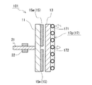
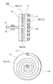
図1〜図3を参照して、実施形態1に係る誘導加熱装置101について説明する。誘導加熱装置101は、回転体11と、加熱部13と、磁束発生部15と、流通路17とを備える。誘導加熱装置101は、磁束発生部15と加熱部13とが回転体11の軸方向に間隔をあけて対向して配置された、所謂アキシャルギャップ型の構造である。以下、誘導加熱装置101の構成を詳しく説明する。
<Induction heating device>
[Embodiment 1]
With reference to FIGS. 1-3, the
(回転体)
回転体11は、回転軸21を有する板状の部材であり、後述する加熱部13と互いの面が対向するように間隔をあけて配置されている。この例では、回転体11は円板状であり、加熱部13に対向する対向面と反対側の反対面の中心に、回転軸21の一端側が固定されている(図1を参照)。回転軸21は、軸受22により回転可能に支持されている。また、回転体11の加熱部13に対向する対向面には、後述する磁束発生部15(この例では永久磁石15m)が設けられている。回転体11の動力には、例えば回転軸21に風車(図示せず)を接続し、風力を利用することが挙げられる。
(Rotating body)
The rotating
回転体11の形成材料としては、磁性材料、非磁性材料を問わず、機械的強度を有し、磁束発生部15を支持可能な材料であればよく、構造強度と長期耐久性(耐候性及び耐食性)に優れる材料が好ましい。例えば、構造用材料に使用される鉄、鋼、ステンレス鋼、アルミニウム合金、マグネシウム合金などの金属や、GFRP(ガラス繊維強化プラスチック)やCFRP(炭素繊維強化プラスチック)などの複合材料が挙げられる。
The material for forming the
(加熱部)
加熱部13は、回転体11に対して軸方向に間隔をあけて対向して配置される板状の部材である。加熱部13は、回転しないようにケーシング(図示せず)に固定されている。加熱部13には、磁束発生部15による磁束が通過し、後述するように渦電流が生じ、誘導加熱によって加熱部13が発熱する。加熱部13は、導電材料からなり、例えば、鉄やアルミニウム、銅などの金属又はそれらの合金で形成されている。
(Heating part)
The
(磁束発生部)
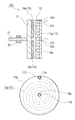
磁束発生部15は、回転体11の加熱部13に対向する対向面に設けられ、加熱部13に対して磁束を発生する。つまり、磁束発生部15は、回転体11の軸方向(加熱部13の方向)に磁束を発生する。この例では、磁束発生部15が永久磁石15mであり、図2に示すように、回転体11の対向面に複数の扇形状の磁石15m(計6個)が円形状に並べて配置され、隣り合う磁石15mの極性が互いに異なっている。また、各磁束発生部15(磁石15m)と加熱部13との間の間隔が径方向に実質的に一定である(図1を参照)。
(Magnetic flux generator)
The magnetic
磁束発生部15としては、永久磁石の他、コイル(電磁石)を用いることも可能である。コイルとしては、銅線などの常電導コイルや超電導線材を用いた超電導コイルが挙げられる。コイルの場合、コイルに通電する電流を大きくすることで、強い磁場を発生させることができ、通電電流を制御することで磁場の強さを調整することも可能である。誘導加熱(渦電流)による発熱量は磁場強度の2乗に比例することから、コイルは永久磁石に比較して発熱量の向上を図り易い。また、コイルであれば、永久磁石に比べて、温度上昇による磁気特性の低下や、経時的な磁気特性の劣化が起こり難い利点がある。したがって、磁束発生部15にコイルを用いた場合、通電電流を大きくして十分な磁場強度を維持し易く、熱媒体を発電に適した所定の温度(例えば、100℃〜600℃、好ましくは200℃〜350℃)まで加熱するのに十分な性能(熱エネルギー)を得易い。
As the
コイルには直流電流を流し、直流磁場を発生させることが挙げられる。例えば、誘導加熱装置101において、磁石15mに代えてコイルを用いる場合、各コイルにスリップリングなどを介して直流電源を接続し、電流を供給する。そして、各コイルに通電する電流の向きを制御して、隣り合うコイルの極性が互いに異なるように、各コイルに発生させる磁場(磁束)の方向を制御することが挙げられる。さらに、コイルに直流電流を流し、直流磁場を発生させる場合、超電導コイルであれば、電気抵抗がゼロであり、大電流を流してもコイルに発熱(損失)が実質的に生じない。そのため、常電導コイルに比較して、大電流を流すことによるコイルの発熱(損失)を抑制することができ、電力損失なしで極めて強い磁場を維持することができる。超電導コイルの場合、例えば、周囲を冷却用ジャケットで覆い、冷却することによって超電導状態に保持することが挙げられる。
For example, a direct current is passed through the coil to generate a direct magnetic field. For example, in the
(流通路)
加熱部13には、熱媒体が流通する流通路17が設けられている。流通路17は、加熱部13の径方向に設けられ、加熱部13の径方向の外側に熱媒体を供給する入口部171と、その径方向の内側に熱媒体を排出する出口部172とを有する。そして、加熱部13の径方向の外側から内側へ熱媒体が流通する(図1中の白抜き矢印は熱媒体の供給・排出方向を示す)。
(Flow passage)
The
この例では、流通路17は、図3に示すように、加熱部13の径方向に渦巻状に設けられている。流通路17は、配管17pによって構成されており、加熱部13の回転体11に対向する対向面とは反対側の反対面に、配管17pを渦巻状に巻き付けて配置している。加熱部13と流通路17(配管17p)とは熱的に接続されている。また、流通路17(配管17p)は、隣り合う流通路17(配管17p)間の間隔が等しくなるように形成されている。具体的には、流通路17(配管17p)は、加熱部13の径方向(熱媒体の流通方向)に略等しいピッチで渦巻状に設けられており、入口部171側から出口部172側に亘って渦巻のピッチが実質的に一定である。したがって、流通路17の入口部171側から出口部172側に亘って加熱部13との接触面積が略等しくなっており、加熱部13において、径方向(熱媒体の流通方向)における単位長さあたりの流通路17との接触面積が入口部171側から出口部172側に亘って略等しい。配管17pは、例えば、鉄やアルミニウム、銅などの金属又はそれらの合金で形成されている。熱媒体としては、例えば、水、水蒸気、油、液体金属(Na、Pbなど)、溶融塩などの液体並びに気体が挙げられる。
In this example, as shown in FIG. 3, the
次に、誘導加熱装置101における熱媒体が加熱されるメカニズムについて説明する。
Next, the mechanism by which the heat medium in the
誘導加熱装置101では、磁束発生部15(磁石15m)から回転体11の軸方向に磁束が発生し、加熱部13に磁束が通過する。具体的には、加熱部13におけるN極の磁束発生部15に対向する部分では、磁束(磁場)が加熱部13の対向面側から反対面側の方向に通過し、S極の磁束発生部15に対向する部分では、磁束(磁場)が加熱部13の反対面側から対向面側の方向に通過する。そして、回転体11と共に磁束発生部15が回転することにより、加熱部13に対して磁束発生部15が相対的に移動することで、加熱部13における磁束発生部15に対向する部分において通過する磁束が変化し、印加される磁場が周期的に変化する。その結果、加熱部13に渦電流が発生することで、加熱部13が発熱し、その熱が流通路17(配管17p)に流れる熱媒体に伝熱され、熱媒体が加熱される。この例では、回転体11の径方向の外側では内側よりも周速が速くなるため、加熱部13を通過する磁束の変化速度(周波数)は外側の方が大きくなる。そのため、加熱部13の径方向の外側、即ち流通路17の入口部171側の方が発熱量が大きい。
In the
また、誘導加熱装置101では、隣り合う磁束発生部15(磁石15m)の極性が互いに異なることから、磁束(磁場)の方向が周期的に逆転しながら変化する。そのため、加熱部13に印加される磁場の振幅(変化)が大きくなるため、より大きな渦電流を発生させることができ、発熱量を増やすことができる。
Moreover, in the
磁束発生部15(磁石15m)の数は、適宜設定することができる。磁束発生部15の数をある程度増やすことで、磁場の周期を短くすることができ、磁場の変化速度が大きくなる。誘導加熱による発熱量は磁場の変化速度に比例することから、磁場の周期を短くすることで、発熱量の向上が期待できる。磁束発生部15の数は、例えば4個以上が好ましく、6個以上、更に8個以上がより好ましい。
The number of magnetic flux generation parts 15 (
{作用効果}
実施形態1の誘導加熱装置101は、加熱部13の径方向の外側に流通路17の入口部171が設けられており、加熱部13の径方向の外側から内側へ熱媒体が流通するように流通路17が構成されている。したがって、発熱量が大きい加熱部13の径方向の外側に流通路17の入口部171が設けられていることから、加熱部13の外側において熱媒体との温度差を大きくでき、発熱量が大きい加熱部13の外側の熱を熱媒体へ十分に伝熱させることができる。よって、加熱部13で発生した熱を、流通路17を流通する熱媒体に効率よく伝熱することができ、加熱部13からの熱ロスが小さく、加熱効率(熱交換効率)を改善できる。加えて、装置の大型化やコストアップを招くことなく、加熱部13で発生した熱を熱媒体によって十分に抜熱でき、過熱による加熱部13の損傷を抑制できる。
{Function and effect}
In the
また、板状の加熱部13に対して流通路17を渦巻状に設けたことで、1つの流通路17で加熱部13全体からの発熱を熱媒体に伝熱できる。
Further, by providing the
[変形例]
実施形態1の誘導加熱装置101では、流通路17を配管17pによって構成し、加熱部13の外部に流通路17を設ける形態を説明したが、流通路17は加熱部13に形成することも可能である。例えば、図4に示すように、加熱部13の反対面に径方向に渦巻状の溝17gを形成し、この溝17gを流通路17に利用することが挙げられる。そして、溝17gを形成した加熱部13の反対面を覆うように、流通路17の入口部171及び出口部172に対応する位置にそれぞれ開口13oが形成された板状のカバー材13cを被せることで、溝17gの内周面とカバー材13cの表面とにより囲まれた空間によって流通路17を形成できる。なお、図4の上図は、流通路17を加熱部13に形成した溝17gによって構成した場合の誘導加熱装置の概略縦断面図であり、下図は、加熱部13に形成した流通路17(溝17g)の概略平面図である。
[Modification]
In the
(断熱材)
実施形態1の誘導加熱装置101において、加熱部13や配管17pの周囲に断熱材(図示せず)を配置してもよい。例えば、加熱部13の対向面及び周面や、配管17pの外側に断熱材を設けることが挙げられる。断熱材には、例えば、ロックウール、グラスウール、発砲プラスチック、レンガ、セラミックスなどを用いることができる。加熱部13や配管17pの周囲に断熱材を設けることで、加熱部13や配管17pからの熱ロスを抑制でき、熱媒体への熱交換効率を向上できる。また、回転体11(磁束発生部15)に対向する加熱部13の対向面に断熱材を配置することで、回転体11(磁束発生部15)に対する加熱部13からの熱の影響を低減できる。回転体11(磁束発生部15)の加熱部13に対向する対向面に断熱材を配置してもよく、これによっても加熱部13からの熱の影響を低減できる。
(Insulation material)
In the
[実施形態2]
上述した実施形態1では、図1に示すように、磁束発生部15と加熱部13との間の間隔が径方向に一定である形態を説明した。実施形態2では、磁束発生部15と加熱部13との間の間隔が流通路17の入口部171側よりも出口部172側の方が大きい形態を説明する。以下、図5を参照して、実施形態2に係る誘導加熱装置102について、実施形態1との相違点を中心に説明する。
[Embodiment 2]
Embodiment 1 mentioned above demonstrated the form that the space | interval between the magnetic
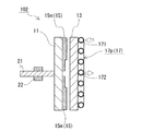
図5に例示する実施形態2の誘導加熱装置102では、各磁束発生部15を構成する各磁石15mの径方向の内側が外側よりも一段凹んでおり、各磁束発生部15と加熱部13との間の間隔が流通路17の入口部171側よりも出口部172側の方が大きくなっている。
In the
{作用効果}
実施形態2の誘導加熱装置102では、流通路17の入口部171側よりも出口部172側の方が磁束発生部15と加熱部13との間の間隔が大きくなるように構成されている。これにより、磁束発生部15と加熱部13との間の間隔が大きい流通路17の出口部172側において、加熱部13の発熱量を抑えることができる。そのため、磁束発生部15と加熱部13との間の間隔が径方向に一様な場合に比べて、流通路17の出口部172側で加熱部13と熱媒体との温度差を大きくできる。したがって、加熱部13から熱媒体への熱の移動量が小さくなる流通路17の出口部172側において、加熱部13で発生した熱を熱媒体へ十分に伝熱させることができる。よって、加熱部13で発生した熱を熱媒体に更に効率よく伝熱することができ、出口部172側の加熱部13からの熱ロスが小さく、熱交換効率をより向上できる。また、装置の大型化やコストアップを招くことなく、出口部172側の加熱部13で発生した熱を熱媒体によって十分に抜熱でき、過熱による加熱部13の損傷をより抑制できる。
{Function and effect}
The
[変形例]
実施形態2の誘導加熱装置102では、回転体11に設けられた各磁束発生部15(磁石15m)に径方向に段差を設けることで、流通路17の出口部172側で磁束発生部15と加熱部13との間の間隔を大きくする形態を説明した。磁束発生部15と加熱部13との間の間隔を大きくするその他の手段としては、例えば、回転体11に対向する加熱部13の対向面に段差を設けることが挙げられる。具体的には、各磁石15mの厚さを径方向に実質的に一定にすると共に、回転体11(磁束発生部15)と加熱部13との対向距離が入口部171側よりも出口部172側が大きくなるように、加熱部13の対向面に径方向に段差を設ける。これにより、出口部172側において、磁束発生部15と加熱部13との間の間隔を大きくすることができる。段差ではなく傾斜を設けてもよく、磁束発生部15と加熱部13との間の間隔は、流通路17の入口部171側から出口部172側に向かって段差を設けて段階的に大きくする他、傾斜を設けて連続的に大きくすることも可能である。
[Modification]
In the
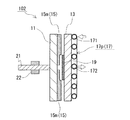
特に、実施形態2の誘導加熱装置102では、流通路17の出口部172側において磁束発生部15と加熱部13との間の間隔が大きくなっているため、その間隔が大きい部分に断熱材を配置したり、配置する断熱材の厚さを厚くすることが容易である。例えば、図6に示すように、加熱部13の対向面のうち、磁束発生部15との間の間隔が大きい部分、即ち流通路17の出口部172側に断熱材19を配置することが挙げられる。流通路17の出口部172側では、熱媒体の温度が高く、加熱部13の温度も高くなる傾向があるため、熱ロスが生じ易いが、流通路17の出口部172側に断熱材19を配置したり、断熱材19を厚くすることによって、熱ロスを効果的に抑制できる。
In particular, in the
[実施形態3]
上述した実施形態1では、図1及び図3に示すように、流通路17の渦巻のピッチが一定であり、流通路17が入口部171側から出口部172側に亘って加熱部13との接触面積が等しくなるように形成されている形態を説明した。実施形態3では、流通路17が加熱部13の径方向に渦巻状に設けられると共に、入口部171側よりも出口部172側の方が加熱部13との接触面積が大きくなるように形成されている形態を説明する。以下、図7を参照して、実施形態3に係る誘導加熱装置103について、実施形態1との相違点を中心に説明する。なお、図7の上図は、図1と同様に、誘導加熱装置の概略縦断面図であり、下図は、図3と同様に、流通路の概略平面図である。
[Embodiment 3]
In the first embodiment described above, as shown in FIGS. 1 and 3, the spiral pitch of the
図7に例示する実施形態3の誘導加熱装置103では、流通路17(配管17p)は、入口部171側よりも出口部172側の方が隣り合う流通路17(配管17p)間の間隔が小さくなるように形成されている。具体的には、流通路17の入口部171側から出口部172側に向かうほど、流通路17の渦巻のピッチが小さくなっており、加熱部13に対して流通路17が密に設けられている。したがって、流通路17の入口部171側よりも出口部172側の方が加熱部13との接触面積が大きくなっており、加熱部13において、径方向(熱媒体の流通方向)における単位長さあたりの流通路17との接触面積が入口部171側よりも出口部172側の方が大きい。
In the
{作用効果}
実施形態3の誘導加熱装置103では、流通路17の入口部171側よりも出口部172側の方が加熱部13との接触面積が大きくなるように流通路17が構成されている。これにより、流通路17の出口部172側において、加熱部13から流通路17に流れる熱媒体への熱の移動量を増やすことができる。したがって、加熱部13から熱媒体への熱の移動量が小さくなる流通路17の出口部172側において、加熱部13で発生した熱を熱媒体へ十分に伝熱させることができる。よって、加熱部13で発生した熱を熱媒体に更に効率よく伝熱することができ、出口部172側の加熱部13からの熱ロスが小さく、熱交換効率をより向上できる。また、装置の大型化やコストアップを招くことなく、出口部172側の加熱部13で発生した熱を熱媒体によって十分に抜熱でき、過熱による加熱部13の損傷をより抑制できる。
{Function and effect}
In the
[変形例]
実施形態3の誘導加熱装置103では、加熱部13に対して渦巻状の流通路17を1つ設ける形態を説明したが、複数の流通路を設けることも可能である。例えば、図8に示すように、加熱部13の径方向に放射状に複数の流通路17を設けることが挙げられる。各流通路17は、加熱部13の径方向の外側から内側に向かって直線状に設けられ、加熱部13の径方向の外側に入口部171が、その径方向の内側に出口部172が設けられている。この例では、各流通路17は、配管17pによって構成されており、各配管17pを加熱部13の反対面に配置している。この場合であっても、流通路17(配管17p)の入口部171側よりも出口部172側の方が隣り合う流通路17(配管17p)間の間隔が小さくなるため、流通路17の入口部171側よりも出口部172側の方が加熱部13との接触面積が大きくなる。図8では、流通路17(配管17p)の数が8個の場合を例示しているが、流通路17(配管17p)の数はこれに限定されず、適宜設定することができる。流通路17の数は、加熱部13との接触面積を確保する観点から、例えば4個以上、8個以上、更に12個以上とすることが挙げられる。また、図8では、加熱部13を平面視した場合に、流通路17(配管17p)が加熱部13の径方向に直線状に設けられているが、流通路17(配管17p)は波線状に設けることも可能である。
[Modification]
In the
[実施形態4]
上述した実施形態1において、実施形態2及び実施形態3で説明した構成を組み合わせることも可能である。図9に例示する実施形態4に係る誘導加熱装置104のように、流通路17の入口部171側よりも出口部172側の方が磁束発生部15と加熱部13との間の間隔が大きくなると共に、流通路17の入口部171側よりも出口部172側の方が加熱部13との接触面積が大きくなるように構成することが挙げられる。これにより、加熱部13から熱媒体への熱の移動量が小さくなる流通路17の出口部172側において、加熱部13で発生した熱を熱媒体へより十分に伝熱させることができ、出口部172側の加熱部13で発生した熱を熱媒体によってより十分に抜熱できる。
[Embodiment 4]
In the above-described first embodiment, the configurations described in the second and third embodiments can be combined. Like the
〈発電システム〉
図10を参照して、本発明の実施形態に係る発電システムの一例を説明する。図10に示す発電システムPは、誘導加熱装置10と、風車20と、蓄熱器50と、発電部60とを備える。塔91の上部に設置されたナセル92に風車20が取り付けられ、ナセル92内に誘導加熱装置10が格納されている。また、塔91の下部(土台)に建てられた建屋93に蓄熱器50及び発電部60が設置されている。以下、発電システムPの構成を詳しく説明する。
<Power generation system>
An example of the power generation system according to the embodiment of the present invention will be described with reference to FIG. A power generation system P shown in FIG. 10 includes an
誘導加熱装置10は、本発明の実施形態に係る誘導加熱装置であり、例えば、上述した実施形態1〜4に係る誘導加熱装置101〜104を利用することができる。また、回転軸21の他端側が後述する風車20に直結され、回転体を回転させる動力に風力を利用している。なお、ここでは、熱媒体が水である場合を例に説明する。
The
風車20は、水平方向に延びる回転軸21を中心に、3枚の翼201を回転軸21に放射状に取り付けた構造である。出力が5MWを超える風力発電システムの場合、直径が120m以上、回転数が10〜20rpm程度である。
The windmill 20 has a structure in which three
誘導加熱装置10の流通路(配管)には、誘導加熱装置10に水を供給する給水管73と、誘導加熱装置10により加熱した水を蓄熱器50に送る輸送管51とが接続されている。そして、誘導加熱装置10は、回転体に設けられた磁場発生部から磁束が発生し、回転体の回転により、回転体と間隔をあけて配置された加熱部を通過する磁束が変化することで、加熱部に渦電流が発生し、加熱部が発熱して流通路内の水を加熱する。誘導加熱装置10は、熱媒体である水を例えば100℃〜600℃といった高温に加熱する。また、誘導加熱装置10は、加熱部(流通路)が回転しない構造であるので、流通路と輸送管51及び給水管73との接続に回転継手を用いる必要がなく、例えば溶接などを用いて、簡易な構成で、堅牢な接続を実現できる。
A
この発電システムPは、誘導加熱装置10により水を発電に適した温度(例えば200℃〜350℃)まで加熱し、高温高圧水を発生させる。高温高圧水は、誘導加熱装置10と蓄熱器50とを連結する輸送管51を通って蓄熱器50に送られる。蓄熱器50は、輸送管51を通って送られてきた高温高圧水の熱を蓄え、また、熱交換器を用いて発電に必要な蒸気を発電部60に供給する。なお、誘導加熱装置10により蒸気を発生させてもよい。
In the power generation system P, water is heated to a temperature suitable for power generation (for example, 200 ° C. to 350 ° C.) by the
蓄熱器50としては、例えば、蒸気アキュムレーターや、溶融塩や油などを用いた顕熱型、或いは、融点の高い溶融塩の相変化を利用した潜熱型の蓄熱器を利用することができる。潜熱型の蓄熱方式は蓄熱材の相変化温度で蓄熱を行うため、一般に、顕熱型の蓄熱方式に比べて蓄熱温度域が狭帯域であり、蓄熱密度が高い。
As the
発電部60は、蒸気タービン61と発電機62とを組み合わせた構造であり、蓄熱器50から供給された蒸気によって蒸気タービン61が回転し、発電機62を駆動して発電する。
The
蓄熱器50に送られた高温高圧水又は蒸気は、復水器71で冷却され水に戻される。その後、ポンプ72に送られ、高圧水にして給水管73を通って誘導加熱装置10に送られることで循環する。
The high-temperature high-pressure water or steam sent to the
この発電システムPによれば、本発明の実施形態に係る誘導加熱装置10を備えることから、誘導加熱装置10において、加熱部で発生した熱を、流通路を流通する熱媒体に効率よく伝熱することができる。よって、誘導加熱装置10における熱媒体の熱交換効率を改善でき、発電効率の向上を図ることができる。その他、誘導加熱装置10により加熱した熱媒体の熱を蓄熱器50に蓄熱して発電することで、高価な蓄電池を用いなくても、需要に応じた安定的な発電を実現できる。また、風車20と誘導加熱装置10の回転軸21とを直結することにより、増速機(ギアボックス)のトラブルを回避することが可能である。さらに、熱媒体の熱を輸送管51により例えば塔91の下部(土台)に設置された発電部60に供給することで、ナセル92に発電部60を格納する必要がなく、塔91の上部に設置されるナセル92を小型・軽量化することができる。
According to this power generation system P, since the
上記した発電システムPでは、熱媒体に水を用いた場合を例に説明したが、水よりも熱伝導率の高い液体金属を熱媒体に用いてもよい。このような液体金属としては、例えば液体金属ナトリウムが挙げられる。液体金属を熱媒体に用いる場合は、例えば、加熱部から熱を受け取る一次熱媒体に液体金属を用い、輸送管を通って送られてきた液体金属の熱で熱交換器を介して二次熱媒体(水)を加熱し、蒸気を発生させることが考えられる。 In the power generation system P described above, the case where water is used as the heat medium has been described as an example, but a liquid metal having a higher thermal conductivity than water may be used as the heat medium. An example of such a liquid metal is liquid metal sodium. When using a liquid metal as the heat medium, for example, the liquid metal is used as the primary heat medium that receives heat from the heating unit, and the secondary heat is transmitted through the heat exchanger using the heat of the liquid metal sent through the transport pipe. It is conceivable that the medium (water) is heated to generate steam.
また、常圧で100℃超の沸点を有する例えば油、液体金属、溶融塩などを熱媒体に用いた場合は、水に比較して、所定の温度まで加熱したときに、流通路内の熱媒体の気化による内圧上昇を抑制し易い。 In addition, when oil, liquid metal, molten salt, or the like having a boiling point of over 100 ° C. at normal pressure is used as the heat medium, the heat in the flow path is increased when heated to a predetermined temperature compared to water. It is easy to suppress an increase in internal pressure due to vaporization of the medium.
本発明の誘導加熱装置は、再生可能エネルギー(例、風力)を利用した発電システムに利用する他、例えば給湯システムや暖房システムに利用することも可能である。また、本発明の発電システムは、再生可能エネルギーを利用した発電の分野に好適に利用可能である。 The induction heating device of the present invention can be used for, for example, a hot water supply system and a heating system, in addition to being used for a power generation system using renewable energy (eg, wind power). Moreover, the power generation system of the present invention can be suitably used in the field of power generation using renewable energy.
10、101〜104 誘導加熱装置 P 発電システム
11 回転体
13 加熱部
13c カバー材 13o 開口
15 磁束発生部
15m 永久磁石
17 流通路
17p 配管 17g 溝
171 入口部 172 出口部
19 断熱材
21 回転軸 22 軸受
20 風車 201 翼
50 蓄熱器 51 輸送管
60 発電部 61 蒸気タービン 62 発電機
71 復水器 72 ポンプ 73 給水管
91 塔 92 ナセル 93 建屋
DESCRIPTION OF
Claims (6)
回転軸を有する板状の回転体と、
前記回転体に対して軸方向に間隔をあけて対向して配置される板状の加熱部と、
前記回転体の前記加熱部に対向する対向面に設けられ、前記加熱部に対して磁束を発生する磁束発生部と、
前記加熱部の径方向に設けられ、前記熱媒体が流通する流通路と、を備え、
前記流通路は、前記加熱部の径方向の外側に前記熱媒体を供給する入口部と、その径方向の内側に前記熱媒体を排出する出口部と、を有する誘導加熱装置。 An induction heating device for heating a heat medium,
A plate-like rotating body having a rotating shaft;
A plate-like heating unit disposed to face the rotating body with an interval in the axial direction;
A magnetic flux generator provided on an opposing surface of the rotating body that faces the heating unit, and generates a magnetic flux with respect to the heating unit;
A flow path provided in a radial direction of the heating unit and through which the heat medium flows,
The said flow path is an induction heating apparatus which has an inlet part which supplies the said heat medium to the outer side of the radial direction of the said heating part, and an outlet part which discharges | emits the said heat medium inside the radial direction.
前記誘導加熱装置により加熱した前記熱媒体の熱を電気エネルギーに変換する発電部と、を備える発電システム。 The induction heating device according to any one of claims 1 to 5,
A power generation system comprising: a power generation unit that converts heat of the heat medium heated by the induction heating device into electrical energy.
Priority Applications (1)
| Application Number | Priority Date | Filing Date | Title |
|---|---|---|---|
| JP2015123352A JP2017010696A (en) | 2015-06-18 | 2015-06-18 | Induction heating apparatus and power generation system |
Applications Claiming Priority (1)
| Application Number | Priority Date | Filing Date | Title |
|---|---|---|---|
| JP2015123352A JP2017010696A (en) | 2015-06-18 | 2015-06-18 | Induction heating apparatus and power generation system |
Publications (1)
| Publication Number | Publication Date |
|---|---|
| JP2017010696A true JP2017010696A (en) | 2017-01-12 |
Family
ID=57763888
Family Applications (1)
| Application Number | Title | Priority Date | Filing Date |
|---|---|---|---|
| JP2015123352A Pending JP2017010696A (en) | 2015-06-18 | 2015-06-18 | Induction heating apparatus and power generation system |
Country Status (1)
| Country | Link |
|---|---|
| JP (1) | JP2017010696A (en) |
Cited By (3)
| Publication number | Priority date | Publication date | Assignee | Title |
|---|---|---|---|---|
| CN112701704A (en) * | 2020-12-29 | 2021-04-23 | 鸿鲲新能源(海南)有限公司 | Series disk type excitation magnetic heating system and heating method thereof |
| CN112713602A (en) * | 2020-12-29 | 2021-04-27 | 鸿鲲新能源(海南)有限公司 | Disk type excitation magnetic heating system and heating method thereof |
| KR20230105226A (en) * | 2022-01-03 | 2023-07-11 | 김종필 | System for wind generator |
-
2015
- 2015-06-18 JP JP2015123352A patent/JP2017010696A/en active Pending
Cited By (4)
| Publication number | Priority date | Publication date | Assignee | Title |
|---|---|---|---|---|
| CN112701704A (en) * | 2020-12-29 | 2021-04-23 | 鸿鲲新能源(海南)有限公司 | Series disk type excitation magnetic heating system and heating method thereof |
| CN112713602A (en) * | 2020-12-29 | 2021-04-27 | 鸿鲲新能源(海南)有限公司 | Disk type excitation magnetic heating system and heating method thereof |
| KR20230105226A (en) * | 2022-01-03 | 2023-07-11 | 김종필 | System for wind generator |
| KR102761945B1 (en) * | 2022-01-03 | 2025-02-03 | 김종필 | System for wind generator |
Similar Documents
| Publication | Publication Date | Title |
|---|---|---|
| JP6465457B2 (en) | Induction heating apparatus and power generation system | |
| JP5739737B2 (en) | Induction heating apparatus and power generation system including the same | |
| JP6560588B2 (en) | Induction heating apparatus and power generation system | |
| JP5413814B2 (en) | Power generation system | |
| TW201132244A (en) | Power generating system | |
| JP5344380B2 (en) | Power generation system | |
| JP5545436B2 (en) | Power generation system | |
| JP2017010696A (en) | Induction heating apparatus and power generation system | |
| JP5637452B2 (en) | Induction heating apparatus and power generation system including the same | |
| JP2017010698A (en) | Induction heating apparatus and power generation system | |
| JP2011129433A (en) | Induction heating device and power generation system equipped with the same | |
| JP5293626B2 (en) | Induction heating apparatus and power generation system including the same | |
| JP5435357B2 (en) | Power generation system | |
| WO2011093192A1 (en) | Power generation system | |
| JP7258286B2 (en) | Heat generator and energy storage system | |
| JP5778969B2 (en) | Power generation system | |
| JP2011216421A (en) | Induction heating device and power generation system including the same | |
| JP2011220181A (en) | Heat medium heating device and power generation system equipped with the same |