JP2017010731A - connector - Google Patents
connector Download PDFInfo
- Publication number
- JP2017010731A JP2017010731A JP2015124192A JP2015124192A JP2017010731A JP 2017010731 A JP2017010731 A JP 2017010731A JP 2015124192 A JP2015124192 A JP 2015124192A JP 2015124192 A JP2015124192 A JP 2015124192A JP 2017010731 A JP2017010731 A JP 2017010731A
- Authority
- JP
- Japan
- Prior art keywords
- female
- male
- terminals
- connector
- terminal
- Prior art date
- Legal status (The legal status is an assumption and is not a legal conclusion. Google has not performed a legal analysis and makes no representation as to the accuracy of the status listed.)
- Granted
Links
Images


Landscapes
- Details Of Connecting Devices For Male And Female Coupling (AREA)
Abstract
【課題】メス端子及びオス端子の振動を抑えることのできるコネクタを提案する。【解決手段】オスハウジング25内にオス端子29,30が設けられたオス型コネクタ12と、メスハウジング16内にメス端子17,18が設けられたメス型コネクタ11とを備え、オス端子29,30間に触手防止用リブ31を、メス端子17,18間にスリット21を有するフロントホルダ19をそれぞれ設け、オス型コネクタとメス型コネクタとの接続時に、触手防止用リブ31をスリット21内に押し込むことで、フロントホルダ19は、押し込み方向の力をオス端子29,30がそれぞれ嵌合されたメス端子17,18側に方向変換し、メス端子17,18をメスハウジング16に押し付ける。【選択図】図3A connector capable of suppressing vibration of a female terminal and a male terminal is proposed. A male connector 12 in which male terminals 29 and 30 are provided in a male housing 25 and a female connector 11 in which female terminals 17 and 18 are provided in a female housing 16 are provided. A front holder 19 having a tentacle prevention rib 31 between 30 and a slit 21 between the female terminals 17 and 18 is provided, and the tentacle prevention rib 31 is inserted into the slit 21 when the male connector and the female connector are connected. By pushing in, the front holder 19 changes the force in the pushing direction toward the female terminals 17 and 18 into which the male terminals 29 and 30 are fitted, and presses the female terminals 17 and 18 against the female housing 16. [Selection] Figure 3
Description
本発明は、メス型コネクタとオス型コネクタとが互いに接続されるコネクタに関する。 The present invention relates to a connector in which a female connector and a male connector are connected to each other.
例えば、メス型コネクタにはメスハウジングの内部に一対のメス端子が、オス型コネクタにはオスハウジングの内部に一対のオス端子がそれぞれ設けられている。このうち、メス端子はランスによってメスハウジングに係止され、メスハウジング内に固定されている。すなわち、メス端子をメスハウジングに組付ける際、メス端子をメスハウジング内に挿入すると、可倒式のランスがメス端子によって撓み、メス端子の挿入完了後に、ランスが自身の復元力で戻ってメス端子を保持することで、メス端子はメスハウジング内に固定される(例えば、特許文献1参照)。 For example, the female connector is provided with a pair of female terminals inside the female housing, and the male connector is provided with a pair of male terminals inside the male housing. Among these, the female terminal is locked to the female housing by a lance and is fixed in the female housing. In other words, when the female terminal is assembled to the female housing, if the female terminal is inserted into the female housing, the retractable lance is deflected by the female terminal, and after the female terminal has been inserted, the lance returns with its own restoring force. By holding the terminal, the female terminal is fixed in the female housing (see, for example, Patent Document 1).
また、上記特許文献1においては、メス端子をメスハウジング内に挿入する際に人の手で作業できるよう、またランスの撓み量を十分に確保するように、メス端子とメスハウジングとの間には隙間が設けられている。 In Patent Document 1, the female terminal is inserted between the female terminal and the female housing so that the female terminal can be manually operated when inserted into the female housing, and the lance is sufficiently bent. Is provided with a gap.
しかしながら、上記従来技術のように、メス端子とメスハウジングとの間に隙間が設けられていると、車両の振動をワイヤーハーネスが受けた場合に、その振動がメス端子に伝わり、メス端子が相手側のオス端子と共に振動し、メス端子とオス端子との接点部で摩耗が発生するという問題がある。このような摩耗は、振動が大きいほど摩耗量が増大し且つ広範囲に及ぶ。 However, if a clearance is provided between the female terminal and the female housing as in the prior art, when the wire harness receives the vibration of the vehicle, the vibration is transmitted to the female terminal, and the female terminal It vibrates with the male terminal on the side, and there is a problem that wear occurs at the contact portion between the female terminal and the male terminal. Such wear increases as the vibration increases, and the wear amount increases over a wide range.
なお、ハウジングが車両内の所定位置にボルトで締結されるタイプは振動に強いが、ワイヤーハーネスの車両組付け作業性が悪く、作業スペースも確保しなければならない。 Note that the type in which the housing is fastened with a bolt to a predetermined position in the vehicle is strong against vibration, but the vehicle assembly workability of the wire harness is poor, and a work space must be secured.
本発明の課題は、メス端子及びオス端子の振動を抑えることのできるコネクタを提案することにある。 The subject of this invention is proposing the connector which can suppress the vibration of a female terminal and a male terminal.
上記課題を達成するため、請求項1に記載の発明は、オスハウジング内に一対のオス端子が設けられたオス型コネクタと、メスハウジング内に一対のメス端子が設けられたメス型コネクタとを備え、オス端子間にオス側中間体を、メス端子間にメス側中間体をそれぞれ設け、オス型コネクタとメス型コネクタとの接続時に、オス側中間体をメス側中間体に押し込むことで、オス側中間体及びメス側中間体は、押し込み方向の力をオス端子が嵌合されたメス端子側に方向変換し、該メス端子をオスハウジング又はメスハウジングに押し付けることを特徴とする。 In order to achieve the above object, the invention described in claim 1 includes a male connector in which a pair of male terminals are provided in a male housing, and a female connector in which a pair of female terminals are provided in a female housing. Equipped with a male intermediate between the male terminals, a female intermediate between the female terminals, and by pushing the male intermediate into the female intermediate when connecting the male connector and female connector, The male side intermediate body and the female side intermediate body are characterized in that the force in the push-in direction is changed to the female terminal side to which the male terminal is fitted, and the female terminal is pressed against the male housing or the female housing.
これによれば、オス側中間体及びメス側中間体が、オス側中間体をメス側中間体に押し込む方向の力をメス端子側に方向変換するので、メス端子をオスハウジング又はメスハウジングに押し付けることができる。これにより、メス端子と接続されたオス端子もメス端子に押さえ付けられるから、オス端子とメス端子の振動を抑制することができ、その結果、端子間の接点部の摩耗を防ぐことができる。 According to this, since the male side intermediate body and the female side intermediate body change the direction of pushing the male side intermediate body into the female side intermediate body to the female terminal side, the female terminal is pressed against the male housing or the female housing. be able to. Thereby, since the male terminal connected to the female terminal is also pressed against the female terminal, vibration of the male terminal and the female terminal can be suppressed, and as a result, wear of the contact portion between the terminals can be prevented.
この場合において、オス側中間体及びメス側中間体のうち一方は平板で、他方は平板が嵌合するスリットを有するブロックでそれぞれ構成され、ブロックは、弾性を有する材料で形成され、スリットの少なくとも奥部の幅が平板の板厚よりも狭く形成されていることが好ましい。 In this case, one of the male side intermediate body and the female side intermediate body is a flat plate, and the other is constituted by a block having a slit into which the flat plate is fitted, and the block is formed of an elastic material, and at least the slit is formed. It is preferable that the width of the inner portion is narrower than the thickness of the flat plate.
これによれば、平板がスリットに嵌合することで、スリットが容易に押し広げられるから、オス側中間体をメス側中間体に押し込む方向の力をオス端子側及びメス端子側に効率よく方向変換することができる。 According to this, since the flat plate fits into the slit, the slit is easily pushed and spread, so the force in the direction of pushing the male intermediate body into the female intermediate body is efficiently directed to the male terminal side and the female terminal side. Can be converted.
また、平板は、断面が楔形に形成されていることが好ましい。 The flat plate is preferably formed in a wedge shape in cross section.
これによれば、スリット幅を確実に押し広げることができる。 According to this, the slit width can be surely widened.
また、ブロックがメスハウジングに収容されており、ブロックの側面には突起が、メス端子の側面には突起が係合する段部がそれぞれ形成されていることが好ましい。 Preferably, the block is accommodated in the female housing, and a projection is formed on the side surface of the block, and a step portion is formed on the side surface of the female terminal.
これによれば、ブロック側面の突起がメス端子側面の段部に係合することで、メス端子の保持力を高めることができる。 According to this, the holding force of the female terminal can be increased by engaging the protrusion on the side surface of the block with the step on the side surface of the female terminal.
本発明によれば、メス端子及びオス端子の振動を抑えることのできるコネクタを得ることができる。 ADVANTAGE OF THE INVENTION According to this invention, the connector which can suppress the vibration of a female terminal and a male terminal can be obtained.
(第1の実施形態)
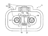
以下、本発明の実施の形態を説明する。図1〜図3は第1の実施形態によるコネクタを示しており、図1はメス型コネクタの正面図、図2はオス型コネクタの斜視図、図3はメス型コネクタとオス型コネクタとを互いに接続したときの断面図である。
(First embodiment)
Embodiments of the present invention will be described below. 1 to 3 show a connector according to the first embodiment, FIG. 1 is a front view of a female connector, FIG. 2 is a perspective view of a male connector, and FIG. 3 shows a female connector and a male connector. It is sectional drawing when mutually connected.
図1〜図3に示すように、本実施形態に係るコネクタ10は、メス型コネクタ11とオス型コネクタ12とを有している。
As shown in FIGS. 1 to 3, the connector 10 according to this embodiment includes a
メス型コネクタ11は、図1に示すように、合成樹脂からなるメスハウジング13を有し、このメスハウジング13には、4つの隅部がアール状に形成された角形筒形状のメスハウジング本体14と、メスハウジング本体14の上部に設けられたメス結合部15とが設けられている。
As shown in FIG. 1, the
メスハウジング本体14の内部には、縦断面が長円形状をなした筒状の内側メスハウジング16が設けられている。なお、この内側メスハウジング16はメスハウジング13の一部をなしている。
Inside the female housing
内側メスハウジング16の内部には、略円筒形状を成し金属製の一対のメス端子17,18が配列されている。内側メスハウジング16のフロント側(図1において、紙面垂直方向手前側)の端部は、メスハウジング本体14の端面と面一になっている(図3参照)。また、メス端子17,18の外周面には、外側に向かって膨出した、段部としての膨出部17a,18aが形成されている(図3)。
Inside the inner
内側メスハウジング16は、フロント側の端部がメス端子17,18側に折り曲げられ、メス端子17,18のフロント側端面の一部を覆っている。すなわち、図1に示すように、メス型コネクタ11を正面から見ると、メス端子17,18は、それらの内周側端面だけが見える。
The inner
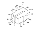
メス端子17,18間には、メス側中間体としてのフロントホルダ19が設けられている。このフロントホルダ19は、図4に示すように、弾性を有する材料(例えば、合成樹脂)で形成され、ブロック状をなし、その両側面19aには突起20が形成されている。突起20は、フロントホルダ19の側面19aに垂直な垂直面20aと、側面19aに対して傾斜した傾斜面20bと、フロントホルダ19の側面19aに垂直な垂直面20cとを有し、横断面が台形をなしている。傾斜面20bは、フロントホルダ19のリア側(図4の右斜め上方)に向かって側面19aに近づく方向に傾斜している。
A
また、フロントホルダ19のフロント面(図3の左斜め下方側の面)19bの中央には、フロントホルダ19の上面19cから底面19dに向かって縦方向にスリット21が形成されている。スリット21は、フロントホルダ19のリア面(図の右斜め上方側の面)19eの近くまで達し、その先端部21aはアール状に形成されている。
Further, a
上述したように、内側メスハウジング16は、フロント側の端部がメス端子17,18側に折り曲げられ、その折り曲げられた部分の中央に開口部が形成されている。そして、フロントホルダ19のメス型コネクタ11への組付時には、フロントホルダ19は、内側メスハウジング16のフロント側から開口部を介してメス端子17,18間に押し込まれる。このとき、フロントホルダ19の両側面19aの突起20が、メス端子17,18の外周面にそれぞれ形成された膨出部17a,18aを押し付ける(このとき、フロントホルダ19はスリット21が閉じる方向に弾性変形した状態となる)。そして、さらに奥まで押し込まれたフロントホルダ19は、各突起20が膨出部17a,18aを乗り越え、内側メスハウジング16の中央部に設けられた芯部材22(図3参照)に突き当たる。各突起20がメス端子17,18の膨出部17a,18aを乗り越えると、フロントホルダ19は、膨出部17a,18aで強固に保持され、メス型コネクタ11から抜け落ちるのが防止される。
As described above, the inner
一方、オス型コネクタ12は、図2に示すように、オスハウジング25を有し、このオスハウジング25には、4つの隅部がアール状に形成された角筒状のオスハウジング本体26と、オスハウジング本体26の上部に設けられたオス結合部27とが設けられている。
On the other hand, as shown in FIG. 2, the
オスハウジング本体26の内部には端子支持板28が設けられ、この端子支持板28に略円柱形状の一対のオス端子29,30が配列されている。オス端子29,30は、図3に示すように、円筒状を成し金属製のオス端子本体29a,30aと、オス端子本体29a,30aの内部に嵌装され合成樹脂から成る芯材29b,30bとを有している。芯材29b,30bは、それぞれオス端子29,30の先端部を形成している。
A
また、オス端子29,30間には、図2に示すように、オス側中間体としての触手防止用リブ31が設けられている。この触手防止用リブ31は、フロントホルダ19に形成されたスリット21に対向配置されている。触手防止用リブ31は、オス端子29,30に手が触れるのを防止すると共にオス端子29,30間でショートが生じるのを防ぐためのもので、合成樹脂で形成されている。触手防止用リブ31は、縦断面がI型を成し、奧側全体が端子支持板28に固定されており、オス端子29側又はオス端子30側に傾かないようになっている。つまり、触手防止用リブ31は、端子支持板28に対して常に垂直となっている。
Further, as shown in FIG. 2, a
上記構成において、オス型コネクタ12とメス型コネクタ11とを互いに接続すると、図3に示すように、オスハウジング本体26がメスハウジング本体14と内側メスハウジング16との間に入り込むとともに、オス端子29,30がメス端子17,18内にそれぞれ嵌合する。また、同時に、オス型コネクタ12の触手防止用リブ31がメス型コネクタ11のフロントホルダ19に形成されたスリット21内に押し込まれる。なお。このとき、メス型コネクタ11のメス結合部15とオス型コネクタ12のオス結合部27とが互いに結合する。
In the above configuration, when the
ここで、スリット21の幅H(図4参照)は、触手防止用リブ31の板厚と同じか、同板厚よりも狭く設定されている。そして、触手防止用リブ31及びフロントホルダ19は、触手防止用リブ31をスリット21に押し込む力を、オス端子29,30側及びメス端子17,18側に方向変換する。すなわち、スリット21の幅Hが触手防止用リブ31の板厚と同じか、それよりも狭くなっているので、触手防止用リブ31がスリット21に押し込まれると、スリット21の幅が広がって、これにより、フロントホルダ19はオス端子29,30側及びメス端子17,18側に広がる。そのため、オス端子29が嵌合されたメス端子17及びオス端子30が嵌合されたメス端子18を、それぞれ、内側メスハウジング16(つまり、メスハウジング13)に押し付けることができる。
Here, the width H of the slit 21 (see FIG. 4) is set to be the same as the plate thickness of the
図3において、符号32,33はそれぞれメス端子17,18に接続されたメス側ケーブル、符号34,35はそれぞれオス端子29,30に接続されたオス側ケーブルである。
3,
ここで、触手防止用リブ31を楔形にすれば、この触手防止用リブ31をスリット21に押し込む力を、オス端子29が嵌合されたメス端子17側及びオス端子30が嵌合されたメス端子18側に効率よく方向変換することができる。なお、触手防止用リブ31はストレート形状で、フロントホルダ19のスリット21を断面(横断面)形状がV字型のものとすることもできる。
Here, if the tentacle-preventing
このように、オス端子29が嵌合されたメス端子17及びオス端子30が嵌合されたメス端子18を、それぞれメスハウジング13に押し付けるようにすれば、メス端子17,18とメスハウジング13との間に隙間が生じることがなく、しかも、メス端子17,18に嵌合されたオス端子29,30はそれぞれメス端子17,18に押し付けられて、端子間の密着性が高められる。したがって、車両から振動を受けても、メス端子17,18及びオス端子29,30の振動を抑制することができるから、結果として、端子間の接点部の摩耗を抑えられ、端子間の通電性の低下を回避することができる。
Thus, if the
本実施形態では、フロントホルダ19がメス端子17,18を係止しているから、ランスとともにメス端子17,18を保持することでメス端子17,18の保持力を高めることができる。そのため、既存のランスを小型化したり、省略することで、コネクタを小型化することができる。
In the present embodiment, since the
本実施形態では、オスハウジング本体26がメスハウジング本体14と内側メスハウジング16との間に入り込む構造となっているため、オス端子29が嵌合されたメス端子17及びオス端子30が嵌合されたメス端子18が、それぞれ、内側メスハウジング16を押し付けているが、例えば、オスハウジング本体26が、内側メスハウジング16の内側に入り込む構造であれば、オス端子29が嵌合されたメス端子17及びオス端子30が嵌合されたメス端子18を、それぞれ、オスハウジング本体26(オスハウジング25)に押し付けるように構成することもできる。また、フロントホルダ19がオスハウジング本体26に収容される構造であれば、オス端子29が嵌合されたメス端子17及びオス端子30が嵌合されたメス端子18を、それぞれ、オスハウジング本体26に押し付けることもできる。
In this embodiment, since the male housing
上記構成においては、メス型コネクタ11にフロントホルダ19を、オス型コネクタ12に触手防止用リブ31をそれぞれ設けたが、これらを逆にして、メス型コネクタ11に触手防止用リブ31を、オス型コネクタ12にフロントホルダ19をそれぞれ設けてもよい。
In the above configuration, the
(第2の実施形態)
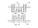
図5は、第2の実施形態を示している。本実施形態では、メス端子17,18の間にメス側中間体としてブロック状のフロントホルダ40が、オス端子29,30の間にオス側中間体として挟持部41がそれぞれ設けられている。挟持部41は全体が弾性を有する材料で形成され、両側にアーム41aを有している。アーム41aの先端における幅W1は、フロントホルダ40の幅W2と同じか、またはフロントホルダ40の幅W2よりも狭くなっている。なお、アーム41aの先端内側はアール状(又は傾斜面)に形成されている。
(Second Embodiment)
FIG. 5 shows a second embodiment. In the present embodiment, a block-shaped
メス型コネクタ11とオス型コネクタ12の接続時に、両アーム41aをフロントホルダ40の両側面40aに沿って押し込むと、両アーム41aは、それぞれ、オス端子29,30が嵌合されたメス端子17,18側へ変位する。すなわち、挟持部41は、両アーム41aをフロントホルダ40に押し込む力を、メス端子17,18側に方向変換することになる。
When the
なお、メス端子17,18の間に挟持部41を、オス端子29,30の間にフロントホルダ40をそれぞれ設けるようにしてもよい。
In addition, you may make it provide the clamping
以上、本発明の各実施形態を図面により詳述してきたが、上記各実施形態は本発明の例示にしか過ぎないものであり、本発明は上記各実施形態の構成に限定されるものではない。本発明の要旨を逸脱しない範囲の設計の変更等があっても、本発明に含まれることは勿論である。 As mentioned above, although each embodiment of this invention has been explained in full detail with drawing, each said embodiment is only the illustration of this invention, and this invention is not limited to the structure of each said embodiment. . Needless to say, changes in design and the like within the scope of the present invention are included in the present invention.
例えば、第1の実施形態では、メス端子が一対でオス端子も一対である2極の場合であったが、メス端子が3個でオス端子も3個ある3極の場合にも本発明は適用できる。この場合、3個のメス端子のうち一対のメス端子の間にメス側中間体を設けるとともに、メス側中間体に対向させて一対のオス端子の間にオス側中間体を設ければよい。 For example, in the first embodiment, the case has two poles with a pair of female terminals and a pair of male terminals. However, the present invention can be applied to a case of three poles with three female terminals and three male terminals. Applicable. In this case, a female side intermediate body may be provided between a pair of female terminals among the three female terminals, and a male side intermediate body may be provided between the pair of male terminals so as to face the female side intermediate body.
10 コネクタ
11 メス型コネクタ
12 オス型コネクタ
13 メスハウジング
17,18 メス端子
17a,18a 膨出部(段部)
19 フロントホルダ(メス側中間体)
20 突起
21 スリット
25 オスハウジング
29,30 オス端子
31 触手防止用リブ(オス側中間体)
DESCRIPTION OF SYMBOLS 10
19 Front holder (female side intermediate)
20
Claims (4)
メスハウジング内に一対のメス端子が設けられたメス型コネクタとを備え、
前記オス端子間にオス側中間体を、前記メス端子間にメス側中間体をそれぞれ設け、
前記オス型コネクタと前記メス型コネクタとの接続時に、前記オス側中間体を前記メス側中間体に押し込むことで、前記オス側中間体及び前記メス側中間体は、前記押し込み方向の力を前記オス端子が嵌合された前記メス端子側に方向変換し、該メス端子を前記オスハウジング又は前記メスハウジングに押し付けることを特徴とするコネクタ。 A male connector provided with a pair of male terminals in a male housing;
A female connector provided with a pair of female terminals in the female housing;
A male intermediate is provided between the male terminals, and a female intermediate is provided between the female terminals.
When the male connector and the female connector are connected, by pushing the male intermediate body into the female intermediate body, the male intermediate body and the female intermediate body exert the force in the pushing direction. A connector that changes direction toward the female terminal into which a male terminal is fitted, and presses the female terminal against the male housing or the female housing.
前記ブロックは、弾性を有する材料で形成され、前記スリットの少なくとも奥部の幅が前記平板の板厚よりも狭く形成されていることを特徴とする請求項1に記載のコネクタ。 One of the male side intermediate body and the female side intermediate body is a flat plate, and the other is constituted by a block having a slit into which the flat plate is fitted, respectively.
2. The connector according to claim 1, wherein the block is formed of an elastic material, and the width of at least the innermost portion of the slit is narrower than the plate thickness of the flat plate.
Priority Applications (1)
| Application Number | Priority Date | Filing Date | Title |
|---|---|---|---|
| JP2015124192A JP6491963B2 (en) | 2015-06-19 | 2015-06-19 | connector |
Applications Claiming Priority (1)
| Application Number | Priority Date | Filing Date | Title |
|---|---|---|---|
| JP2015124192A JP6491963B2 (en) | 2015-06-19 | 2015-06-19 | connector |
Publications (2)
| Publication Number | Publication Date |
|---|---|
| JP2017010731A true JP2017010731A (en) | 2017-01-12 |
| JP6491963B2 JP6491963B2 (en) | 2019-03-27 |
Family
ID=57763989
Family Applications (1)
| Application Number | Title | Priority Date | Filing Date |
|---|---|---|---|
| JP2015124192A Active JP6491963B2 (en) | 2015-06-19 | 2015-06-19 | connector |
Country Status (1)
| Country | Link |
|---|---|
| JP (1) | JP6491963B2 (en) |
Cited By (1)
| Publication number | Priority date | Publication date | Assignee | Title |
|---|---|---|---|---|
| JP2019003790A (en) * | 2017-06-14 | 2019-01-10 | 矢崎総業株式会社 | Connector device |
Citations (5)
| Publication number | Priority date | Publication date | Assignee | Title |
|---|---|---|---|---|
| JPH02291683A (en) * | 1989-02-24 | 1990-12-03 | Molex Inc | Electric connector |
| JPH0629059A (en) * | 1993-01-14 | 1994-02-04 | Yazaki Corp | Connector terminal incomplete insertion prevention structure |
| JPH10172649A (en) * | 1996-12-16 | 1998-06-26 | Nippon Atsuchiyaku Tanshi Seizo Kk | Connector |
| JP2001266996A (en) * | 2000-03-23 | 2001-09-28 | Yazaki Corp | Coupling connector |
| WO2007080016A1 (en) * | 2005-12-29 | 2007-07-19 | Robert Bosch Gmbh | Zero insertion force electric connector |
-
2015
- 2015-06-19 JP JP2015124192A patent/JP6491963B2/en active Active
Patent Citations (5)
| Publication number | Priority date | Publication date | Assignee | Title |
|---|---|---|---|---|
| JPH02291683A (en) * | 1989-02-24 | 1990-12-03 | Molex Inc | Electric connector |
| JPH0629059A (en) * | 1993-01-14 | 1994-02-04 | Yazaki Corp | Connector terminal incomplete insertion prevention structure |
| JPH10172649A (en) * | 1996-12-16 | 1998-06-26 | Nippon Atsuchiyaku Tanshi Seizo Kk | Connector |
| JP2001266996A (en) * | 2000-03-23 | 2001-09-28 | Yazaki Corp | Coupling connector |
| WO2007080016A1 (en) * | 2005-12-29 | 2007-07-19 | Robert Bosch Gmbh | Zero insertion force electric connector |
Cited By (1)
| Publication number | Priority date | Publication date | Assignee | Title |
|---|---|---|---|---|
| JP2019003790A (en) * | 2017-06-14 | 2019-01-10 | 矢崎総業株式会社 | Connector device |
Also Published As
| Publication number | Publication date |
|---|---|
| JP6491963B2 (en) | 2019-03-27 |
Similar Documents
| Publication | Publication Date | Title |
|---|---|---|
| JP6084898B2 (en) | Connecting terminal | |
| JP6201940B2 (en) | Terminal bracket | |
| US10131291B2 (en) | Assembly-type vehicle component | |
| WO2015186491A1 (en) | Connector | |
| WO2018216523A1 (en) | Terminal module | |
| JP2007287360A (en) | Spring loaded female terminal | |
| US10283902B2 (en) | Waterproof structure for connector | |
| JP6183664B2 (en) | Wire cover member | |
| JP6491963B2 (en) | connector | |
| JP5206568B2 (en) | Terminal fitting | |
| JP2013243016A (en) | Female terminal | |
| JP6515798B2 (en) | Terminal bracket and connector | |
| JP2014053076A (en) | Female terminal | |
| JP6447272B2 (en) | Terminal fitting | |
| JP2016018596A (en) | Connector structure | |
| JP2017168346A (en) | Terminal | |
| WO2017082016A1 (en) | Terminal metal fitting and connector | |
| JP2016207253A (en) | Connector and terminal fitting connection structure | |
| JP2017174595A (en) | Terminal connection structure | |
| JP2022161691A (en) | connector unit | |
| JP2009224137A (en) | Terminal fitting | |
| WO2015076161A1 (en) | Female terminal | |
| JP2018014241A (en) | Connector for substrate | |
| US11283212B2 (en) | Connector | |
| JP5759803B2 (en) | connector |
Legal Events
| Date | Code | Title | Description |
|---|---|---|---|
| A621 | Written request for application examination |
Free format text: JAPANESE INTERMEDIATE CODE: A621 Effective date: 20180517 |
|
| A977 | Report on retrieval |
Free format text: JAPANESE INTERMEDIATE CODE: A971007 Effective date: 20190125 |
|
| TRDD | Decision of grant or rejection written | ||
| A01 | Written decision to grant a patent or to grant a registration (utility model) |
Free format text: JAPANESE INTERMEDIATE CODE: A01 Effective date: 20190205 |
|
| A61 | First payment of annual fees (during grant procedure) |
Free format text: JAPANESE INTERMEDIATE CODE: A61 Effective date: 20190304 |
|
| R150 | Certificate of patent or registration of utility model |
Ref document number: 6491963 Country of ref document: JP Free format text: JAPANESE INTERMEDIATE CODE: R150 |
|
| R250 | Receipt of annual fees |
Free format text: JAPANESE INTERMEDIATE CODE: R250 |
|
| R250 | Receipt of annual fees |
Free format text: JAPANESE INTERMEDIATE CODE: R250 |
|
| S531 | Written request for registration of change of domicile |
Free format text: JAPANESE INTERMEDIATE CODE: R313531 |
|
| R350 | Written notification of registration of transfer |
Free format text: JAPANESE INTERMEDIATE CODE: R350 |
|
| R250 | Receipt of annual fees |
Free format text: JAPANESE INTERMEDIATE CODE: R250 |
|
| R250 | Receipt of annual fees |
Free format text: JAPANESE INTERMEDIATE CODE: R250 |
|
| R250 | Receipt of annual fees |
Free format text: JAPANESE INTERMEDIATE CODE: R250 |