JP2017012005A - Scaffolding material for liquid medium - Google Patents
Scaffolding material for liquid medium Download PDFInfo
- Publication number
- JP2017012005A JP2017012005A JP2015128799A JP2015128799A JP2017012005A JP 2017012005 A JP2017012005 A JP 2017012005A JP 2015128799 A JP2015128799 A JP 2015128799A JP 2015128799 A JP2015128799 A JP 2015128799A JP 2017012005 A JP2017012005 A JP 2017012005A
- Authority
- JP
- Japan
- Prior art keywords
- liquid medium
- culture
- scaffold member
- permeable membrane
- resin
- Prior art date
- Legal status (The legal status is an assumption and is not a legal conclusion. Google has not performed a legal analysis and makes no representation as to the accuracy of the status listed.)
- Granted
Links
Images



Landscapes
- Apparatus Associated With Microorganisms And Enzymes (AREA)
- Micro-Organisms Or Cultivation Processes Thereof (AREA)
Abstract
【課題】寒天を含有しない液体培地を用いることにより寒天による生育阻害の影響を回避可能とし、しかも液体培地にみられる取り扱いの煩雑さも解消し、さらには自動化処理へも対応可能な液体培地用足場部材を提供する。【解決手段】液体培地3と接触し該液体培地を吸液して保持する不織布の浸透台部11と、浸透台部に載置され浸透台部に吸液された液体培地を透過させる半透膜の透過性膜部15と、透過性膜部と密着し板厚が少なくとも0.4mm以上の樹脂製部材の板体であって板体に貫通穴部23が形成されている区画培養部20を備える。【選択図】図1PROBLEM TO BE SOLVED: To use a liquid medium containing no agar, thereby avoiding the influence of growth inhibition by agar, eliminating the complexity of handling found in the liquid medium, and further, a scaffold for a liquid medium capable of supporting automated processing. Provide members. SOLUTION: A permeation base 11 of a non-woven fabric that comes into contact with a liquid medium 3 and absorbs and holds the liquid medium, and a semipermeable membrane that is placed on the permeation base and permeates the liquid medium absorbed by the permeation base. The compartmentalized culture unit 20 which is a plate body of a resin member having a thickness of at least 0.4 mm and which is in close contact with the permeable membrane portion 15 of the membrane and has a through hole portion 23 formed in the plate body. To be equipped with. [Selection diagram] Fig. 1
Description
本発明は、液体培地用足場部材に関し、特に寒天による生育阻害の影響を受けやすい生物種の培養に好適であり区画性に優れた液体培地用足場部材に関する。 The present invention relates to a liquid medium scaffold member, and more particularly to a liquid medium scaffold member that is suitable for culturing biological species that are susceptible to growth inhibition by agar and has excellent partitioning properties.
自然界に生育する微生物を単離する場合、土壌等の環境試料を採取し適度に希釈後、栄養分を溶解した平板状の寒天培地に塗布もしくはスラント状の寒天培地に接種し、コロニーの生成により微生物の生育を確認していた。そして、微生物のコロニーを分取しさらに別の寒天培地上に塗布、接種を繰り返すことにより、純度が高まり均一の微生物を単離することができる。 When isolating microorganisms that grow in nature, after collecting environmental samples such as soil and diluting them appropriately, they are applied to a plate-like agar medium in which nutrients are dissolved or inoculated on a slant-like agar medium. Was confirmed to grow. Then, by collecting the colonies of microorganisms and further applying and inoculating them on another agar medium, it is possible to isolate the microorganisms with increased purity and uniformity.
一般的な寒天培地の場合、培地中に約1.5%の寒天が含まれる。寒天培地は安価かつ簡便に作成できる。また、寒天の主成分であるアガロースは微生物の栄養となりにくいため、培地中に含有される栄養分の調節が容易であり、培地を通じて微生物を選択することもできる。このため、寒天培地は微生物の単離、培養等において広汎に利用されている。 In the case of a general agar medium, the medium contains about 1.5% agar. An agar medium can be prepared inexpensively and easily. Moreover, since agarose, which is the main component of agar, is unlikely to be a nutrient for microorganisms, it is easy to adjust the nutrients contained in the medium, and microorganisms can be selected through the medium. For this reason, the agar medium is widely used in the isolation and culture of microorganisms.
これまでの知見によると、たいていの微生物は前述の寒天培地により培養できると考えられていた。ところが、寒天培地の改良を進めるに際し、自然界に生育する微生物において、寒天培地により単離し、培養することができる微生物は極めて少ないと考えられるようになってきた。近年のDNA分析の発達により各種微生物をあらためて調査したところ、寒天培地により単離し、培養することができる微生物は、一説によると全種の1%程度に過ぎないともいわれている。現状、寒天に含まれるアガロース等の成分がどのように微生物の生育に影響を及ぼすのかは未だ明らかにされていない。 According to the knowledge so far, it was thought that most microorganisms can be cultured on the agar medium described above. However, as the agar medium is improved, it has been considered that there are very few microorganisms that can be isolated and cultured on the agar medium among the microorganisms that grow in nature. According to recent researches on various microorganisms due to the development of DNA analysis, it is said that only about 1% of all species can be isolated and cultured on an agar medium. At present, it has not yet been clarified how components such as agarose contained in agar affect the growth of microorganisms.
このように、寒天培地による単離、培養が困難な微生物は「難培養性微生物」と称される。前記の難培養性微生物においても、汚染物質の分解等の環境改善作用、新規抗生剤等の薬理作用、その他の有用な作用が期待され、未利用資源としての注目を集めている。難培養性微生物は現実に存在しているにもかかわらず、寒天培地により単離できないことから有効に活用されていない。 Thus, microorganisms that are difficult to isolate and culture on an agar medium are referred to as “difficult microorganisms”. The above-mentioned difficult-to-cultivate microorganisms are also attracting attention as unused resources because they are expected to improve the environment such as degradation of pollutants, pharmacological actions such as novel antibiotics, and other useful actions. Despite the fact that difficult-to-cultivate microorganisms exist, they are not effectively utilized because they cannot be isolated on an agar medium.
そこで、寒天培地に依存しない器具、方法が提案されている(特許文献1参照)。特許文献1では次のとおり開示される。微多孔膜の表面に微生物を捕集した後、捕集した面を下向きにする。押さえリングとベースからなる微多孔膜支持体に微多孔膜を固定する。捕集面の反対側の面に液体培地を接触させる。液体培地は微多孔膜を浸透することにより、微生物に到達できる。培地養分を得た微生物は、微多孔膜の下側面にコロニーを形成することになる。
Therefore, instruments and methods that do not depend on an agar medium have been proposed (see Patent Document 1).
しかしながら、特許文献1に開示の器具等の場合、培養時に微生物を接種した微多孔膜の面を下側にひっくり返す必要がある。また、微多孔膜の上側に液体培地が滴下されるため、継代時の取り扱いが不便である。特に新規有用微生物のスクリーニングを行う際、一般的に多検体を取り扱う必要がある。しかし、特許文献1に開示の器具により多検体を取り扱うことは煩雑であり困難である。このため、特許文献1は寒天培地以外の培地への適用例としては注目に値するものの、培養等の取り扱いやすさにおいて改善が望まれる構成である。
However, in the case of the instrument disclosed in
次に、液体培地における微生物培養に特化した培養装置も提案されている(特許文献2参照)。特許文献2の装置は液体培地の培養槽中にポリフッ化ビニリデン等からなる多孔性中空糸膜を垂らし、この中空糸膜内に微生物を注入して培養する形態である。当該培養装置の使用により、微生物の単離培養の効率化が可能となった。特許文献2の装置を用いて対象となる微生物を培養する場合、多孔性中空糸膜内に注入するときの微生物の濃度を正確に管理する必要がある。また、装置を構成する部品数も多く複雑である。このことから、操作が煩雑であり装置の導入に要する経費負担が増す。従って、安価に仕上げて多数の試料を取り扱うことを想定すると不向きである。
Next, a culture apparatus specialized for microbial culture in a liquid medium has also been proposed (see Patent Document 2). The apparatus of
一連の経緯から、発明者らは液体培地における微生物培養に好適な培地部材を新たに開発し、従前の課題を解消した(特許文献3参照)。当該培地部材は液体培地を吸液する浸透台部と透過性膜部を備える。そのため、簡便な構造であることから安価である。また、透過性膜部に採取した微生物等を播種することができ、液体培地による培養効率は大きく向上した。 From a series of circumstances, the inventors newly developed a medium member suitable for microbial culture in a liquid medium, and solved the conventional problem (see Patent Document 3). The culture medium member includes a permeation base part that absorbs a liquid culture medium and a permeable membrane part. Therefore, it is inexpensive because it has a simple structure. In addition, microorganisms collected on the permeable membrane part can be seeded, and the culture efficiency with the liquid medium was greatly improved.
その後、液体培地を利用しつつ、採取した微生物等のスクリーニング作業の効率化が検討されてきた。この場合、微生物を含む試料や生育した微生物の採取、生育に必要な薬剤の追加投与のため、分注等を効率良くしかも間違いなく実行する必要から、産業用ロボットの利用が急務となっている。そこで、自動化処理への対応を可能にするべく、特許文献3の培養部材をさらに改良発展させて新たな培養部材を完成させるに至った。
Thereafter, the efficiency of screening work for collected microorganisms and the like has been studied using a liquid medium. In this case, the use of industrial robots is an urgent task because of the need to efficiently and surely perform dispensing, etc., in order to collect samples containing microorganisms and grow microorganisms, and to add drugs necessary for growth. . Therefore, in order to be able to cope with the automation process, the culture member of
本発明は、前記の点に鑑みなされたものであり、寒天を含有しない液体培地を用いることにより寒天による生育阻害の影響を回避可能とし、しかも液体培地にみられる取り扱いの煩雑さも解消し、さらには自動化処理へも対応可能な液体培地用足場部材を提供する。 The present invention has been made in view of the above points, and by using a liquid medium that does not contain agar, it is possible to avoid the influence of growth inhibition due to agar, and also eliminate the complexity of handling seen in the liquid medium, Provides a scaffold member for a liquid medium that can be used for automated processing.
すなわち、請求項1の発明は、液体培地と接触し該液体培地を吸液して保持する浸透台部と、前記浸透台部に載置され前記浸透台部に吸液された前記液体培地を透過させる半透膜の透過性膜部と、前記透過性膜部と密着する板体であって前記板体に貫通穴部が形成されている区画培養部とを備えることを特徴とする液体培地用足場部材に係る。
That is, the invention of
請求項2の発明は、前記浸透台部が不織布である請求項1に記載の液体培地用足場部材に係る。
Invention of
請求項3の発明は、前記浸透台部が再生セルロース繊維からなる不織布である請求項1に記載の液体培地用足場部材に係る。
The invention according to
請求項4の発明は、前記透過性膜部が再生セルロースフィルムの半透膜である請求項1ないし3のいずれか1項に記載の液体培地用足場部材に係る。
The invention according to
請求項5の発明は、前記区画培養部における前記貫通穴部は複数個形成されている請求項1ないし4のいずれか1項に記載の液体培地用足場部材に係る。
The invention according to
請求項6の発明は、前記区画培養部の板厚が少なくとも0.4mm以上である請求項1ないし5のいずれか1項に記載の液体培地用足場部材に係る。
Invention of
請求項7の発明は、前記区画培養部が樹脂製部材である請求項1ないし6のいずれか1項に記載の液体培地用足場部材に係る。
The invention according to
請求項8の発明は、前記区画培養部の背面側に接着剤が塗布されて前記透過性膜部と密着している請求項1ないし7のいずれか1項に記載の液体培地用足場部材に係る。
The invention according to
請求項1の発明に係る液体培地用足場部材によると、液体培地と接触し該液体培地を吸液して保持する浸透台部と、前記浸透台部に載置され前記浸透台部に吸液された前記液体培地を透過させる半透膜の透過性膜部と、前記透過性膜部と密着する板体であって前記板体に貫通穴部が形成されている区画培養部とを備えるため、寒天を含有しない液体培地を用いることにより寒天による生育阻害の影響を回避可能とし、しかも液体培地にみられる取り扱いの煩雑さも解消することができる。 According to the scaffold for liquid medium according to the first aspect of the present invention, a permeation base part that contacts the liquid medium and absorbs and holds the liquid medium, and is placed on the permeation base part and absorbs liquid to the permeation base part. To provide a permeable membrane part of a semipermeable membrane that allows the liquid medium to permeate, and a partition culture part that is in close contact with the permeable membrane part and has a through hole formed in the plate body By using a liquid medium that does not contain agar, it is possible to avoid the influence of growth inhibition due to agar, and it is possible to eliminate the complexity of handling that is observed in the liquid medium.
請求項2の発明に係る液体培地用足場部材によると、請求項1の発明において、前記浸透台部が不織布であるため、毛細管現象を利用して効率よく液体培地を吸収することができる。
According to the scaffold member for liquid medium according to the invention of
請求項3の発明に係る液体培地用足場部材によると、請求項1の発明において、前記浸透台部が再生セルロース繊維からなる不織布であるため、生物種に与える影響が少ない点で周知である。しかも、広汎に流通しており安価に調達することができる。
According to the scaffold member for liquid medium according to the invention of
請求項4の発明に係る液体培地用足場部材によると、請求項1ないし3のいずれかの発明において、前記透過性膜部が再生セルロースフィルムの半透膜であるため、液体培地に溶解している各種の栄養成分等を膜全体に偏りなく透過させることが可能となる。さらに、広汎に流通しており、生物種に与える影響が少なく低廉に入手できる利点がある。
According to the scaffold member for a liquid medium according to the invention of
請求項5の発明に係る液体培地用足場部材によると、請求項1ないし4のいずれかの発明において、前記区画培養部における前記貫通穴部は複数個形成されているため、公知の多穴のウェルプレートを模した形態となり、自動化処理へも対応可能となる。
According to the scaffold member for liquid medium according to the invention of
請求項6の発明に係る液体培地用足場部材によると、請求項1ないし5のいずれかの発明において、前記区画培養部の板厚が少なくとも0.4mm以上であるため、貼着作業の容易さと部材自体の剛性が充足できる。
According to the scaffold member for liquid medium according to the invention of
請求項7の発明に係る液体培地用足場部材によると、請求項1ないし6のいずれかの発明において、前記区画培養部が樹脂製部材であるため、成型加工が容易であり自在に貫通穴部を形成できる。
According to the scaffold member for liquid medium according to the invention of
請求項8の発明に係る液体培地用足場部材によると、請求項1ないし7のいずれかの発明において、前記区画培養部の背面側に接着剤が塗布されて前記透過性膜部と密着しているため、個々の貫通穴部は完全に独立させることができる。
According to the scaffold member for a liquid medium according to the invention of
一般に培養生物種の播種(接種)、継代等の利便性、保存の容易さ等から培養液をゲル化することにより半固体状の寒天培地が用いられる点は、背景技術にて述べたとおりである。特に微生物等の生物種の場合、コロニー形成により固着する種が大半である。この場合、培養容器の底部に固着させることも可能であるものの、呼吸や代謝の関係から完全に液体培地内の生育は難しい。そこで、本発明の液体培地用足場部材は、液体培地に代表される流動性の高い培地においても培養対象となる生物種の培養を可能とする足場となるための部材である。 As described in the background art, a semi-solid agar medium is generally used by gelling a culture solution for the convenience of seeding (inoculation) and passage of cultured organism species, ease of storage, etc. It is. In particular, in the case of biological species such as microorganisms, most species are fixed by colony formation. In this case, although it is possible to adhere to the bottom of the culture vessel, it is difficult to completely grow in the liquid medium due to respiration and metabolism. Therefore, the liquid medium scaffold member of the present invention is a member that serves as a scaffold that enables the cultivation of a species to be cultured even in a highly fluid medium represented by a liquid medium.
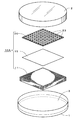
本発明の液体培地用足場部材10A及びその使用態様について、図1の分解斜視図を用いながら順に説明する。第1実施形態の液体培地用足場部材10Aは、シャーレ内に設置され、培養に供される使用例である。皿部1内に培養に必要な適量の液体培地3が注液される。そして、皿部1内に浸透台部11が備えられ、当該浸透台部11の直上に透過性膜部15が載置される。そして、透過性膜部15の直上にこの透過性膜部15と密着する区画培養部20が備えられる。区画培養部20は板体であり、その板体には貫通穴部23が形成されている。最終的には、皿部1を覆う蓋部2が被せられる。従って、図示の例の液体培地用足場部材10Aは、浸透台部11、透過性膜部15、及び区画培養部20を備えて構成される。
The liquid
浸透台部11は液体培地3と接触している。この液体培地3は浸透台部11内に毛細管現象により吸液されて行き渡り同浸透台部の全体に保持される。そのため、浸透性ある材質である限り特段限定されない。オートクレーブ等による加熱殺菌を考慮すると、耐熱性材料であることがより好ましい。液体培地用足場部材では、透過性膜部15の上面は液体培地3の液面よりも高い位置に置かれる(図3参照)。透過性膜部15上で培養されている生物種等の流出は抑えられることに加え、液体培地による水分過剰も抑制される。そこで、液体培地用足場部材10自体が液体培地3中に埋没することを避けるため、浸透台部11は適度な厚さが必要となる。例えば、所定厚さの脱脂綿、濾紙を重ねた板体、ポリウレタンのスポンジ状物である。加えて、綿、麻、羊毛等の織布、これら織布の重ね合わせも用いることができる。
The
さらに、浸透台部11は不織布から形成される。不織布は繊維の織り目を有せず不均一であるため、いったん吸液された後に毛細管現象を生じさせやすく、液体培地の吸収効率は高い。不織布の材質は繊維状物である限り広汎に使用可能である。例えば、ポリアミド繊維、ポリエステル繊維、アクリル樹脂、ポリエチレン繊維やポリプロピレン繊維の合成樹脂繊維等の不織布、さらにはフェルト生地が挙げられる。合成樹脂繊維は耐薬品性に優れて、安価かつ熱にも強い。また、フェルト生地も安価である。不織布への形成方法は公知手法が用いられ適宜である。
Further, the
その中でも、浸透台部11は再生セルロース繊維からなる不織布から形成される。再生セルロース繊維からなる不織布は、例えば、ビスコース法による不織布製造の場合、主に木材由来のパルプを水酸化ナトリウム等のアルカリ溶液に浸漬した後、二硫化炭素を添加して硫化し、さらにアルカリ溶解によりビスコースに調製して熟成後、硫酸等の酸溶液中へ繊維状に吐出するとともに重ね合わせる。そこで凝固反応が生じセルロースのみの繊維による布状物を得ることができる。再生セルロース繊維は全てセルロースから形成されるため、寒天のアガロースよりも培養対象となる生物種に与える影響が少ないと予想される。また、再生セルロース繊維からなる不織布は広汎に流通している素材であり、生物種に与える影響が少ない点で周知である。しかも、安価に調達することができる。
Among these, the
浸透台部11に載置される透過性膜部15は、オートクレーブ等による殺菌時の耐熱性とともに浸透台部11を通じて毛細管現象により吸液された液体培地の透過性を考慮した材料が選択される。具体的には、溶解している糖分(炭素源)、各種ペプトンや酵母エキス等の窒素源、塩類(各種金属成分)、その他、アミノ酸やビタミン類等の低分子化合物、成長促進因子や成長阻害因子、抗生物質等を透過させる性質が求められる。例えば、メンブレンフィルターや限外濾過膜等が挙げられる。これらでは膜の開孔を通じて培地の栄養成分が供給される。このため、供給される培地中の成分に偏りが生じることがある。また、過大に液体培地が供給されることによって、培養中の生物種が流出してしまうおそれもある。
For the
この点から、透過性膜部15には半透膜が用いられる。浸透台部11を通じて毛細管現象により吸液された液体培地を透過させる必要からである。半透膜は、前述のとおり、液体培地に溶解している各種の栄養成分等を膜全体に偏りなく透過させることが可能である。また、透過性膜部15上に接種、培養される生物種(微生物)が当該透過性膜部を通り抜けて浸透台部11に侵入することも抑制できる。半透膜の具体例として、アセチルセルロース膜、ポリアクリロニトリル膜、フッ素樹脂膜、ポリエステル系ポリマーアロイ膜、コラーゲン膜等が例示される。
From this point, a semipermeable membrane is used for the
前出のコラーゲン膜等の半透膜は高価格であり素材的に脆弱である。そこで、前述の透過性膜部15については、再生セルロースフィルムの半透膜、すなわちセロハンフィルムが用いられる。再生セルロースフィルムの半透膜(セロハンフィルム)は、前述の再生セルロース繊維からなる不織布と同じ構成成分である。ビスコースに調製して熟成後、硫酸等の酸溶液中へ膜状に吐出することによりフィルム化する点が異なるのみである。再生セルロースフィルムの半透膜(セロハンフィルム)も全てセルロースから形成されるため、寒天のアガロースよりも培養対象となる生物種に与える影響が少ないと予想される。特に、セロハンフィルムは低廉に入手できる利点が大きい。
The semipermeable membranes such as the above-mentioned collagen membranes are expensive and fragile. Therefore, for the
図示から明らかであるように、透過性膜部15と密着する区画培養部20は板状(板体)であり、貫通穴部23が複数個形成される。つまり、本発明の液体培地用足場部材10Aは公知の多穴のウェルプレート等を模した形態となる。そこで、培養対象の微生物や細胞は個々の貫通穴部23内の透過性膜部15上に播種(接種)される。そのため、貫通穴部23には一定の深さが必要である。区画培養部20の成型性、透過性膜部15との貼着作業の容易さ、部材自体の剛性(丈夫さ)等が考慮されて区画培養部20の板厚は規定される。この区画培養部20の板厚は、少なくとも0.4mm以上、好ましくは1mm以上、さらに好ましくは2mm前後である。区画培養部20の板厚の上限は特段制限されない。ただし、板厚を増し過ぎると後述する成型加工が難しくなる。また、浸透台部11の厚さも加わるため、液体培地用足場部材がシャーレ等に収まりきらなくなる。そのため、区画培養部20の板厚は概ね15mmが上限とされる。
As is clear from the drawing, the
区画培養部20は好ましくは樹脂製部材により形成される。樹脂製部材の加工時の利便性は高く、自在に貫通穴部を形成できる。区画培養部20の材質樹脂の種類には特段の制約は無い。一般に成型加工容易な樹脂種から選択される。区画培養部20は、オートクレーブ等による殺菌を考慮すると、容易に熱変形しない耐熱性樹脂から選択される。なお、ガンマ線殺菌等の場合には、特段の耐熱性までは必要とされない。
The
区画培養部20には、熱可塑性樹脂としては、ポリエチレン樹脂(高密度ポリエチレン樹脂、高分子量ポリエチレン)、ポリプロピレン樹脂、ポリエチレンテレフタレート(PET)樹脂、ポリアミド樹脂、ポリカーボネート樹脂、ポリ塩化ビニル樹脂、アクリル樹脂、ポリイミド樹脂、またはポリウレタン樹脂等が例示される。熱硬化性樹脂としては、フェノール樹脂、ジアリルフタレート樹脂、ユリア(尿素)樹脂、メラミン樹脂、エポキシ樹脂、シリコーン樹脂、ポリイミド樹脂、またはポリウレタン樹脂等が例示される。
The
ここで、相互間の接合等について述べる。透過性膜部15は浸透台部11に載置するだけでも、液体培地3の水分や栄養分が浸透する。従って、特段、相互間の接合までは要求されない。区画培養部20は透過性膜部15上に載置されるばかりではなく、相互に密着される。区画培養部20は複数の貫通穴部23を備えている。このため、一つの貫通穴部に播種された微生物が周囲の貫通穴部に入り込むと正確な実験を行うことができない。そこで、個々の貫通穴部同士を完全に独立させる必要があるためである。具体的には、図2の斜視図に示すように、接着剤30が区画培養部20の底面22に均等に塗布される。そして、透過性膜部15は区画培養部20の底面22に貼着される。符号21は区画培養部20の上面である。
Here, the joining between each other will be described. Even if the
接着剤30は、樹脂接着や加工に使用される樹脂系接着剤が使用される。接着剤30は、例えば、エポキシ樹脂系、アクリレート樹脂系、さらにはエチレン酢酸ビニル樹脂等の各種の樹脂成分から選択される。むろん、これら以外にも、十分な接着能力が発揮され、かつ殺菌時の耐熱性が充たされている種類であれば特段限定されない。ただし、培養対象となる生物種の生育に影響を与えない樹脂成分にする必要がある。 As the adhesive 30, a resin adhesive used for resin bonding or processing is used. The adhesive 30 is selected from various resin components such as an epoxy resin system, an acrylate resin system, and an ethylene vinyl acetate resin. Of course, other than these, there is no particular limitation as long as it is a kind that exhibits sufficient adhesive ability and is heat resistant during sterilization. However, it is necessary to use a resin component that does not affect the growth of the species to be cultured.
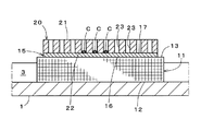
図3の部分縦断面の概略図は液体培地用足場部材10Aにおける皿部1、浸透台部11、透過性膜部15、及び区画培養部20の位置関係を示す。図示ではシャーレの蓋部2(図1参照)を省略している。シャーレの皿部1に浸透台部11の台底部12が接する。皿部1内の液体培地3は浸透台部11内に浸透して毛細管現象により台上部13まで到達する。浸透台部11の台上部13と透過性膜部15の膜部下面16は接しているため、液体培地は透過性膜部15も透過して膜部上面17に染み出す。そして、培地養分は区画培養部20の貫通穴部23に到達し、培養対象となる生物種は透過性膜部15を介して栄養分や塩類等を得ることができる。
The schematic diagram of the partial vertical cross-section of FIG. 3 shows the positional relationship between the
透過性膜部15は浸透台部11とともに安定し、しかも区画培養部20に透過性膜部15は貼着しているため、増殖のための足場となり得る。なお、透過性膜部15は浸透台部11に生育に影響を与えない成分のバインダ(接着剤)を用いて貼着してもよい。あるいは透過性膜部15自身の吸水に伴い浸透台部11と貼着される場合がある。再生セルロースフィルムの半透膜(セロハンフィルム)は液体培地の水分を吸収して湿潤化し、適度に粘性を帯びるため浸透台部との貼り付きも良くなる。この点からもセロハンフィルムは優れている。
Since the
図示の培養対象の生物種は微生物である。微生物のコロニーCが、区画培養部20の貫通穴部23内の透過性膜部15上の膜部上面17に複数形成されている。微生物は酵母、糸状菌等の真核生物に限らず、原核生物、古細菌、または未培養微生物も想定される。また、バクテリオファージに感染したE.coli.やBacillus sp.等のウイルス感染した菌類、遺伝子組み換えや遺伝子導入、その他の形質転換を行った菌類も想定される。特に、これまで未解明であったアガロースの影響を軽減したい場合に効果的である。また、好温菌、好熱菌等の高温培養条件下等、寒天培地の硬さを維持することができない状況下における培養にも有効である。むろん、培養対象となる生物種は微生物に限られることなく、動植物のプランクトン、原生動物、藻類、または動植物の組織細胞等も想定される。
The organism species to be cultured is a microorganism. A plurality of microorganism colonies C are formed on the
通常、一般的に使用されるような寒天培地を用いた培養では、経時的に培地自体を取り替えることは不可能である。しかし、液体培地の場合、培養途中での培地交換は容易である。従って、消費成分や生成産物等を分析し代謝等の経時的な変化を追跡する上でも都合良い。また、既に述べているように、寒天を用いない液体培地を使用しているにもかかわらず、透過性膜部により寒天培地の固体面を代用できる。このため、従前の寒天培地を用いた際と取り扱いやすさが大きく変わることなく、培養作業に従事する者の作業効率への影響は少ない。 Usually, in culture using an agar medium as commonly used, it is impossible to replace the medium itself over time. However, in the case of a liquid medium, medium exchange during the culture is easy. Therefore, it is convenient for analyzing consumption components, product products, etc., and tracking changes over time such as metabolism. Moreover, as already stated, although the liquid medium which does not use agar is used, the solid surface of the agar medium can be substituted by the permeable membrane part. For this reason, there is little influence on the work efficiency of those engaged in the culture work without greatly changing the ease of handling when using the conventional agar medium.
図4の模式図は、液体培地用足場部材10Aの使用事例である。図4(a)では、予め微生物等の生物種が区画培養部20の貫通穴部23内に播種(接種)され、同部位で培養されている。そこに、分注器具40により、溶液が個々の貫通穴部23内へ所定量注入(注液)される。分注用の溶液は任意であり、栄養液、抗生剤、染色液、抗体試薬、蛍光試薬、ラジオアイソトープ標識試薬等が挙げられる。分注対象の区画培養部20の貫通穴部23は、行と列の格子点上の配置であり、各配置は極めて規格化されている。後記の実施例においては、貫通穴部23は10行・10列の計100個形成(穿設)される。
The schematic diagram of FIG. 4 is a usage example of the liquid
図示の例の分注器具40は複数に分岐した先端を備えており、それぞれに交換チップ41が装着される。各交換チップ41内に溶液が保持可能である(マルチチャンネル対応型等)。図示の分注器具40の使用により、溶液は一度の処理で複数の貫通穴部23内へ注入される。当該分注処理は人手によるほか、クリーンベンチや安全キャビネット内に設置された作業ロボット等によっても実行可能である。従って、液体培地用足場部材10Aはハイスループット等の大規模処理にも有効に対応できる構造である。これにより、今まで以上に培養や単離の効率化が向上し得る。
The dispensing
図4(b)の模式図は区画培養部20の上面21を示す。液体培地用足場部材10Aを使用して微生物等の生物種を区画培養部20の貫通穴部23内に播種(接種)して培養した状態である。そこで、例えば、前掲図4(a)のとおり、貫通穴部23内に標識試薬または染色液等を分注した結果、いくつかの貫通穴部23において変色が生じたコロニー24である。図示から容易に理解されるように、液体培地用足場部材10Aは既存の多穴のウェルプレートに近似した形態を備えているため使い勝手がよい。例えば、液体培地用足場部材のまま、計測機器等に挿入したり保管したりすることもでき、作業の効率化が図られる。
The schematic diagram of FIG. 4B shows the
例えば、ある貫通穴部23内において優勢となって増殖した微生物は容易に隣接する貫通穴部23内と交雑し難くなる。従って、それぞれの貫通穴部23内に着目して分取と培養を繰り返すことによって比較的容易に目的とする微生物の単離が可能となり、スクリーニングの効率を高めることができる。さらには、同一の液体培地を共有しながら、区画培養部20の貫通穴部23内に異種の微生物を培養することもできる。
For example, microorganisms that have prevailed and proliferated in a certain through
加えて、図4(b)の模式図のとおり、区画培養部20の上面21に表示部27を備えることができる。表示部27は数字、アルファベット、さらには各種記号等から構成される。図示の例では、1ないし10の数字とAないしJのアルファベットとしている。表示部27は複数の貫通穴部23の位置を特定する際に利用される。
In addition, as shown in the schematic diagram of FIG. 4B, the
図5の斜視図は1個の液体培地用足場部材10Aを樹脂製の包装袋50内に収容して開口部分を封止した状態である。いわゆる、包装時及び販売時を想定した形態の一例である。このように包装袋内に収容して密封すると、液体培地用足場部材10Aの生物汚染が抑制される。また、包装袋50内に液体培地用足場部材10Aを収容した状態のまま、ガンマ線殺菌や加熱殺菌等の殺菌処理に供することも想定できる。従って、保管時等の清浄度は高いまま維持される。なお、包装袋50内の液体培地用足場部材10Aの収容数には制限はなく、使用規模に応じて適宜である。
The perspective view of FIG. 5 shows a state in which one liquid
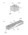
図6(a)は第2実施形態の液体培地用足場部材10Bの斜視図である。液体培地用足場部材10Bは浸透台部11、透過性膜部15、及び区画培養部20Bから構成される。これらは、既述の液体培地用足場部材10Aと同様である。ただし、区画培養部20Bの特徴として、貫通穴部23を1箇所のみ備える形態、大きさである。液体培地用足場部材10Bの用途としては、例えば、直径3cm程度のシャーレまたは6穴の培養プレート(ウェルプレート)等内に設置する使用が想定される。
FIG. 6A is a perspective view of the liquid
図6(b)は第3実施形態の液体培地用足場部材10Cの斜視図である。液体培地用足場部材10Cは浸透台部11、透過性膜部15、及び区画培養部20Cから構成される。これらも、液体培地用足場部材10Aと同様である。ただし、この例の区画培養部20Cは、前出の区画培養部20A、20Bとも異なる形状である。図示では、貫通穴部23が単列状に配置されている。第3実施形態の液体培地用足場部材10Cは、設置数を増減させることにより種々の大きさの培養容器に対応することができる。例えば、Tフラスコ等の口部分の狭小の容器内への出し入れも可能となる。
FIG. 6B is a perspective view of the liquid
[液体培地用足場部材の作製]
実施例1ないし7の液体培地用足場部材の作製に際し、浸透台部及び透過性膜部を共通とした。浸透台部として再生セルロース繊維からなる不織布(フタムラ化学株式会社製,TCF#408,合計の厚さ10mm)を使用し、透過性膜部として再生セルロースフィルムの半透膜、いわゆるセロハンフィルム(フタムラ化学株式会社製,PL#300,膜厚18μm)を使用した。
[Preparation of scaffold for liquid medium]
In producing the liquid medium scaffold members of Examples 1 to 7, the permeation platform and the permeable membrane were common. A non-woven fabric made of regenerated cellulose fibers (Futamura Chemical Co., Ltd., TCF # 408,
〈実施例1〉
立体造形装置(3Dプリンタ)と同装置に適合した専用アクリル樹脂を使用して、貫通穴部を10個×10個の格子点状に備えた板状物に形成した。硬化後の厚さは0.4mm、一辺5cmの正方形とし、貫通穴部の直径は3.8mmとした。こうして作製した区画培養部の裏面側に接着剤としてエポキシ樹脂(スコッチ社製,プレミアゴールドスーパー多用途)を塗工し、ここにセロハンフィルムを貼着した。そして、常温下にて静置し接着剤を硬化した。最終的に、浸透台部(再生セルロース繊維不織布)に、セロハンフィルム貼着済み区画培養部を重ね実施例1の液体培地用足場部材を得た。
<Example 1>
A dedicated acrylic resin suitable for the three-dimensional modeling apparatus (3D printer) and the same apparatus was used to form through holes in a plate-like object having 10 × 10 lattice points. The thickness after curing was 0.4 mm, a square with a side of 5 cm, and the diameter of the through hole was 3.8 mm. An epoxy resin (manufactured by Scotch, Premier Gold Super Versatile) was applied as an adhesive to the back side of the compartment culture section thus prepared, and a cellophane film was adhered thereto. And it stood still at normal temperature and the adhesive agent was hardened. Finally, the cell culture film-attached compartment culture part was overlapped on the permeation base part (regenerated cellulose fiber nonwoven fabric) to obtain a liquid medium scaffold member of Example 1.
〈実施例2〉
実施例1の立体造形装置(3Dプリンタ)と同装置に適合した専用ポリアミド樹脂(ナイロン樹脂)を使用して、貫通穴部を10個×10個の格子点状に備えた板状物に形成した。硬化後の厚さは0.5mm、一辺5cmの正方形とし、貫通穴部の直径は3.8mmとした。こうして作製した区画培養部の裏面側に実施例1と同一の接着剤を塗工し、ここにセロハンフィルムを貼着した。そして、常温下にて静置し接着剤を硬化した。最終的に、浸透台部(再生セルロース繊維不織布)に、セロハンフィルム貼着済み区画培養部を重ね実施例2の液体培地用足場部材を得た。
<Example 2>
Using the three-dimensional modeling apparatus (3D printer) of Example 1 and a dedicated polyamide resin (nylon resin) suitable for the same apparatus, through holes are formed in a plate-like object having 10 × 10 lattice points. did. The thickness after curing was 0.5 mm, a square with a side of 5 cm, and the diameter of the through hole was 3.8 mm. The same adhesive as in Example 1 was applied to the back side of the compartment culture part thus prepared, and a cellophane film was adhered thereto. And it stood still at normal temperature and the adhesive agent was hardened. Finally, the cell culture film-attached compartment culture part was overlapped on the permeation base part (regenerated cellulose fiber nonwoven fabric) to obtain a liquid medium scaffold member of Example 2.
〈実施例3〉
実施例1と同一のアクリル樹脂を用い、立体造形装置(3Dプリンタ)を使用して貫通穴部を10個×10個の格子点状に備えた板状物に形成した。硬化後の厚さは0.4mm、一辺5cmの正方形と、貫通穴部の直径は3.8mmとした。こうして作製した区画培養部の裏面側に接着剤としてエポキシ系の紫外線硬化樹脂(協立化学産業株式会社製,820SEL)を塗工し、ここにセロハンフィルムを貼着した。そして、常温下、紫外線を3000mJ/cm2の条件で照射して接着剤を硬化した。最終的に、浸透台部(再生セルロース繊維不織布)に、セロハンフィルム貼着済み区画培養部を重ね実施例3の液体培地用足場部材を得た。
<Example 3>
Using the same acrylic resin as in Example 1, a three-dimensional modeling apparatus (3D printer) was used to form through-holes on a plate-like object having 10 × 10 lattice points. The thickness after curing was 0.4 mm, the square with a side of 5 cm, and the diameter of the through hole was 3.8 mm. An epoxy ultraviolet curable resin (820SEL, manufactured by Kyoritsu Chemical Industry Co., Ltd.) was applied as an adhesive to the back side of the compartment culture section thus prepared, and a cellophane film was adhered thereto. And the ultraviolet-ray was irradiated on condition of 3000 mJ / cm < 2 > under normal temperature, and the adhesive agent was hardened. Finally, the cell culture film-attached compartment culture part was overlapped on the permeation base part (regenerated cellulose fiber nonwoven fabric) to obtain a liquid medium scaffold member of Example 3.
〈実施例4〉
実施例2と同一のポリアミド樹脂を用い、立体造形装置(3Dプリンタ)を使用して貫通穴部を10個×10個の格子点状に備えた板状物に形成した。硬化後の厚さは0.5mm、一辺5cmの正方形と、貫通穴部の直径は3.8mmとした。こうして作製した区画培養部の裏面側に接着剤として実施例3と共通の紫外線硬化樹脂を塗工し、ここにセロハンフィルムを貼着した。そして、常温下、実施例3と同一の条件下で紫外線を照射して接着剤を硬化した。最終的に、浸透台部(再生セルロース繊維不織布)に、セロハンフィルム貼着済み区画培養部を重ね実施例4の液体培地用足場部材を得た。
<Example 4>
The same polyamide resin as in Example 2 was used, and a three-dimensional modeling apparatus (3D printer) was used to form a through-hole portion in a plate-like object having 10 × 10 lattice points. The thickness after curing was 0.5 mm, a square with a side of 5 cm, and the diameter of the through hole was 3.8 mm. An ultraviolet curable resin common to Example 3 was applied as an adhesive on the back side of the compartment culture part thus prepared, and a cellophane film was adhered thereto. Then, the adhesive was cured by irradiating ultraviolet rays at room temperature under the same conditions as in Example 3. Finally, the cell culture film-attached compartment culture part was overlapped on the permeation base part (regenerated cellulose fiber nonwoven fabric) to obtain the liquid medium scaffold member of Example 4.
〈実施例5〉
実施例1と同一のアクリル樹脂を用い、立体造形装置(3Dプリンタ)を使用して貫通穴部を10個×10個の格子点状に備えた板状物に形成した。硬化後の厚さは2.0mm、一辺5cmの正方形と、貫通穴部の直径は3.8mmとした。こうして作製した区画培養部の裏面側に接着剤として実施例3と共通の紫外線硬化樹脂を塗工し、ここにセロハンフィルムを貼着した。そして、常温下、実施例3と同一の条件下で紫外線を照射して接着剤を硬化した。最終的に、浸透台部(再生セルロース繊維不織布)に、セロハンフィルム貼着済み区画培養部を重ね実施例5の液体培地用足場部材を得た。
<Example 5>
Using the same acrylic resin as in Example 1, a three-dimensional modeling apparatus (3D printer) was used to form through-holes on a plate-like object having 10 × 10 lattice points. The thickness after curing was 2.0 mm, the square with a side of 5 cm, and the diameter of the through hole was 3.8 mm. An ultraviolet curable resin common to Example 3 was applied as an adhesive on the back side of the compartment culture part thus prepared, and a cellophane film was adhered thereto. Then, the adhesive was cured by irradiating ultraviolet rays at room temperature under the same conditions as in Example 3. Finally, the cell culture film-attached compartment culture part was overlapped on the permeation base part (regenerated cellulose fiber nonwoven fabric) to obtain the liquid medium scaffold member of Example 5.
〈実施例6〉
実施例2と同一のポリアミド樹脂を用い、立体造形装置(3Dプリンタ)を使用して貫通穴部を10個×10個の格子点状に備えた板状物に形成した。硬化後の厚さは2.0mm、一辺5cmの正方形と、貫通穴部の直径は3.8mmとした。こうして作製した区画培養部の裏面側に接着剤として実施例3と共通の紫外線硬化樹脂を塗工し、ここにセロハンフィルムを貼着した。そして、常温下、実施例3と同一の条件下で紫外線を照射して接着剤を硬化した。最終的に、浸透台部(再生セルロース繊維不織布)に、セロハンフィルム貼着済み区画培養部を重ね実施例6の液体培地用足場部材を得た。
<Example 6>
The same polyamide resin as in Example 2 was used, and a three-dimensional modeling apparatus (3D printer) was used to form a through-hole portion in a plate-like object having 10 × 10 lattice points. The thickness after curing was 2.0 mm, the square with a side of 5 cm, and the diameter of the through hole was 3.8 mm. An ultraviolet curable resin common to Example 3 was applied as an adhesive on the back side of the compartment culture part thus prepared, and a cellophane film was adhered thereto. Then, the adhesive was cured by irradiating ultraviolet rays at room temperature under the same conditions as in Example 3. Finally, the cell culture film-attached compartment culture part was overlapped on the permeation base part (regenerated cellulose fiber nonwoven fabric) to obtain a liquid medium scaffold member of Example 6.
〈実施例7〉
実施例2と同一のポリアミド樹脂を用い、立体造形装置(3Dプリンタ)を使用して貫通穴部を10個×10個の格子点状に備えた板状物に形成した。硬化後の厚さは2.0mm、一辺5cmの正方形と、貫通穴部の直径は3.8mmとした。こうして作製した区画培養部の裏面側に接着剤としてポリオレフィン樹脂系のホットメルト樹脂(三洋貿易株式会社製,356P)を塗工し、ここにセロハンフィルムを貼着した。そして、常温下、静置して接着剤を硬化した。最終的に、浸透台部(再生セルロース繊維不織布)に、セロハンフィルム貼着済み区画培養部を重ね実施例7の液体培地用足場部材を得た。
<Example 7>
The same polyamide resin as in Example 2 was used, and a three-dimensional modeling apparatus (3D printer) was used to form a through-hole portion in a plate-like object having 10 × 10 lattice points. The thickness after curing was 2.0 mm, the square with a side of 5 cm, and the diameter of the through hole was 3.8 mm. A polyolefin resin-based hot melt resin (manufactured by Sanyo Trading Co., Ltd., 356P) was applied as an adhesive to the back side of the compartment culture section thus prepared, and a cellophane film was adhered thereto. And it stood still at normal temperature and the adhesive agent was hardened. Finally, the cell culture film-attached compartment culture part was stacked on the permeation base part (regenerated cellulose fiber nonwoven fabric) to obtain a liquid medium scaffold member of Example 7.
[作製結果]
実施例1,2の液体培地用足場部材は、薄い板厚ながら貫通穴部は深さを備えるため、穴状の機能を備える。なお、当該板厚(0.4mm)を下回ると区画培養部自体の樹脂成型、貼着加工等が難しくなることに加え、部材の耐久性も低下するおそれがある。そこで、少なくとも0.4mm以上の板厚は必要と想定した。
[Production results]
The scaffold members for liquid culture media of Examples 1 and 2 have a hole-like function because the through-hole portion has a depth despite being thin. In addition, when the thickness is less than 0.4 mm, it becomes difficult to perform resin molding and sticking processing of the compartment culture part itself, and the durability of the member may be reduced. Therefore, it was assumed that a plate thickness of at least 0.4 mm was necessary.
実施例3,4は接着剤の種類を変更した例である。特に、紫外線硬化樹脂としたことにより、区画培養部等に生じる撓み変形がより減少した。実施例1,2の液体培地用足場部材では、水分の影響からセロハンの変形を一部で確認した。 Examples 3 and 4 are examples in which the type of adhesive was changed. In particular, by using an ultraviolet curable resin, bending deformation generated in the compartment culture part or the like was further reduced. In the liquid medium scaffolds of Examples 1 and 2, deformation of cellophane was partially confirmed from the influence of moisture.
実施例5,6,7は区画培養部の板厚を厚くした例であり、区画培養部自体の剛性から変形はほとんどなく形状は最も安定している。また、これらの貫通穴部は十分な深さを備え、ピペット等による注入作業も容易であることから、良好な作業性が確保される。 Examples 5, 6, and 7 are examples in which the thickness of the compartment culture part is increased, and the shape is most stable with almost no deformation due to the rigidity of the compartment culture part itself. Moreover, since these through-hole parts have sufficient depth and the injection | pouring operation | work by a pipette etc. is easy, favorable workability | operativity is ensured.
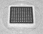
参考として実施例7の液体培地用足場部材を写真撮影した。図7の写真は、浸透台部(再生セルロース繊維不織布)にセロハンフィルム貼着済み区画培養部を重ねた実施例7の液体培地用足場部材を表し、かつ、全体をシャーレの皿部(内直径8.5cm)内に収容した状態である。写真上は見えにくいものの、行方向に1ないし10の数字、列方向にAないしJのアルファベットの表示部を凸状に形成した。なお、写真では上蓋、液体培地は省略した。
For reference, the liquid medium scaffold member of Example 7 was photographed. The photograph in FIG. 7 shows the scaffold member for liquid medium of Example 7 in which the cell culture film-attached compartment culture part is superimposed on the permeation base part (regenerated cellulose fiber nonwoven fabric), and the whole dish part (inner diameter) 8.5 cm). Although it is difficult to see on the photograph,
[採取と培養]
発明者らは液体培地用足場部材の実効性を検証するべく、培養生物種を微生物として培養を試みた。検証の微生物は国立大学法人筑波大学(茨城県つくば市内)の大学構内の池水から採取した。
[Collection and culture]
The inventors tried to culture using a culture species as a microorganism in order to verify the effectiveness of the liquid medium scaffold member. The verified microorganisms were collected from the pond water on the university campus of the University of Tsukuba (Tsukuba City, Ibaraki Prefecture).
液体培地用足場部材には、実施例7を使用した。浸透台部(再生セルロース繊維不織布)をオートクレーブにより加熱殺菌した。同様に、セロハンフィルム貼着済み区画培養部もオートクレーブにより加熱殺菌した。こうして、部材毎に分けることによって実施例7の液体培地用足場部材の全ての部材を殺菌した。 Example 7 was used for the liquid medium scaffold member. The permeation base (regenerated cellulose fiber nonwoven fabric) was sterilized by heating with an autoclave. Similarly, the cell culture section with cellophane film attached was also sterilized by heating in an autoclave. In this way, all members of the liquid medium scaffold member of Example 7 were sterilized by dividing each member.
液体培地はR2A粉末培地(日本製薬株式会社製)を仕様の濃度に調製して使用した。当該液体培地を滅菌済みプラスチックシャーレ(内直径8.5cm)内に所定量ずつ分注した。ただし、シャーレ内の液体培地の液面は液体培地用足場部材の浸透台部の台上部よりも低い適切な位置とした。 As the liquid medium, an R2A powder medium (manufactured by Nippon Pharmaceutical Co., Ltd.) was prepared to a specified concentration and used. The liquid medium was dispensed into a sterilized plastic petri dish (inner diameter 8.5 cm) by a predetermined amount. However, the liquid surface of the liquid medium in the petri dish was set to an appropriate position lower than the upper part of the permeation base part of the liquid medium scaffold member.
前出の大学構内にて採取した池水を滅菌水により適宜希釈した。分注器具(ギルソン社製,ピペットマン)を使用してこの希釈水を2μLずつ、実施例7の液体培地用足場部材の全ての貫通穴部内底部の再生セルロースフィルムの半透膜(セロハンフィルム)に分注し、接種操作とした。その後、シャーレの上蓋を被せて加湿状態で30℃、48時間、インキュベータを用いて培養した。 The pond water collected at the above university campus was appropriately diluted with sterilized water. Using a dispensing device (Gilson, Pipetteman), 2 μL of this diluted water was applied to the semipermeable membrane (cellophane film) of the regenerated cellulose film at the inner bottom of all through-hole portions of the liquid medium scaffold member of Example 7. Dispensing and inoculating. Then, the petri dish was covered with an upper lid and cultured in an incubator at 30 ° C. for 48 hours in a humidified state.
前述の培養後、液体培地用足場部材を目視により観察した。変色した貫通穴部は増殖した微生物のコロニーであった。このことから、微生物の培養に有効であることを確認した。液体培地用足場部材では、微生物の播種(接種)の作業に既存の分注器具を使用でき、しかも、貫通穴部は規格化された格子点状の配置であることから、分注等の連続操作にも適する。それゆえ、液体培地用足場部材のハイスループット処理へ期待は大きい。さらに、寒天等のゲル状の培地を調製する必要はなく、液体培地のまま培養することができる。従って、培地調製の簡素化とともに、全体的な作業効率の向上に貢献できる。 After the above culture, the liquid medium scaffold member was visually observed. The discolored through hole was a colony of grown microorganisms. From this, it was confirmed that it is effective for culturing microorganisms. In the liquid medium scaffold member, existing dispensing devices can be used for the inoculation (inoculation) of microorganisms, and the through-holes are arranged in a standard lattice point, so continuous dispensing etc. Suitable for operation. Therefore, expectation is high for the high-throughput processing of the liquid medium scaffold member. Furthermore, it is not necessary to prepare a gel-like medium such as agar, and the medium can be cultured in a liquid medium. Therefore, it is possible to contribute to the improvement of the overall working efficiency as well as the simplification of the medium preparation.
本発明の液体培地用足場部材を採用することにより、液体培地のみでも、比較的安価かつ簡便に培養が簡単にできることを示した。そこで、寒天培地の代替としての意義が大きく、規模拡大による産業上の利用可能性は大いに期待できる。加えて、部材を規格品化することで自動化処理への適用も可能であり、従前の寒天培地では生育することができなかった難培養性微生物等の未利用生物資源の研究をより活性化できる。 It has been shown that by employing the liquid medium scaffold member of the present invention, it is possible to cultivate relatively easily at a relatively low cost using only the liquid medium. Therefore, it has great significance as an alternative to an agar medium, and industrial applicability due to scale expansion can be greatly expected. In addition, it is possible to apply to automated processing by standardizing parts, and it is possible to further activate research on unused biological resources such as difficult-to-cultivate microorganisms that could not grow on conventional agar media .
1 シャーレの皿部
2 シャーレの蓋部
3 液体培地
10A,10B,10C 液体培地用足場部材
11 浸透台部
12 台底部
13 台上部
15 透過性膜部
16 膜部下面
17 膜部上面
20,20B,20C 区画培養部
21 区画培養部の上面
22 区画培養部の下面
23 貫通穴部
27 表示部
30 接着剤
40 分注器具
50 包装袋
C 微生物のコロニー
DESCRIPTION OF
Claims (8)
前記浸透台部に載置され前記浸透台部に吸液された前記液体培地を透過させる半透膜の透過性膜部と、
前記透過性膜部と密着する板体であって前記板体に貫通穴部が形成されている区画培養部とを備える
ことを特徴とする液体培地用足場部材。 A permeation stand that contacts the liquid medium and absorbs and holds the liquid medium;
A semipermeable membrane permeable membrane portion that is placed on the osmosis table portion and allows the liquid medium that has been absorbed into the osmosis table portion to pass therethrough;
A scaffold member for a liquid medium, comprising: a plate body that is in close contact with the permeable membrane portion, wherein the plate body is formed with a through-hole portion.
Priority Applications (1)
| Application Number | Priority Date | Filing Date | Title |
|---|---|---|---|
| JP2015128799A JP6792770B2 (en) | 2015-06-26 | 2015-06-26 | Scaffolding member for liquid medium |
Applications Claiming Priority (1)
| Application Number | Priority Date | Filing Date | Title |
|---|---|---|---|
| JP2015128799A JP6792770B2 (en) | 2015-06-26 | 2015-06-26 | Scaffolding member for liquid medium |
Publications (2)
| Publication Number | Publication Date |
|---|---|
| JP2017012005A true JP2017012005A (en) | 2017-01-19 |
| JP6792770B2 JP6792770B2 (en) | 2020-12-02 |
Family
ID=57827300
Family Applications (1)
| Application Number | Title | Priority Date | Filing Date |
|---|---|---|---|
| JP2015128799A Expired - Fee Related JP6792770B2 (en) | 2015-06-26 | 2015-06-26 | Scaffolding member for liquid medium |
Country Status (1)
| Country | Link |
|---|---|
| JP (1) | JP6792770B2 (en) |
Cited By (1)
| Publication number | Priority date | Publication date | Assignee | Title |
|---|---|---|---|---|
| WO2018138935A1 (en) * | 2017-01-25 | 2018-08-02 | パナソニックIpマネジメント株式会社 | Method for determining whether or not test sample contains phytopathogenic fungus |
Citations (8)
| Publication number | Priority date | Publication date | Assignee | Title |
|---|---|---|---|---|
| JPS55108284A (en) * | 1979-01-19 | 1980-08-20 | Peters J Hinrich | Bilogical container |
| JP2005027598A (en) * | 2003-07-09 | 2005-02-03 | Kitakyushu Foundation For The Advancement Of Industry Science & Technology | CELL CULTURE CHIP AND CULTURE DEVICE, CELL CULTURE METHOD USING THE SAME, CELL CARRIER MODULE SUPPORTING Spherical Cell Organization, Spherical Cell Organization |
| JP2005233641A (en) * | 2004-02-17 | 2005-09-02 | National Institute Of Advanced Industrial & Technology | Compartment array type extracellular potential measurement probe |
| JP2006333727A (en) * | 2005-05-31 | 2006-12-14 | National Cardiovascular Center | Scaffold sheet and manufacturing method thereof |
| JP2010263868A (en) * | 2009-05-18 | 2010-11-25 | Covalent Materials Corp | Cell culture carrier |
| JP2010273655A (en) * | 2009-05-29 | 2010-12-09 | Canon Inc | Cell holding method, cell testing method and cell processing apparatus |
| JP2012200152A (en) * | 2011-03-23 | 2012-10-22 | Futamura Chemical Co Ltd | Scaffolding member for liquid medium |
| JP2015019587A (en) * | 2013-07-16 | 2015-02-02 | 大日本印刷株式会社 | Method for producing cell culture substrate |
-
2015
- 2015-06-26 JP JP2015128799A patent/JP6792770B2/en not_active Expired - Fee Related
Patent Citations (8)
| Publication number | Priority date | Publication date | Assignee | Title |
|---|---|---|---|---|
| JPS55108284A (en) * | 1979-01-19 | 1980-08-20 | Peters J Hinrich | Bilogical container |
| JP2005027598A (en) * | 2003-07-09 | 2005-02-03 | Kitakyushu Foundation For The Advancement Of Industry Science & Technology | CELL CULTURE CHIP AND CULTURE DEVICE, CELL CULTURE METHOD USING THE SAME, CELL CARRIER MODULE SUPPORTING Spherical Cell Organization, Spherical Cell Organization |
| JP2005233641A (en) * | 2004-02-17 | 2005-09-02 | National Institute Of Advanced Industrial & Technology | Compartment array type extracellular potential measurement probe |
| JP2006333727A (en) * | 2005-05-31 | 2006-12-14 | National Cardiovascular Center | Scaffold sheet and manufacturing method thereof |
| JP2010263868A (en) * | 2009-05-18 | 2010-11-25 | Covalent Materials Corp | Cell culture carrier |
| JP2010273655A (en) * | 2009-05-29 | 2010-12-09 | Canon Inc | Cell holding method, cell testing method and cell processing apparatus |
| JP2012200152A (en) * | 2011-03-23 | 2012-10-22 | Futamura Chemical Co Ltd | Scaffolding member for liquid medium |
| JP2015019587A (en) * | 2013-07-16 | 2015-02-02 | 大日本印刷株式会社 | Method for producing cell culture substrate |
Cited By (2)
| Publication number | Priority date | Publication date | Assignee | Title |
|---|---|---|---|---|
| WO2018138935A1 (en) * | 2017-01-25 | 2018-08-02 | パナソニックIpマネジメント株式会社 | Method for determining whether or not test sample contains phytopathogenic fungus |
| JPWO2018138935A1 (en) * | 2017-01-25 | 2020-01-16 | パナソニックIpマネジメント株式会社 | Method for determining whether a test sample contains phytopathogenic fungi |
Also Published As
| Publication number | Publication date |
|---|---|
| JP6792770B2 (en) | 2020-12-02 |
Similar Documents
| Publication | Publication Date | Title |
|---|---|---|
| US8841122B2 (en) | Systems and methods for expanding high density non-adherent cells | |
| US20090148941A1 (en) | Disposable mini-bioreactor device and method | |
| US20060014274A1 (en) | Fiber cassette and modularly designed cassette system | |
| FI131135B1 (en) | Microfluidic cell culture device and method for cell cultivation | |
| JP2014132869A (en) | Cell culture vessel | |
| CN102057033A (en) | Scalable cell culture bioreactor and cell culture process | |
| JP6715330B2 (en) | Cell three-dimensional structuring method and three-dimensional structuring system | |
| CN103710263A (en) | cell culture device | |
| CN104498322A (en) | In-situ high flux culture apparatus for sea microbe | |
| JP4668568B2 (en) | Culturing container, culturing apparatus, and cell culturing method | |
| CN102703318A (en) | Multi-chamber co-culture device | |
| CN109906267B (en) | Micro Bioreactor Components | |
| JP6792770B2 (en) | Scaffolding member for liquid medium | |
| JP5868601B2 (en) | Scaffolding material for liquid medium | |
| JPH11509420A (en) | Dialysis multiple well tissue culture plate | |
| JPWO2016140213A1 (en) | Cell culture method using hollow fiber module | |
| FI129674B (en) | Apparatus and method for cell cultivation | |
| KR101395205B1 (en) | Micro culture dish, and method for cell culture using the same | |
| JP2005218368A (en) | Apparatus for culturing cell | |
| JP6501255B2 (en) | Culture apparatus and cell culture method using the culture apparatus | |
| JP2015167550A (en) | Cell cultivation device | |
| US20240400961A1 (en) | Cell sheet bioreactor | |
| JP2019097478A (en) | Methods of cell collection | |
| JP2004248628A (en) | High efficiency bioreactor system | |
| WO2025191281A2 (en) | Fluidic bioculture system |
Legal Events
| Date | Code | Title | Description |
|---|---|---|---|
| A521 | Request for written amendment filed |
Free format text: JAPANESE INTERMEDIATE CODE: A523 Effective date: 20150708 |
|
| A621 | Written request for application examination |
Free format text: JAPANESE INTERMEDIATE CODE: A621 Effective date: 20180528 |
|
| A521 | Request for written amendment filed |
Free format text: JAPANESE INTERMEDIATE CODE: A821 Effective date: 20180528 |
|
| A977 | Report on retrieval |
Free format text: JAPANESE INTERMEDIATE CODE: A971007 Effective date: 20190329 |
|
| A131 | Notification of reasons for refusal |
Free format text: JAPANESE INTERMEDIATE CODE: A131 Effective date: 20190514 |
|
| A521 | Request for written amendment filed |
Free format text: JAPANESE INTERMEDIATE CODE: A523 Effective date: 20190702 |
|
| A131 | Notification of reasons for refusal |
Free format text: JAPANESE INTERMEDIATE CODE: A131 Effective date: 20200121 |
|
| A521 | Request for written amendment filed |
Free format text: JAPANESE INTERMEDIATE CODE: A523 Effective date: 20200306 |
|
| TRDD | Decision of grant or rejection written | ||
| A01 | Written decision to grant a patent or to grant a registration (utility model) |
Free format text: JAPANESE INTERMEDIATE CODE: A01 Effective date: 20200915 |
|
| A61 | First payment of annual fees (during grant procedure) |
Free format text: JAPANESE INTERMEDIATE CODE: A61 Effective date: 20201013 |
|
| R150 | Certificate of patent or registration of utility model |
Ref document number: 6792770 Country of ref document: JP Free format text: JAPANESE INTERMEDIATE CODE: R150 |
|
| R250 | Receipt of annual fees |
Free format text: JAPANESE INTERMEDIATE CODE: R250 |
|
| LAPS | Cancellation because of no payment of annual fees |