JP2017012025A - Greening unit device and planting unit - Google Patents
Greening unit device and planting unit Download PDFInfo
- Publication number
- JP2017012025A JP2017012025A JP2015129499A JP2015129499A JP2017012025A JP 2017012025 A JP2017012025 A JP 2017012025A JP 2015129499 A JP2015129499 A JP 2015129499A JP 2015129499 A JP2015129499 A JP 2015129499A JP 2017012025 A JP2017012025 A JP 2017012025A
- Authority
- JP
- Japan
- Prior art keywords
- unit
- planting
- greening
- units
- flow path
- Prior art date
- Legal status (The legal status is an assumption and is not a legal conclusion. Google has not performed a legal analysis and makes no representation as to the accuracy of the status listed.)
- Pending
Links
- XLYOFNOQVPJJNP-UHFFFAOYSA-N water Substances O XLYOFNOQVPJJNP-UHFFFAOYSA-N 0.000 claims description 79
- 238000003973 irrigation Methods 0.000 claims description 33
- 230000002262 irrigation Effects 0.000 claims description 33
- 238000009434 installation Methods 0.000 claims description 21
- 230000008878 coupling Effects 0.000 claims description 2
- 238000010168 coupling process Methods 0.000 claims description 2
- 238000005859 coupling reaction Methods 0.000 claims description 2
- 230000005465 channeling Effects 0.000 claims 2
- 238000003466 welding Methods 0.000 description 4
- 238000010586 diagram Methods 0.000 description 2
- 230000000694 effects Effects 0.000 description 2
- 239000011521 glass Substances 0.000 description 2
- 238000005507 spraying Methods 0.000 description 2
- 239000008400 supply water Substances 0.000 description 2
- 230000001276 controlling effect Effects 0.000 description 1
- 230000007423 decrease Effects 0.000 description 1
- 230000002542 deteriorative effect Effects 0.000 description 1
- 238000005516 engineering process Methods 0.000 description 1
- 230000001771 impaired effect Effects 0.000 description 1
- 238000012986 modification Methods 0.000 description 1
- 230000004048 modification Effects 0.000 description 1
- 230000006798 recombination Effects 0.000 description 1
- 238000005215 recombination Methods 0.000 description 1
- 230000001105 regulatory effect Effects 0.000 description 1
- 230000003014 reinforcing effect Effects 0.000 description 1
- 125000006850 spacer group Chemical group 0.000 description 1
Images





Landscapes
- Cultivation Of Plants (AREA)
- Cultivation Receptacles Or Flower-Pots, Or Pots For Seedlings (AREA)
Abstract
Description
この発明は、緑化ユニット装置および植栽ユニットに関し、例えば、オフィス等の室内の一部を簡易に緑化し得る技術に関する。 The present invention relates to a greening unit device and a planting unit, for example, to a technology that can easily green a part of a room such as an office.
オフィス等の室内に設置する室内緑化装置が提案されている(特許文献1)。この室内緑化装置は緑化園を収納する収納ケースを備え、この収納ケースに水を供給する水供給パイプが連結されている。この水供給パイプに、前記緑化園に水を散布する水散布装置を備えている。 An indoor greening device installed in a room such as an office has been proposed (Patent Document 1). This indoor greening device is provided with a storage case for storing a green garden, and a water supply pipe for supplying water to the storage case is connected thereto. The water supply pipe is provided with a water spraying device for spraying water to the green garden.
従来の室内緑化装置では、例えば、複数の収納ケースを上下左右に複数組み合わせて互いに固定した緑化ユニット装置は開示されていない。仮に、複数の収納ケースを上下左右に複数組み合わせて固定しようとすると、次のような問題がある。複数の水供給パイプを準備しておき、使用者の好みに合わせて収納ケースの組み合わせパターンが変わる都度、水供給パイプを敷設し直す等の手間がかかりコスト高となる。 In a conventional indoor greening device, for example, a greening unit device in which a plurality of storage cases are combined in a vertical and horizontal direction and fixed to each other is not disclosed. If a plurality of storage cases are combined and fixed in the vertical and horizontal directions, there are the following problems. Each time a plurality of water supply pipes are prepared and the combination pattern of the storage case changes according to the user's preference, it takes time and labor to re-install the water supply pipes, resulting in high costs.
この発明の目的は、複数の植栽ユニットを簡易に組み合わせて使用することができる緑化ユニット装置および植栽ユニットを提供することである。 An object of the present invention is to provide a greening unit device and a planting unit that can be used by simply combining a plurality of planting units.
この発明の緑化ユニット装置は、植物を設置する植栽ユニットを上下左右に複数組み合わせた緑化ユニット装置であって、
組替え可能な前記複数の植栽ユニットと、
これら植栽ユニットを組み合わせて互いに固定可能なユニット固定手段と、
このユニット固定手段で固定された各植栽ユニットにそれぞれ灌水を行う灌水手段と、
を備え、
前記各植栽ユニットは、それぞれ正面が窓とされた箱状とされ底部に植物が設置されることを特徴とする。
The greening unit device of the present invention is a greening unit device that combines a plurality of planting units for installing plants vertically and horizontally,
A plurality of planting units that can be recombined;
Unit fixing means that can be fixed together by combining these planting units;
Irrigation means for irrigating each planting unit fixed by the unit fixing means,
With
Each of the planting units has a box shape with a front window, and a plant is installed at the bottom.
この構成によると、複数の植栽ユニットを使用者等の好みに合わせて自由に組替え、ユニット固定手段は、これら植栽ユニットを組み合わせて固定し得る。灌水手段は、各植栽ユニットにそれぞれ灌水を行う。このように植栽ユニットを自由に組替えてユニット固定手段で固定できるため、複数の植栽ユニットを簡易に組み合わせて使用することができる。各植栽ユニットは、正面が窓とされた箱状とされ底部に植物が設置される。前記窓は開放されていても良いし、前記窓に透明な光透過性部材(ガラス等)や開閉扉等を備えていても良い。窓が開放されている場合や開閉扉等を備えている場合、使用者等は、植物を直接鑑賞することができるうえ、各植栽ユニットに対して植物を設置または交換することが容易に行える。
このような緑化ユニット装置をオフィス等の室内に設けることで、室内空間の価値の向上を図ることができる。
According to this configuration, a plurality of planting units can be freely rearranged according to the user's preference, and the unit fixing means can fix these planting units in combination. The irrigation means irrigates each planting unit. Thus, since a planting unit can be freely rearranged and fixed with a unit fixing means, a plurality of planting units can be easily combined and used. Each planting unit is shaped like a box with a window on the front, and plants are installed at the bottom. The window may be opened, or the window may be provided with a transparent light transmissive member (glass or the like), an opening / closing door, or the like. When the window is open or equipped with an open / close door, etc., the user can directly appreciate the plant and can easily install or replace the plant for each planting unit. .
By providing such a greening unit device in a room such as an office, the value of the indoor space can be improved.
前記灌水手段は、水を貯留するタンクおよびこのタンクに貯留された水を各植栽ユニットに供給するポンプを有する灌水ユニットと、前記ポンプで吸い上げた水を複数の植栽ユニットにそれぞれ導く流路とを備えたものとしても良い。このようにタンクに貯留した水をポンプで吸い上げて流路を介して複数の植栽ユニットにそれぞれ導くことで、植物を管理、世話する管理者の作業負担の低減を図ることができる。 The irrigation means includes an irrigation unit having a tank for storing water and a pump for supplying the water stored in the tank to each planting unit, and a flow path for guiding the water sucked up by the pump to a plurality of planting units. It is good also as having. In this way, the water stored in the tank is sucked up by a pump and guided to the plurality of planting units through the flow path, thereby reducing the work load on the manager who manages and cares for the plant.
前記前記各植栽ユニットに前記流路が設けられ、この流路は、前記各植栽ユニットに水を導く流路部分と、前記各植栽ユニットに隣接する次段の植栽ユニットに水を導く流路部分とを有するものとしても良い。このように各植栽ユニットの流路が、各植栽ユニットに水を導く流路部分と、次段の植栽ユニットに水を導く流路部分とを有するため、複数の植栽ユニットを自由に組替えることができる。したがって、複数の植栽ユニットの組み合わせのバリエーションを多くして、使用者等の要求に沿う形状の緑化ユニット装置を容易に実現できる。 Each of the planting units is provided with the channel, and the channel is configured to supply water to a channel portion that guides water to the planting units, and to the next-stage planting unit adjacent to the planting units. It is good also as what has a flow-path part to guide. Thus, since the flow path of each planting unit has a flow path part for guiding water to each planting unit and a flow path part for guiding water to the next-stage planting unit, a plurality of planting units can be freely set. Can be rearranged. Therefore, the variation of the combination of several planting units can be increased, and the greening unit apparatus of the shape which meets a user's etc. request | requirement is easily realizable.
前記灌水手段は、各植栽ユニットへの給水量を調整する給水量調整手段を有するものとしても良い。ポンプから各植栽ユニットへの流路の長さが異なることに起因する管路抵抗の変化等により、各植栽ユニットへの給水量が不所望に異なる場合がある。また設置した植物の種類によっては給水量を個別に調整したい場合がある。このような場合に給水量調整手段により各植栽ユニットへの給水量を適量に調整し得る。 The irrigation means may have water supply amount adjusting means for adjusting the water supply amount to each planting unit. The amount of water supplied to each planting unit may differ undesirably due to changes in pipe resistance caused by the different lengths of the channels from the pump to each planting unit. Depending on the type of plant installed, you may want to adjust the water supply individually. In such a case, the water supply amount to each planting unit can be adjusted to an appropriate amount by the water supply amount adjusting means.
前記各植栽ユニットは、上下方向に延びる複数の柱部を有し、いずれかの柱部における内側面部に沿って前記流路を設けても良い。この場合、緑化ユニット装置の外観上、流路を目立たないように処理して植物を鑑賞し得る。
前記灌水手段は、上または下に隣接する植栽ユニットに設けた流路同士を繋ぐ継手を有するものとしても良い。この場合、様々な植栽ユニットの上下の組み合わせに対応することが可能となる。したがって、複数の植栽ユニットの組み合わせのバリエーションを多くして、使用者等の要求に沿う形状の緑化ユニット装置を容易に実現できる。
Each of the planting units may have a plurality of pillar portions extending in the up-down direction, and the flow path may be provided along an inner side surface portion of any pillar portion. In this case, in view of the appearance of the greening unit device, it is possible to appreciate the plant by processing the channel so as not to stand out.
The said irrigation means is good also as what has a joint which connects the flow paths provided in the planting unit which adjoins up or down. In this case, it becomes possible to correspond to the upper and lower combinations of various planting units. Therefore, the variation of the combination of several planting units can be increased, and the greening unit apparatus of the shape which meets a user's etc. request | requirement is easily realizable.
前記柱部における内側面部には、前記流路を覆うカバー部材を設けても良い。流路が露出すると美観を損ねることが懸念される。この構成によると、柱部に沿って設けた流路をカバー部材で覆うことで、流路が露出することを防止することができる。
前記ユニット固定手段は、上下に隣接する植栽ユニットを互いに位置決めして組み合わせる位置決め手段を含むものとしても良い。この場合、植栽ユニットを上下に組み合わせるとき、位置決め手段で互いに位置決めして組み合わせることができ、組立てを簡単化することができる。
A cover member that covers the flow path may be provided on the inner side surface portion of the column portion. If the flow path is exposed, there is a concern that the aesthetic appearance may be impaired. According to this structure, it can prevent that a flow path is exposed by covering the flow path provided along the pillar part with a cover member.
The unit fixing means may include positioning means for positioning and combining planting units adjacent vertically to each other. In this case, when the planting units are combined up and down, they can be positioned and combined with each other by the positioning means, and assembly can be simplified.
この発明の植栽ユニットは、複数組替え可能に組み合わせる植栽ユニットであって、
有底の箱状に形成され植物が設置されるプランタ設置部と、
このプランタ設置部における上縁部から上下方向に延びる複数の柱部と、
これら柱部の上端部を繋ぐ水平方向に延びる複数の連結部とで正面が窓とされた箱状とされ且つ流路を有し、
この流路は、前記プランタ設置部に設置された植物に水を導く流路部分と、この植栽ユニットに隣接して組み合わせられる植栽ユニットに水を導く流路部分とを有する。
The planting unit of the present invention is a planting unit that can be combined in multiple ways,
A planter installation part in which a plant is installed in a box shape with a bottom;
A plurality of pillars extending vertically from the upper edge in the planter installation part;
A plurality of connecting portions extending in the horizontal direction connecting the upper end portions of these pillar portions are box-shaped with a front face as a window and have a flow path,
This flow path has a flow path part for guiding water to the plant installed in the planter installation part, and a flow path part for guiding water to a planting unit combined adjacent to the planting unit.
この構成によると、複数の植栽ユニットを使用者等の好みに合わせて自由に組替えて組み合わせて使用することができる。前記窓は開放されていても良いし、前記窓に透明な光透過性部材(ガラス等)や開閉扉等を備えていても良い。窓が開放されている場合や開閉扉等を備えている場合、使用者等は、植物を直接鑑賞することができるうえ、各植栽ユニットに対して植物を設置または交換することが容易に行える。
流路は、プランタ設置部に設置された植物に水を導く流路部分と、この植栽ユニットに隣接して組み合わせられる植栽ユニットに水を導く流路部分とを有するため、複数の植栽ユニットを自由に且つ簡易に組替えることができる。したがって、複数の植栽ユニットの組み合わせのバリエーションを多くして、使用者等の要求に沿う形状を容易に実現できる。
According to this configuration, a plurality of planting units can be freely rearranged and combined according to the user's preference. The window may be opened, or the window may be provided with a transparent light transmissive member (glass or the like), an opening / closing door, or the like. When the window is open or equipped with an open / close door, etc., the user can directly appreciate the plant and can easily install or replace the plant for each planting unit. .
Since the flow path has a flow path portion for guiding water to a plant installed in the planter installation portion and a flow path portion for guiding water to a planting unit combined adjacent to the planting unit, a plurality of planting Units can be rearranged freely and easily. Therefore, the variation in combination of a plurality of planting units can be increased, and a shape that meets the demands of the user can be easily realized.
この発明の緑化ユニット装置は、植物を設置する植栽ユニットを上下左右に複数組み合わせた緑化ユニット装置であって、組替え可能な前記複数の植栽ユニットと、これら植栽ユニットを組み合わせて互いに固定可能なユニット固定手段と、このユニット固定手段で固定された各植栽ユニットにそれぞれ灌水を行う灌水手段とを備える。前記各植栽ユニットは、それぞれ正面が窓とされた箱状とされ底部に植物が設置される。このため、複数の植栽ユニットを簡易に組み合わせて使用することができる。
この発明の緑化ユニット装置は、複数組替え可能に組み合わせる植栽ユニットであって、有底の箱状に形成され植物が設置されるプランタ設置部と、このプランタ設置部における上縁部から上下方向に延びる複数の柱部と、これら柱部の上端部を繋ぐ水平方向に延びる複数の連結部とで正面が窓とされた箱状とされ且つ流路を有し、この流路は、前記プランタ設置部に設置された植物に水を導く流路部分と、この植栽ユニットに隣接して組み合わせられる植栽ユニットに水を導く流路部分とを有する。このため、複数の植栽ユニットを簡易に組み合わせて使用することができる。
The planting unit device of the present invention is a planting unit device in which a plurality of planting units for installing plants are vertically and horizontally combined, and the plurality of planting units that can be rearranged and these planting units can be combined and fixed to each other. Unit fixing means and irrigation means for irrigating each planting unit fixed by the unit fixing means. Each planting unit has a box-like shape with a front window, and a plant is installed at the bottom. For this reason, a plurality of planting units can be used in a simple combination.
The planting unit of the present invention is a planting unit that can be combined in a plurality of recombination units, and is formed in a bottomed box shape and a planter is installed in a vertical direction from an upper edge in the planter installation unit. A plurality of pillars extending and a plurality of connecting parts extending in the horizontal direction connecting the upper ends of these pillars are formed in a box shape with a front face as a window and have a flow path. A channel portion for guiding water to a plant installed in the section, and a channel portion for guiding water to a planting unit combined adjacent to the planting unit. For this reason, a plurality of planting units can be used in a simple combination.
この発明の実施形態に係る緑化ユニット装置を図1ないし図12と共に説明する。この緑化ユニット装置は、例えば、オフィス等の室内の一部に設置される。但し、この緑化ユニット装置は、室内のみに限定して設置されるものではなく、例えば、駅や空港等のコンコース等に設置しても良い。 A greening unit device according to an embodiment of the present invention will be described with reference to FIGS. This greening unit device is installed in a part of a room such as an office. However, this greening unit device is not limited to being installed only indoors, and may be installed, for example, in a concourse such as a station or an airport.
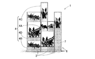
図1はこの緑化ユニット装置1の正面図であり、図2はこの緑化ユニット装置1の斜視図である。図1および図2に示すように、緑化ユニット装置1は、植物2を設置する植栽ユニット等を上下左右に複数組み合わせた装置である。この緑化ユニット装置1は、ベースユニット3と、複数の植栽ユニット4と、ユニット固定手段5(図4,図5)と、灌水手段6とを備える。
FIG. 1 is a front view of the
ベースユニット3、植栽ユニット4について説明する。
ベースユニット3は、その外形が平面視略矩形状で床面に設置される。このベースユニット3は、構成する植栽ユニット4の左右方向A1の列数に合わせて、左右方向A1に複数(この例は4つ)隣接して設けられる。なおベースユニット3は一つであっても良い。この場合、ベースユニット3は、構成する植栽ユニット4の全長に応じた長さに規定される。図1および図3に示すように、各ベースユニット3の上面に、植栽ユニット4または灌水手段6のタンクケース7を重ねるように設置しボルト等により固定するようになっている。隣接するベースユニット3,3間に図示外のスペーサを挟み、これら隣接するベースユニット3,3は複数のボルト等を介して互いに固定される。なお各ベースユニット3をボルト等により床面FLに固定しても良い。
The
The
図1,図2に示すように、緑化ユニット装置1を構成する複数の植栽ユニット4は、外形寸法が異なる複数種類(この例では4種類)の基本ユニット4A,4B,4C,4Dを上下左右に自由に組み合わせて構成される。前記外形寸法は、左右方向の幅寸法W、前後方向の奥行き寸法B、および上下方向の高さ寸法Hからなる。この例では、例えば、基本ユニット4Aの外形寸法の幅寸法W、高さ寸法Hに対し、規定の整数を整数倍して他の基本ユニット4B,4C,4Dの外形寸法が定められる。奥行き寸法Bについてはいずれの基本ユニット4A,4B,4C,4Dについても同一に定められる。
As shown in FIGS. 1 and 2, a plurality of
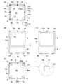
図4(A)は植栽ユニットの平面図であり、図4(B)はこの植栽ユニットの正面図である。図4(C)はこの植栽ユニットの右側面図であり、図4(D)はこの植栽ユニットの底面図である。なお図4において、1種類の基本ユニット4Aについてのみ表す。その他の基本ユニット4B,4C,4Dについては、外形寸法を除き図4の基本ユニット4Aと同一構造であるから詳細図を省略するものとする。なお以下の図において、基本ユニット4A〜4Dを総称して基本ユニット4Aと言う場合がある。
FIG. 4A is a plan view of the planting unit, and FIG. 4B is a front view of the planting unit. FIG.4 (C) is a right view of this planting unit, and FIG.4 (D) is a bottom view of this planting unit. In FIG. 4, only one type of
各基本ユニット4Aは、正面、側面、および上面がそれぞれ矩形孔状に開放された箱状とされる。各基本ユニット4Aは、下部から上部に向かって順次、プランタ設置部8と、複数の柱部9と、水平方向に延びる複数の連結部10とを有する。プランタ設置部8は、各基本ユニット4Aの下部に位置し、有底の矩形箱状に形成される。このプランタ設置部8に、植物2(図1)が植えられた鉢(図示せず)が設置される。具体的には、プランタ設置部8の底部8aにプランタ11が設置され、このプランタ11の上部には矩形板状のトレー12が取り付けられる。このトレー12に、定められた外形および高さ寸法の前記鉢が複数(例えば、4個)着脱自在に設置される。
Each
複数(この例では4本)の柱部9は、矩形箱状のプランタ設置部8における四隅の上縁部から上下方向にそれぞれ延びる。これら柱部9の上下方向の長さは、基本ユニット4Aの高さ寸法H(図1)に応じて定められる。各柱部9は、隣接する面に所定小距離延びる断面略L字形状に形成される。複数の柱部9のうち定められた柱部9におけるコーナー部9aに沿って、後述する流路である給水チューブ13(図10)が設けられている。前記コーナー部9aとは、いずれかの柱部9における断面略L字形状の内側面部を成す部分である。複数の連結部10は、これら複数の柱部9の上端部をそれぞれ矩形枠状に繋ぐ。
A plurality (four in this example) of
ユニット固定手段5について説明する。
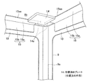
図5(A)は、この緑化ユニット装置におけるユニット固定手段5の要部の断面図(図5(B)のVA-VA線断面図)である。図5(B)はこのユニット固定手段5の要部の正面図である。図4および図5に示すように、ユニット固定手段5は、位置決め手段である位置決めプレート14、上部リブ15、ボルト(図示せず)およびナット16を有する。
The unit fixing means 5 will be described.
FIG. 5A is a cross-sectional view (a cross-sectional view taken along the line VA-VA in FIG. 5B) of the main part of the unit fixing means 5 in this greening unit apparatus. FIG. 5B is a front view of the main part of the unit fixing means 5. As shown in FIGS. 4 and 5, the unit fixing means 5 includes a
図4に示すように、プランタ設置部8の底面8bには、上下に隣接する基本ユニット4Aを互いに位置決めして組み合わせる位置決めプレート14が溶接等により複数箇所(この例では4箇所)設けられる。
図4(D)および図6に示すように、各位置決めプレート14は、矩形板状にそれぞれ形成され、プランタ設置部8の底面8bにおける四隅付近部に固定される。各位置決めプレート14は、上部リブ15の連結部10への取付位置に応じて、プランタ設置部8の底面8bに固定される。換言すれば、位置決めプレート14のプランタ設置部8の底面8bへの固定位置に対応して、上部リブ15が連結部10の内側面に取り付けられている。
As shown in FIG. 4, on the
As shown in FIGS. 4D and 6, each positioning
図4(A)、図5および図6に示すように、各連結部10の内側面には、長手方向両端部を除き上部リブ15が溶接等によりそれぞれ固定される。これら上部リブ15は、この基本ユニット4Aを補強しつつ後述する水平板部15aの上面に、別の基本ユニット4Aを重ねて支持する機能を有する。各上部リブ15は、立板部15bと水平板部15aとで断面L字形状に形成される。立板部15bは、各連結部10の内側面に沿って溶接等により固定される。水平板部15aは、立板部15bの上端縁部から基本ユニット内に水平方向に定められた距離延びる。
As shown in FIGS. 4A, 5, and 6, the
隣り合う水平板部15a,15aにおける先端縁部15aa,15aaに、各位置決めプレート14における外側面部14a,14aがそれぞれ係合するように、上下の基本ユニット4A,4Aが組み合わされて互いに位置決めされる。各位置決めプレート14が水平板部15aの先端縁部15aaにそれぞれ係合された状態で、これら水平板部15aの上面に、上側の基本ユニット4Aにおけるプランタ設置部8の底面8bが支持されるようになっている。
The upper and lower
水平板部15aにおける例えば長手方向中間付近には、前記ボルトを貫通する貫通孔(図示せず)が形成されている。但し、この貫通孔は、水平板部15aの長手方向中間付近に限定して設けられるものではない。前記貫通孔が形成されている位置に対応して、基本ユニット4Aにおけるプランタ設置部8の底面8bに貫通孔8baが形成される。水平板部15aのうち貫通孔がある下面には、前記ナット16が溶接により接合されている。
A through hole (not shown) that penetrates the bolt is formed, for example, near the middle in the longitudinal direction of the
よって、下側の基本ユニット4Aにおける上部リブ15に対し上側の基本ユニット4Aの各位置決めプレート14が位置決めされ、さらに前記上部リブ15に上側の基本ユニット4Aが支持される。この状態で、上側の基本ユニット4Aのプランタ設置部8から下側の基本ユニット4Aの各ナット16にボルトがそれぞれ螺合されることで、上下の基本ユニット4A,4Aが互いに固定される。なお前記と同様のユニット固定手段5により、下側のタンクケース7(図1)と上側の基本ユニット4Aとが互いに組み合わされて固定される。
Therefore, each positioning
図7(A)は、この緑化ユニット装置におけるカバー部材17の正面図であり、図7(B)は同カバー部材17の断面図である。これら図7および図4(A)に示すように、定められた柱部9におけるコーナー部9aには、敷設した給水チューブ13および電源ケーブル(図示せず)を覆うカバー部材17が設けられている。このカバー部材17は、断面円弧状の円弧部17aと、この円弧部17aの周方向一端から同円弧部17aが湾曲する方向に平坦に延びる平坦部17bとを有する。この平坦部17bにおける外側面17baにマグネットテープ(図示せず)が固着される。柱部9のコーナー部9aのうちいずれか一方の内側面部に、平坦部17bの前記マグネットテープを吸着させ、円弧部17aが基本ユニット内に向けて凸となるように設けられる。柱部9のコーナー部9aとカバー部材17の円弧部17aとで囲まれる空間に、前記給水チューブ13および前記電源ケーブルが設けられる。
FIG. 7A is a front view of the
灌水手段6等について説明する。
図8は、この緑化ユニット装置における灌水手段6の構成を示すブロック図である。この灌水手段6は、前述のユニット固定手段5(図4(A))で固定された各基本ユニット4A〜4D(図1)にそれぞれ灌水を行うものである。灌水手段6は、タンクケース7、タンク18、ポンプ19、電磁弁21、および制御手段22を有する灌水ユニットKuと、給水チューブ13と、継手20(図10)とを有する。タンクケース7には、水を貯留するタンク18が収納されている。またタンクケース7内には、ポンプ19、複数の電磁弁21、および制御手段22が搭載されている。タンク18とポンプ19との間およびポンプ19と定められた電磁弁21との間に、給水チューブ13がそれぞれ配管接続されている。各電磁弁21には、複数系列(図8の例では4系列)の給水チューブ13がそれぞれ配管接続されている。
The irrigation means 6 will be described.
FIG. 8 is a block diagram showing the configuration of the irrigation means 6 in this greening unit apparatus. This irrigation means 6 irrigates each of the
ポンプ19は、タンク18に貯留された水を各基本ユニット4A〜4D(図1)に供給する。複数の電磁弁21は、給水チューブ13の系列毎に給水を行うように流路を切替えるものである。複数の電磁弁21として例えば電磁弁マニホールドが適用されている。制御手段22は、これら電磁弁21を制御する手段であって、例えば、プログラマブルコントローラ(略称PLC)により構成される。制御手段22には、複数の電磁弁21の設定および動作を行うための押しボタンスイッチ23が電気的に接続されている。この押しボタンスイッチ23を操作することで、制御手段22は、各基本ユニット4A〜4D(図1)に設置された植物2(図1)に対し、定められた周期で定められた量の灌水を行うことが可能である。
The
図9は、この灌水手段6の配管イメージを示す概略図である。図8および図9に示すように、この灌水手段6は、構成するシステムの縦系列を1系統とし、例えば、最大で6系統まで構成可能である。灌水ユニットKuから遠い(1)系統、(2)系統、(3)系統、(4)系統の順に、縦系列の順序配列で配管が行われる。この場合において、給水チューブ13は、基本ユニット4A〜4Dのいずれかの柱部9(図7(B))におけるコーナー部9a(図7(B))に沿って敷設される。
FIG. 9 is a schematic view showing a piping image of the irrigation means 6. As shown in FIGS. 8 and 9, the irrigation means 6 can be configured up to a maximum of 6 systems, for example, with a vertical system of the system constituting one system. Piping is performed in the order of the vertical series in the order of (1) system, (2) system, (3) system, and (4) system far from the irrigation unit Ku. In this case, the
図10に示すように、継手20は、縦系列において上または下に隣接する基本ユニット4A,4Aに敷設される給水チューブ13同士を繋ぐ。給水チューブ13を継手20に挿し込むことで、基本ユニット4A,4A間の配管を結合させ得る。また図11に示すように、植物への給水用の流路部分13AをT字継手20Aに挿し込むことで、給水部の配管を接続し得る。各基本ユニット4Aに給水チューブ13が設けられ、この給水チューブ13は、前記各基本ユニット4Aに水を導く流路部分13Aと、各基本ユニット4Aに隣接する次段の基本ユニット4Aに水を導く流路部分13Bとを有する。なお図12に示すように、植物が入る基本ユニット4Aのうち、最上段の基本ユニット4Aについては、T字継手20Aの上部にプラグ24を挿入することで、水漏れを防止し得る。
As shown in FIG. 10, the joint 20 connects the
作用効果について説明する。
以上説明した緑化ユニット装置1によれば、複数の基本ユニット4A〜4Dを使用者等の好みに合わせて自由に組替え、ユニット固定手段5は、これら基本ユニット4A〜4Dを組み合わせて固定し得る。灌水手段6は、固定された各基本ユニット4A〜4Dにそれぞれ灌水を行う。このように基本ユニット4A〜4Dを自由に組替えてユニット固定手段5で固定できるため、複数の基本ユニット4A〜4Dを簡易に組み合わせて使用することができる。各基本ユニット4A〜4Dは、それぞれ正面が開放された箱状とされ底部8aに植物2が設置されるため、使用者等は、植物2を直接鑑賞することができるうえ、各基本ユニット4A〜4Dに対して植物2を設置または交換することが容易に行える。このような緑化ユニット装置1をオフィス等の室内に設けることで、室内空間の価値の向上を図ることができる。
The effect will be described.
According to the
灌水手段6は、タンク18に貯留した水をポンプ19で吸い上げて給水チューブ13を介して複数の基本ユニット4A〜4Dにそれぞれ導く。緑化ユニット装置1はこのような灌水手段6を有するため、植物2を管理、世話する管理者の作業負担の低減を図ることができる。
The irrigation means 6 sucks up the water stored in the
各基本ユニット4A〜4Dのいずれかの柱部9におけるコーナー部9aに沿って給水チューブ13を設けたため、緑化ユニット装置1の外観上、給水チューブ13を目立たないように処理して植物2を鑑賞し得る。
灌水手段6は、上または下に隣接する基本ユニット4A,4Aに設けられる給水チューブ13,13同士を繋ぐ継手20,(20A)を有する。このため、様々な基本ユニット4Aの上下の組み合わせに対応することが可能となる。したがって、複数の基本ユニット4A〜4Dの組み合わせのバリエーションを多くして、使用者等の要求に沿う形状の緑化ユニット装置1を容易に実現できる。
Since the
The irrigation means 6 has a joint 20, (20 </ b> A) that connects the
柱部9のコーナー部9aにそって敷設した給水チューブ13をカバー部材17で覆うことで、敷設した給水チューブ13が露出して美観を損ねることを未然に防止することができる。
ユニット固定手段5は、上下に隣接する基本ユニット4A,4Aを互いに位置決めして組み合わせる位置決めプレート14を含む。このため、基本ユニット4A,4Aを上下に組み合わせるとき、位置決めプレート14で互いに位置決めして組み合わせることができ、組立てを簡単化することができる。
By covering the
The unit fixing means 5 includes a
他の実施形態について説明する。
以下の説明においては、各形態で先行する形態で説明している事項に対応している部分には同一の参照符号を付し、重複する説明を略する。構成の一部のみを説明している場合、構成の他の部分は、特に記載のない限り先行して説明している形態と同様とする。同一の構成から同一の作用効果を奏する。実施の各形態で具体的に説明している部分の組合せばかりではなく、特に組合せに支障が生じなければ、実施の形態同士を部分的に組合せることも可能である。
Another embodiment will be described.
In the following description, the same reference numerals are assigned to the portions corresponding to the matters described in the preceding forms in each embodiment, and overlapping descriptions are omitted. When only a part of the configuration is described, the other parts of the configuration are the same as those described in advance unless otherwise specified. The same effect is obtained from the same configuration. Not only the combination of the parts specifically described in each embodiment, but also the embodiments can be partially combined as long as the combination does not hinder.
図13に示すように、灌水手段は、各基本ユニット4Aへの給水量を調整する給水量調整手段25を有するものとしても良い。
各基本ユニット4Aへの給水量が不所望に異なる場合がある。また設置した植物の種類によっては給水量を個別に調整したい場合がある。このような場合に給水量調整手段25により各基本ユニット4Aへの給水量を適宜調整し得る。
As shown in FIG. 13, the irrigation means may include a water supply amount adjusting means 25 that adjusts the water supply amount to each
The amount of water supplied to each
この例では、植物への給水を行う流路部分13AとT字継手20Aとの間の管路途中に給水量調整手段25を介在させている。この給水量調整手段25として、例えば、スロットルバルブが適用される。このスロットルバルブの調整つまみ25aを緩めることで給水量が増加し、調整つまみ25aを締めることで給水量は減少する。給水量の微調整については、上段の基本ユニット4Aから順に調整を行うことで、全ての基本ユニット4A〜4Dの給水量を適量に調整し得る。
In this example, the water supply amount adjusting means 25 is interposed in the middle of the pipe line between the
図14または図15に示すように、複数の基本ユニット4A〜4Dの上下左右の組み合わせ例を変更して使用しても良い。このように複数の基本ユニット4A〜4Dの組み合わせのバリエーションを多くして、使用者等の要求に沿う形状の緑化ユニット装置1を容易に実現できる。なお複数の基本ユニット4A〜4Dの組み合わせ例はこれらの例に限定されるものではない。
As shown in FIG. 14 or FIG. 15, a combination example of a plurality of
以上、実施形態に基づいてこの発明を実施するための形態を説明したが、今回開示された実施の形態はすべての点で例示であって制限的なものではない。この発明の範囲は上記した説明ではなくて特許請求の範囲によって示され、特許請求の範囲と均等の意味および範囲内でのすべての変更が含まれることが意図される。 As mentioned above, although the form for implementing this invention based on embodiment was demonstrated, embodiment disclosed this time is an illustration and restrictive at no points. The scope of the present invention is defined by the terms of the claims, rather than the description above, and is intended to include any modifications within the scope and meaning equivalent to the terms of the claims.
1…緑化ユニット装置
2…植物
4…植栽ユニット
5…ユニット固定手段
6…灌水手段
8…プランタ設置部
9…柱部
13…給水チューブ(流路)
13A,13B…流路部分
14…位置決めプレート(位置決め手段)
17…カバー部材
18…タンク
19…ポンプ
20,20A…継手,T字継手
25…給水量調整手段
Ku…灌水ユニット
DESCRIPTION OF
13A, 13B ... flow
17 ...
Claims (9)
組替え可能な前記複数の植栽ユニットと、
これら植栽ユニットを組み合わせて互いに固定可能なユニット固定手段と、
このユニット固定手段で固定された各植栽ユニットにそれぞれ灌水を行う灌水手段と、
を備え、
前記各植栽ユニットは、それぞれ正面が窓とされた箱状とされ底部に植物が設置されることを特徴とする緑化ユニット装置。 It is a greening unit device that combines a plurality of planting units for installing plants vertically and horizontally,
A plurality of planting units that can be recombined;
Unit fixing means that can be fixed together by combining these planting units;
Irrigation means for irrigating each planting unit fixed by the unit fixing means,
With
Each of the planting units has a box shape whose front is a window, and a plant is installed at the bottom.
有底の箱状に形成され植物が設置されるプランタ設置部と、
このプランタ設置部における上縁部から上下方向に延びる複数の柱部と、
これら柱部の上端部を繋ぐ水平方向に延びる複数の連結部とで正面が窓とされた箱状とされ且つ流路を有し、
この流路は、前記プランタ設置部に設置された植物に水を導く流路部分と、この植栽ユニットに隣接して組み合わせられる植栽ユニットに水を導く流路部分とを有する植栽ユニット。
A planting unit that can be combined in multiple ways,
A planter installation part in which a plant is installed in a box shape with a bottom;
A plurality of pillars extending vertically from the upper edge in the planter installation part;
A plurality of connecting portions extending in the horizontal direction connecting the upper end portions of these pillar portions are box-shaped with a front face as a window and have a flow path,
This flow path is a planting unit having a flow path part for guiding water to a plant installed in the planter installation part and a flow path part for guiding water to a planting unit combined adjacent to the planting unit.
Priority Applications (1)
| Application Number | Priority Date | Filing Date | Title |
|---|---|---|---|
| JP2015129499A JP2017012025A (en) | 2015-06-29 | 2015-06-29 | Greening unit device and planting unit |
Applications Claiming Priority (1)
| Application Number | Priority Date | Filing Date | Title |
|---|---|---|---|
| JP2015129499A JP2017012025A (en) | 2015-06-29 | 2015-06-29 | Greening unit device and planting unit |
Publications (1)
| Publication Number | Publication Date |
|---|---|
| JP2017012025A true JP2017012025A (en) | 2017-01-19 |
Family
ID=57827329
Family Applications (1)
| Application Number | Title | Priority Date | Filing Date |
|---|---|---|---|
| JP2015129499A Pending JP2017012025A (en) | 2015-06-29 | 2015-06-29 | Greening unit device and planting unit |
Country Status (1)
| Country | Link |
|---|---|
| JP (1) | JP2017012025A (en) |
Cited By (1)
| Publication number | Priority date | Publication date | Assignee | Title |
|---|---|---|---|---|
| JP2023096618A (en) * | 2021-12-27 | 2023-07-07 | サンエービルドシステム株式会社 | Irrigation system using T-shaped connector and T-shaped connector |
Citations (7)
| Publication number | Priority date | Publication date | Assignee | Title |
|---|---|---|---|---|
| JPS60127727U (en) * | 1984-02-03 | 1985-08-28 | ニチゾウモデルエンジニアリング株式会社 | Multi-stage cultivation equipment |
| JPS63158155U (en) * | 1987-03-31 | 1988-10-17 | ||
| JPH02299519A (en) * | 1989-05-15 | 1990-12-11 | Kagaku Giken Kk | Unit greenhouse |
| JPH11206534A (en) * | 1998-01-27 | 1999-08-03 | Matsushita Electric Works Ltd | Entrance pole |
| US6178692B1 (en) * | 1994-07-21 | 2001-01-30 | Agri-Grow Technologies, Inc. | Lighting system for use with a vertical growing column |
| JP2013201922A (en) * | 2012-03-27 | 2013-10-07 | Chugoku Electric Power Co Inc:The | Plant cultivation device |
| JP2014011970A (en) * | 2012-07-04 | 2014-01-23 | Daiwa House Industry Co Ltd | Plant cultivation device |
-
2015
- 2015-06-29 JP JP2015129499A patent/JP2017012025A/en active Pending
Patent Citations (7)
| Publication number | Priority date | Publication date | Assignee | Title |
|---|---|---|---|---|
| JPS60127727U (en) * | 1984-02-03 | 1985-08-28 | ニチゾウモデルエンジニアリング株式会社 | Multi-stage cultivation equipment |
| JPS63158155U (en) * | 1987-03-31 | 1988-10-17 | ||
| JPH02299519A (en) * | 1989-05-15 | 1990-12-11 | Kagaku Giken Kk | Unit greenhouse |
| US6178692B1 (en) * | 1994-07-21 | 2001-01-30 | Agri-Grow Technologies, Inc. | Lighting system for use with a vertical growing column |
| JPH11206534A (en) * | 1998-01-27 | 1999-08-03 | Matsushita Electric Works Ltd | Entrance pole |
| JP2013201922A (en) * | 2012-03-27 | 2013-10-07 | Chugoku Electric Power Co Inc:The | Plant cultivation device |
| JP2014011970A (en) * | 2012-07-04 | 2014-01-23 | Daiwa House Industry Co Ltd | Plant cultivation device |
Cited By (2)
| Publication number | Priority date | Publication date | Assignee | Title |
|---|---|---|---|---|
| JP2023096618A (en) * | 2021-12-27 | 2023-07-07 | サンエービルドシステム株式会社 | Irrigation system using T-shaped connector and T-shaped connector |
| JP7454260B2 (en) | 2021-12-27 | 2024-03-22 | サンエービルドシステム株式会社 | T-type connector and irrigation system using T-type connector |
Similar Documents
| Publication | Publication Date | Title |
|---|---|---|
| JP5785555B2 (en) | Container planting system in vertical or inclined arrangement | |
| US12507647B2 (en) | Method for growing agricultural products in closed environments comprising a plurality of air conditioned rooms | |
| TW201143603A (en) | Planting container | |
| AU2013204816B2 (en) | Safety Edge and Irrigation Component | |
| JP5828116B2 (en) | Plant rearing system | |
| WO2009098762A1 (en) | Wall-greening unit provided with irrigation pipe | |
| KR102048147B1 (en) | Folwerpot Modume | |
| JP2017012025A (en) | Greening unit device and planting unit | |
| KR101530433B1 (en) | A flowerpot formed the grating structure | |
| KR20120060096A (en) | flowerpot device | |
| KR20140013583A (en) | Prefab planter | |
| KR101387205B1 (en) | Cultivation apparatus with structure of multiple layers | |
| JP6660177B2 (en) | Parking lot greening system | |
| KR20150146001A (en) | Noise protection equipment container between layers or side | |
| KR20200114719A (en) | Fabricated dual flower pot | |
| JP4535471B2 (en) | Water supply system | |
| KR20220043358A (en) | Lattice type module structure for multistory planting | |
| JP7493477B2 (en) | Greening System | |
| KR102684202B1 (en) | Three-dimensional Planter System with Fine Dust Reduction Function | |
| US10893648B2 (en) | Cultivation floor system for cultivation of plants | |
| JP4796636B2 (en) | Roof greening system | |
| JPH0112593Y2 (en) | ||
| KR200470956Y1 (en) | Assembled type of lamp wall | |
| JP6660237B2 (en) | Greening system using H-section steel | |
| KR20240038501A (en) | A movable stackable cultivation bed |
Legal Events
| Date | Code | Title | Description |
|---|---|---|---|
| A621 | Written request for application examination |
Free format text: JAPANESE INTERMEDIATE CODE: A621 Effective date: 20170303 |
|
| A977 | Report on retrieval |
Free format text: JAPANESE INTERMEDIATE CODE: A971007 Effective date: 20171116 |
|
| A131 | Notification of reasons for refusal |
Free format text: JAPANESE INTERMEDIATE CODE: A131 Effective date: 20171128 |
|
| A521 | Request for written amendment filed |
Free format text: JAPANESE INTERMEDIATE CODE: A523 Effective date: 20180122 |
|
| A02 | Decision of refusal |
Free format text: JAPANESE INTERMEDIATE CODE: A02 Effective date: 20180206 |