JP2017013041A - Electrostatic precipitator - Google Patents

Electrostatic precipitator Download PDF

Info

Publication number
JP2017013041A
JP2017013041A JP2015232405A JP2015232405A JP2017013041A JP 2017013041 A JP2017013041 A JP 2017013041A JP 2015232405 A JP2015232405 A JP 2015232405A JP 2015232405 A JP2015232405 A JP 2015232405A JP 2017013041 A JP2017013041 A JP 2017013041A
Authority
JP
Japan
Prior art keywords
electrode
high voltage
charging unit
counter electrode
voltage electrode
Prior art date
Legal status (The legal status is an assumption and is not a legal conclusion. Google has not performed a legal analysis and makes no representation as to the accuracy of the status listed.)
Pending
Application number
JP2015232405A
Other languages
Japanese (ja)
Inventor
一利 竹之下
Kazutoshi Takenoshita
一利 竹之下
政郎 弓削
Masao Yuge
政郎 弓削
大輔 福岡
Daisuke Fukuoka
大輔 福岡
泰彦 河内山
Yasuhiko Kochiyama
泰彦 河内山
Current Assignee (The listed assignees may be inaccurate. Google has not performed a legal analysis and makes no representation or warranty as to the accuracy of the list.)
Samsung Electronics Co Ltd
Original Assignee
Samsung Electronics Co Ltd
Priority date (The priority date is an assumption and is not a legal conclusion. Google has not performed a legal analysis and makes no representation as to the accuracy of the date listed.)
Filing date
Publication date
Application filed by Samsung Electronics Co Ltd filed Critical Samsung Electronics Co Ltd
Priority to KR1020150180688A priority Critical patent/KR102478243B1/en
Priority to CN201580069946.6A priority patent/CN107107074B/en
Priority to US15/538,881 priority patent/US10766039B2/en
Priority to PCT/KR2015/014012 priority patent/WO2016105045A1/en
Publication of JP2017013041A publication Critical patent/JP2017013041A/en
Pending legal-status Critical Current

Links

Images

Classifications

    • BPERFORMING OPERATIONS; TRANSPORTING
    • B03SEPARATION OF SOLID MATERIALS USING LIQUIDS OR USING PNEUMATIC TABLES OR JIGS; MAGNETIC OR ELECTROSTATIC SEPARATION OF SOLID MATERIALS FROM SOLID MATERIALS OR FLUIDS; SEPARATION BY HIGH-VOLTAGE ELECTRIC FIELDS
    • B03CMAGNETIC OR ELECTROSTATIC SEPARATION OF SOLID MATERIALS FROM SOLID MATERIALS OR FLUIDS; SEPARATION BY HIGH-VOLTAGE ELECTRIC FIELDS
    • B03C3/00Separating dispersed particles from gases or vapour, e.g. air, by electrostatic effect
    • B03C3/02Plant or installations having external electricity supply
    • BPERFORMING OPERATIONS; TRANSPORTING
    • B03SEPARATION OF SOLID MATERIALS USING LIQUIDS OR USING PNEUMATIC TABLES OR JIGS; MAGNETIC OR ELECTROSTATIC SEPARATION OF SOLID MATERIALS FROM SOLID MATERIALS OR FLUIDS; SEPARATION BY HIGH-VOLTAGE ELECTRIC FIELDS
    • B03CMAGNETIC OR ELECTROSTATIC SEPARATION OF SOLID MATERIALS FROM SOLID MATERIALS OR FLUIDS; SEPARATION BY HIGH-VOLTAGE ELECTRIC FIELDS
    • B03C3/00Separating dispersed particles from gases or vapour, e.g. air, by electrostatic effect
    • B03C3/02Plant or installations having external electricity supply
    • B03C3/025Combinations of electrostatic separators, e.g. in parallel or in series, stacked separators or dry-wet separator combinations
    • BPERFORMING OPERATIONS; TRANSPORTING
    • B03SEPARATION OF SOLID MATERIALS USING LIQUIDS OR USING PNEUMATIC TABLES OR JIGS; MAGNETIC OR ELECTROSTATIC SEPARATION OF SOLID MATERIALS FROM SOLID MATERIALS OR FLUIDS; SEPARATION BY HIGH-VOLTAGE ELECTRIC FIELDS
    • B03CMAGNETIC OR ELECTROSTATIC SEPARATION OF SOLID MATERIALS FROM SOLID MATERIALS OR FLUIDS; SEPARATION BY HIGH-VOLTAGE ELECTRIC FIELDS
    • B03C3/00Separating dispersed particles from gases or vapour, e.g. air, by electrostatic effect
    • B03C3/34Constructional details or accessories or operation thereof
    • B03C3/66Applications of electricity supply techniques
    • B03C3/68Control systems therefor
    • AHUMAN NECESSITIES
    • A47FURNITURE; DOMESTIC ARTICLES OR APPLIANCES; COFFEE MILLS; SPICE MILLS; SUCTION CLEANERS IN GENERAL
    • A47LDOMESTIC WASHING OR CLEANING; SUCTION CLEANERS IN GENERAL
    • A47L9/00Details or accessories of suction cleaners, e.g. mechanical means for controlling the suction or for effecting pulsating action; Storing devices specially adapted to suction cleaners or parts thereof; Carrying-vehicles specially adapted for suction cleaners
    • A47L9/10Filters; Dust separators; Dust removal; Automatic exchange of filters
    • A47L9/16Arrangement or disposition of cyclones or other devices with centrifugal action
    • A47L9/1683Dust collecting chambers; Dust collecting receptacles
    • BPERFORMING OPERATIONS; TRANSPORTING
    • B03SEPARATION OF SOLID MATERIALS USING LIQUIDS OR USING PNEUMATIC TABLES OR JIGS; MAGNETIC OR ELECTROSTATIC SEPARATION OF SOLID MATERIALS FROM SOLID MATERIALS OR FLUIDS; SEPARATION BY HIGH-VOLTAGE ELECTRIC FIELDS
    • B03CMAGNETIC OR ELECTROSTATIC SEPARATION OF SOLID MATERIALS FROM SOLID MATERIALS OR FLUIDS; SEPARATION BY HIGH-VOLTAGE ELECTRIC FIELDS
    • B03C3/00Separating dispersed particles from gases or vapour, e.g. air, by electrostatic effect
    • B03C3/02Plant or installations having external electricity supply
    • B03C3/04Plant or installations having external electricity supply dry type
    • B03C3/08Plant or installations having external electricity supply dry type characterised by presence of stationary flat electrodes arranged with their flat surfaces parallel to the gas stream
    • BPERFORMING OPERATIONS; TRANSPORTING
    • B03SEPARATION OF SOLID MATERIALS USING LIQUIDS OR USING PNEUMATIC TABLES OR JIGS; MAGNETIC OR ELECTROSTATIC SEPARATION OF SOLID MATERIALS FROM SOLID MATERIALS OR FLUIDS; SEPARATION BY HIGH-VOLTAGE ELECTRIC FIELDS
    • B03CMAGNETIC OR ELECTROSTATIC SEPARATION OF SOLID MATERIALS FROM SOLID MATERIALS OR FLUIDS; SEPARATION BY HIGH-VOLTAGE ELECTRIC FIELDS
    • B03C3/00Separating dispersed particles from gases or vapour, e.g. air, by electrostatic effect
    • B03C3/02Plant or installations having external electricity supply
    • B03C3/04Plant or installations having external electricity supply dry type
    • B03C3/09Plant or installations having external electricity supply dry type characterised by presence of stationary flat electrodes arranged with their flat surfaces at right angles to the gas stream
    • BPERFORMING OPERATIONS; TRANSPORTING
    • B03SEPARATION OF SOLID MATERIALS USING LIQUIDS OR USING PNEUMATIC TABLES OR JIGS; MAGNETIC OR ELECTROSTATIC SEPARATION OF SOLID MATERIALS FROM SOLID MATERIALS OR FLUIDS; SEPARATION BY HIGH-VOLTAGE ELECTRIC FIELDS
    • B03CMAGNETIC OR ELECTROSTATIC SEPARATION OF SOLID MATERIALS FROM SOLID MATERIALS OR FLUIDS; SEPARATION BY HIGH-VOLTAGE ELECTRIC FIELDS
    • B03C3/00Separating dispersed particles from gases or vapour, e.g. air, by electrostatic effect
    • B03C3/02Plant or installations having external electricity supply
    • B03C3/04Plant or installations having external electricity supply dry type
    • B03C3/12Plant or installations having external electricity supply dry type characterised by separation of ionising and collecting stations
    • BPERFORMING OPERATIONS; TRANSPORTING
    • B03SEPARATION OF SOLID MATERIALS USING LIQUIDS OR USING PNEUMATIC TABLES OR JIGS; MAGNETIC OR ELECTROSTATIC SEPARATION OF SOLID MATERIALS FROM SOLID MATERIALS OR FLUIDS; SEPARATION BY HIGH-VOLTAGE ELECTRIC FIELDS
    • B03CMAGNETIC OR ELECTROSTATIC SEPARATION OF SOLID MATERIALS FROM SOLID MATERIALS OR FLUIDS; SEPARATION BY HIGH-VOLTAGE ELECTRIC FIELDS
    • B03C3/00Separating dispersed particles from gases or vapour, e.g. air, by electrostatic effect
    • B03C3/34Constructional details or accessories or operation thereof
    • B03C3/36Controlling flow of gases or vapour
    • B03C3/368Controlling flow of gases or vapour by other than static mechanical means, e.g. internal ventilator or recycler
    • BPERFORMING OPERATIONS; TRANSPORTING
    • B03SEPARATION OF SOLID MATERIALS USING LIQUIDS OR USING PNEUMATIC TABLES OR JIGS; MAGNETIC OR ELECTROSTATIC SEPARATION OF SOLID MATERIALS FROM SOLID MATERIALS OR FLUIDS; SEPARATION BY HIGH-VOLTAGE ELECTRIC FIELDS
    • B03CMAGNETIC OR ELECTROSTATIC SEPARATION OF SOLID MATERIALS FROM SOLID MATERIALS OR FLUIDS; SEPARATION BY HIGH-VOLTAGE ELECTRIC FIELDS
    • B03C3/00Separating dispersed particles from gases or vapour, e.g. air, by electrostatic effect
    • B03C3/34Constructional details or accessories or operation thereof
    • B03C3/40Electrode constructions
    • B03C3/45Collecting-electrodes
    • B03C3/47Collecting-electrodes flat, e.g. plates, discs, gratings
    • BPERFORMING OPERATIONS; TRANSPORTING
    • B03SEPARATION OF SOLID MATERIALS USING LIQUIDS OR USING PNEUMATIC TABLES OR JIGS; MAGNETIC OR ELECTROSTATIC SEPARATION OF SOLID MATERIALS FROM SOLID MATERIALS OR FLUIDS; SEPARATION BY HIGH-VOLTAGE ELECTRIC FIELDS
    • B03CMAGNETIC OR ELECTROSTATIC SEPARATION OF SOLID MATERIALS FROM SOLID MATERIALS OR FLUIDS; SEPARATION BY HIGH-VOLTAGE ELECTRIC FIELDS
    • B03C2201/00Details of magnetic or electrostatic separation
    • B03C2201/10Ionising electrode with two or more serrated ends or sides
    • BPERFORMING OPERATIONS; TRANSPORTING
    • B03SEPARATION OF SOLID MATERIALS USING LIQUIDS OR USING PNEUMATIC TABLES OR JIGS; MAGNETIC OR ELECTROSTATIC SEPARATION OF SOLID MATERIALS FROM SOLID MATERIALS OR FLUIDS; SEPARATION BY HIGH-VOLTAGE ELECTRIC FIELDS
    • B03CMAGNETIC OR ELECTROSTATIC SEPARATION OF SOLID MATERIALS FROM SOLID MATERIALS OR FLUIDS; SEPARATION BY HIGH-VOLTAGE ELECTRIC FIELDS
    • B03C3/00Separating dispersed particles from gases or vapour, e.g. air, by electrostatic effect
    • B03C3/34Constructional details or accessories or operation thereof
    • B03C3/40Electrode constructions
    • B03C3/41Ionising-electrodes

Landscapes

  • Engineering & Computer Science (AREA)
  • Mechanical Engineering (AREA)
  • Automation & Control Theory (AREA)
  • Electrostatic Separation (AREA)

Abstract

【課題】オゾンの発生を抑制しつつ、帯電部を薄くできる電気集塵機などを提供する。【解決手段】電気集塵機1は、高電圧発生回路40から高電圧が供給される高圧電極11と、高圧電極11に対向して設けられ、高電圧発生回路40から基準電圧が供給される対向電極12と、を有し、高圧電極11と対向電極12との間で放電を発生させて浮遊微粒子を帯電させる帯電部10と、帯電部10の通風方向の下流側に配置され、帯電部10にて帯電させた浮遊微粒子を集める集塵部20と、を備え、帯電部10の対向電極12は、導電性材料で構成された導体部と、導体部の少なくとも高圧電極11に対向する側の表面を覆って、高圧電極11と対向電極12との間の放電電流を制限する、体積抵抗率が1014Ω・cm以上且つ1018Ω・cm以下の抵抗体部とを備えている。【選択図】図1An electrostatic precipitator and the like capable of making a charging portion thin while suppressing generation of ozone are provided. An electrostatic precipitator (1) includes a high voltage electrode (11) to which a high voltage is supplied from a high voltage generation circuit (40), a counter electrode to which the high voltage electrode (11) is provided and a reference voltage is supplied from the high voltage generation circuit (40). 12 is disposed on the downstream side in the ventilation direction of the charging unit 10 to generate a discharge between the high-voltage electrode 11 and the counter electrode 12 to charge the suspended fine particles. A counter electrode 12 of the charging unit 10 and a surface of the conductor unit facing at least the high-voltage electrode 11. And a resistive element having a volume resistivity of 1014 Ω · cm or more and 1018 Ω · cm or less that limits the discharge current between the high-voltage electrode 11 and the counter electrode 12. [Selection] Figure 1

Description

本発明は、電気集塵機に関する。   The present invention relates to an electric dust collector.

空気清浄機やエアコンなどの電気製品などには、放電を用いて浮遊微粒子を帯電させる電気集塵機が備えられている。
このような電気集塵機は、放電により浮遊微粒子を帯電させる帯電部と、帯電させた浮遊微粒子を集塵する集塵部とを備えている。電気集塵機の帯電部においては、高圧(放電)電極と対向(接地)電極との間に放電発生のために数kVの高電圧が印加される。
高い集塵効率を得るため、高圧電極と対向電極との間を流れる放電電流を大きくすると、放電に伴ってオゾン(O)が発生しやすくなる。オゾンは独特の臭気を持つため、室内に放出する場合、オゾン濃度は環境基準値(0.05ppm)以下とする必要がある。
Electric appliances such as air purifiers and air conditioners are equipped with electric dust collectors that charge floating particulates by using electric discharge.
Such an electrostatic precipitator includes a charging unit that charges floating particles by electric discharge and a dust collecting unit that collects charged floating particles. In the charging part of the electrostatic precipitator, a high voltage of several kV is applied between the high voltage (discharge) electrode and the counter (ground) electrode to generate a discharge.
If the discharge current flowing between the high-voltage electrode and the counter electrode is increased in order to obtain high dust collection efficiency, ozone (O 3 ) is likely to be generated along with the discharge. Since ozone has a unique odor, the ozone concentration needs to be not more than the environmental standard value (0.05 ppm) when released indoors.

特許文献1には、コロナ放電をさせずにイオンを放出するイオン放出手段とその下流側に設置された集塵部で構成される集塵装置であって、イオン放出手段の放電電極を1もしくは複数個の線状電極とし、線状電極の両側にアース電極を設け、線状電極に高電圧を印加した時の放電電流が線状電極0.1m当たり1μA以下となるようにアースに接続された電極を絶縁体または半導体で被覆することが記載されている。   Patent Document 1 discloses a dust collecting apparatus including an ion emitting unit that emits ions without causing corona discharge and a dust collecting unit installed on the downstream side of the ion collecting unit. A plurality of linear electrodes are provided, and ground electrodes are provided on both sides of the linear electrodes, and are connected to the ground so that the discharge current when a high voltage is applied to the linear electrodes is 1 μA or less per 0.1 m of the linear electrodes. Coating an electrode with an insulator or semiconductor.

特許文献2には、高電圧が印加されるように設けられた放電針を有し中央が前方に膨出した形状の吸気グリルと、放電針の風下側に設けられる通風可能なアース電極と集塵フィルタとを設けたフィルタユニットを備え、吸気グリルを非導電性樹脂からなる非導電リブと、導電性からなる導電リブを格子状に配設して形成し、導電リブをアース電極に接続することにより、吸気グリルに帯電する静電気が逃げて、吸気グリルへの粉塵の付着を防止する電気集塵ユニットが記載されている。   In Patent Document 2, an intake grille having a discharge needle provided so that a high voltage is applied and having a center bulging forward, an air-permeable ground electrode provided on the leeward side of the discharge needle, and a collector A filter unit provided with a dust filter is provided, and the intake grill is formed by disposing a non-conductive rib made of non-conductive resin and a conductive rib made of conductive in a lattice shape, and the conductive rib is connected to the ground electrode. Thus, there is described an electrostatic dust collection unit that prevents static electricity charged in the intake grill from escaping and prevents dust from adhering to the intake grill.

特許文献3には、複数の放電部材と、該放電部材にそれぞれ接続された抵抗体と、該抵抗体に接続された電圧源とを有するコロナ放電装置が記載されている。   Patent Document 3 describes a corona discharge device having a plurality of discharge members, resistors connected to the discharge members, and a voltage source connected to the resistors.

特許文献4には、高電圧を発生する高電圧発生手段と、前記高電圧発生手段の出力に接続されイオンを発生するイオン発生電極とを有するイオン発生器において、前記高電圧発生手段の出力に前記イオン発生電極と並列に接続されたオゾンを発生するオゾン発生電極と、前記オゾン発生電極と直列に接続されたインピーダンス可変手段とを有し、前記インピーダンス可変手段のインピーダンスを変化させることにより前記オゾン発生電極から発生するオゾン量を制御するイオン発生器が記載されている。   In Patent Document 4, an ion generator having a high voltage generating means for generating a high voltage and an ion generating electrode connected to the output of the high voltage generating means for generating ions is used as an output of the high voltage generating means. An ozone generating electrode for generating ozone connected in parallel with the ion generating electrode; and an impedance variable means connected in series with the ozone generating electrode, and changing the impedance of the impedance variable means to change the ozone An ion generator that controls the amount of ozone generated from the generating electrode is described.

非特許文献1には、誘電体の代わりに、電極の一方を数MΩ/cmの高抵抗シートで覆った放電が記載されている。そして、直流(DC)で駆動すると、数μsの幅で数10kHzで繰り返すパルス状の放電が発生することが記載されている。   Non-Patent Document 1 describes a discharge in which one of electrodes is covered with a high resistance sheet of several MΩ / cm instead of a dielectric. It is described that, when driven by direct current (DC), a pulsed discharge that repeats at several tens of kHz with a width of several μs is generated.

国際公開WO01/064349号International Publication No. WO01 / 064349 特開2005−021817号公報JP 2005-021817 A 特開平7−5746号公報Japanese Patent Laid-Open No. 7-5746 特開2004−216037号公報Japanese Patent Laid-Open No. 2004-216037

モーニア・ラロッシー(Mounir Laroussi)、イゴール・アレクセフ(Igor Alexeff)、ポール・リチャードソン(Paul Richardson)、フランシス・エフ・ダイヤー(Francis F. Dyer)、「抵抗バリア放電(The Resistive Barrier Discharge)」、アイトリプルイー・プラズマサイエンストランザクション(IEEE TRANSACTION ON PLASMA SCIENCE)、2002年2月、第30巻、第1号、p.158−159Mounir Laroussi, Igor Alexeff, Paul Richardson, Francis F. Dyer, "The Resistive Barrier Discharge", I IEEE TRANSACTION ON PLASMA SCIENCE, February 2002, Volume 30, Issue 1, p. 158-159

ところで、様々な電気製品に組み込みやすくするため、電気集塵機の小型化が求められている。所望の集塵性能を確保するためには、集塵部は薄くしづらい。よって、帯電部を薄くすることが求められている。
帯電部を薄くすると、高圧電極と対向電極との距離が近づくため、オゾンの発生が増えるおそれがある。
また、0.1μm以下のPM0.1などの超微粒子は、帯電させること自体が難しい上に、質量が小さいため、効率よく捕集できないおそれがある。
本発明の目的は、オゾンの発生を抑制しつつ、帯電部を薄くできる電気集塵機などを提供する。
また、本発明の目的は、オゾンの発生を抑制しつつ、超微粒子が効率よく捕集できる電気集塵機を提供する。
By the way, in order to make it easy to incorporate into various electric products, downsizing of the electric dust collector is required. In order to ensure the desired dust collection performance, the dust collection part is difficult to thin. Therefore, it is required to make the charging part thin.
If the charging portion is made thin, the distance between the high-voltage electrode and the counter electrode approaches, so there is a risk that the generation of ozone will increase.
In addition, ultrafine particles such as PM0.1 of 0.1 μm or less are difficult to be charged and may not be efficiently collected because of their small mass.
An object of the present invention is to provide an electrostatic precipitator that can reduce the charging portion while suppressing generation of ozone.
Moreover, the objective of this invention provides the electrostatic precipitator which can collect an ultrafine particle efficiently, suppressing generation | occurrence | production of ozone.

かかる目的のもと、本発明が適用される電気集塵機は、帯電部と集塵部とを備える。帯電部は、高電圧発生回路から高電圧が供給され、少なくとも電界集中を発生させる部位を有する高圧電極と、当該高圧電極に対向して設けられ、当該高電圧発生回路から基準電圧が供給される対向電極と、を有し、当該高圧電極と当該対向電極との間で放電を発生させて浮遊微粒子を帯電させる。集塵部は、前記帯電部の通風方向の下流側に配置され、当該帯電部にて帯電させた前記浮遊微粒子を集める。   For this purpose, an electric dust collector to which the present invention is applied includes a charging unit and a dust collecting unit. The charging unit is provided with a high voltage from a high voltage generation circuit and is provided opposite to the high voltage electrode having at least a portion that generates electric field concentration, and a reference voltage is supplied from the high voltage generation circuit. A counter electrode, and a discharge is generated between the high-voltage electrode and the counter electrode to charge the suspended fine particles. The dust collection unit is disposed downstream of the charging unit in the ventilation direction, and collects the suspended fine particles charged by the charging unit.

また、かかる目的のもと、本発明が適用される電気集塵機は、帯電部と集塵部とを備える。帯電部は、高電圧発生回路から高電圧が供給される高圧電極を備える。また、当該高圧電極に対向して設けられ、当該高電圧発生回路から基準電圧が供給される対向電極を備える。そして、当該高圧電極と当該対向電極との間で放電を発生させて浮遊微粒子を帯電させる。集塵部は、前記帯電部の通風方向の下流側に配置され、当該帯電部にて帯電させた前記浮遊微粒子を集める。当該帯電部における前記対向電極は、導電性材料で構成された導体部を備える。さらに、前記対向電極は、当該導体部の少なくとも前記高圧電極に対向する側の表面を覆って、当該高圧電極と当該対向電極との間の放電電流を制限する、体積抵抗率が1014Ω・cm以上且つ1018Ω・cm以下の抵抗体部を備える。
このような電気集塵機において、前記帯電部における前記対向電極の前記抵抗体部は、比誘電率が3以上であることを特徴とすることができる。
For this purpose, the electric dust collector to which the present invention is applied includes a charging unit and a dust collecting unit. The charging unit includes a high voltage electrode to which a high voltage is supplied from a high voltage generation circuit. In addition, a counter electrode is provided so as to face the high voltage electrode and to which a reference voltage is supplied from the high voltage generation circuit. Then, a discharge is generated between the high-voltage electrode and the counter electrode to charge the suspended fine particles. The dust collection unit is disposed downstream of the charging unit in the ventilation direction, and collects the suspended fine particles charged by the charging unit. The counter electrode in the charging portion includes a conductor portion made of a conductive material. Further, the counter electrode covers at least a surface of the conductor portion facing the high voltage electrode, and limits a discharge current between the high voltage electrode and the counter electrode, and has a volume resistivity of 10 14 Ω · A resistor portion of not less than cm and not more than 10 18 Ω · cm is provided.
In such an electrostatic precipitator, the resistor portion of the counter electrode in the charging portion may have a relative dielectric constant of 3 or more.

このような電気集塵機において、前記帯電部における前記高圧電極は、ワイヤ形状であることを特徴とすることができる。   In such an electrostatic precipitator, the high-voltage electrode in the charging unit may have a wire shape.

また、前記帯電部における前記高圧電極は、先端が尖った鋸歯形状の部分又は先端が尖った針形状の部分を備えることを特徴とすることができる。
そしてまた、複数の前記鋸歯形状の部分又は複数の前記針形状の部分が、前記通風方向に対して交差するとともに、複数の列に分けられている。そして、当該複数の列のそれぞれにおける当該鋸歯形状の部分の先端又は当該針形状の部分の先端が、隣接する列の間で列方向に互いにずれて配置されている。さらに、当該鋸歯形状の部分又は当該針形状の部分の長さLに対して、当該複数の列間における当該鋸歯形状の部分又は当該針形状の部分の先端間の距離Sが、3L以下である。さらにまた、当該複数の列のそれぞれにおける当該鋸歯形状の部分又は当該針形状の部分の間隔Pが、2L以上であることを特徴とすることができる。
The high-voltage electrode in the charging unit may include a sawtooth-shaped part with a sharp tip or a needle-shaped part with a sharp tip.
In addition, the plurality of sawtooth-shaped portions or the plurality of needle-shaped portions intersect with the ventilation direction and are divided into a plurality of rows. The tips of the saw-toothed portions or the tips of the needle-shaped portions in each of the plurality of rows are arranged so as to be shifted from each other in the row direction between adjacent rows. Further, with respect to the length L of the sawtooth portion or the needle shape portion, the distance S between the tips of the sawtooth portion or the needle shape portion between the plurality of rows is 3L or less. . Furthermore, the interval P between the sawtooth-shaped portion or the needle-shaped portion in each of the plurality of rows may be 2L or more.

これにより、鋸歯形状又は針形状の部分が通風方向に平行に配置された場合に比べ、また高圧電極と対向電極とが通風方向に対して垂直な方向に配置された場合に比べ、帯電部をより薄く構成できる。   As a result, compared with the case where the sawtooth or needle-shaped portion is arranged in parallel to the ventilation direction, and the charging portion is compared to the case where the high voltage electrode and the counter electrode are arranged in a direction perpendicular to the ventilation direction. It can be made thinner.

また、複数の前記鋸歯形状の部分又は複数の前記針形状の部分が、前記通風方向に対して交差するとともに、複数の列に分けられている。そして、当該複数の列のそれぞれにおける当該鋸歯形状の部分の先端又は当該針形状の部分の先端が、隣接する列の間において対向するように配置されている。さらに、当該鋸歯形状の部分又は当該針形状の部分の長さLに対して、当該複数の列間における当該鋸歯形状の部分又は当該針形状の部分の先端の距離Sが、6L以上且つ8L以下である。さらにまた、当該複数の列のそれぞれにおける当該鋸歯形状の部分又は当該針形状の部分の間隔Pが、2L以上であることを特徴とすることができる。   The plurality of sawtooth-shaped portions or the plurality of needle-shaped portions intersect with the ventilation direction and are divided into a plurality of rows. And the tip of the sawtooth portion or the tip of the needle-shaped portion in each of the plurality of rows is arranged so as to face each other between adjacent rows. Furthermore, with respect to the length L of the sawtooth-shaped part or the needle-shaped part, the distance S of the tip of the sawtooth-shaped part or the needle-shaped part between the plurality of rows is 6L or more and 8L or less. It is. Furthermore, the interval P between the sawtooth-shaped portion or the needle-shaped portion in each of the plurality of rows may be 2L or more.

これにより、鋸歯形状又は針形状の部分が通風方向に平行に配置された場合に比べ、また高圧電極と対向電極とが通風方向に対して垂直な方向に配置された場合に比べ、帯電部をより薄く構成できる。   As a result, compared with the case where the sawtooth or needle-shaped portion is arranged in parallel to the ventilation direction, and the charging portion is compared to the case where the high voltage electrode and the counter electrode are arranged in a direction perpendicular to the ventilation direction. It can be made thinner.

さらに、前記帯電部における前記高圧電極は、刷毛形状であることを特徴とすることができる。   Further, the high-voltage electrode in the charging unit may be a brush shape.

また、前記帯電部の前記高圧電極は、主高圧電極と従高圧電極とを備えることを特徴とすることができる。
そして、前記高圧電極において、前記主高圧電極が鋸歯形状の部分又は針形状の部分を備え、前記従高圧電極がワイヤ形状であることを特徴とすることができる。
そしてまた、前記主高圧電極における鋸歯形状の部分又は針形状の部分の先端が前記通風方向の上流側に向いていることを特徴とすることができる。
さらに、前記主高圧電極と前記対向電極との間に、前記従高圧電極が設けられていることを特徴とすることができる。
The high voltage electrode of the charging unit may include a main high voltage electrode and a sub high voltage electrode.
In the high voltage electrode, the main high voltage electrode may have a sawtooth portion or a needle shape portion, and the sub high voltage electrode may have a wire shape.
In addition, the tip of the sawtooth portion or the needle shape portion of the main high-voltage electrode may be directed to the upstream side in the ventilation direction.
Furthermore, the sub high voltage electrode may be provided between the main high voltage electrode and the counter electrode.

また、前記主高圧電極の電圧は、前記従高圧電極の電圧の2倍以上且つ5倍以下に設定されることを特徴とすることができる。
そして、前記主高圧電極は予め定められた電圧に設定され、前記従高圧電極は電圧が設定されない浮遊状態であることを特徴とすることができる。
In addition, the voltage of the main high voltage electrode may be set to be not less than 2 times and not more than 5 times the voltage of the sub high voltage electrode.
The main high voltage electrode may be set to a predetermined voltage, and the sub high voltage electrode may be in a floating state in which no voltage is set.

また、前記帯電部における前記対向電極の前記導体部は、通風を確保するために間隔を置いて配置された複数の平板で構成されていることを特徴とすることができる。
そして、前記帯電部における前記対向電極の前記導体部は、通風を確保するための開口を有する網で構成されていることを特徴とすることができる。
そしてまた、前記帯電部における前記対向電極の前記導体部は、通風を確保するための開口を有するパンチングメタルで構成されていることを特徴とすることができる。
さらに、前記帯電部における前記対向電極の前記導体部は、通風を確保するための開口を有するエキスパンドメタルで構成されていることを特徴とすることができる。
Further, the conductor portion of the counter electrode in the charging portion may be configured by a plurality of flat plates arranged at intervals to ensure ventilation.
And the said conductor part of the said counter electrode in the said charging part is comprised by the net | network which has an opening for ensuring ventilation.
In addition, the conductor portion of the counter electrode in the charging portion may be formed of a punching metal having an opening for ensuring ventilation.
Furthermore, the conductor part of the counter electrode in the charging part may be made of an expanded metal having an opening for ensuring ventilation.

また、前記帯電部における前記対向電極は、当該帯電部の前記高圧電極に対して、前記通風方向の上流側に配置されていることを特徴とすることができる。   Further, the counter electrode in the charging unit may be arranged on the upstream side in the ventilation direction with respect to the high-voltage electrode of the charging unit.

また、かかる目的のもと、本発明が適用される電気集塵機は、帯電部と集塵部とを備える。帯電部は、高電圧発生回路から高電圧が供給される高圧電極を備える。また、当該高圧電極に対向して設けられ、当該高電圧発生回路から基準電圧が供給される対向電極を備える。集塵部は、前記帯電部の通風方向の下流側に配置される。そして、当該集塵部は、他の高電圧発生回路から高電圧が供給される他の高圧電極を備える。また、当該他の高圧電極に対向して設けられ、当該他の高電圧発生回路から基準電圧が供給される他の対向電極を備える。そして、当該集塵部は、当該帯電部にて帯電させた前記浮遊微粒子を集める。さらに、前記帯電部を構成する部材の内、最も前記集塵部に近い部材の端部から通風方向下流に5mm以上の離間距離を持って当該集塵部の前記他の高圧電極が配置されている。   For this purpose, the electric dust collector to which the present invention is applied includes a charging unit and a dust collecting unit. The charging unit includes a high voltage electrode to which a high voltage is supplied from a high voltage generation circuit. In addition, a counter electrode is provided so as to face the high voltage electrode and to which a reference voltage is supplied from the high voltage generation circuit. The dust collection unit is disposed downstream of the charging unit in the ventilation direction. And the said dust collection part is provided with the other high voltage electrode to which a high voltage is supplied from another high voltage generation circuit. In addition, another counter electrode is provided opposite to the other high voltage electrode and supplied with a reference voltage from the other high voltage generation circuit. The dust collection unit collects the suspended fine particles charged by the charging unit. Furthermore, the other high-voltage electrode of the dust collecting part is arranged with a separation distance of 5 mm or more downstream from the end of the member constituting the charging part closest to the dust collecting part in the ventilation direction. Yes.

また、かかる目的のもと、本発明が適用される電気集塵機は、帯電部と集塵部とを備える。帯電部は、高電圧発生回路から高電圧が供給される高圧電極を備える。また、当該高圧電極に対向して設けられ、当該高電圧発生回路から基準電圧が供給される対向電極を備える。そして、当該高圧電極と当該対向電極との間で放電を発生させて浮遊微粒子を帯電させる。集塵部は、前記帯電部の通風方向の下流側に配置され、当該帯電部にて帯電させた前記浮遊微粒子を集める。さらに、樹脂材料で構成され、前記帯電部を収納する筐体を備える。そして、前記帯電部における前記高圧電極は、前記筐体から5mm以上離れて設けられている。   For this purpose, the electric dust collector to which the present invention is applied includes a charging unit and a dust collecting unit. The charging unit includes a high voltage electrode to which a high voltage is supplied from a high voltage generation circuit. In addition, a counter electrode is provided so as to face the high voltage electrode and to which a reference voltage is supplied from the high voltage generation circuit. Then, a discharge is generated between the high-voltage electrode and the counter electrode to charge the suspended fine particles. The dust collection unit is disposed downstream of the charging unit in the ventilation direction, and collects the suspended fine particles charged by the charging unit. Furthermore, the housing | casing comprised with the resin material and accommodates the said charging part is provided. And the said high voltage | pressure electrode in the said charging part is provided 5 mm or more away from the said housing | casing.

このような電気集塵機において、前記帯電部における前記対向電極は、導電性材料で構成された導体部と、当該導体部の少なくとも前記高圧電極に対向する側の表面を覆う抵抗体部と、を備える。そして、前記帯電部を収納する前記筐体は、当該帯電部の前記対向電極の前記導体部に対して、導通する電気的接触を有することを特徴とすることができる。   In such an electrostatic precipitator, the counter electrode in the charging unit includes a conductor part made of a conductive material and a resistor part that covers at least a surface of the conductor part facing the high-voltage electrode. . And the said housing | casing which accommodates the said charging part has the electrical contact which conduct | electrically_connects with respect to the said conductor part of the said counter electrode of the said charging part.

これにより、対向電極が露出領域において筐体と接続されていない場合に比べ、筐体の静電気による帯電がより抑制できる。   Thereby, compared with the case where the counter electrode is not connected to the casing in the exposed region, charging of the casing due to static electricity can be further suppressed.

さらに、かかる目的のもと、本発明が適用される電気集塵機は、帯電部と集塵部とを備える。帯電部は、高電圧発生回路から高電圧が供給される高圧電極を備える。また、当該高圧電極に対向して設けられ、当該高電圧発生回路から基準電圧が供給される対向電極を備える。さらに、インダクタを含み、当該高圧電極と当該対向電極との間に発生する放電におけるパルス状電流によって、当該高圧電極の電位を低下させる電流制限回路を備える。そして、当該高圧電極と当該対向電極との間で放電を発生させて浮遊微粒子を帯電させる。集塵部は、前記帯電部の通風方向の下流側に配置され、当該帯電部にて帯電させた前記浮遊微粒子を集める。   Furthermore, for this purpose, the electric dust collector to which the present invention is applied includes a charging unit and a dust collecting unit. The charging unit includes a high voltage electrode to which a high voltage is supplied from a high voltage generation circuit. In addition, a counter electrode is provided so as to face the high voltage electrode and to which a reference voltage is supplied from the high voltage generation circuit. Furthermore, an inductor is included, and a current limiting circuit is provided that lowers the potential of the high-voltage electrode by a pulsed current in a discharge generated between the high-voltage electrode and the counter electrode. Then, a discharge is generated between the high-voltage electrode and the counter electrode to charge the suspended fine particles. The dust collection unit is disposed downstream of the charging unit in the ventilation direction, and collects the suspended fine particles charged by the charging unit.

これにより、電流制限回路を備えない場合に比べ、二次電子放出にともなうパルス状電流によるオゾン発生の増加がより抑制できる。   Thereby, compared with the case where a current limiting circuit is not provided, an increase in ozone generation due to a pulsed current accompanying secondary electron emission can be further suppressed.

このような電気集塵機において、前記帯電部における前記電流制限回路は、前記インダクタとダイオードとの並列回路で構成されることを特徴とすることができる。
そして、前記帯電部における前記電流制限回路の前記ダイオードは、前記高電圧に対し逆方向に接続されることを特徴とすることができる。
In such an electric dust collector, the current limiting circuit in the charging unit may be configured by a parallel circuit of the inductor and a diode.
The diode of the current limiting circuit in the charging unit may be connected in a reverse direction with respect to the high voltage.

また、前記帯電部における前記電流制限回路は、ジャンクションFETと当該ジャンクションFETのソース−ゲート間に接続された抵抗素子とを有する回路をさらに備えることを特徴とすることができる。ジャンクションFETと当該ジャンクションFETのソース−ゲート間に接続された抵抗素子とを有する回路は、前記インダクタと前記ダイオードとの前記並列回路に直列接続される。   The current limiting circuit in the charging unit may further include a circuit having a junction FET and a resistance element connected between a source and a gate of the junction FET. A circuit having a junction FET and a resistance element connected between the source and gate of the junction FET is connected in series to the parallel circuit of the inductor and the diode.

これにより、ジャンクションFETと抵抗素子とを有する回路を備えない場合に比べ、高圧電極と対向電極と間の短絡電流を抑制できる。   Thereby, compared with the case where the circuit which has junction FET and a resistive element is not provided, the short circuit current between a high voltage electrode and a counter electrode can be suppressed.

そして、前記帯電部における前記電流制限回路は、前記インダクタと前記ダイオードとの前記並列回路に直列接続される、MOSFETと抵抗素子との直列回路をさらに備えることを特徴とすることができる。   The current limiting circuit in the charging unit may further include a series circuit of a MOSFET and a resistance element connected in series to the parallel circuit of the inductor and the diode.

これにより、MOSFETと抵抗素子とを用いた直列回路を備えない場合に比べ、高圧電極と対向電極と間の短絡電流を抑制できる。   Thereby, compared with the case where the series circuit using MOSFET and a resistive element is not provided, the short circuit current between a high voltage electrode and a counter electrode can be suppressed.

さらに、前記帯電部における前記電流制限回路は、前記高電圧発生回路から前記高圧電極への経路上に設けられていることを特徴とすることができる。
さらにまた、前記帯電部における前記高圧電極は、複数の副高圧電極から構成され、前記帯電部における前記電流制限回路は、前記複数の副高圧電極のそれぞれに対して設けられていることを特徴とすることができる。
そして、前記帯電部における前記高圧電極の前記複数の副高圧電極のそれぞれは、複数の鋸歯形状の部分を備え、前記帯電部における前記電流制限回路は、前記鋸歯形状の部分のそれぞれに対して設けられていることを特徴とすることができる。
Furthermore, the current limiting circuit in the charging unit may be provided on a path from the high voltage generation circuit to the high voltage electrode.
Furthermore, the high-voltage electrode in the charging unit includes a plurality of sub-high-voltage electrodes, and the current limiting circuit in the charging unit is provided for each of the plurality of sub-high-voltage electrodes. can do.
Each of the plurality of sub-high voltage electrodes of the high-voltage electrode in the charging unit includes a plurality of sawtooth-shaped portions, and the current limiting circuit in the charging unit is provided for each of the sawtooth-shaped portions. It can be characterized by being.

これにより、複数の副高圧電極のそれぞれに対して電流制限回路を設けない場合に比べ、集塵効率の低下が抑制できる。   Thereby, the fall of dust collection efficiency can be suppressed compared with the case where a current limiting circuit is not provided with respect to each of a plurality of sub high voltage electrodes.

また、このような電気集塵機において、前記帯電部における前記電流制限回路は、前記高電圧発生回路から前記対向電極への経路上に設けられていることを特徴とすることができる。
そして、前記帯電部における前記対向電極は、複数の副対向電極から構成され、前記電流制限回路は、前記複数の副対向電極のそれぞれに対して設けられていることを特徴とすることができる。
In such an electric dust collector, the current limiting circuit in the charging unit may be provided on a path from the high voltage generation circuit to the counter electrode.
The counter electrode in the charging unit may include a plurality of sub counter electrodes, and the current limiting circuit may be provided for each of the plurality of sub counter electrodes.

さらにまた、かかる目的のもと、本発明が適用される電気集塵機は、帯電部と集塵部とを備える。帯電部は、高電圧発生回路から高電圧が供給される高圧電極を備える。また、当該高圧電極に対向して設けられ、当該高電圧発生回路から基準電圧が供給される対向電極を備える。そして、当該高圧電極と当該対向電極との間で放電を発生させて浮遊微粒子を帯電させる。集塵部は、前記帯電部の通風方向の下流側に配置され、当該帯電部にて帯電させた前記浮遊微粒子を集める。当該帯電部における前記対向電極は、導電性材料で構成された導体部と、当該導体部の対向電極側を覆う第1の部材と、当該第1の部材の対向電極側を覆う第2の部材と、を有する。さらに、前記対向電極は、前記第2の部材が前記導体部と、電気的に接触する接触領域を有する。   Furthermore, for this purpose, an electric dust collector to which the present invention is applied includes a charging unit and a dust collecting unit. The charging unit includes a high voltage electrode to which a high voltage is supplied from a high voltage generation circuit. In addition, a counter electrode is provided so as to face the high voltage electrode and to which a reference voltage is supplied from the high voltage generation circuit. Then, a discharge is generated between the high-voltage electrode and the counter electrode to charge the suspended fine particles. The dust collection unit is disposed downstream of the charging unit in the ventilation direction, and collects the suspended fine particles charged by the charging unit. The counter electrode in the charging unit includes a conductor part made of a conductive material, a first member covering the counter electrode side of the conductor part, and a second member covering the counter electrode side of the first member. And having. Furthermore, the counter electrode has a contact region where the second member is in electrical contact with the conductor portion.

このような電気集塵機において、前記帯電部の前記高圧電極は、主高圧電極と従高圧電極とを備えることを特徴とすることができる。
また、前記高圧電極において、前記主高圧電極が鋸歯形状の部分又は針形状の部分を備え、前記従高圧電極がワイヤ形状であることを特徴とすることができる。
そして、前記主高圧電極における前記鋸歯形状の部分又は前記針形状の部分の先端が前記通風方向の上流側に向いていることを特徴とする。
そしてまた、前記高圧電極における前記主高圧電極と前記対向電極との間に、前記従高圧電極が設けられていることを特徴とすることができる。
さらに、前記主高圧電極の電圧は、前記従高圧電極の電圧の2倍以上且つ5倍以下であることを特徴とすることができる。
さらにまた、前記主高圧電極は予め定められた電圧に設定され、前記従高圧電極は電圧が設定されない浮遊状態であることを特徴とすることができる。
In such an electric dust collector, the high voltage electrode of the charging unit may include a main high voltage electrode and a sub high voltage electrode.
Further, the high voltage electrode may be characterized in that the main high voltage electrode has a sawtooth portion or a needle shape portion, and the sub high voltage electrode has a wire shape.
The tip of the saw-toothed portion or the needle-shaped portion of the main high-voltage electrode faces the upstream side in the ventilation direction.
Further, the secondary high voltage electrode may be provided between the main high voltage electrode and the counter electrode in the high voltage electrode.
Further, the voltage of the main high voltage electrode may be not less than 2 times and not more than 5 times the voltage of the sub high voltage electrode.
Furthermore, the main high voltage electrode may be set to a predetermined voltage, and the sub high voltage electrode may be in a floating state in which no voltage is set.

このような電気集塵機において、前記帯電部における前記対向電極の前記第2の部材は、前記第1の部材に比べ、体積抵抗率が小さいことを特徴とすることができる。
また、前記帯電部における前記対向電極の前記第2の部材は、前記高圧電極と前記対向電極との間に5kVを印加したときに、表面抵抗率が1GΩ/cm以上であることを特徴とすることができる。
そして、前記帯電部における前記対向電極の前記導体部は、通風を確保するために間隔を置いて配置された複数の平板で構成されていることを特徴とすることができる。
そしてまた、前記帯電部における前記対向電極の前記導体部は、通風を確保するための開口を有する網で構成されていることを特徴とすることができる。
さらに、前記帯電部における前記対向電極の前記導体部は、通風を確保するための開口を有するパンチングメタルで構成されていることを特徴とすることができる。
さらにまた、前記帯電部における前記対向電極の前記導体部は、通風を確保するための開口を有する導電性材料で構成されたエキスパンドメタルで構成されていることを特徴とすることができる。
In such an electrostatic precipitator, the second member of the counter electrode in the charging unit may have a smaller volume resistivity than the first member.
The second member of the counter electrode in the charging unit has a surface resistivity of 1 GΩ / cm or more when 5 kV is applied between the high-voltage electrode and the counter electrode. be able to.
And the said conductor part of the said counter electrode in the said charging part is comprised by the some flat plate arrange | positioned at intervals in order to ensure ventilation.
In addition, the conductor portion of the counter electrode in the charging portion may be configured by a net having an opening for ensuring ventilation.
Furthermore, the conductor part of the counter electrode in the charging part may be made of a punching metal having an opening for ensuring ventilation.
Furthermore, the conductor part of the counter electrode in the charging part may be made of an expanded metal made of a conductive material having an opening for ensuring ventilation.

これにより、第1の部材を備えない場合に比べ、高圧電極と対向電極との間の破壊電圧をより高くできる。   Thereby, compared with the case where the 1st member is not provided, the breakdown voltage between a high voltage electrode and a counter electrode can be made higher.

また、かかる目的のもと、本発明が適用される電気集塵機は、帯電部と集塵部とを備える。帯電部は、高電圧発生回路から高電圧が供給される高圧電極と、当該高圧電極に対向して設けられ、当該高電圧発生回路から基準電圧が供給される対向電極と、を有している。帯電部は、当該高圧電極と当該対向電極との間で放電を発生させて浮遊微粒子を帯電させる。集塵部は、前記帯電部の通風方向の下流側に配置され、当該帯電部にて帯電させた前記浮遊微粒子を集める。前記帯電部における前記対向電極は、当該対向電極の形状を設定する基材と、前記基材の前記高圧電極に対向しない面に設けられた第1の部材と、当該基材上の当該高圧電極に対向しない面に設けられた導電性の第2の部材と、を有する。   For this purpose, the electric dust collector to which the present invention is applied includes a charging unit and a dust collecting unit. The charging unit includes a high voltage electrode to which a high voltage is supplied from a high voltage generation circuit, and a counter electrode that is provided to face the high voltage electrode and to which a reference voltage is supplied from the high voltage generation circuit. . The charging unit generates a discharge between the high-voltage electrode and the counter electrode to charge the suspended fine particles. The dust collection unit is disposed downstream of the charging unit in the ventilation direction, and collects the suspended fine particles charged by the charging unit. The counter electrode in the charging unit includes a base material for setting the shape of the counter electrode, a first member provided on a surface of the base material that does not face the high voltage electrode, and the high voltage electrode on the base material. And a conductive second member provided on a surface that does not face the surface.

そして、かかる目的のもと、本発明が適用される電気集塵機は、帯電部と集塵部とを備える。帯電部は、高電圧発生回路から高電圧が供給される高圧電極と、当該高圧電極に対向して設けられ、当該高電圧発生回路から基準電圧が供給される対向電極と、を有している。帯電部は、当該高圧電極と当該対向電極との間で放電を発生させて浮遊微粒子を帯電させる。集塵部は、前記帯電部の通風方向の下流側に配置され、当該帯電部にて帯電させた前記浮遊微粒子を集める。前記帯電部における前記対向電極は、当該対向電極の形状を設定する基材と、当該基材の前記高圧電極に対向する面に設けられた第1の部材と、当該基材の当該高圧電極に対向しない面を覆う導電性の第2の部材と、を有する。   For this purpose, the electric dust collector to which the present invention is applied includes a charging unit and a dust collection unit. The charging unit includes a high voltage electrode to which a high voltage is supplied from a high voltage generation circuit, and a counter electrode that is provided to face the high voltage electrode and to which a reference voltage is supplied from the high voltage generation circuit. . The charging unit generates a discharge between the high-voltage electrode and the counter electrode to charge the suspended fine particles. The dust collection unit is disposed downstream of the charging unit in the ventilation direction, and collects the suspended fine particles charged by the charging unit. The counter electrode in the charging unit includes a base material for setting the shape of the counter electrode, a first member provided on a surface of the base material facing the high voltage electrode, and the high voltage electrode of the base material. And a conductive second member that covers a non-opposing surface.

さらに、かかる目的のもと、本発明が適用される電気集塵機は、帯電部と集塵部とを備える。帯電部は、高電圧発生回路から高電圧が供給される高圧電極を備える。また、当該高圧電極に対向して設けられ、当該高電圧発生回路から基準電圧が供給される対向電極を備える。さらに、インダクタを含み、当該高圧電極と当該対向電極との間に発生する放電におけるパルス状電流によって、当該高圧電極の電位を低下させる電流制限回路を備える。そして、当該高圧電極と当該対向電極との間で放電を発生させて浮遊微粒子を帯電させる。集塵部は、前記帯電部の通風方向の下流側に配置される。そして、前記集塵部は、他の高電圧発生回路から高電圧が供給される他の高圧電極を備える。そして、前記集塵部は、当該他の高圧電極に対向して設けられ、当該他の高電圧発生回路から基準電圧が供給される他の対向電極を備える。そして、前記集塵部は、当該帯電部にて帯電させた前記浮遊微粒子を集める。さらに、樹脂材料で構成され、前記帯電部を収納する筐体を備える。そして、前記帯電部における前記高圧電極は、導電性材料で構成され、それぞれの先端が尖った複数の鋸歯形状の部分又は複数の針形状の部分を有する。当該鋸歯形状の部分又は当該針形状の部分が、前記通風方向に対して交差するとともに、前記複数の鋸歯形状の部分又は前記複数の針形状の部分は、複数の列に分けられている。当該複数の列のそれぞれにおける当該鋸歯形状の部分の先端又は当該針形状の部分の先端が、隣接する列の間で列方向に互いにずれて配置されている。前記鋸歯形状の部分又は前記針形状の部分の長さLに対して、前記複数の列間における前記鋸歯形状の部分又は前記針形状の部分の先端間の距離Sが、3L以下である。且つ、前記複数の列のそれぞれにおける前記鋸歯形状の部分又は前記針形状の部分の間隔Pが、2L以上である。そして、前記高圧電極は、前記筐体から5mm以上離れて設けられている。前記対向電極は、導電性材料で構成された導体部と、当該導体部の少なくとも前記高圧電極に対向する側の表面を覆って、当該高圧電極と当該対向電極との間の放電電流を制限する、体積抵抗率が1014Ω・cm以上且つ1018Ω・cm以下の抵抗体部と、を有する。さらに、前記帯電部を構成する部材の内、最も前記集塵部に近い部材の端部から通風方向下流に5mm以上の離間距離を持って当該集塵部の前記他の高圧電極が配置されている。 Furthermore, for this purpose, the electric dust collector to which the present invention is applied includes a charging unit and a dust collecting unit. The charging unit includes a high voltage electrode to which a high voltage is supplied from a high voltage generation circuit. In addition, a counter electrode is provided so as to face the high voltage electrode and to which a reference voltage is supplied from the high voltage generation circuit. Furthermore, an inductor is included, and a current limiting circuit is provided that lowers the potential of the high-voltage electrode by a pulsed current in a discharge generated between the high-voltage electrode and the counter electrode. Then, a discharge is generated between the high-voltage electrode and the counter electrode to charge the suspended fine particles. The dust collection unit is disposed downstream of the charging unit in the ventilation direction. The dust collecting unit includes another high voltage electrode to which a high voltage is supplied from another high voltage generation circuit. The dust collecting unit is provided to face the other high voltage electrode, and includes another counter electrode to which a reference voltage is supplied from the other high voltage generation circuit. The dust collection unit collects the suspended fine particles charged by the charging unit. Furthermore, the housing | casing comprised with the resin material and accommodates the said charging part is provided. And the said high voltage | pressure electrode in the said charging part is comprised with an electroconductive material, and has the several saw-tooth-shaped part or the several needle-shaped part where each front-end | tip sharpened. The sawtooth-shaped portion or the needle-shaped portion intersects the ventilation direction, and the plurality of sawtooth-shaped portions or the plurality of needle-shaped portions are divided into a plurality of rows. The tip of the sawtooth-shaped portion or the tip of the needle-shaped portion in each of the plurality of rows is arranged so as to be shifted from each other in the row direction between adjacent rows. With respect to the length L of the sawtooth-shaped part or the needle-shaped part, a distance S between tips of the sawtooth-shaped part or the needle-shaped part between the plurality of rows is 3L or less. In addition, an interval P between the sawtooth portion or the needle shape portion in each of the plurality of rows is 2L or more. The high-voltage electrode is provided at a distance of 5 mm or more from the housing. The counter electrode covers a conductor portion made of a conductive material and a surface of at least the side of the conductor portion facing the high voltage electrode, and limits a discharge current between the high voltage electrode and the counter electrode. And a resistor part having a volume resistivity of 10 14 Ω · cm or more and 10 18 Ω · cm or less. Furthermore, the other high-voltage electrode of the dust collecting part is arranged with a separation distance of 5 mm or more downstream from the end of the member constituting the charging part closest to the dust collecting part in the ventilation direction. Yes.

さらにまた、かかる目的のもと、本発明が適用される電気集塵機は、帯電部と集塵部とを備える。帯電部は、高電圧発生回路から高電圧が供給される高圧電極と、当該高圧電極に対向して設けられ、当該高電圧発生回路から基準電圧が供給される対向電極と、を有している。帯電部は、当該高圧電極と当該対向電極との間で放電を発生させて浮遊微粒子を帯電させる。集塵部は、前記帯電部の通風方向の下流側に配置され、当該帯電部にて帯電させた前記浮遊微粒子を集める。前記帯電部において、前記高圧電極は鋸歯形状の部分又は針形状の部分を有し、前記対向電極は導電性材料で構成された平板状の副対向電極を有する。当該高圧電極の複数の鋸歯形状の部分又は針形状の部分と当該副対向電極とは、前記通風方向に交差する方向に配置される。当該高圧電極の鋸歯形状の部分又は針形状の部分が平面状の当該副対向電極の表面に対して平行に配置される。   Furthermore, for this purpose, an electric dust collector to which the present invention is applied includes a charging unit and a dust collecting unit. The charging unit includes a high voltage electrode to which a high voltage is supplied from a high voltage generation circuit, and a counter electrode that is provided to face the high voltage electrode and to which a reference voltage is supplied from the high voltage generation circuit. . The charging unit generates a discharge between the high-voltage electrode and the counter electrode to charge the suspended fine particles. The dust collection unit is disposed downstream of the charging unit in the ventilation direction, and collects the suspended fine particles charged by the charging unit. In the charging unit, the high-voltage electrode has a sawtooth-shaped part or a needle-shaped part, and the counter electrode has a flat sub-counter electrode made of a conductive material. The plurality of sawtooth-shaped portions or needle-shaped portions of the high-voltage electrode and the sub-opposing electrode are arranged in a direction intersecting the ventilation direction. The sawtooth-shaped part or the needle-shaped part of the high-voltage electrode is arranged in parallel to the planar surface of the sub-opposite electrode.

このような電気集塵機において、前記帯電部における前記高圧電極の鋸歯形状の部分の先端又は針形状の部分の先端は、前記通風方向の上流側に向けられ、平板状の前記副対向電極の当該通風方向の上流端よりも下流側に位置することを特徴とすることができる。   In such an electrostatic precipitator, the tip of the sawtooth-shaped portion or the needle-shaped portion of the high-voltage electrode in the charging unit is directed to the upstream side in the ventilation direction, and the ventilation of the plate-like sub-opposite electrode It can be characterized by being located downstream from the upstream end in the direction.

また、前記帯電部における前記副対向電極は、前記高圧電極の鋸歯形状の部分の先端又は針形状の部分の先端から前記通風方向の下流側に、少なくとも当該鋸歯形状の部分又は針形状の部分の長さにわたって配置されていることを特徴とすることができる。   Further, the sub-opposite electrode in the charging unit has at least the saw-toothed portion or the needle-shaped portion from the tip of the sawtooth-shaped portion of the high-voltage electrode or the tip of the needle-shaped portion to the downstream side in the ventilation direction. It can be characterized by being arranged over the length.

そして、前記帯電部を構成する部材の内、最も前記集塵部に近い部材の端部から通風方向下流に5mm以上の離間距離を持って当該集塵部の高圧電極が配置されていることを特徴とすることができる。   And among the members constituting the charging unit, the high-voltage electrode of the dust collecting unit is arranged with a separation distance of 5 mm or more downstream from the end of the member closest to the dust collecting unit in the ventilation direction. Can be a feature.

さらに、前記帯電部は、インダクタを含み、前記高圧電極と前記対向電極との間に発生する放電におけるパルス状電流によって、当該高圧電極の電位を低下させる電流制限回路を備えることを特徴とすることができる。   Furthermore, the charging unit includes an inductor, and includes a current limiting circuit that reduces a potential of the high-voltage electrode by a pulsed current in a discharge generated between the high-voltage electrode and the counter electrode. Can do.

本発明によれば、オゾンの発生を抑制しつつ、帯電部を薄くできる電気集塵機などを提供できる。
また、本発明によれば、オゾンの発生を抑制しつつ、超微粒子が効率よく捕集できる電気集塵機を提供できる。
ADVANTAGE OF THE INVENTION According to this invention, the electrostatic precipitator etc. which can make a charging part thin can be provided, suppressing generation | occurrence | production of ozone.
Moreover, according to the present invention, it is possible to provide an electric dust collector capable of efficiently collecting ultrafine particles while suppressing generation of ozone.

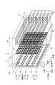
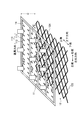
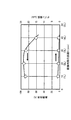
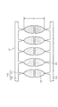
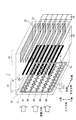
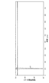
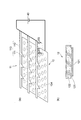
第1の実施の形態が適用される電気集塵機の一例を示す図である。It is a figure which shows an example of the electrical dust collector to which 1st Embodiment is applied. 帯電部の高圧電極及び対向電極のそれぞれの平面図である。(a)は高圧電極、(b)は対向電極である。It is each a top view of the high voltage electrode and counter electrode of a charging part. (A) is a high voltage electrode, (b) is a counter electrode. 帯電部を詳細に説明する断面図である。(a)は第1の実施の形態が適用される電気集塵機の帯電部、(b)は第1の実施の形態が適用されない比較例の電気集塵機の帯電部である。It is sectional drawing explaining a charging part in detail. (A) is the charging part of the electrostatic precipitator to which the first embodiment is applied, and (b) is the charging part of the electrostatic precipitator of the comparative example to which the first embodiment is not applied. 実施例1の電気集塵機及び比較例1の電気集塵機におけるオゾン濃度と集塵効率との関係を示す図である。It is a figure which shows the relationship between the ozone concentration and dust collection efficiency in the electrostatic precipitator of Example 1, and the electrostatic precipitator of the comparative example 1. 対向電極の抵抗体部を構成する材料(抵抗体部材料)とオゾン発生電圧(kV)及びオゾン発生電圧におけるイオン数(×10個/cm)との関係を示す図である。It is a diagram showing a relationship between a material constituting the resistance portion of the counter electrode (resistive body material) ozone generator voltage (kV) and the number of ions in the ozone generator voltage (× 10 3 cells / cm 3). 実施例3の電気集塵機の帯電部の斜視図である。It is a perspective view of the charging part of the electrostatic precipitator of Example 3. 実施例3の電気集塵機における高圧電極及び対向電極のそれぞれの平面図である。(a)は高圧電極、(b)は対向電極である。It is each top view of the high voltage electrode and counter electrode in the electric dust collector of Example 3. (A) is a high voltage electrode, (b) is a counter electrode. 実施例3の電気集塵機における集塵効率とオゾン濃度の関係を示す図である。It is a figure which shows the dust collection efficiency in the electric dust collector of Example 3, and the relationship of ozone concentration. 実施例4の電気集塵機の帯電部の斜視図である。It is a perspective view of the charging part of the electrostatic precipitator of Example 4. 実施例4の電気集塵機における高圧電極及び対向電極のそれぞれの平面図である。(a)は高圧電極、(b)は対向電極である。It is each top view of the high voltage electrode and counter electrode in the electric dust collector of Example 4. (A) is a high voltage electrode, (b) is a counter electrode. 実施例4の電気集塵機における集塵効率とオゾン濃度との関係を示す図である。It is a figure which shows the relationship between the dust collection efficiency in the electric dust collector of Example 4, and ozone concentration. 実施例4の電気集塵機の帯電部の変形例を示す図である。(a)は帯電部の斜視図、(b)は帯電部を対向電極側から見た図、(c)は対向電極12のXIIC−XIIC線での断面図である。It is a figure which shows the modification of the charging part of the electrostatic precipitator of Example 4. FIG. (A) is a perspective view of the charging unit, (b) is a view of the charging unit viewed from the counter electrode side, and (c) is a cross-sectional view of the counter electrode 12 taken along the line XIIC-XIIC. 実施例5の電気集塵機の帯電部を説明する図である。(a)は帯電部の斜視図、(b)は(a)のXIIIB−XIIIB線での断面図である。It is a figure explaining the charging part of the electrostatic precipitator of Example 5. FIG. (A) is a perspective view of a charging unit, (b) is a sectional view taken along line XIIIB-XIIIB of (a). 実施例5の電気集塵機の高圧電極及び対向電極のそれぞれの平面図である。(a)は高圧電極、(b)は対向電極である。It is each top view of the high voltage electrode and counter electrode of the electrostatic precipitator of Example 5. (A) is a high voltage electrode, (b) is a counter electrode. 電気集塵機の帯電部における高圧電極の変形例を示す図である。(a)は鋸歯を図2(a)と異なる配列で構成した図、(b)は鋸歯を図10(a)と異なる配列で構成した図である。It is a figure which shows the modification of the high voltage electrode in the charging part of an electrostatic precipitator. (A) is the figure which comprised the sawtooth by the arrangement | sequence different from FIG. 2 (a), (b) is the figure which comprised the sawtooth by the arrangement | sequence different from FIG. 10 (a). 電気集塵機の帯電部における高圧電極の他の変形例を示す図である。(a)はそれぞれが複数の針を備える複数の針列から構成され、針の先端が隣接する針列間で対向させて構成した図である。(b)は複数の針を備える複数の針列から構成され、針の先端が隣接する針列間で千鳥にして構成した図である。It is a figure which shows the other modification of the high voltage electrode in the charging part of an electrostatic precipitator. (A) is the figure comprised from the some needle row | line | column each provided with a some needle | hook, and making the front-end | tip of a needle | hook oppose between adjacent needle rows. (B) is the figure comprised from the several needle row | line | column provided with a several needle | hook, and staggered between the needle row | line | columns where the front-end | tip of a needle | hook is adjacent. 電気集塵機の帯電部における対向電極の変形例を説明する図である。It is a figure explaining the modification of the counter electrode in the charging part of an electrostatic precipitator. 第2の実施の形態が適用される電気集塵機の一例を示す図である。It is a figure which shows an example of the electrical dust collector to which 2nd Embodiment is applied. 鋸歯列における鋸歯の間隔Pに対する、電気集塵機の集塵効率及びオゾン濃度の関係を示す図である。It is a figure which shows the relationship between the dust collection efficiency of an electrostatic precipitator, and ozone concentration with respect to the space | interval P of the sawtooth in a sawtooth row | line | column. 鋸歯列間の距離Sに対する、電気集塵機の集塵効率及びオゾン濃度の関係を示す図である。It is a figure which shows the relationship between the dust collection efficiency of an electric dust collector, and ozone concentration with respect to the distance S between sawtooth rows. 帯電部における放電の様子を模式的に説明する図である。(a)は、高圧電極側から見た平面図、(b)は(a)のXXIB−XXIB線での断面図である。It is a figure which illustrates the mode of the discharge in a charging part typically. (A) is the top view seen from the high voltage electrode side, (b) is sectional drawing in the XXIB-XXIB line of (a). 第3の実施の形態が適用される電気集塵機の一例を示す図である。It is a figure which shows an example of the electrical dust collector to which 3rd Embodiment is applied. 帯電部における放電の様子を模式的に説明する図である。It is a figure which illustrates the mode of the discharge in a charging part typically. 第4の実施の形態が適用される電気集塵機の一例を示す図である。It is a figure which shows an example of the electrical dust collector to which 4th Embodiment is applied. 電気集塵機の帯電部に関する等価回路である。It is an equivalent circuit regarding the charging part of an electric dust collector. インダクタとダイオードとの並列回路による電流制限回路が接続された高圧電極の一例を示す図である。It is a figure which shows an example of the high voltage electrode to which the current limiting circuit by the parallel circuit of an inductor and a diode was connected. 抵抗による電流制限回路を含む帯電部の等価回路である。3 is an equivalent circuit of a charging unit including a current limiting circuit using a resistor. 実施例7の電気集塵機及び比較例3の電気集塵機のそれぞれの帯電部における電極間電圧の時間変化を示す図である。(a)は実施例7、(b)は比較例3である。It is a figure which shows the time change of the voltage between electrodes in each charging part of the electrostatic precipitator of Example 7, and the electrostatic precipitator of the comparative example 3. FIG. (A) is Example 7 and (b) is Comparative Example 3. 電流制限回路を含む帯電部の他の等価回路である。It is another equivalent circuit of the charging unit including a current limiting circuit. 実施例8の電気集塵機の帯電部における、鋸歯列毎に電流制限回路を接続した高圧電極の一例を示す図である。It is a figure which shows an example of the high voltage | pressure electrode which connected the current limiting circuit for every sawtooth row | line | column in the charging part of the electrostatic precipitator of Example 8. FIG. 実施例9の電気集塵機の帯電部における、鋸歯毎に電流制限回路を接続した高圧電極の一例を示す図である。It is a figure which shows an example of the high voltage | pressure electrode which connected the current limiting circuit for every sawtooth in the charging part of the electrostatic precipitator of Example 9. FIG. 第5の実施の形態が適用される電気集塵機における帯電部等価回路である。It is a charging part equivalent circuit in the electric dust collector to which the fifth embodiment is applied. 実施例10の電気集塵機の帯電部における電極間電圧の時間変化を説明する図である。It is a figure explaining the time change of the voltage between electrodes in the charging part of the electrostatic precipitator of Example 10. FIG. 実施例10の電気集塵機の帯電部における、短絡による電極間電圧の時間変化を説明する図である。It is a figure explaining the time change of the voltage between electrodes by the short circuit in the charging part of the electrostatic precipitator of Example 10. 電流制限回路を接続した高圧電極の一例を示す図である。It is a figure which shows an example of the high voltage electrode which connected the current limiting circuit. 電流制限回路を含む帯電部の他の等価回路である。(a)は図32の電流制限回路における二次電子電流制限部と短絡電流制限部との接続順序を入れ替えた場合である。(b)は電流制限回路を対向電極に接続した場合である。(c)は電流制限回路における二次電子電流制限部と短絡電流制限部との間に高圧電極と対向電極とを設けた場合である。It is another equivalent circuit of the charging unit including a current limiting circuit. (A) is a case where the connection order of the secondary electron current limiting unit and the short-circuit current limiting unit in the current limiting circuit of FIG. 32 is switched. (B) is a case where the current limiting circuit is connected to the counter electrode. (C) is a case where a high voltage electrode and a counter electrode are provided between the secondary electron current limiting unit and the short-circuit current limiting unit in the current limiting circuit. 第6の実施の形態が適用される電気集塵機の帯電部を説明するための模式図である。It is a schematic diagram for demonstrating the charging part of the electrostatic precipitator to which 6th Embodiment is applied. 実施例11の電気集塵機及び比較例4の電気集塵機のそれぞれの帯電部において発生するイオン数を示す図である。(a)は実施例11、(b)は比較例4である。It is a figure which shows the number of ions which generate | occur | produce in each charging part of the electrostatic precipitator of Example 11 and the electrostatic precipitator of the comparative example 4. (A) is Example 11 and (b) is Comparative Example 4. 実施例12とする電気集塵機における帯電部を説明する図である。(a)は帯電部の斜視図、(b)は対向電極のXXXIXB−XXXIXB線での断面図である。It is a figure explaining the charging part in the electrostatic precipitator made into Example 12. FIG. (A) is a perspective view of a charging unit, (b) is a cross-sectional view of the counter electrode taken along line XXXIXB-XXXIXB. 実施例13とする電気集塵機における帯電部を説明する図である。(a)は帯電部の斜視図、(b)は対向電極の一部の断面図である。It is a figure explaining the charging part in the electrostatic precipitator which is Example 13. FIG. (A) is a perspective view of a charging unit, (b) is a sectional view of a part of a counter electrode. 実施例14とする電気集塵機における帯電部を説明する図である。It is a figure explaining the charging part in the electrostatic precipitator made into Example 14. FIG. 実施例15の電気集塵機における帯電部を説明する図である。(a)は帯電部の斜視図、(b)は(a)のXLIIB−XLIIB線での断面図である。It is a figure explaining the charging part in the electrostatic precipitator of Example 15. FIG. (A) is a perspective view of a charging unit, (b) is a cross-sectional view taken along line XLIIB-XLIIB in (a). 高圧電極と対向電極の導体部との間に印加された電極間電圧(kV)と鋸歯の1本当たりのオゾン発生量(μg/h)との関係を説明する図である。It is a figure explaining the relationship between the electrode voltage (kV) applied between the high voltage electrode and the conductor part of a counter electrode, and the ozone generation amount (microgram / h) per one sawtooth. 実施例17とする電気集塵機における帯電部を説明する図である。(a)は帯電部の斜視図、(b)は対向電極の一部の断面図である。It is a figure explaining the charging part in the electrostatic precipitator which is Example 17. FIG. (A) is a perspective view of a charging unit, (b) is a sectional view of a part of a counter electrode. 実施例18とする電気集塵機における帯電部を説明する図である。(a)は帯電部の斜視図、(b)は(a)のXLVB−XLVB線での対向電極の断面図である。It is a figure explaining the charging part in the electrostatic precipitator made into Example 18. FIG. (A) is a perspective view of a charging unit, (b) is a cross-sectional view of a counter electrode taken along line XLVB-XLVB in (a). 実施例19とする電気集塵機における帯電部を説明する図である。(a)は帯電部の斜視図、(b)は(a)のXLVIB−XLVIB線での対向電極の断面図である。It is a figure explaining the charging part in the electrostatic precipitator which is Example 19. FIG. (A) is a perspective view of a charging unit, (b) is a cross-sectional view of a counter electrode taken along line XLVIB-XLVIB in (a). 第7の実施の形態が適用される電気集塵機の一例を示す図である。It is a figure which shows an example of the electrical dust collector to which 7th Embodiment is applied. 第8の実施の形態が適用される電気集塵機の一例を示す図である。It is a figure which shows an example of the electrical dust collector to which 8th Embodiment is applied. 実施例20、比較例6、7とする電気集塵機における帯電部の要部の斜視図である。(a)は、実施例20、(b)は、比較例6、(c)は、比較例7である。It is a perspective view of the principal part of the charging part in the electrostatic precipitator which makes Example 20 and Comparative Examples 6 and 7. FIG. (A) is Example 20, (b) is Comparative Example 6, and (c) is Comparative Example 7. 実施例20、比較例6、7とする電気集塵機におけるオゾン濃度及び粒子径毎に求めた集塵効率を説明する図である。It is a figure explaining the dust collection efficiency calculated | required for every ozone density | concentration and particle diameter in the electric dust collector made into Example 20 and Comparative Examples 6 and 7. FIG. 従高圧電極の作用を説明する図である。It is a figure explaining the effect | action of a subhigh voltage electrode. 第8の実施の形態が適用される電気集塵機の変形例を示す図である。It is a figure which shows the modification of the electrostatic precipitator to which 8th Embodiment is applied. 第9の実施の形態が適用される電気集塵機の変形例を示す図である。It is a figure which shows the modification of the electrostatic precipitator with which 9th Embodiment is applied. 実施例21とする電気集塵機における帯電部及び集塵部の要部の通風方向に対する断面図である。It is sectional drawing with respect to the ventilation direction of the principal part of the electrification part in the electrostatic precipitator made into Example 21 and a dust collection part. 実施例21及び比較例7とする電気集塵機における帯電部の要部の斜視図である。(a)は、実施例21、(b)は、比較例7である。It is a perspective view of the principal part of the charging part in the electric dust collector which is Example 21 and Comparative Example 7. (A) is Example 21, and (b) is Comparative Example 7. 実施例21、比較例7とする電気集塵機におけるオゾン濃度及び粒子径毎に求めた集塵効率を説明する図である。It is a figure explaining the dust collection efficiency calculated | required for every ozone density | concentration and particle diameter in the electric dust collector made into Example 21 and the comparative example 7. FIG.

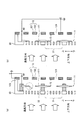
以下、添付図面を参照して、本発明の実施の形態について詳細に説明する。
[第1の実施の形態]
図1は、第1の実施の形態が適用される電気集塵機1の一例を示す図である。ここでは、筐体30を破線で示し、筐体30の内部に設けられた帯電部10及び集塵部20の構成が見えるようにしている。
電気集塵機1は、帯電部10と、集塵部20と、帯電部10及び集塵部20を収容する筐体30とを備えている。すなわち、電気集塵機1は、帯電部10と集塵部20とが分離した二段電気集塵方式である。
ここで、空気の流れ(通風)の方向(通風方向)は帯電部10から集塵部20に向かう方向に設定されている(図1の紙面の左から右)。通風は、集塵部20の通風方向下流側に設けられたファン(不図示)により行われる。
そして、説明の便宜上、図1に示すように、紙面の上下方向を上側及び下側、通風方向に対して上下方向と直交する左右方向を左側及び右側と表記する。
なお、通風が阻害されない限り、電気集塵機1は、どのような向きに置かれても構わない。
Embodiments of the present invention will be described below in detail with reference to the accompanying drawings.
[First Embodiment]
FIG. 1 is a diagram illustrating an example of an electrostatic precipitator 1 to which the first embodiment is applied. Here, the housing 30 is indicated by a broken line so that the configurations of the charging unit 10 and the dust collecting unit 20 provided inside the housing 30 can be seen.
The electric dust collector 1 includes a charging unit 10, a dust collecting unit 20, and a housing 30 that houses the charging unit 10 and the dust collecting unit 20. That is, the electrostatic precipitator 1 is a two-stage electrostatic precipitator system in which the charging unit 10 and the dust collecting unit 20 are separated.
Here, the direction of the air flow (ventilation) (ventilation direction) is set to the direction from the charging unit 10 to the dust collecting unit 20 (from the left to the right in FIG. 1). Ventilation is performed by a fan (not shown) provided on the downstream side of the dust collection unit 20 in the ventilation direction.
For convenience of explanation, as shown in FIG. 1, the vertical direction of the paper is expressed as the upper side and the lower side, and the horizontal direction perpendicular to the vertical direction with respect to the ventilation direction is expressed as the left side and the right side.
In addition, as long as ventilation is not inhibited, the electrostatic precipitator 1 may be placed in any direction.

(帯電部10)
帯電部10は、高圧電極11と、高圧電極11に対向する対向電極12とを備えている。なお、高圧電極11は、高電圧を印加される電極であるので、高電圧電極とも呼ばれ、放電を発生する電極であるので、放電電極とも呼ばれることがある。また、対向電極12は、接地(GND)されることがあるため、接地電極と呼ばれることがある。
そして、高圧電極11と対向電極12との間に、直流(DC)の高電圧が印加されることで、高圧電極11と対向電極12との間にコロナ放電(放電)が発生する。そして、発生したコロナ放電により、浮遊微粒子を帯電させる。
(Charging unit 10)
The charging unit 10 includes a high voltage electrode 11 and a counter electrode 12 facing the high voltage electrode 11. Note that the high voltage electrode 11 is an electrode to which a high voltage is applied, and thus is also referred to as a high voltage electrode. Further, since the counter electrode 12 may be grounded (GND), it is sometimes called a ground electrode.
A high direct current (DC) voltage is applied between the high voltage electrode 11 and the counter electrode 12, thereby generating a corona discharge (discharge) between the high voltage electrode 11 and the counter electrode 12. The suspended fine particles are charged by the generated corona discharge.

高圧電極11は、例えば、それぞれが尖った先端を有する鋸歯形状の部分111(以下では鋸歯111と表記する。)を複数備えた複数の鋸歯列113(図1では#1〜#5の5列)を備えている。それぞれの鋸歯列113の長手方向は、左右方向に向いている。図1では、上下方向における最も上側の鋸歯列113(図1では#1)は、下側を向いて配列された複数の鋸歯111(図1では10個)を備えている。上下方向における最も下側の鋸歯列113(図1では#5)は、上側を向いて配列された複数の鋸歯111(図1では10個)を備えている。間の鋸歯列113(図1では#2〜#4)は、上側を向いて配列された複数の鋸歯111(図1では10個)と、下側を向いて配列された複数の鋸歯111(図1では10個)とを備えている。
なお、鋸歯111及び/又はその先端は、電界集中を発生させる部位の一例である。
The high-voltage electrode 11 includes, for example, a plurality of sawtooth rows 113 (five rows of # 1 to # 5 in FIG. 1) having a plurality of sawtooth-shaped portions 111 each having a sharp tip (hereinafter referred to as a sawtooth 111). ). The longitudinal direction of each sawtooth row 113 is directed in the left-right direction. In FIG. 1, the uppermost sawtooth row 113 in the vertical direction (# 1 in FIG. 1) includes a plurality of saw teeth 111 (10 in FIG. 1) arranged facing downward. The lowermost sawtooth row 113 (# 5 in FIG. 1) in the vertical direction includes a plurality of sawtooths 111 (10 in FIG. 1) arranged facing upward. The sawtooth row 113 (# 2 to # 4 in FIG. 1) includes a plurality of saw teeth 111 (10 pieces in FIG. 1) arranged facing upward and a plurality of saw teeth 111 (10 in FIG. 1) arranged downward. 10 in FIG. 1).
Note that the sawtooth 111 and / or its tip is an example of a portion that generates electric field concentration.

なお、鋸歯列113の数及び鋸歯列113における鋸歯111の数は予め定められた数に設定される。   In addition, the number of the sawtooth rows 113 and the number of the sawtooth 111 in the sawtooth row 113 are set to a predetermined number.

それぞれの鋸歯列113における複数の鋸歯111は接続部112に接続されている。そして、それぞれの接続部112の端部は、絶縁性材料で構成された保持部14に固定されている。保持部14は、配線を備える回路基板(印刷配線板(PCB))を備えている。回路基板の配線を介して、鋸歯列113がDCの高電圧を供給する高電圧発生回路40の正極に接続されている。
なお、保持部14は、筐体30の一部であってもよい。
A plurality of saw teeth 111 in each saw tooth row 113 is connected to the connection portion 112. And the edge part of each connection part 112 is being fixed to the holding | maintenance part 14 comprised with the insulating material. The holding unit 14 includes a circuit board (printed wiring board (PCB)) including wiring. The sawtooth row 113 is connected to the positive electrode of the high voltage generation circuit 40 that supplies a high DC voltage via the wiring of the circuit board.
Note that the holding unit 14 may be a part of the housing 30.

それぞれの鋸歯111は、通風方向に対して、直交する方向に設けられている。さらに、それぞれの鋸歯111は、隣接する鋸歯列113の間、例えば鋸歯列113(#1)と鋸歯列113(#2)との間において、先端が互いに対向するように設けられている。
なお、それぞれの鋸歯111は、通風方向に対して、斜めの方向に設けられてもよい。すなわち、それぞれの鋸歯111は、通風方向に交差する方向に設けられている。
Each saw tooth 111 is provided in a direction orthogonal to the ventilation direction. Further, each of the saw teeth 111 is provided between the adjacent saw tooth rows 113, for example, between the saw tooth row 113 (# 1) and the saw tooth row 113 (# 2) so that the tips thereof face each other.
Each saw tooth 111 may be provided in an oblique direction with respect to the ventilation direction. That is, each saw tooth 111 is provided in a direction crossing the ventilation direction.

高圧電極11の鋸歯111と接続部112とは、導電性材料で一体として構成されている。なお、保持部14は、別部材とせず、鋸歯111、接続部112と一体に、導電性材料で構成されてもよい。   The sawtooth 111 and the connection portion 112 of the high-voltage electrode 11 are integrally formed of a conductive material. In addition, the holding | maintenance part 14 may be comprised with an electroconductive material integrally with the sawtooth 111 and the connection part 112, without making it a separate member.

対向電極12は、通風を確保するために、貫通した開口(孔)124を有する導電性材料で構成された部材と、その表面を覆うように設けられ、電流に対して抵抗として働く抵抗性材料で構成された部材(抵抗体)とを備えている(後述する図2の導体部121及び抵抗体部122参照)。そして、対向電極12は、高電圧発生回路40の負極に接続されている。
なお、抵抗性材料の部材は、放電電流を制限し、オゾンの発生を抑制する。よって、抵抗性材料の部材に対する体積抵抗率などの特性は、集塵効率とオゾン濃度との関係を考慮して設定される。
The counter electrode 12 is provided with a member made of a conductive material having an opening (hole) 124 penetrating therethrough and a resistive material that covers the surface of the member and serves as a resistance against current. (Refer to a conductor part 121 and a resistor part 122 in FIG. 2 to be described later). The counter electrode 12 is connected to the negative electrode of the high voltage generation circuit 40.
Note that the member of the resistive material limits the discharge current and suppresses the generation of ozone. Therefore, characteristics such as volume resistivity with respect to the member of the resistive material are set in consideration of the relationship between the dust collection efficiency and the ozone concentration.

図1では、対向電極12は、一例として導体部121が導電性材料で構成された金網(メッシュ)である。なお、図1(後述する図2(b)も同様。)では、網目(開口124)を大きく表記している。しかし、網目(開口124)の大きさは、高圧電極11との間で発生する放電を考慮して設定される。   In FIG. 1, the counter electrode 12 is, for example, a wire mesh (mesh) in which the conductor portion 121 is made of a conductive material. In FIG. 1 (the same applies to FIG. 2B, which will be described later), the mesh (opening 124) is shown greatly. However, the size of the mesh (opening 124) is set in consideration of the discharge generated between the high voltage electrode 11.

高圧電極11と対向電極12との間は、距離Gである。   The distance G is between the high voltage electrode 11 and the counter electrode 12.

(集塵部20)
集塵部20は、交互に積層された、表面が絶縁性材料の膜で被覆された平板状の高圧電極21と、平板状の対向電極22とを備えている。高圧電極21と対向電極22の間が通風方向となる。なお、対向電極22は、接地(GND)されることがあるため接地電極と呼ばれることがある。
高圧電極21と対向電極22との間に、高電圧発生回路50により、直流(DC)の高電圧が印加される。すると、帯電部10で帯電した浮遊微粒子が、静電気により対向電極22の表面に付着する。これにより、浮遊微粒子が集塵される。
(Dust collector 20)
The dust collection unit 20 includes a flat high voltage electrode 21 and a flat counter electrode 22 which are alternately stacked and whose surfaces are covered with a film of an insulating material. Between the high voltage electrode 21 and the counter electrode 22 is the ventilation direction. Note that the counter electrode 22 is sometimes referred to as a ground electrode because it may be grounded (GND).
A high voltage of direct current (DC) is applied between the high voltage electrode 21 and the counter electrode 22 by the high voltage generation circuit 50. Then, the suspended fine particles charged by the charging unit 10 adhere to the surface of the counter electrode 22 due to static electricity. Thereby, suspended fine particles are collected.

なお、高圧電極21の表面を覆う絶縁性材料の膜には、ポリエチレン、ポリエチレンテレフタレート(PET)、ポリテトラフルオロエチレン(PTFE)などを用い得る。   For the insulating material film covering the surface of the high voltage electrode 21, polyethylene, polyethylene terephthalate (PET), polytetrafluoroethylene (PTFE), or the like can be used.

集塵部20は、帯電部10の通風方向の下流側に設けられている。そして、集塵部20の高圧電極21と対向電極22の内、帯電部10に最も近い電極は、帯電部10を構成する部材の内、集塵部20に最も近い部材の端部から通風方向の下流側に5mm以上の離間距離で配置されているとよい。この関係は、以下に述べる他の実施の形態においても同様である。   The dust collection unit 20 is provided on the downstream side of the charging unit 10 in the ventilation direction. Of the high-voltage electrode 21 and the counter electrode 22 of the dust collection unit 20, the electrode closest to the charging unit 10 is the direction of ventilation from the end of the member constituting the charging unit 10 closest to the dust collection unit 20. It is good to arrange | position with the separation distance of 5 mm or more downstream. This relationship is the same in other embodiments described below.

(筐体30)
筐体30は、帯電部10と集塵部20とを収納する。そして、帯電部10に対向する前面部分には、複数の格子(グリル)31が設けられている。なお、格子31は、ユーザの帯電部10への接触を防ぎつつ、通風に対する抵抗が小さいように設けられることが好ましい。
筐体30は、例えば、ABS(アクリロニトリル、ブタジエン、スチレン共重合体)などの樹脂材料で構成されている。
(Case 30)
The housing 30 houses the charging unit 10 and the dust collecting unit 20. A plurality of grids (grills) 31 are provided on the front portion facing the charging unit 10. In addition, it is preferable that the lattice 31 is provided so that resistance to ventilation is small while preventing the user from contacting the charging unit 10.
The housing 30 is made of a resin material such as ABS (acrylonitrile, butadiene, styrene copolymer).

図2は、帯電部10の高圧電極11及び対向電極12のそれぞれの平面図である。図2(a)は高圧電極11、図2(b)は対向電極12である。
図2(a)に示すように、高圧電極11は、それぞれに鋸歯111が複数設けられた鋸歯列113(図2では#1〜#5)を備えている。そして、隣接する鋸歯列113間で、それぞれの鋸歯111の先端が対向する(向かい合う)ように設けられている。
そして、鋸歯111の先端から接続部112までの長さをL(長さL)、鋸歯列113における鋸歯111間の間隔(ピッチ)をP(間隔P)とする。さらに、隣接する鋸歯列113間において、鋸歯列に垂直な方向の鋸歯111の先端間の距離をS(距離S)とする。
FIG. 2 is a plan view of each of the high-voltage electrode 11 and the counter electrode 12 of the charging unit 10. 2A shows the high-voltage electrode 11, and FIG. 2B shows the counter electrode 12.
As shown in FIG. 2A, the high-voltage electrode 11 includes a sawtooth row 113 (# 1 to # 5 in FIG. 2) provided with a plurality of sawtooth 111 respectively. And between the adjacent sawtooth row | line | column 113, it provides so that the front-end | tip of each sawtooth 111 may oppose (opposite).
The length from the tip of the saw tooth 111 to the connection portion 112 is L (length L), and the interval (pitch) between the saw teeth 111 in the saw tooth row 113 is P (interval P). Furthermore, the distance between the tips of the saw teeth 111 in the direction perpendicular to the saw tooth rows between the adjacent saw tooth rows 113 is S (distance S).

図2(b)に示すように、対向電極12は、一例として導電性材料で構成された金網(メッシュ)である導体部121と、その表面を覆う抵抗体部122とを備えている。そして、上側と下側の端部が、導体部121の表面を露出させた導体露出領域123となっている。なお、左右側の端部にも導体部121の表面を露出させた導体露出領域123を設けてもよい。
一方、対向電極12の一部の端部のみに、導体部121の表面を露出させた導体露出領域123を設けてもよい。
導体露出領域123は、形成された抵抗体部122を除去して形成してもよく、抵抗体部122を形成しない(例えば、塗布しない)ように形成してもよい。
As shown in FIG. 2B, the counter electrode 12 includes, as an example, a conductor portion 121 that is a wire mesh (mesh) made of a conductive material, and a resistor portion 122 that covers the surface thereof. The upper and lower end portions are conductor exposed regions 123 where the surface of the conductor portion 121 is exposed. In addition, you may provide the conductor exposure area | region 123 which exposed the surface of the conductor part 121 also in the edge part of the right-and-left side.
On the other hand, a conductor exposed region 123 in which the surface of the conductor 121 is exposed may be provided only at a part of the end of the counter electrode 12.
The conductor exposed region 123 may be formed by removing the formed resistor portion 122 or may be formed so as not to form (for example, not apply) the resistor portion 122.

対向電極12に、抵抗体部122を設けるのは、放電電流を制限し、オゾンの発生を抑制するためである。よって、後述するように、抵抗体部122を構成する部材は、比誘電率が3以上で、体積抵抗率が1014Ω・cm以上且つ1018Ω・cm以下であることが好ましい。なお、抵抗体部122の厚さによって、厚さ方向の抵抗値が変化する。したがって、抵抗体部122の厚さにより、放電電流の値が設定できる。
なお、体積抵抗率が1014Ω・cmとは、1014Ω・cm台であることを意味する。他の体積抵抗率の値についても同様である。
The reason why the resistor portion 122 is provided on the counter electrode 12 is to limit the discharge current and suppress the generation of ozone. Therefore, as will be described later, the member constituting the resistor portion 122 preferably has a relative dielectric constant of 3 or more and a volume resistivity of 10 14 Ω · cm or more and 10 18 Ω · cm or less. Note that the resistance value in the thickness direction varies depending on the thickness of the resistor portion 122. Therefore, the value of the discharge current can be set depending on the thickness of the resistor portion 122.
The volume resistivity of 10 14 Ω · cm means that it is on the order of 10 14 Ω · cm. The same applies to other values of volume resistivity.

図3は、帯電部10を詳細に説明する断面図である。図3(a)は第1の実施の形態が適用される電気集塵機1の帯電部10、図3(b)は第1の実施の形態が適用されない電気集塵機1の帯電部10である。
高圧電極11は、複数の鋸歯111を備えている。図3(a)、(b)では、それぞれの鋸歯111は、電気的につながっていないように見える。しかし、図1、図2で説明したように、高圧電極11は、電気的につながっている。
対向電極12は、導体部121と導体部121の表面を覆うように設けられた抵抗体部122とを備えている。なお、図3(a)、(b)では、導体部121は、互いに電気的につながっていないように見える。しかし、図1、図2で説明したように、導体部121は、導電性材料で構成された金網(メッシュ)であるので、電気的につながっている。
FIG. 3 is a cross-sectional view illustrating the charging unit 10 in detail. 3A shows the charging unit 10 of the electrostatic precipitator 1 to which the first embodiment is applied, and FIG. 3B shows the charging unit 10 of the electrostatic precipitator 1 to which the first embodiment is not applied.
The high voltage electrode 11 includes a plurality of saw teeth 111. In FIGS. 3A and 3B, each saw tooth 111 appears to be not electrically connected. However, as described in FIGS. 1 and 2, the high voltage electrode 11 is electrically connected.
The counter electrode 12 includes a conductor portion 121 and a resistor portion 122 provided so as to cover the surface of the conductor portion 121. In FIGS. 3A and 3B, the conductor parts 121 appear not to be electrically connected to each other. However, as described with reference to FIGS. 1 and 2, the conductor 121 is electrically connected because it is a wire mesh (mesh) made of a conductive material.

図3(a)に示す第1の実施の形態が適用される電気集塵機1の帯電部10では、高圧電極11は、電気絶縁性の部材(絶縁体)で構成された絶縁スペーサ32を介して筐体30に取り付けられている。よって、高圧電極11は、筐体30に直接接触していない。なお、保持部14が、絶縁スペーサ32であってもよく、保持部14が、絶縁スペーサ32を介して筐体30に取り付けられてもよい。
絶縁スペーサ32としては、電気絶縁性が高いものであればよく、セラミクス、樹脂材料、空気などで構成されていることが好ましい。
なお、絶縁スペーサ32は、絶縁部材の一例である。
In the charging unit 10 of the electrostatic precipitator 1 to which the first embodiment shown in FIG. 3A is applied, the high-voltage electrode 11 is interposed via an insulating spacer 32 formed of an electrically insulating member (insulator). It is attached to the housing 30. Therefore, the high voltage electrode 11 is not in direct contact with the housing 30. The holding unit 14 may be an insulating spacer 32, and the holding unit 14 may be attached to the housing 30 via the insulating spacer 32.
The insulating spacer 32 only needs to have a high electrical insulating property, and is preferably made of ceramics, a resin material, air, or the like.
The insulating spacer 32 is an example of an insulating member.

一方、対向電極12は、導体部121を露出させた導体露出領域123が筐体30と電気的に接触するように筐体30に取り付けられている。そして、その導体露出領域123で接地端子Eに接続されている。なお、接地端子Eは、接地されなくてもよい。   On the other hand, the counter electrode 12 is attached to the housing 30 so that the conductor exposed region 123 where the conductor portion 121 is exposed is in electrical contact with the housing 30. The conductor exposed region 123 is connected to the ground terminal E. The ground terminal E may not be grounded.

また、筐体30などの樹脂材料で構成された部材(樹脂部材)は、鋸歯111の先端より、予め定められた距離rの範囲に設けられていない。ここでの樹脂部材は、筐体30を構成する部材に限らず、筐体30内に設けられるものを含む。   Further, a member (resin member) made of a resin material such as the housing 30 is not provided within a predetermined distance r from the tip of the saw tooth 111. The resin member here is not limited to a member constituting the housing 30, but includes a member provided in the housing 30.

一方、図3(b)に示す比較例1の電気集塵機1における帯電部10では、対向電極12の端部は、導体部121を露出させていない。つまり、比較例1の電気集塵機1では、対向電極12は導体露出領域を備えていない。
そして、高圧電極11は、筐体30に直接接触するように取り付けられている。
一方、対向電極12は、抵抗体部122を介して、筐体30と接触するよう取り付けられている。そして、対向電極12は、筐体30と接する部分以外において、接地端子Eに接続されている。なお、接地端子Eは、接地されなくてもよい。
On the other hand, in the charging part 10 in the electrostatic precipitator 1 of the comparative example 1 shown in FIG. 3B, the end part of the counter electrode 12 does not expose the conductor part 121. That is, in the electrostatic precipitator 1 of the comparative example 1, the counter electrode 12 does not include a conductor exposed region.
The high voltage electrode 11 is attached so as to be in direct contact with the housing 30.
On the other hand, the counter electrode 12 is attached so as to come into contact with the housing 30 via the resistor portion 122. The counter electrode 12 is connected to the ground terminal E at a portion other than the portion in contact with the housing 30. The ground terminal E may not be grounded.

(実施例1)
次に、第1の実施の形態が適用される電気集塵機1(実施例1の電気集塵機1)及び第1の実施の形態が適用されない電気集塵機1(比較例1の電気集塵機1)の集塵効率とオゾン濃度を測定した結果を説明する。
実施例1の電気集塵機1及び比較例1の電気集塵機1は、それぞれの帯電部10が図3に示したように異なる。しかし、他の構成は同じである。
Example 1
Next, the dust collector 1 (electric dust collector 1 of Example 1) to which the first embodiment is applied and the dust collector 1 (electric dust collector 1 of Comparative Example 1) to which the first embodiment is not applied. The results of measuring efficiency and ozone concentration will be described.
The electrostatic precipitator 1 of Example 1 and the electrostatic precipitator 1 of the comparative example 1 differ in each charging part 10 as shown in FIG. However, other configurations are the same.

電気集塵機1の帯電部10は、通風方向から見た高圧電極11の保持部14の大きさを、左右方向で約400mm、上下方向で約300mmとした。そして、筐体30の表面には、40mm×125mmの開口部が複数設けられるように格子31を配置した。   In the charging unit 10 of the electrostatic precipitator 1, the size of the holding unit 14 of the high-voltage electrode 11 viewed from the ventilation direction is about 400 mm in the left-right direction and about 300 mm in the up-down direction. And the grating | lattice 31 was arrange | positioned so that the opening part of 40 mm x 125 mm might be provided in the surface of the housing | casing 30. FIG.

帯電部10における高圧電極11の鋸歯111及び接続部112は、厚さ0.5mmの板状のステンレススチール(SUS)で構成した。そして、鋸歯111は、先端から接続部112までの長さを約10mmとした。そして、鋸歯列113間の鋸歯111の先端間の距離Sを約30mmとした。
帯電部10における対向電極12は、導体部121を開口率87.1%のSUSで構成された金網(メッシュ)とした。導体部121の表面を覆う抵抗体部122は、厚さ約50μmのポリイミド樹脂とした。このポリイミド樹脂は、比誘電率が3.3、体積抵抗率が1016Ω・cmであった。
高圧電極11と対向電極12との距離Gは、約5mmとした。
そして、高圧電極11と対向電極との間に、約4kVのDC電圧を印加してコロナ放電を発生させた。
The saw-tooth 111 and the connection part 112 of the high-voltage electrode 11 in the charging unit 10 are made of plate-shaped stainless steel (SUS) having a thickness of 0.5 mm. And the sawtooth 111 made the length from the front-end | tip to the connection part 112 about 10 mm. The distance S between the tips of the saw teeth 111 between the saw tooth rows 113 was about 30 mm.
For the counter electrode 12 in the charging unit 10, the conductor 121 is a wire mesh (mesh) made of SUS with an aperture ratio of 87.1%. The resistor part 122 covering the surface of the conductor part 121 was made of polyimide resin having a thickness of about 50 μm. This polyimide resin had a relative dielectric constant of 3.3 and a volume resistivity of 10 16 Ω · cm.
The distance G between the high voltage electrode 11 and the counter electrode 12 was about 5 mm.
Then, a DC voltage of about 4 kV was applied between the high voltage electrode 11 and the counter electrode to generate corona discharge.

集塵部20における高圧電極21及び対向電極22は、通風方向の幅が20mm、通風方向と直交する方向の長さが約400mmとした。そして、高圧電極21と対向電極22の間隔は、約1.5mmとした。そして、高圧電極21と対向電極22との間に、約6kVのDC電圧を印加した。   The high-voltage electrode 21 and the counter electrode 22 in the dust collecting unit 20 have a width in the ventilation direction of 20 mm and a length in a direction orthogonal to the ventilation direction of about 400 mm. And the space | interval of the high voltage electrode 21 and the counter electrode 22 was about 1.5 mm. Then, a DC voltage of about 6 kV was applied between the high voltage electrode 21 and the counter electrode 22.

そして、実施例1の電気集塵機1では、筐体30などを構成する樹脂部材を、鋸歯111の先端から約5mm(距離r)の範囲に設けないようにした。   And in the electrostatic precipitator 1 of Example 1, the resin member which comprises the housing | casing 30 etc. was not provided in the range of about 5 mm (distance r) from the front-end | tip of the sawtooth 111. FIG.

図4は、実施例1の電気集塵機1及び比較例1の電気集塵機1における集塵効率とオゾン濃度との関係を示す図である。通風方向の風速は、1m/sである。
ここで、オゾン濃度は、オゾン濃度計を用い、オゾン濃度計が計測するオゾン量とオゾン濃度計が取り込む空気の量から求めた。また、集塵効率は、電気集塵機1の通風方向の上流(電気集塵機1に入る前)と下流(電気集塵機1から出た後)とにおいて、浮遊微粒子の数をパーティクルカウンタにより計測して求めた。
FIG. 4 is a diagram illustrating the relationship between the dust collection efficiency and the ozone concentration in the electrostatic precipitator 1 of Example 1 and the electrostatic precipitator 1 of Comparative Example 1. The wind speed in the ventilation direction is 1 m / s.
Here, the ozone concentration was determined from the amount of ozone measured by the ozone concentration meter and the amount of air taken in by the ozone concentration meter using an ozone concentration meter. The dust collection efficiency was obtained by measuring the number of suspended particulates with a particle counter upstream (before entering the electrostatic dust collector 1) and downstream (after exiting the electrostatic dust collector 1) in the ventilation direction of the electrostatic dust collector 1. .

図4から分かるように、実施例1の電気集塵機1は、ほぼ100%の集塵効率が得られる状態で動作させても、オゾン濃度が2.0ppb以下であった。この値は、環境基準値(0.05ppm)を大きく下回る。   As can be seen from FIG. 4, even when the electrostatic precipitator 1 of Example 1 was operated in a state where almost 100% dust collection efficiency was obtained, the ozone concentration was 2.0 ppb or less. This value is far below the environmental standard value (0.05 ppm).

一方、比較例1の電気集塵機1では、集塵効率が約50%で飽和した。そして、集塵効率が約50%であるにも関わらず、オゾン濃度が実施例1の電気集塵機1に比べて、大きい。なお、比較例1の電気集塵機1においても、測定範囲における最大のオゾン濃度は、2.0ppbであって、環境基準値(0.05ppm)を下回る。
実施例1の電気集塵機1及び比較例1の電気集塵機1は、オゾン濃度が環境基準値に比べ低く抑えられている。これは、帯電部10の対向電極12が、導体部121の表面を覆う抵抗体部122を備えることで、放電電流が制限されたためと考えられる。
On the other hand, in the electric dust collector 1 of Comparative Example 1, the dust collection efficiency was saturated at about 50%. Even though the dust collection efficiency is about 50%, the ozone concentration is higher than that of the electric dust collector 1 of the first embodiment. Note that also in the electrostatic precipitator 1 of Comparative Example 1, the maximum ozone concentration in the measurement range is 2.0 ppb, which is lower than the environmental standard value (0.05 ppm).
In the electrostatic precipitator 1 of Example 1 and the electrostatic precipitator 1 of Comparative Example 1, the ozone concentration is suppressed to be lower than the environmental standard value. This is thought to be because the discharge current was limited because the counter electrode 12 of the charging unit 10 was provided with the resistor portion 122 that covers the surface of the conductor portion 121.

一方、実施例1の電気集塵機1と比較例1の電気集塵機1とで集塵効率が異なるのは、比較例1の電気集塵機1は、実施例1の電気集塵機1に比べて、筐体30が静電気で帯電しやすいためと考えらえる。
比較例1の電気集塵機1では、高圧電極11が筐体30に直接接触している。そして、筐体30を構成する樹脂材料により、高電圧発生回路40から供給されるDCの高電圧が絶縁されている。このため、筐体30は接地端子Eに接続されていない。
On the other hand, the electrostatic precipitator 1 of Example 1 and the electrostatic precipitator 1 of Comparative Example 1 have different dust collection efficiencies in the electrostatic precipitator 1 of Comparative Example 1 compared to the electrostatic precipitator 1 of Example 1 in the housing 30. This can be thought of as being easily charged by static electricity.
In the electric dust collector 1 of the comparative example 1, the high voltage electrode 11 is in direct contact with the housing 30. The DC high voltage supplied from the high voltage generation circuit 40 is insulated by the resin material constituting the housing 30. For this reason, the housing 30 is not connected to the ground terminal E.

筐体30を構成する樹脂材料は、電気抵抗率が高く電気を流しにくい。このため、筐体30の表面は静電気で帯電しやすい。筐体30が接地電極に接続されていないため、帯電した静電気は逃げられない。すなわち、筐体30の帯電、特に高圧電極11と接する近傍の筐体30の帯電により、浮遊微粒子の帯電効率が悪くなって、集塵効率が低下したと考えられる。   The resin material constituting the housing 30 has a high electrical resistivity and is difficult to pass electricity. For this reason, the surface of the housing 30 is easily charged with static electricity. Since the housing 30 is not connected to the ground electrode, the charged static electricity cannot escape. That is, it is considered that the charging efficiency of the floating fine particles is deteriorated due to the charging of the casing 30, particularly the charging of the casing 30 in the vicinity of the high voltage electrode 11, and the dust collection efficiency is lowered.

一方、実施例1の電気集塵機1では、絶縁スペーサ32を介して高圧電極11を筐体30に取り付けている。よって、高圧電極11と筐体30とは電気的に接触しない。また、筐体30が対向電極12に接続されているため、帯電した静電気が逃げることができる。さらに、高圧電極11である鋸歯111の先端から予め定められた距離r(実施例1では5mm)の範囲に、筐体30などを構成する樹脂部材を設けていない。
よって、筐体30が静電気で帯電することが抑制されて、浮遊微粒子の帯電が阻害されにくくなり、集塵効率が高くなったと考えられる。
On the other hand, in the electric dust collector 1 of Example 1, the high voltage electrode 11 is attached to the housing 30 via the insulating spacer 32. Therefore, the high voltage electrode 11 and the housing 30 are not in electrical contact. Moreover, since the housing | casing 30 is connected to the counter electrode 12, the charged static electricity can escape. Furthermore, the resin member which comprises the housing | casing 30 etc. is not provided in the range of predetermined distance r (5 mm in Example 1) from the front-end | tip of the sawtooth 111 which is the high voltage electrode 11. FIG.
Therefore, it is considered that the case 30 is suppressed from being charged by static electricity, and the charging of the floating fine particles is hardly inhibited, and the dust collection efficiency is increased.

以上説明したように、第1の実施の形態が適用される電気集塵機1では、帯電部10の対向電極12を、導体部121と導体部121の表面を覆うように設けた抵抗体部122とで構成している。よって、放電電流が、抵抗体部122を設けない場合に比べて、小さく抑えられ、オゾン濃度が低く抑えられる。
そして、帯電部10の高圧電極11は、絶縁スペーサ32を介して筐体30に固定されている。さらに、高圧電極11の鋸歯111の先端から予め定められた距離rの範囲に、筐体30などを構成する樹脂部材が設けられていない。さらに、対向電極12は、導体露出領域123において筐体30と導通するように電気的に接触させている。これらにより、筐体30が静電気で帯電することを抑制し、集塵効率を向上させている。
また、帯電部10の高圧電極11は、鋸歯列113間で鋸歯111のそれぞれの先端を対向させているので、一方の向き(例えば下側)の鋸歯111を用いない場合に比べ、放電が発生する領域が広くなっている。
As described above, in the electrostatic precipitator 1 to which the first embodiment is applied, the counter electrode 12 of the charging unit 10 is provided with the conductor part 121 and the resistor part 122 provided so as to cover the surface of the conductor part 121. It consists of. Therefore, the discharge current can be suppressed smaller than that in the case where the resistor portion 122 is not provided, and the ozone concentration can be suppressed low.
The high-voltage electrode 11 of the charging unit 10 is fixed to the housing 30 via an insulating spacer 32. Furthermore, the resin member which comprises the housing | casing 30 etc. is not provided in the range of predetermined distance r from the front-end | tip of the sawtooth 111 of the high voltage electrode 11. FIG. Furthermore, the counter electrode 12 is in electrical contact with the housing 30 in the conductor exposed region 123. As a result, the housing 30 is prevented from being charged by static electricity and the dust collection efficiency is improved.
Further, since the high-voltage electrode 11 of the charging unit 10 has the tips of the saw blades 111 opposed to each other between the saw tooth rows 113, discharge occurs compared to the case where the saw blade 111 in one direction (for example, the lower side) is not used. The area to do is wide.

第1の実施の形態が適用される電気集塵機1では、帯電部10において、高圧電極11と対向電極12とを、通風方向に配置している。さらに、高圧電極11の放電を発生させる部分を鋸歯111とし、鋸歯111を通風方向に対して、直交又は傾けて配置している。よって、高圧電極11と対向電極12との距離Gを、例えば5mmと、短く設定できる。これにより、電気集塵機1が小型化できる。   In the electrostatic precipitator 1 to which the first embodiment is applied, the high-voltage electrode 11 and the counter electrode 12 are arranged in the ventilation direction in the charging unit 10. Further, the portion of the high-voltage electrode 11 that generates discharge is a saw tooth 111, and the saw tooth 111 is arranged orthogonally or inclined to the ventilation direction. Therefore, the distance G between the high-voltage electrode 11 and the counter electrode 12 can be set as short as, for example, 5 mm. Thereby, the electric dust collector 1 can be reduced in size.

ちなみに、第1の実施の形態が適用される電気集塵機1と異なって、対向電極12の導体部121の表面を覆うように設ける抵抗体部122を設けずに、高圧電極11と対向電極12との間を近づけていくと、放電電流が増加して、オゾンの発生が増加してしまう。   Incidentally, unlike the electrostatic precipitator 1 to which the first embodiment is applied, the high-voltage electrode 11 and the counter electrode 12 are provided without providing the resistor portion 122 provided to cover the surface of the conductor portion 121 of the counter electrode 12. As the distance between them increases, the discharge current increases and the generation of ozone increases.

(実施例2)
前述したように、対向電極12は、導体部121と導体部121の表面を覆う抵抗体部122とで構成されている。
実施例2では、対向電極12の表面を覆う抵抗体部122の材料について説明する。
(Example 2)
As described above, the counter electrode 12 includes the conductor portion 121 and the resistor portion 122 that covers the surface of the conductor portion 121.
In Example 2, the material of the resistor portion 122 that covers the surface of the counter electrode 12 will be described.

図5は、対向電極12の抵抗体部122を構成する材料(抵抗体部材料)とオゾン発生電圧(kV)及びオゾン発生電圧におけるイオン数(×10個/cm)との関係を示す図である。なお、図5では、抵抗体部122を構成する材料(抵抗体部材料)の特性として、体積抵抗率(Ω・cm)及び比誘電率を示している。さらに、図5では、高圧電極11と対向電極12との距離G(mm)を示している。ここでは、高圧電極11と対向電極12との距離Gは5mmに固定されている。 FIG. 5 shows the relationship between the material (resistor part material) constituting the resistor part 122 of the counter electrode 12, the ozone generation voltage (kV), and the number of ions at the ozone generation voltage (× 10 3 / cm 3 ). FIG. In FIG. 5, volume resistivity (Ω · cm) and relative dielectric constant are shown as the characteristics of the material (resistor part material) constituting the resistor part 122. Further, FIG. 5 shows a distance G (mm) between the high-voltage electrode 11 and the counter electrode 12. Here, the distance G between the high-voltage electrode 11 and the counter electrode 12 is fixed to 5 mm.

オゾン発生電圧とは、高圧電極11と対向電極12との間に印加したDC電圧を徐々に上げた(増加させた)場合に、オゾン濃度計によりオゾンの発生が検出され始める電圧である。
また、オゾン発生電圧におけるイオン数とは、高圧電極11と対向電極12との間にオゾン発生電圧を印加した場合に、高圧電極11と対向電極12との間に発生するイオンの個数(×10個/cm)である。イオン数は、イオンカウンタにて計測した。
電気集塵機1では、オゾン発生電圧が高く、且つオゾン発生電圧において発生するイオン数が大きいことが好ましい。
The ozone generation voltage is a voltage at which generation of ozone begins to be detected by the ozone concentration meter when the DC voltage applied between the high voltage electrode 11 and the counter electrode 12 is gradually increased (increased).
The number of ions in the ozone generation voltage is the number of ions (× 10) generated between the high voltage electrode 11 and the counter electrode 12 when the ozone generation voltage is applied between the high voltage electrode 11 and the counter electrode 12. 3 / cm 3 ). The number of ions was measured with an ion counter.
In the electric dust collector 1, it is preferable that the ozone generation voltage is high and the number of ions generated at the ozone generation voltage is large.

ここでは、帯電部10における対向電極12の抵抗体部122を構成する材料を除いて、図1に示した電気集塵機1を用いた。帯電部10の高圧電極11は、鋸歯111を有し、対向電極12は、導体部121が導電性材料で構成された金網(メッシュ)である。
そして、高圧電極11は絶縁スペーサ32を介して筐体30に取り付けられている。対向電極12は、導体露出領域123が筐体30と接続されるように取り付けられ、取り付けられた部分が接地端子Eに接続されている。
Here, the electrostatic precipitator 1 shown in FIG. 1 was used except the material which comprises the resistor part 122 of the counter electrode 12 in the charging part 10. The high-voltage electrode 11 of the charging unit 10 has a sawtooth 111, and the counter electrode 12 is a wire mesh (mesh) in which the conductor unit 121 is made of a conductive material.
The high voltage electrode 11 is attached to the housing 30 via an insulating spacer 32. The counter electrode 12 is attached such that the conductor exposed region 123 is connected to the housing 30, and the attached portion is connected to the ground terminal E.

抵抗体部122の材料には、“なし”、アルキッド樹脂(Alkyd resin)”、“アクリル樹脂(Acrylic resin)”、“ポリイミド樹脂(Polyimide)”、“ポリエステル樹脂(Polyester)”、“PTFE(ポリテトラフルオロエチレン(polytetrafluoroethylene))”を用いた。
抵抗体部122の厚さは、それぞれ約50μmとした。
The material of the resistor 122 is “None”, “Alkyd resin”, “Acrylic resin”, “Polyimide”, “Polyester”, “PTFE” (polyethylene). Tetrafluoroethylene (polytetrafluoroethylene) ”was used.
The thickness of the resistor portion 122 was about 50 μm.

抵抗体部122が“なし”の場合には、オゾン発生電圧が3.2kVで、オゾン発生電圧におけるイオン数は0個であった。すなわち、高圧電極11と対向電極12との間のDC電圧を徐々に上げていくと、3.2kVのときに、オゾンが発生し始めた。しかし、オゾン発生電圧ではイオンは発生しなかった。   When the resistor portion 122 was “none”, the ozone generation voltage was 3.2 kV, and the number of ions in the ozone generation voltage was 0. That is, when the DC voltage between the high voltage electrode 11 and the counter electrode 12 was gradually increased, ozone began to be generated at 3.2 kV. However, no ions were generated at the ozone generation voltage.

抵抗体部122がアルキッド樹脂の場合には、オゾン発生電圧が4.0kVで、オゾン発生電圧におけるイオン数は1040×10個/cmであった。すなわち、高圧電極11と対向電極12との間のDC電圧を徐々に増加させていくと、4.0kVのときに、オゾンが発生し始めた。しかし、イオンは、オゾン発生電圧未満のDC電圧において発生し始めていた。 When the resistor part 122 was alkyd resin, the ozone generation voltage was 4.0 kV and the number of ions at the ozone generation voltage was 1040 × 10 3 ions / cm 3 . That is, when the DC voltage between the high voltage electrode 11 and the counter electrode 12 was gradually increased, ozone began to be generated at 4.0 kV. However, ions began to be generated at DC voltages below the ozone generation voltage.

抵抗体部122がアクリル樹脂の場合には、オゾン発生電圧が4.5kVで、オゾン発生電圧におけるイオン数は1400×10個/cmであった。すなわち、高圧電極11と対向電極12との間のDC電圧を徐々に上げていくと、6.0kVのときに、オゾンが発生し始めた。しかし、イオンは、オゾン発生電圧未満のDC電圧において発生し始めていた。 When the resistor 122 was an acrylic resin, the ozone generation voltage was 4.5 kV, and the number of ions in the ozone generation voltage was 1400 × 10 3 pieces / cm 3 . That is, when the DC voltage between the high-voltage electrode 11 and the counter electrode 12 was gradually increased, ozone began to be generated at 6.0 kV. However, ions began to be generated at DC voltages below the ozone generation voltage.

抵抗体部122がポリイミド樹脂の場合には、オゾン発生電圧が6.0kVで、オゾン発生電圧におけるイオン数は1600×10個/cmであった。すなわち、高圧電極11と対向電極12との間のDC電圧を徐々に上げていくと、4.5kVのときに、オゾンが発生し始めた。しかし、イオンは、オゾン発生電圧未満のDC電圧において発生し始めていた。 When the resistor 122 is a polyimide resin, the ozone generation voltage was 6.0 kV, and the number of ions in the ozone generation voltage was 1600 × 10 3 / cm 3 . That is, when the DC voltage between the high voltage electrode 11 and the counter electrode 12 was gradually increased, ozone began to be generated at 4.5 kV. However, ions began to be generated at DC voltages below the ozone generation voltage.

そして、抵抗体部122がポリエステル樹脂又はPTFEの場合には、高圧電極11と対向電極12との間のDC電圧を10kVまで印加しても、オゾンは発生せず、イオンも発生しなかった。なお、ポリエステル樹脂の場合、導体露出領域123を設けることにより、高圧電極11と対向電極12との間のDC電圧を10kVまで印加しても、オゾンは発生しないが、イオンは発生させることができた。すなわち、高圧電極11と対向電極12との間のDC電圧を10kVとした場合、イオン数は2000×10個/cmであった。 And when the resistor part 122 was polyester resin or PTFE, even if the DC voltage between the high voltage electrode 11 and the counter electrode 12 was applied up to 10 kV, ozone was not generated and ions were not generated. In the case of polyester resin, by providing the conductor exposed region 123, even if the DC voltage between the high voltage electrode 11 and the counter electrode 12 is applied up to 10 kV, ozone is not generated, but ions can be generated. It was. That is, when the DC voltage between the high voltage electrode 11 and the counter electrode 12 was 10 kV, the number of ions was 2000 × 10 3 ions / cm 3 .

以上のことから、図5に示した抵抗体部122の材料(抵抗体部材料)として、ポリイミド樹脂が最もオゾン発生電圧が高く、且つオゾン発生電圧におけるイオン数が大きい。すなわち、ポリイミド樹脂が抵抗体部122の材料としては、最も好ましい。次に、アクリル樹脂、アルキッド樹脂が、この順に好ましい。さらに、導体露出領域123を設けることにより、ポリエステル樹脂も用いることができる。
また、特性から見ると、比誘電率が3以上であって、体積抵抗率が、1012Ω・cm以上且つ1018Ω・cm以下であることが好ましい。体積抵抗率については、1014Ω・cm以上且つ1018Ω・cm以下がより好ましい。
なお、導体露出領域123を備えない場合には、抵抗体部122の体積抵抗率が1017Ω・cmを超えると、抵抗体部122は、絶縁体として機能し、高圧電極11と対向電極12との間における放電の発生を阻害すると考えられる。したがって、この場合には導体露出領域123を設けることが必要となる。
From the above, polyimide resin has the highest ozone generation voltage as the material of the resistor section 122 (resistor section material) shown in FIG. 5, and the number of ions in the ozone generation voltage is large. That is, polyimide resin is most preferable as a material for the resistor portion 122. Next, acrylic resin and alkyd resin are preferable in this order. Furthermore, a polyester resin can also be used by providing the conductor exposed region 123.
From the viewpoint of characteristics, it is preferable that the relative dielectric constant is 3 or more and the volume resistivity is 10 12 Ω · cm or more and 10 18 Ω · cm or less. The volume resistivity is more preferably 10 14 Ω · cm to 10 18 Ω · cm.
When the conductor exposed region 123 is not provided, when the volume resistivity of the resistor portion 122 exceeds 10 17 Ω · cm, the resistor portion 122 functions as an insulator, and the high-voltage electrode 11 and the counter electrode 12 It is thought that the occurrence of discharge between the two is inhibited. Therefore, in this case, it is necessary to provide the conductor exposed region 123.

(実施例3)
実施例3では、帯電部10における対向電極12が抵抗体部122を有する場合と有しない場合とにおける集塵効率とオゾン濃度との関係を説明する。ここで説明する電気集塵機1を実施例3の電気集塵機1と表記する。
図6は、実施例3の電気集塵機1の帯電部10の斜視図である。図1に示す電気集塵機1では、通風方向が紙面において右から左に向かう方向であった。しかし、図6では、通風方向を、紙面において上から下に向かう方向に記載している。
(Example 3)
In the third embodiment, the relationship between the dust collection efficiency and the ozone concentration in the case where the counter electrode 12 in the charging unit 10 has the resistor portion 122 and in the case where it does not have will be described. The electrostatic precipitator 1 described here is referred to as an electrostatic precipitator 1 according to the third embodiment.
FIG. 6 is a perspective view of the charging unit 10 of the electrostatic precipitator 1 according to the third embodiment. In the electrostatic precipitator 1 shown in FIG. 1, the ventilation direction is a direction from right to left on the paper surface. However, in FIG. 6, the ventilation direction is shown in the direction from the top to the bottom in the drawing.

そして、電気集塵機1の高圧電極11は、図1、図2に示した構成である。すなわち、それぞれが複数の鋸歯111を備えた複数の鋸歯列113を備えている。鋸歯111は、鋸歯列113間で先端が互いに対向するように配列されている。   And the high voltage electrode 11 of the electrostatic precipitator 1 is the structure shown in FIG. 1, FIG. That is, a plurality of saw tooth rows 113 each having a plurality of saw teeth 111 are provided. The saw teeth 111 are arranged so that the tips thereof oppose each other between the saw tooth rows 113.

一方、電気集塵機1の対向電極12は、導体部121がエキスパンドメタルで構成されている。エキスパンドメタルは、導電性材料で構成された板に切れ目を入れ、引き延ばすことにより菱形の開口124が形成される金網状の部材である。   On the other hand, as for the counter electrode 12 of the electrostatic precipitator 1, the conductor part 121 is comprised by the expanded metal. The expanded metal is a wire mesh member in which a diamond-shaped opening 124 is formed by cutting and stretching a plate made of a conductive material.

図7は、実施例3の電気集塵機における高圧電極11及び対向電極12のそれぞれの平面図である。図7(a)は、高圧電極11、図7(b)は、対向電極12である。
図7(a)に示す高圧電極11は、図2(a)に示した高圧電極11と同じである。
図7(b)に示す対向電極12は、エキスパンドメタルから構成された導体部121と、その表面を覆うように設けられた抵抗体部122とを備えている。なお、導体部121の一部(上下方向の上側及び下側)は、抵抗体部122を備えない導体露出領域123となっている。
そして、高圧電極11は絶縁スペーサ32を介して筐体30に取り付けられている。対向電極12は、導体露出領域123が筐体30と接続されるように取り付けられ、取り付けられた部分が接地端子Eに接続されている(図3参照)。
FIG. 7 is a plan view of each of the high-voltage electrode 11 and the counter electrode 12 in the electric dust collector of the third embodiment. 7A shows the high-voltage electrode 11, and FIG. 7B shows the counter electrode 12.
The high voltage electrode 11 shown in FIG. 7A is the same as the high voltage electrode 11 shown in FIG.
The counter electrode 12 shown in FIG. 7B includes a conductor portion 121 made of expanded metal and a resistor portion 122 provided so as to cover the surface thereof. Part of the conductor 121 (upper and lower sides in the vertical direction) is a conductor exposed region 123 that does not include the resistor 122.
The high voltage electrode 11 is attached to the housing 30 via an insulating spacer 32. The counter electrode 12 is attached so that the conductor exposed region 123 is connected to the housing 30, and the attached portion is connected to the ground terminal E (see FIG. 3).

高圧電極11の保持部14の大きさを、左右方向で約400mm、上下方向で約300mmとした。
そして、高圧電極11は、厚さ0.5mmのSUSで構成した。鋸歯列113間における鋸歯111の先端間の距離Sを、約30mmとした。そして、高圧電極11は、5列の鋸歯列113(#1〜#5)を備えているとした。
The size of the holding portion 14 of the high-voltage electrode 11 was about 400 mm in the left-right direction and about 300 mm in the up-down direction.
The high voltage electrode 11 was made of SUS having a thickness of 0.5 mm. The distance S between the tips of the saw blades 111 between the saw tooth rows 113 was about 30 mm. The high-voltage electrode 11 includes five rows of sawtooth rows 113 (# 1 to # 5).

対向電極12の導体部121は、SUSのエキスパンドメタルで構成し、開口124の寸法を4mm×8mmとした。
対向電極12の導体部121を覆う、抵抗体部122は厚さ50μmのポリイミド樹脂とした。
なお、抵抗体部122として用いたポリイミド樹脂は、誘電率3.3、体積抵抗率1016Ω・cmである。
高圧電極11と対向電極12との距離Gは、5mmとした。
The conductor portion 121 of the counter electrode 12 is made of SUS expanded metal, and the size of the opening 124 is 4 mm × 8 mm.
The resistor part 122 covering the conductor part 121 of the counter electrode 12 was made of polyimide resin having a thickness of 50 μm.
The polyimide resin used as the resistor 122 has a dielectric constant of 3.3 and a volume resistivity of 10 16 Ω · cm.
The distance G between the high voltage electrode 11 and the counter electrode 12 was 5 mm.

高圧電極11と対向電極12との間に、約4kVのDC電圧を印加すると、イオンが発生し始め、浮遊微粒子の帯電が可能になった。
そして、図1に示したように、通風方向の下流側に、集塵部20を設け、帯電部10及び集塵部20に通電しながら、通風させることで、空気中の浮遊微粒子を除去した。
When a DC voltage of about 4 kV was applied between the high voltage electrode 11 and the counter electrode 12, ions began to be generated, and the floating fine particles could be charged.
And as shown in FIG. 1, the dust collection part 20 was provided in the downstream of the ventilation direction, and it was made to ventilate, supplying the charging part 10 and the dust collection part 20, and the airborne particulate was removed. .

図8は、実施例3の電気集塵機1における集塵効率とオゾン濃度の関係を示す図である。図8では、上記の構成による電気集塵機1を実施例3として示し、帯電部10の対向電極12に抵抗体部122を設けない電気集塵機1を比較例2として示した。なお、比較例2の電気集塵機1でも、帯電部10の対向電極12は、筐体30と接続されるように取り付けられ、取り付けられた部分が接地端子Eに接続されている。   FIG. 8 is a diagram illustrating the relationship between the dust collection efficiency and the ozone concentration in the electric dust collector 1 of the third embodiment. In FIG. 8, the electrostatic precipitator 1 configured as described above is shown as Example 3, and the electrostatic precipitator 1 in which the resistor part 122 is not provided on the counter electrode 12 of the charging unit 10 is shown as Comparative Example 2. In the electrostatic precipitator 1 of Comparative Example 2, the counter electrode 12 of the charging unit 10 is attached so as to be connected to the housing 30, and the attached part is connected to the ground terminal E.

実施例3の電気集塵機1では、ほぼ100%の集塵効率が得られる状態で動作させても、オゾン濃度が3ppb以下であった。この値は、環境基準値(0.05ppm)を大きく下回る。
一方、比較例2の電気集塵機1では、ほぼ100%の集塵効率が得られる状態で動作させると、オゾン濃度が7ppbを超える。この値は、環境基準値(0.05ppm)を下回るが、実施例3の電気集塵機1の2倍以上である。
The electric dust collector 1 of Example 3 had an ozone concentration of 3 ppb or less even when operated in a state where nearly 100% dust collection efficiency was obtained. This value is far below the environmental standard value (0.05 ppm).
On the other hand, when the electrostatic precipitator 1 of Comparative Example 2 is operated in a state where almost 100% dust collection efficiency is obtained, the ozone concentration exceeds 7 ppb. This value is lower than the environmental standard value (0.05 ppm), but is twice or more that of the electrostatic precipitator 1 of Example 3.

以上説明したように、実施例3の電気集塵機1は、帯電部10の対向電極12に抵抗体部122を備えることで、オゾン濃度を低く抑えつつ高い集塵効率が得られる。   As described above, the electrostatic precipitator 1 according to the third embodiment includes the resistor unit 122 in the counter electrode 12 of the charging unit 10, so that high dust collection efficiency can be obtained while keeping the ozone concentration low.

(実施例4)
ここでは、電気集塵機1と帯電部10の高圧電極11の形状が異なる場合における集塵効率とオゾン濃度との関係について説明する。ここで説明する電気集塵機1を実施例4の電気集塵機1と表記する。
Example 4
Here, the relationship between dust collection efficiency and ozone concentration when the shape of the high-voltage electrode 11 of the electrostatic precipitator 1 and the charging unit 10 is different will be described. The electrostatic precipitator 1 described here is referred to as an electrostatic precipitator 1 according to the fourth embodiment.

図9は、実施例4の電気集塵機1の帯電部10の斜視図である。図9でも、通風方向を、上下方向に記載している。
電気集塵機1の高圧電極11は、それぞれが複数の鋸歯111を備えた複数の鋸歯列113を備えている。それぞれの鋸歯列113は、上方向と下方向とを向く鋸歯111を備えている。鋸歯111の先端は、鋸歯列113間で互いに千鳥(スタガ)になるように配列されている。すなわち、鋸歯111の先端は、鋸歯列113間で互いに対向せず、一方の鋸歯列113の鋸歯111の先端の間に、他方の鋸歯列113の鋸歯111の先端が配列されている。すなわち、鋸歯列113間において、鋸歯111が列方向に互いにずれて配置されている。
一方、電気集塵機1の対向電極12は、実施例3と同様に、導体部121がエキスパンドメタルである。
FIG. 9 is a perspective view of the charging unit 10 of the electrostatic precipitator 1 according to the fourth embodiment. Also in FIG. 9, the ventilation direction is described in the vertical direction.
The high-voltage electrode 11 of the electric dust collector 1 includes a plurality of sawtooth rows 113 each having a plurality of sawtooth 111. Each sawtooth row 113 includes a sawtooth 111 facing upward and downward. The tips of the saw teeth 111 are arranged in a staggered manner between the saw tooth rows 113. That is, the tips of the saw teeth 111 do not oppose each other between the saw tooth rows 113, and the tips of the saw teeth 111 of the other saw tooth row 113 are arranged between the tips of the saw teeth 111 of one saw tooth row 113. That is, between the sawtooth rows 113, the sawtooth 111 is displaced from each other in the row direction.
On the other hand, in the counter electrode 12 of the electrostatic precipitator 1, the conductor portion 121 is an expanded metal as in the third embodiment.

図10は、実施例4の電気集塵機における高圧電極11及び対向電極12のそれぞれの平面図である。図10(a)は高圧電極11、図10(b)は対向電極12である。
図10(a)に示すように、すべての鋸歯列113の上下方向に鋸歯111を設けることにより、鋸歯111の数が、実施例3の場合より、多くなっている。
そして、高圧電極11は絶縁スペーサ32を介して筐体30に取り付けられている。対向電極12は、導体露出領域123が筐体30と接続されるように取り付けられ、取り付けられた部分が接地端子Eに接続されている。
FIG. 10 is a plan view of each of the high-voltage electrode 11 and the counter electrode 12 in the electric dust collector of the fourth embodiment. 10A shows the high-voltage electrode 11, and FIG. 10B shows the counter electrode 12.
As shown in FIG. 10A, by providing the saw teeth 111 in the vertical direction of all the saw tooth rows 113, the number of the saw teeth 111 is larger than in the case of the third embodiment.
The high voltage electrode 11 is attached to the housing 30 via an insulating spacer 32. The counter electrode 12 is attached such that the conductor exposed region 123 is connected to the housing 30, and the attached portion is connected to the ground terminal E.

高圧電極11の保持部14の大きさを、左右方向で約400mm、上下方向で約300mmとした。
そして、高圧電極11は、厚さ0.5mmのSUSで構成した。鋸歯列113間の鋸歯111の先端間の距離Sは、20mmとした。高圧電極11は、5列の鋸歯列113(#1〜#5)を備えるとした。
対向電極12は、導体部121をSUSのエキスパンドメタルで構成し、開口124の寸法を約4mm×約8mmとした。そして、対向電極12の導体部121の表面を覆う抵抗体部122は、厚さ約50μmのポリイミド樹脂とした。このポリイミド樹脂は、誘電率3.3、体積抵抗率1016Ω・cmであった。
The size of the holding portion 14 of the high-voltage electrode 11 was about 400 mm in the left-right direction and about 300 mm in the up-down direction.
The high voltage electrode 11 was made of SUS having a thickness of 0.5 mm. The distance S between the tips of the saw teeth 111 between the saw tooth rows 113 was 20 mm. The high voltage electrode 11 includes five rows of sawtooth rows 113 (# 1 to # 5).
In the counter electrode 12, the conductor 121 is made of SUS expanded metal, and the size of the opening 124 is about 4 mm × about 8 mm. And the resistor part 122 which covers the surface of the conductor part 121 of the counter electrode 12 was made into polyimide resin about 50 micrometers thick. This polyimide resin had a dielectric constant of 3.3 and a volume resistivity of 10 16 Ω · cm.

図11は、実施例4の電気集塵機1における集塵効率とオゾン濃度との関係を示す図である。なお、ここでは、上記の構成による電気集塵機1を実施例4として示している。また、実施例3の電気集塵機1及び比較例2の電気集塵機1を合わせて示している。
図11から分かるように、実施例4の電気集塵機1では、ほぼ100%の集塵効率が得られる状態で動作させても、オゾン濃度が2ppb以下であった。このオゾン濃度は、実施例3の電気集塵機1よりも低い。
これは、高圧電極11の鋸歯列113における鋸歯111を、鋸歯列113間において、互いに千鳥に配列したことによると考えられる。すなわち、高圧電極11と対向電極12との間において、コロナ放電が形成される領域(範囲)が、鋸歯列113間で鋸歯111を互いに対向させた場合に比べ、広がるためと考えられる。
FIG. 11 is a diagram illustrating the relationship between the dust collection efficiency and the ozone concentration in the electric dust collector 1 of the fourth embodiment. Here, the electrostatic precipitator 1 having the above configuration is shown as a fourth embodiment. Moreover, the electrostatic precipitator 1 of Example 3 and the electrostatic precipitator 1 of the comparative example 2 are shown collectively.
As can be seen from FIG. 11, the electric dust collector 1 of Example 4 had an ozone concentration of 2 ppb or less even when operated in a state where a dust collection efficiency of almost 100% was obtained. This ozone concentration is lower than that of the electric dust collector 1 of the third embodiment.
This is considered to be because the saw-tooth 111 in the saw-tooth row 113 of the high-voltage electrode 11 is arranged in a staggered manner between the saw-tooth rows 113. That is, it is considered that a region (range) where corona discharge is formed between the high voltage electrode 11 and the counter electrode 12 is wider than when the saw blades 111 are opposed to each other between the saw tooth rows 113.

以上説明したように、実施例4の電気集塵機1は、高圧電極11の形状を変えることで、オゾン濃度をより低く抑えつつ高い集塵効率が得られる。   As described above, the electrostatic precipitator 1 according to the fourth embodiment can obtain a high dust collection efficiency while keeping the ozone concentration lower by changing the shape of the high voltage electrode 11.

図12は、実施例4の電気集塵機1の帯電部10の変形例を示す図である。図12(a)は帯電部10の斜視図、図12(b)は帯電部10を対向電極12側から見た図、図12(c)は対向電極12のXIIC−XIIC線での断面図である。
対向電極12の導体部121は、複数の平板で構成され、複数の平板を構成する各平板の表面に抵抗体部122が積層されている。そして、各平板は、各鋸歯列113と対になるように配置されている。さらに、各平板は、高圧電極11から距離Gの平面内に設けられている。このとき、導体部121の幅Wは、導体部121と対向する鋸歯列113において、導体部121の幅方向における鋸歯111の先端間の距離Qよりも小さいことが好ましい。
なお、導体部121の一部(鋸歯列113側に対して裏面側)は、抵抗体部122を備えない導体露出領域123となっている。そして、対向電極12は、導体露出領域123が筐体30と接続されるように取り付けられ、取り付けられた部分が接地端子Eに接続されている。なお、導体露出領域123は、高圧電極11との間で放電が直接生じないように、設けられている。すなわち、対向電極12の導体露出領域123は、絶縁破壊を起こさない部分で露出させており、高圧電極11と対向電極12の導体露出領域123とは、絶縁距離が保持されている。
FIG. 12 is a diagram illustrating a modification of the charging unit 10 of the electrostatic precipitator 1 according to the fourth embodiment. 12A is a perspective view of the charging unit 10, FIG. 12B is a diagram of the charging unit 10 viewed from the counter electrode 12, and FIG. 12C is a cross-sectional view of the counter electrode 12 taken along the line XIIC-XIIC. It is.
The conductor portion 121 of the counter electrode 12 is composed of a plurality of flat plates, and a resistor portion 122 is laminated on the surface of each flat plate constituting the plurality of flat plates. Each flat plate is arranged to be paired with each sawtooth row 113. Further, each flat plate is provided in a plane at a distance G from the high-voltage electrode 11. At this time, the width W of the conductor portion 121 is preferably smaller than the distance Q between the tips of the saw teeth 111 in the width direction of the conductor portion 121 in the sawtooth row 113 facing the conductor portion 121.
A part of the conductor portion 121 (on the back surface side with respect to the sawtooth row 113 side) is a conductor exposed region 123 that does not include the resistor portion 122. The counter electrode 12 is attached so that the conductor exposed region 123 is connected to the housing 30, and the attached portion is connected to the ground terminal E. The conductor exposed region 123 is provided so that a discharge is not directly generated between the conductor exposed region 123 and the high voltage electrode 11. That is, the conductor exposed region 123 of the counter electrode 12 is exposed at a portion where dielectric breakdown does not occur, and the insulation distance is maintained between the high voltage electrode 11 and the conductor exposed region 123 of the counter electrode 12.

(実施例5)
実施例1〜実施例4においては、電気集塵機1の帯電部10における高圧電極11に鋸歯111を使用した。
次に、電気集塵機1の帯電部10における高圧電極11にワイヤ114を用いた場合を説明する。ここで説明する電気集塵機1を実施例5の電気集塵機1と表記する。
(Example 5)
In Examples 1 to 4, the sawtooth 111 was used for the high voltage electrode 11 in the charging unit 10 of the electrostatic precipitator 1.
Next, the case where the wire 114 is used for the high voltage electrode 11 in the charging unit 10 of the electrostatic precipitator 1 will be described. The electrostatic precipitator 1 described here is referred to as an electrostatic precipitator 1 according to the fifth embodiment.

図13は、実施例5の電気集塵機1の帯電部10を説明する図である。図13(a)は帯電部10の斜視図、図13(b)は図13(a)のXIIIB−XIIIB線での断面図である。図13(a)でも、通風方向を、紙面において、上から下の方向に記載している。
図13(a)に示すように、電気集塵機1の帯電部10の高圧電極11は、複数のワイヤ114を備えている。複数のワイヤ114は、左右方向に設けられている。そして、複数のワイヤ114の両端部が、保持部14に固定されている。そして、複数のワイヤ114は、保持部14が備える回路基板に設けられた配線を介して、DC電圧が給電される。
帯電部10の対向電極12は、導体部121が導電性材料で構成された金網(メッシュ)である。そして、対向電極12は、導体部121の表面を覆うように設けられた抵抗体部122を備えている(後述する図14参照)。
FIG. 13 is a diagram illustrating the charging unit 10 of the electrostatic precipitator 1 according to the fifth embodiment. 13A is a perspective view of the charging unit 10, and FIG. 13B is a cross-sectional view taken along line XIIIB-XIIIB of FIG. 13A. Also in FIG. 13A, the ventilation direction is described from the top to the bottom in the drawing.
As shown in FIG. 13A, the high-voltage electrode 11 of the charging unit 10 of the electrostatic precipitator 1 includes a plurality of wires 114. The plurality of wires 114 are provided in the left-right direction. Then, both end portions of the plurality of wires 114 are fixed to the holding portion 14. The plurality of wires 114 are fed with a DC voltage via wiring provided on a circuit board provided in the holding unit 14.
The counter electrode 12 of the charging unit 10 is a wire mesh (mesh) in which the conductor 121 is made of a conductive material. And the counter electrode 12 is provided with the resistor part 122 provided so that the surface of the conductor part 121 might be covered (refer FIG. 14 mentioned later).

図13(b)の断面図に示すように、対向電極12は、複数のワイヤ114をそれぞれ囲むように、半径Mの半円筒状に曲げられている。ここでは、半径Mは、ワイヤ114間の距離Sの1/2に設定されている。なお、対向電極12は複数のワイヤ114を囲む半円筒状に構成されていてもよい。
そして、高圧電極11のワイヤ114は、絶縁スペーサ32を介して筐体30に取り付けられている。なお、保持部14が絶縁スペーサ32を介して筐体30に取り付けられてもよい。また、保持部14が筐体30の一部であってもよい。
一方、対向電極12は、導体露出領域123が筐体30と接続されるように取り付けられ、取り付けられた部分が接地端子Eに接続されている。
As shown in the cross-sectional view of FIG. 13B, the counter electrode 12 is bent into a semi-cylindrical shape having a radius M so as to surround each of the plurality of wires 114. Here, the radius M is set to ½ of the distance S between the wires 114. The counter electrode 12 may be formed in a semi-cylindrical shape surrounding the plurality of wires 114.
The wire 114 of the high voltage electrode 11 is attached to the housing 30 via the insulating spacer 32. Note that the holding unit 14 may be attached to the housing 30 via the insulating spacer 32. The holding unit 14 may be a part of the housing 30.
On the other hand, the counter electrode 12 is attached such that the conductor exposed region 123 is connected to the housing 30, and the attached portion is connected to the ground terminal E.

図14は、実施例5の電気集塵機1の高圧電極11及び対向電極12のそれぞれの平面図である。図14(a)は高圧電極11、図14(b)は対向電極12である。
図14(a)に示す高圧電極11は、複数のワイヤ114を備えている。
図14(b)に示す対向電極12は、導体部121が導電性材料で構成された金網(メッシュ)である。そして、導体部121の表面を覆う抵抗体部122を備えている。なお、図13(b)に示したように、対向電極12を半円筒状にした際、対向電極12が筐体30と接触する部分は、抵抗体部122を備えない導体露出領域123となっている。
FIG. 14 is a plan view of each of the high-voltage electrode 11 and the counter electrode 12 of the electrostatic precipitator 1 according to the fifth embodiment. 14A shows the high-voltage electrode 11, and FIG. 14B shows the counter electrode 12.
The high voltage electrode 11 shown in FIG. 14A includes a plurality of wires 114.
The counter electrode 12 shown in FIG. 14B is a wire mesh (mesh) in which the conductor portion 121 is made of a conductive material. And the resistor part 122 which covers the surface of the conductor part 121 is provided. As shown in FIG. 13B, when the counter electrode 12 is formed in a semi-cylindrical shape, a portion where the counter electrode 12 contacts the housing 30 becomes a conductor exposed region 123 that does not include the resistor portion 122. ing.

実施例5の電気集塵機1においても、オゾン濃度を低く抑えつつ、高い集塵効率が得られた。
これは、帯電部10の対向電極12が、導体部121の表面を覆う抵抗体部122を備えることで、放電電流が制限されたことによる。そして、複数のワイヤ114のそれぞれに半円筒状に対向電極12を設けたことにより、コロナ放電がそれぞれのワイヤ114を取り巻く空間において発生していることによると考えられる。
Also in the electric dust collector 1 of Example 5, high dust collection efficiency was obtained, suppressing ozone concentration low.
This is because the counter electrode 12 of the charging unit 10 includes the resistor part 122 that covers the surface of the conductor part 121, thereby limiting the discharge current. It is considered that corona discharge is generated in the space surrounding each wire 114 by providing the counter electrode 12 in a semi-cylindrical shape on each of the plurality of wires 114.

(帯電部10における高圧電極11の変形例)
図15は、電気集塵機1の帯電部10における高圧電極11の変形例を示す図である。図15(a)は鋸歯111を図2(a)と異なる配列で構成した図、図15(b)は鋸歯111を図10(a)と異なる配列で構成した図である。
(Modification of High Voltage Electrode 11 in Charging Unit 10)
FIG. 15 is a diagram illustrating a modification of the high voltage electrode 11 in the charging unit 10 of the electrostatic precipitator 1. 15A is a diagram in which the sawtooth 111 is configured in a different arrangement from that in FIG. 2A, and FIG. 15B is a diagram in which the sawtooth 111 is configured in an arrangement different from that in FIG.

まず、図15(a)を説明する。
図2(a)では、最も上側及び最も下側の鋸歯列113(図2では#1、#5)の接続部112を保持部14に接近又は接触させて設けた。このため、最も上側及び最も下側の鋸歯列113(図2(a)では#1、#5)では、上方向又は下方向のいずれか一方の鋸歯111しか設けなかった。
これに対し、図15(a)に示す高圧電極11では、すべての鋸歯列113が上方向及び下方向の両方の鋸歯111を備えている。
First, FIG. 15A will be described.
In FIG. 2A, the connection part 112 of the uppermost and lowermost sawtooth rows 113 (# 1, # 5 in FIG. 2) is provided close to or in contact with the holding part. For this reason, in the uppermost and lowermost sawtooth rows 113 (# 1 and # 5 in FIG. 2A), only either the upper or lower sawtooth 111 is provided.
On the other hand, in the high voltage electrode 11 shown in FIG. 15A, all the sawtooth rows 113 include both the upward and downward sawtooth 111.

次に、図15(b)を説明する。
図10(a)では、すべての鋸歯列113が上方向及び下方向の両方の鋸歯111を備えていた。
これに対し、図15(b)に示す高圧電極11では、最も上側及び最も下側の鋸歯列113(図15(b)では#1、#6)の接続部112を保持部14に接近又は接触させて設けている。このため、最も上側及び最も下側の鋸歯列113(図15(b)では#1、#6)では、上方向又は下方向のいずれか一方の鋸歯111しか設けていない。
Next, FIG. 15B will be described.
In FIG. 10A, all the sawtooth rows 113 are provided with both the upward and downward sawtooth 111.
On the other hand, in the high-voltage electrode 11 shown in FIG. 15B, the connection portion 112 of the uppermost and lowermost sawtooth rows 113 (# 1 and # 6 in FIG. 15B) approaches the holding portion 14 or Provided in contact. For this reason, in the uppermost and lowermost sawtooth rows 113 (# 1, # 6 in FIG. 15B), only one of the upper and lower sawtooth 111 is provided.

これらの高圧電極11を実施例1、実施例3、実施例4のそれぞれの電気集塵機1に適用しても、オゾン濃度を低く抑えつつ、高い集塵効率が得られる。   Even when these high-voltage electrodes 11 are applied to the electric dust collectors 1 of Example 1, Example 3, and Example 4, high dust collection efficiency can be obtained while keeping the ozone concentration low.

図16は、電気集塵機1の帯電部10における高圧電極11の他の変形例を示す図である。図16(a)はそれぞれが複数の針115を備える複数の針列117から構成され、針115の先端が隣接する針列間で対向させて構成した図である。図16(b)は複数の針115を備える複数の針列117から構成され、針115の先端が隣接する針列117間で千鳥にして構成した図である。
針115及び/又はその先端は、電界集中を発生させる部位の一例である。
FIG. 16 is a diagram illustrating another modification of the high-voltage electrode 11 in the charging unit 10 of the electrostatic precipitator 1. FIG. 16A is a diagram in which a plurality of needle rows 117 each having a plurality of needles 115 are configured, and the tips of the needles 115 are opposed to each other between adjacent needle rows. FIG. 16 (b) is a diagram composed of a plurality of needle rows 117 having a plurality of needles 115, and the tips of the needles 115 are staggered between adjacent needle rows 117.
The needle 115 and / or its tip is an example of a site that generates electric field concentration.

図16(a)は、図2(a)に示す高圧電極11の鋸歯111を、針115に置き換えたものである。なお、針115は、先端が尖った針形状の部材である。そして、針列117において複数の針115を接続する接続部116は、例えば、配線が形成された回路基板であって、複数の針115と配線とが接続されている。
図16(b)は、図10(a)に示す高圧電極11の鋸歯111を針115に置き換えたものである。他の構成は、図10(a)と同様であるので説明を省略する。
FIG. 16A shows a configuration in which the saw blade 111 of the high voltage electrode 11 shown in FIG. The needle 115 is a needle-shaped member with a sharp tip. And the connection part 116 which connects the some needle | hook 115 in the needle row | line | column 117 is a circuit board in which wiring was formed, for example, Comprising: The some needle | hook 115 and wiring are connected.
FIG. 16B is obtained by replacing the saw blade 111 of the high voltage electrode 11 shown in FIG. The other configuration is the same as that shown in FIG.

これらの高圧電極11を実施例1、実施例3、実施例4のそれぞれの電気集塵機1に適用しても、オゾン濃度を低く抑えつつ、高い集塵効率が得られる。
なお、図16(a)、(b)に示した針115の配列を、それぞれ図15(a)、(b)に示した鋸歯111の配列に変更してもよい。
Even when these high-voltage electrodes 11 are applied to the electric dust collectors 1 of Example 1, Example 3, and Example 4, high dust collection efficiency can be obtained while keeping the ozone concentration low.
Note that the arrangement of the needles 115 shown in FIGS. 16 (a) and 16 (b) may be changed to the arrangement of the saw teeth 111 shown in FIGS. 15 (a) and 15 (b), respectively.

また、高圧電極11は、高圧電極11の鋸歯111又は針115の代わりに、例えば、導電性のカーボン線を結束した刷毛(ブラシ)形状であってもよい。なお、刷毛(ブラシ)形状の部分及び/又はその先端は、電界集中を発生させる部位の一例である。   Moreover, the high voltage electrode 11 may have a brush (brush) shape in which conductive carbon wires are bound, for example, instead of the sawtooth 111 or the needle 115 of the high voltage electrode 11. The brush-shaped part and / or the tip thereof is an example of a part that generates electric field concentration.

(帯電部10における対向電極12の変形例)
図17は、電気集塵機1の帯電部10における対向電極12の変形例を説明する図である。
図17に示す対向電極12は、複数の開口124を設けた導電性材料で構成された板である導体部121とその表面に設けられた抵抗体部122とを備えている。開口124は導体部121である板を貫通して設けられている。なお、導体部121の一部(左右方向の両端部)は、抵抗体部122を備えない導体露出領域123となっている。
そして、対向電極12は、導体露出領域123が筐体30と接続されるように取り付けられ、取り付けられた部分が接地端子Eに接続される。
なお、抵抗体部122は、高圧電極11と対向電極12との間の放電電流を抑制するために設けられている。よって、少なくとも、高圧電極11と対向電極12の導体部121との間で放電が発生しないことが求められる。このことから、抵抗体部122は、少なくとも高圧電極11と向かい合う側の導体部121(板)の表面を覆うように設けられていることが好ましい。
(Modification of counter electrode 12 in charging unit 10)
FIG. 17 is a diagram illustrating a modification of the counter electrode 12 in the charging unit 10 of the electrostatic precipitator 1.
The counter electrode 12 shown in FIG. 17 includes a conductor portion 121 that is a plate made of a conductive material provided with a plurality of openings 124 and a resistor portion 122 provided on the surface thereof. The opening 124 is provided through a plate which is the conductor portion 121. Part of the conductor 121 (both ends in the left-right direction) is a conductor exposed region 123 that does not include the resistor 122.
The counter electrode 12 is attached so that the conductor exposed region 123 is connected to the housing 30, and the attached portion is connected to the ground terminal E.
The resistor 122 is provided to suppress a discharge current between the high voltage electrode 11 and the counter electrode 12. Therefore, it is required that at least no discharge occurs between the high-voltage electrode 11 and the conductor portion 121 of the counter electrode 12. Therefore, it is preferable that the resistor portion 122 is provided so as to cover at least the surface of the conductor portion 121 (plate) on the side facing the high-voltage electrode 11.

上記において説明した高圧電極11と対向電極12とを、それぞれ組み合わせて用いてもよい。   The high voltage electrode 11 and the counter electrode 12 described above may be used in combination.

また、実施例1〜5に示した数値は、一例であって、これらに限定されないことは明らかである。   Moreover, the numerical values shown in Examples 1 to 5 are merely examples, and it is obvious that the numerical values are not limited thereto.

[第2の実施の形態]
第2の実施の形態では、高圧電極11が複数の鋸歯111をそれぞれが備えた複数の鋸歯列113で構成されているとして、鋸歯111の配置に設定される要件について説明する。ここでは、鋸歯列113間において、鋸歯111の先端が互いにずれて配置されているとする。例えば、鋸歯列113間において、鋸歯111の先端が千鳥に配置されている。
図18は、第2の実施の形態が適用される電気集塵機1の一例を示す図である。ここでは、筐体30を破線で示し、筐体30の内部に設けられた帯電部10及び集塵部20の構成が見えるようにしている。
電気集塵機1の構成は、第1の実施の形態で説明したと同様の部分は、同じ符号を付して説明を省略し、異なる部分を説明する。
[Second Embodiment]
In the second embodiment, it is assumed that the high-voltage electrode 11 is composed of a plurality of sawtooth rows 113 each having a plurality of sawtooth 111, and the requirements set for the arrangement of the sawtooth 111 will be described. Here, it is assumed that the tips of the saw blades 111 are shifted from each other between the saw tooth rows 113. For example, between the sawtooth rows 113, the tips of the sawtooth 111 are staggered.
FIG. 18 is a diagram illustrating an example of the electrostatic precipitator 1 to which the second embodiment is applied. Here, the housing 30 is indicated by a broken line so that the configurations of the charging unit 10 and the dust collecting unit 20 provided inside the housing 30 can be seen.
In the configuration of the electrostatic precipitator 1, the same parts as those described in the first embodiment are denoted by the same reference numerals, description thereof is omitted, and different parts are described.

(帯電部10)
帯電部10は、高圧電極11と、高圧電極11に対向する対向電極12とを備えている。
高圧電極11は、それぞれが尖った先端を有する鋸歯111を複数備えた複数の鋸歯列113(図18では#1〜#5の5列)を備えている。隣接する鋸歯列113間で、鋸歯列113の方向において、それぞれの鋸歯111の先端がずれるように設けられている。図18では、隣接する鋸歯列113間で、一方の鋸歯列113における鋸歯111の先端が、他方の鋸歯列113の鋸歯111の先端の中央に配置されている。すなわち、隣接する鋸歯列113間で、それぞれの鋸歯111の先端が千鳥に配置されている。
そして、鋸歯111の先端から接続部112までの長さをL(長さL)、鋸歯列113における鋸歯111間の間隔(ピッチ)をP(間隔P)とする。さらに、隣接する鋸歯列113間において、鋸歯列に垂直な方向の鋸歯111の先端間の距離をS(距離S)とする。
対向電極12は、一例として導電性材料で構成されたエキスパンドメタルである導体部121と、その表面を覆う抵抗体部122とを備えている。
(Charging unit 10)
The charging unit 10 includes a high voltage electrode 11 and a counter electrode 12 facing the high voltage electrode 11.
The high-voltage electrode 11 includes a plurality of sawtooth rows 113 (five rows of # 1 to # 5 in FIG. 18) each having a plurality of sawtooth 111 having a sharp tip. Between the adjacent sawtooth rows 113, the tips of the respective sawtooth 111 are provided so as to shift in the direction of the sawtooth row 113. In FIG. 18, between the adjacent sawtooth rows 113, the tip of the sawtooth 111 in one sawtooth row 113 is arranged at the center of the tip of the sawtooth 111 of the other sawtooth row 113. That is, the tips of the respective saw teeth 111 are arranged in a staggered manner between the adjacent saw tooth rows 113.
The length from the tip of the saw tooth 111 to the connection portion 112 is L (length L), and the interval (pitch) between the saw teeth 111 in the saw tooth row 113 is P (interval P). Furthermore, the distance between the tips of the saw teeth 111 in the direction perpendicular to the saw tooth rows between the adjacent saw tooth rows 113 is S (distance S).
The counter electrode 12 includes, as an example, a conductor portion 121 that is an expanded metal made of a conductive material, and a resistor portion 122 that covers the surface thereof.

すなわち、第2の実施の形態において説明する帯電部10における高圧電極11及び対向電極12は、第1の実施の形態において説明した実施例4における図10と同様である。   That is, the high-voltage electrode 11 and the counter electrode 12 in the charging unit 10 described in the second embodiment are the same as those in FIG. 10 in Example 4 described in the first embodiment.

高圧電極11と対向電極12との間は、距離Gである。   The distance G is between the high voltage electrode 11 and the counter electrode 12.

そして、図3(a)に示したように、高圧電極11は、絶縁性材料で構成された絶縁スペーサ32を介して筐体30に取り付けられている。対向電極12は、導体部121が露出した導体露出領域123が筐体30と電気的に接続する(導通する)ように取り付けられ、取り付けられた部分(電気的接触)が接地端子Eに接続されている。   And as shown to Fig.3 (a), the high voltage electrode 11 is attached to the housing | casing 30 via the insulating spacer 32 comprised with the insulating material. The counter electrode 12 is attached so that the conductor exposed region 123 where the conductor 121 is exposed is electrically connected (conducted) with the housing 30, and the attached portion (electrical contact) is connected to the ground terminal E. ing.

(集塵効率とオゾン濃度)
次に、第2の形態が適用される電気集塵機1において、集塵効率とオゾン濃度を測定した結果を説明する。ここで説明する電気集塵機1を実施例6の電気集塵機1と表記する。
(Dust collection efficiency and ozone concentration)
Next, the result of measuring the dust collection efficiency and the ozone concentration in the electric dust collector 1 to which the second embodiment is applied will be described. The electrostatic precipitator 1 described here is referred to as an electrostatic precipitator 1 of Example 6.

(実施例6)
電気集塵機1の帯電部10は、通風方向から見た高圧電極11の保持部14の外形を、左右方向で約400mm、上下方向で約300mmとした。
帯電部10における高圧電極11の鋸歯111及び接続部112は、厚さ0.5mmの板状のステンレススチール(SUS)で構成した。そして、鋸歯111の長さLを10mmとした。そして、図10、図18と同様に、5列の鋸歯列113を設けた。
帯電部10における対向電極12は、導体部121を開口124が4mm×8mmのSUSで構成されたエキスパンドメタルとした。導体部121の表面を覆う抵抗体部122は、厚さ約50μmのポリイミド樹脂とした。このポリイミド樹脂は、比誘電率が3.3、体積抵抗率が1016Ω・cmであった。
高圧電極11と対向電極12との距離Gを5mmとした。
(Example 6)
In the charging unit 10 of the electrostatic precipitator 1, the outer shape of the holding unit 14 of the high voltage electrode 11 as viewed from the ventilation direction is about 400 mm in the left-right direction and about 300 mm in the up-down direction.
The saw-tooth 111 and the connection part 112 of the high-voltage electrode 11 in the charging unit 10 are made of plate-shaped stainless steel (SUS) having a thickness of 0.5 mm. The length L of the saw tooth 111 was 10 mm. As in FIGS. 10 and 18, five sawtooth rows 113 are provided.
For the counter electrode 12 in the charging unit 10, the conductor 121 is an expanded metal made of SUS having an opening 124 of 4 mm × 8 mm. The resistor part 122 covering the surface of the conductor part 121 was made of polyimide resin having a thickness of about 50 μm. This polyimide resin had a relative dielectric constant of 3.3 and a volume resistivity of 10 16 Ω · cm.
The distance G between the high voltage electrode 11 and the counter electrode 12 was 5 mm.

集塵部20における高圧電極21及び対向電極22は、通風方向の幅が20mm、通風方向と直交する方向の長さが約400mmとした。そして、高圧電極21と対向電極22の間隔は、約1.5mmとした。そして、高圧電極21と対向電極22との間に、約6kVのDC電圧を印加した。   The high-voltage electrode 21 and the counter electrode 22 in the dust collecting unit 20 have a width in the ventilation direction of 20 mm and a length in a direction orthogonal to the ventilation direction of about 400 mm. And the space | interval of the high voltage electrode 21 and the counter electrode 22 was about 1.5 mm. Then, a DC voltage of about 6 kV was applied between the high voltage electrode 21 and the counter electrode 22.

さらに、実施例6の電気集塵機1では、筐体30などを構成する樹脂部材を、鋸歯111の先端から約5mm(距離r)の範囲に設けないようにした。   Further, in the electric dust collector 1 of Example 6, the resin member constituting the housing 30 and the like is not provided in a range of about 5 mm (distance r) from the tip of the saw tooth 111.

そして、帯電部10及び集塵部20に通電して、空気を流した。通風方向の風速は、1m/sである。
この状態において、帯電部10における高圧電極11と対向電極との間に、約4kVのDC電圧を印加すると、イオンが発生し始め、浮遊微粒子の帯電が可能になった。
Then, the charging unit 10 and the dust collecting unit 20 were energized to flow air. The wind speed in the ventilation direction is 1 m / s.
In this state, when a DC voltage of about 4 kV was applied between the high voltage electrode 11 and the counter electrode in the charging unit 10, ions started to be generated, and the floating fine particles could be charged.

図19は、鋸歯列113における鋸歯111の間隔Pに対する、電気集塵機1の集塵効率及びオゾン濃度の関係を示す図である。図の左側の縦軸が集塵効率(%)、右側の縦軸がオゾン濃度(ppb)である。また、横軸は、鋸歯111の間隔Pである。なお、横軸には、鋸歯111の長さLを基準とした鋸歯111の間隔Pを合わせて示している。
ここで、オゾン濃度は、オゾン濃度計を用い、オゾン濃度計が計測するオゾン量とオゾン濃度計が取り込む空気の量から求めた。また、集塵効率は、電気集塵機1の通風方向の上流(電気集塵機1に入る前)と下流(電気集塵機1から出た後)とにおいて、浮遊微粒子の数をパーティクルカウンタにより計測して求めた。
FIG. 19 is a diagram showing the relationship between the dust collection efficiency of the electrostatic precipitator 1 and the ozone concentration with respect to the interval P between the saw teeth 111 in the saw tooth row 113. The vertical axis on the left side of the figure is the dust collection efficiency (%), and the vertical axis on the right side is the ozone concentration (ppb). The horizontal axis is the interval P between the saw teeth 111. The horizontal axis also shows the interval P of the saw teeth 111 with the length L of the saw teeth 111 as a reference.
Here, the ozone concentration was determined from the amount of ozone measured by the ozone concentration meter and the amount of air taken in by the ozone concentration meter using an ozone concentration meter. The dust collection efficiency was obtained by measuring the number of suspended particulates with a particle counter upstream (before entering the electrostatic dust collector 1) and downstream (after exiting the electrostatic dust collector 1) in the ventilation direction of the electrostatic dust collector 1. .

ここでは、鋸歯列113における鋸歯111の間隔Pを、15mm(1.5L)、22.5mm(2.25L)、35mm(3.5L)として、集塵効率及びオゾン濃度を測定した。なお、鋸歯列113間における鋸歯111の先端間の距離Sを20mm(2L)に固定した。   Here, the dust collection efficiency and the ozone concentration were measured with the interval P between the saw teeth 111 in the saw tooth row 113 set to 15 mm (1.5 L), 22.5 mm (2.25 L), and 35 mm (3.5 L). In addition, the distance S between the tips of the saw blades 111 between the saw tooth rows 113 was fixed to 20 mm (2 L).

図19から分かるように、集塵効率は、鋸歯111の間隔Pが大きいほど、高くなる。鋸歯111の間隔Pが2L以上であると、集塵効率が、90%以上になる。
また、オゾン濃度は、鋸歯111の間隔Pが大きいほど、小さい。なお、測定した範囲におけるオゾン濃度は、10ppb以下であって、環境基準値(0.05ppm)を大きく下回る。そして、鋸歯111の間隔Pが2L以上であると、オゾン濃度は、人の臭覚で感知される5ppb以下である。
As can be seen from FIG. 19, the dust collection efficiency increases as the interval P between the saw teeth 111 increases. When the interval P between the saw teeth 111 is 2L or more, the dust collection efficiency is 90% or more.
Further, the ozone concentration is smaller as the interval P between the saw teeth 111 is larger. In addition, the ozone concentration in the measured range is 10 ppb or less, which is much lower than the environmental standard value (0.05 ppm). And when the space | interval P of the sawtooth 111 is 2L or more, ozone concentration is 5 ppb or less sensed by a human sense of smell.

図20は、鋸歯列113間の距離Sに対する、電気集塵機1の集塵効率及びオゾン濃度の関係を示す図である。図の左側の縦軸が集塵効率(%)、右側の縦軸がオゾン濃度(ppb)である。また、横軸は、鋸歯列113間の距離Sである。なお、横軸には、鋸歯111の長さLを基準とした鋸歯列113間のおける鋸歯111の先端間の距離Sを合わせて示している。   FIG. 20 is a diagram showing the relationship between the dust collection efficiency of the electrostatic precipitator 1 and the ozone concentration with respect to the distance S between the sawtooth rows 113. The vertical axis on the left side of the figure is the dust collection efficiency (%), and the vertical axis on the right side is the ozone concentration (ppb). The horizontal axis represents the distance S between the sawtooth rows 113. The horizontal axis also shows the distance S between the tips of the saw teeth 111 between the saw tooth rows 113 with the length L of the saw teeth 111 as a reference.

ここでは、鋸歯列113間における鋸歯111の先端間の距離Sを、10mm(1L)、20mm(2L)、30mm(3L)、40mm(4L)として、集塵効率及びオゾン濃度を測定した。なお、鋸歯列113における鋸歯111の間隔Pは、35mm(3.5L)に固定した。   Here, the distance S between the tips of the saw teeth 111 between the saw tooth rows 113 was set to 10 mm (1 L), 20 mm (2 L), 30 mm (3 L), and 40 mm (4 L), and the dust collection efficiency and the ozone concentration were measured. The interval P between the saw teeth 111 in the saw tooth row 113 was fixed to 35 mm (3.5 L).

図20から分かるように、鋸歯列113間の距離Sが3L以下であると、集塵効率が90%以上となる。しかし、鋸歯列113間の距離Sが3Lを超えると、集塵効率が低下する。
オゾン濃度は、鋸歯列113間の距離Sにほとんど依存せず、鋸歯111の間隔Pが大きいほど、小さい。なお、測定した範囲におけるオゾン濃度は、人の臭覚で感知される5ppb以下である。
As can be seen from FIG. 20, when the distance S between the sawtooth rows 113 is 3L or less, the dust collection efficiency is 90% or more. However, when the distance S between the sawtooth rows 113 exceeds 3L, the dust collection efficiency decreases.
The ozone concentration hardly depends on the distance S between the sawtooth rows 113, and is smaller as the interval P between the sawtooth 111 is larger. The ozone concentration in the measured range is 5 ppb or less perceived by human odor.

(放電領域13)
図21は、帯電部10における放電の様子を模式的に説明する図である。図21(a)は高圧電極11側から見た平面図、図21(b)は図21(a)のXXIB−XXIB線での断面図である。図21(c)は、鋸歯111の間隔が図21(a)の間隔Pより狭い(小さい)間隔P′の場合、図21(d)は、鋸歯列113間の距離が図6(a)の距離Sより広い(大きい)距離S′の場合である。
(Discharge area 13)
FIG. 21 is a diagram schematically illustrating a state of discharge in the charging unit 10. FIG. 21A is a plan view seen from the high-voltage electrode 11 side, and FIG. 21B is a cross-sectional view taken along the line XXIB-XXIB in FIG. In FIG. 21C, when the interval between the saw teeth 111 is narrower (smaller) than the interval P in FIG. 21A, FIG. 21D shows the distance between the saw blade rows 113 in FIG. 6A. In this case, the distance S ′ is wider (larger) than the distance S.

図21(a)、(b)に示すように、高圧電極11と対向電極12との間の放電領域13は、高圧電極11における鋸歯111の先端から、遠い方向に向かって広がりながら、対向電極12に斜めに向かうと考えられる。
ここでは、図18に示したように、鋸歯111は、通風方向(対向電極12)に対して直交又は斜めの方向に配置されている。このため、鋸歯111の先端からの電気力線は、鋸歯111の先端から対向電極12に垂直に向かうことができない。すなわち、電気力線は、鋸歯111の先端から、先端から遠い方向にむかって広がりながら、対向電極12に斜めに向かうことになる。
As shown in FIGS. 21A and 21B, the discharge region 13 between the high-voltage electrode 11 and the counter electrode 12 extends from the tip of the saw tooth 111 in the high-voltage electrode 11 in a direction far away from the counter electrode. It is thought that it goes to 12 diagonally.
Here, as shown in FIG. 18, the saw-tooth 111 is arranged in a direction orthogonal or oblique to the ventilation direction (counter electrode 12). For this reason, the electric lines of force from the tip of the saw tooth 111 cannot be directed perpendicularly to the counter electrode 12 from the tip of the saw tooth 111. That is, the electric lines of force are obliquely directed from the tip of the saw tooth 111 toward the counter electrode 12 while spreading away from the tip.

よって、図21(c)に示すように、鋸歯列113における鋸歯111の間隔を、図21(a)の間隔Pより狭い(小さい)間隔P′にすると、鋸歯列113において隣接する鋸歯111の放電領域13が互いに重なり合って、干渉が発生する。これにより、図19に示したように、鋸歯111の間隔Pが小さくなると、集塵効率が低下するとともに、オゾン濃度が高くなると考えられる。   Therefore, as shown in FIG. 21 (c), when the interval between the saw teeth 111 in the saw tooth row 113 is set to an interval P 'narrower (smaller) than the interval P in FIG. The discharge regions 13 overlap each other and interference occurs. Accordingly, as shown in FIG. 19, it is considered that when the interval P between the saw teeth 111 is reduced, the dust collection efficiency is lowered and the ozone concentration is increased.

一方、図21(d)に示すように、鋸歯列113間における鋸歯111の先端間の距離を、図21(a)の距離Sより広い(大きい)距離S′にすると、高圧電極11の面積(通風方向に直交する方向における面積)において、放電領域13の占める割合が小さくなる。このため、図20に示したように、鋸歯列113間の距離Sが大きくなると、集塵効率が低下すると考えられる。   On the other hand, as shown in FIG. 21 (d), when the distance between the tips of the saw teeth 111 between the saw tooth rows 113 is set to a distance S ′ wider (larger) than the distance S in FIG. 21 (a), the area of the high-voltage electrode 11 is increased. In (area in the direction orthogonal to the ventilation direction), the proportion occupied by the discharge region 13 is reduced. For this reason, as shown in FIG. 20, when the distance S between the sawtooth rows 113 is increased, it is considered that the dust collection efficiency is lowered.

以上説明したように、鋸歯111の先端を鋸歯列113の方向においてずらして配置する場合、鋸歯列113における鋸歯111の間隔Pが2L以上、且つ鋸歯列113間の距離Sが3L以下であることが好ましい。   As described above, when the leading edge of the saw tooth 111 is shifted in the direction of the saw tooth row 113, the interval P between the saw teeth 111 in the saw tooth row 113 is 2L or more and the distance S between the saw tooth rows 113 is 3L or less. Is preferred.

なお、高圧電極11は、鋸歯111の配列を図10(a)と異なる図15(b)に示した配列としてもよい。
また、図10(a)に示した鋸歯111を、図16(b)に示したように針115に置き換えてもよい。さらに、図15(b)に示した鋸歯111を針115に置き換えてもよい。
In the high voltage electrode 11, the arrangement of the saw teeth 111 may be the arrangement shown in FIG. 15B, which is different from FIG.
Further, the saw tooth 111 shown in FIG. 10A may be replaced with a needle 115 as shown in FIG. Further, the saw tooth 111 shown in FIG.

これらの場合であっても、針115の長さをL(長さL)とした場合、針列117における針115の間隔Pを2L以上、且つ針列117間における針115の先端間の距離Sを3L以下とすることで、高い集塵効率を得つつ、オゾン濃度を低く抑えることができる。   Even in these cases, when the length of the needle 115 is L (length L), the distance P between the needles 115 in the needle row 117 is 2L or more, and the distance between the tips of the needles 115 between the needle rows 117 By setting S to 3 L or less, the ozone concentration can be kept low while obtaining high dust collection efficiency.

そして、対向電極12は、これまで示したものと置き換えてもよい。   The counter electrode 12 may be replaced with the one shown so far.

以上説明したように、第2の実施の形態が適用される電気集塵機1では、帯電部10の対向電極12を、導体部121と導体部121の表面を覆うように設けた抵抗体部122とで構成している。よって、放電電流が、抵抗体部122を設けない場合に比べて、小さく抑えられ、オゾン濃度が低く抑えられる。
そして、帯電部10の高圧電極11は、絶縁スペーサ32を介して筐体30に固定されている。さらに、高圧電極11の鋸歯111の先端から予め定められた距離rの範囲に、筐体30などを構成する樹脂部材が設けられていない。さらに、対向電極12は、導体露出領域123において筐体30と電気的に接続されている(導通させている)。これらにより、筐体30が静電気で帯電することを抑制し、集塵効率を向上させている。
As described above, in the electrostatic precipitator 1 to which the second embodiment is applied, the counter electrode 12 of the charging unit 10 is provided with the conductor part 121 and the resistor part 122 provided so as to cover the surface of the conductor part 121. It consists of. Therefore, the discharge current can be suppressed smaller than that in the case where the resistor portion 122 is not provided, and the ozone concentration can be suppressed low.
The high-voltage electrode 11 of the charging unit 10 is fixed to the housing 30 via an insulating spacer 32. Furthermore, the resin member which comprises the housing | casing 30 etc. is not provided in the range of predetermined distance r from the front-end | tip of the sawtooth 111 of the high voltage electrode 11. FIG. Further, the counter electrode 12 is electrically connected (conducted) with the housing 30 in the conductor exposed region 123. As a result, the housing 30 is prevented from being charged by static electricity and the dust collection efficiency is improved.

第2の実施の形態が適用される電気集塵機1では、帯電部10において、高圧電極11と対向電極12とを、通風方向に配置している。さらに、高圧電極11の放電を発生させる部分を鋸歯111とし、鋸歯111を通風方向に対して、直交又は傾けて(交差させて)配置している。よって、高圧電極11と対向電極12との距離Gを、例えば5mmと、短く設定できる。これにより、電気集塵機1が小型化できる。   In the electrostatic precipitator 1 to which the second embodiment is applied, the high voltage electrode 11 and the counter electrode 12 are arranged in the ventilation direction in the charging unit 10. Further, a portion of the high-voltage electrode 11 that generates discharge is a saw tooth 111, and the saw tooth 111 is arranged orthogonally or inclined (intersect) to the ventilation direction. Therefore, the distance G between the high-voltage electrode 11 and the counter electrode 12 can be set as short as, for example, 5 mm. Thereby, the electric dust collector 1 can be reduced in size.

また、第2の実施の形態で示した数値は、一例であって、これらに限定されないことは明らかである。   In addition, the numerical values shown in the second embodiment are merely examples, and are obviously not limited to these.

[第3の実施の形態]
第2の実施の形態では、帯電部10における高圧電極11の鋸歯111は、鋸歯列113間において、鋸歯列113の方向に対して、互いにずらして配置されていた。
第3の実施の形態では、帯電部10における高圧電極11の鋸歯111の鋸歯列113間での配置が、第2の実施の形態と異なる。この場合において、鋸歯111の配置に設定される要件について説明する。
[Third Embodiment]
In the second embodiment, the sawtooth 111 of the high-voltage electrode 11 in the charging unit 10 is arranged between the sawtooth rows 113 so as to be shifted from each other with respect to the direction of the sawtooth row 113.
In 3rd Embodiment, the arrangement | positioning between the sawtooth row | line | column 113 of the sawtooth 111 of the high voltage | pressure electrode 11 in the charging part 10 differs from 2nd Embodiment. In this case, the requirements set for the arrangement of the saw teeth 111 will be described.

図22は、第3の実施の形態が適用される電気集塵機1の一例を示す図である。ここでは、筐体30を破線で示し、筐体30の内部に設けられた帯電部10及び集塵部20の構成が見えるようにしている。
電気集塵機1の構成は、第1の実施の形態及び第2の実施の形態で説明したと同様の部分は、同じ符号を付して説明を省略し、異なる部分を説明する。
FIG. 22 is a diagram illustrating an example of the electrostatic precipitator 1 to which the third embodiment is applied. Here, the housing 30 is indicated by a broken line so that the configurations of the charging unit 10 and the dust collecting unit 20 provided inside the housing 30 can be seen.
In the configuration of the electrostatic precipitator 1, the same parts as those described in the first embodiment and the second embodiment are denoted by the same reference numerals, the description thereof is omitted, and different parts will be described.

(帯電部10)
帯電部10は、高圧電極11と、高圧電極11に対向する対向電極12とを備えている。
高圧電極11は、鋸歯111を複数備えた複数の鋸歯列113(図22では#1〜#5)を備えている。それぞれの鋸歯列113の長手方向は、左右方向に向いている。最も上側の鋸歯列113(図22では#1)は、下側を向いて配列された複数の鋸歯111(図22では10個)を備えている。最も下側の鋸歯列113(図22では#5)は、上側を向いて配列された複数の鋸歯111(図22では10個)を備えている。そして、間の鋸歯列113(図22では#2〜#4)は、上側を向いて配列された複数の鋸歯111(図22では10個)と、下側を向いて配列された複数の鋸歯111(図22では10個)とを備えている。
高圧電極11は、隣接する鋸歯列113間で、それぞれの鋸歯111の先端が対向するように設けられている。
すなわち、第3の実施の形態において説明する帯電部10における高圧電極11は、第1の実施の形態において説明した図2(a)と同様である。
(Charging unit 10)
The charging unit 10 includes a high voltage electrode 11 and a counter electrode 12 facing the high voltage electrode 11.
The high-voltage electrode 11 includes a plurality of sawtooth rows 113 (# 1 to # 5 in FIG. 22) including a plurality of sawtooth 111. The longitudinal direction of each sawtooth row 113 is directed in the left-right direction. The uppermost saw tooth row 113 (# 1 in FIG. 22) includes a plurality of saw teeth 111 (10 pieces in FIG. 22) arranged facing downward. The lowermost sawtooth row 113 (# 5 in FIG. 22) includes a plurality of saw teeth 111 (10 in FIG. 22) arranged facing upward. The sawtooth row 113 (# 2 to # 4 in FIG. 22) includes a plurality of saw teeth 111 (10 pieces in FIG. 22) arranged facing upward and a plurality of saw teeth arranged in the downward direction. 111 (10 pieces in FIG. 22).
The high voltage electrode 11 is provided between the adjacent sawtooth rows 113 so that the tips of the respective sawtooth 111 face each other.
That is, the high-voltage electrode 11 in the charging unit 10 described in the third embodiment is the same as that in FIG. 2A described in the first embodiment.

対向電極12は、第2の実施の形態と同様である。すなわち、第3の実施の形態において説明する帯電部10における対向電極12は、第1の実施の形態において説明した実施例4における図10(b)と同様である。   The counter electrode 12 is the same as in the second embodiment. That is, the counter electrode 12 in the charging unit 10 described in the third embodiment is the same as that in FIG. 10B in Example 4 described in the first embodiment.

(放電領域13)
図23は、帯電部10における放電の様子を模式的に説明する図である。
第3の実施の形態における帯電部10の高圧電極11では、鋸歯列113間で鋸歯111の先端が互いに対向する。よって、放電領域13も鋸歯列113間で互いに対向する。このため、鋸歯列113間の距離Sを短く(小さく)すると、放電領域13が、対向する鋸歯111間で互いに重なってしまう。
よって、鋸歯列113間で鋸歯111の先端を互いに対向させる場合は、鋸歯列113間で鋸歯111の先端を千鳥に配置させる場合に比べ、鋸歯列113間の鋸歯111の先端間の距離Sを大きくせざるを得ない。
(Discharge area 13)
FIG. 23 is a diagram schematically illustrating a state of discharge in the charging unit 10.
In the high voltage electrode 11 of the charging unit 10 in the third embodiment, the tips of the saw blades 111 oppose each other between the saw tooth rows 113. Therefore, the discharge region 13 is also opposed to each other between the sawtooth rows 113. For this reason, if the distance S between the sawtooth rows 113 is shortened (decreased), the discharge regions 13 overlap each other between the sawtooth 111 facing each other.
Therefore, when the tips of the saw teeth 111 are opposed to each other between the saw tooth rows 113, the distance S between the tips of the saw teeth 111 between the saw tooth rows 113 is larger than when the tips of the saw teeth 111 are staggered between the saw tooth rows 113. I have to make it bigger.

(集塵効率とオゾン濃度)
第2の実施の形態で示した電気集塵機1と同様に、帯電部10における高圧電極11の鋸歯111及び接続部112は、厚さ0.5mmの板状のステンレススチール(SUS)で構成した。そして、鋸歯111の長さLを10mmとした。そして、図1、図2(a)に示したように、5列の鋸歯列113を設けた。
帯電部10における対向電極12は、導体部121を開口124が約4mm×約8mmのSUSで構成されたエキスパンドメタルとした。導体部121の表面を覆う抵抗体部122は、厚さ約50μmのポリイミド樹脂とした。このポリイミド樹脂は、比誘電率が3.3、体積抵抗率が1016Ω・cmであった。
高圧電極11と対向電極12との距離Gは、5mmとした。
(Dust collection efficiency and ozone concentration)
Similar to the electrostatic precipitator 1 shown in the second embodiment, the sawtooth 111 and the connection part 112 of the high voltage electrode 11 in the charging part 10 are made of plate-like stainless steel (SUS) having a thickness of 0.5 mm. The length L of the saw tooth 111 was 10 mm. As shown in FIGS. 1 and 2A, five rows of sawtooth rows 113 are provided.
For the counter electrode 12 in the charging unit 10, the conductor part 121 is an expanded metal made of SUS having an opening 124 of about 4 mm × about 8 mm. The resistor part 122 covering the surface of the conductor part 121 was made of polyimide resin having a thickness of about 50 μm. This polyimide resin had a relative dielectric constant of 3.3 and a volume resistivity of 10 16 Ω · cm.
The distance G between the high voltage electrode 11 and the counter electrode 12 was 5 mm.

集塵部20については、第1の実施の形態と同様にした。
そして、帯電部10及び集塵部20に通電して、空気を流した。通風方向の風速は、1m/sである。
すると、帯電部10における高圧電極11と対向電極との間に、約4kVのDC電圧を印加すると、イオンが発生し始め、浮遊微粒子の帯電が可能になった。
About the dust collection part 20, it was made to be the same as that of 1st Embodiment.
Then, the charging unit 10 and the dust collecting unit 20 were energized to flow air. The wind speed in the ventilation direction is 1 m / s.
Then, when a DC voltage of about 4 kV was applied between the high voltage electrode 11 and the counter electrode in the charging unit 10, ions started to be generated, and the floating fine particles could be charged.

鋸歯列113間における鋸歯111の先端間の距離Sを、50mm(5L)、60mm(6L)、70mm(7L)、80mm(8L)、90mm(9L)として、集塵効率及びオゾン濃度を測定した。なお、鋸歯列113における鋸歯111の間隔Pは、35mm(3.5L)に固定した。
鋸歯列113間で鋸歯111を対向させる場合には、鋸歯列113間における鋸歯111の先端間の距離Sは、6L以上且つ8L以下とすることが好ましい。この範囲において、集塵効率は90%以上、オゾン濃度は人の臭覚で感知される5ppb以下であった。
なお、鋸歯列113間における鋸歯111の先端間の距離Sが6L未満では、対向する鋸歯111間で電界が干渉しあい、放電電流が流れやすくなる。よって、オゾン濃度が増加した。
一方、鋸歯列113間における鋸歯111の先端間の距離Sが8Lを超えると、高圧電極11に占める放電領域13の割合が低くなり、集塵効率が低下した。
なお、鋸歯列113に沿った方向の鋸歯111の間隔Pについては、第1の実施の形態と同様である。
Dust collection efficiency and ozone concentration were measured by setting the distance S between the tips of the saw teeth 111 between the saw tooth rows 113 to 50 mm (5 L), 60 mm (6 L), 70 mm (7 L), 80 mm (8 L), and 90 mm (9 L). . The interval P between the saw teeth 111 in the saw tooth row 113 was fixed to 35 mm (3.5 L).
When the saw teeth 111 are opposed to each other between the saw tooth rows 113, the distance S between the tips of the saw teeth 111 between the saw tooth rows 113 is preferably 6L or more and 8L or less. In this range, the dust collection efficiency was 90% or more, and the ozone concentration was 5 ppb or less perceived by human odor.
If the distance S between the tips of the saw teeth 111 between the saw tooth rows 113 is less than 6L, the electric field interferes between the opposing saw teeth 111, and the discharge current easily flows. Therefore, the ozone concentration increased.
On the other hand, when the distance S between the tips of the saw blades 111 between the saw tooth rows 113 exceeds 8L, the ratio of the discharge region 13 to the high voltage electrode 11 decreases, and the dust collection efficiency decreases.
Note that the interval P between the saw teeth 111 in the direction along the saw tooth row 113 is the same as that in the first embodiment.

なお、高圧電極11は、鋸歯111の配列を図2(a)と異なる図15(a)に示した配列としてもよい。
また、また、図2(a)に示した鋸歯111を、図16(a)に示したように針115に置き換えてもよい。さらに、図15(a)に示した鋸歯111を針115に置き換えてもよい。
In the high voltage electrode 11, the arrangement of the saw teeth 111 may be the arrangement shown in FIG. 15A, which is different from FIG.
Further, the saw tooth 111 shown in FIG. 2A may be replaced with a needle 115 as shown in FIG. Further, the saw tooth 111 shown in FIG.

これらの場合であっても、針115の長さをL(長さL)とした場合、針列117における針115の間隔Pを2L以上、且つ針列117間の針115の先端間の距離Sを6L以上且つ8L以下とすることで、高い集塵効率を得つつ、オゾン濃度を低く抑えることができる。   Even in these cases, if the length of the needle 115 is L (length L), the distance P between the needles 115 in the needle row 117 is 2L or more, and the distance between the tips of the needles 115 between the needle rows 117 By making S 6L or more and 8L or less, the ozone concentration can be kept low while obtaining high dust collection efficiency.

そして、対向電極12は、これまで示したものと置き換えてもよい。   The counter electrode 12 may be replaced with the one shown so far.

以上説明したように、第3の実施の形態が適用される電気集塵機1では、帯電部10の対向電極12を、導体部121と導体部121の表面を覆うように設けた抵抗体部122とで構成している。よって、放電電流が、抵抗体部122を設けない場合に比べて、小さく抑えられ、オゾン濃度が低く抑えられる。
そして、帯電部10の高圧電極11は、絶縁スペーサ32を介して筐体30に固定されている。さらに、高圧電極11の鋸歯111の先端から予め定められた距離rの範囲に、筐体30などを構成する樹脂部材が設けられていない。さらに、対向電極12は、導体露出領域123において筐体30と電気的に接続されている(導通させている)。これらにより、筐体30が静電気で帯電することを抑制し、集塵効率を向上させている。
As described above, in the electrostatic precipitator 1 to which the third embodiment is applied, the counter electrode 12 of the charging unit 10 is provided with the conductor part 121 and the resistor part 122 provided so as to cover the surface of the conductor part 121. It consists of. Therefore, the discharge current can be suppressed smaller than that in the case where the resistor portion 122 is not provided, and the ozone concentration can be suppressed low.
The high-voltage electrode 11 of the charging unit 10 is fixed to the housing 30 via an insulating spacer 32. Furthermore, the resin member which comprises the housing | casing 30 etc. is not provided in the range of predetermined distance r from the front-end | tip of the sawtooth 111 of the high voltage electrode 11. FIG. Further, the counter electrode 12 is electrically connected (conducted) with the housing 30 in the conductor exposed region 123. As a result, the housing 30 is prevented from being charged by static electricity and the dust collection efficiency is improved.

第3の実施の形態が適用される電気集塵機1では、帯電部10において、高圧電極11と対向電極12とを、通風方向に配置している。さらに、高圧電極11の放電を発生させる部分を鋸歯111とし、鋸歯111を通風方向に対して、直交又は傾けて(交差させて)配置している。よって、高圧電極11と対向電極12との距離Gを、例えば5mmと、短く設定できる。これにより、電気集塵機1が小型化できる。   In the electrostatic precipitator 1 to which the third embodiment is applied, the high-voltage electrode 11 and the counter electrode 12 are arranged in the ventilation direction in the charging unit 10. Further, a portion of the high-voltage electrode 11 that generates discharge is a saw tooth 111, and the saw tooth 111 is arranged orthogonally or inclined (intersect) to the ventilation direction. Therefore, the distance G between the high-voltage electrode 11 and the counter electrode 12 can be set as short as, for example, 5 mm. Thereby, the electric dust collector 1 can be reduced in size.

また、第3の実施の形態で示した数値は、一例であって、これらに限定されないことは明らかである。   In addition, the numerical values shown in the third embodiment are merely examples, and are clearly not limited to these.

[第4の実施の形態]
第4の実施の形態では、高圧電極からのランダムな2次電子放出などに起因するパルス状電流の発生を抑制する電流制限回路について説明する。オゾンの発生は、高圧電極からのランダムな2次電子放出などに起因するパルス状電流の発生によって顕著になる。
図24は、第4の実施の形態が適用される電気集塵機1の一例を示す図である。ここでは、筐体30を破線で示し、筐体30の内部に設けられた帯電部10及び集塵部20の構成が見えるようにしている。
電気集塵機1の構成は、第1の実施の形態から第3の実施の形態で説明したと同様の部分は、同じ符号を付して説明を省略し、異なる部分を説明する。
[Fourth Embodiment]
In the fourth embodiment, a current limiting circuit that suppresses generation of a pulsed current caused by random secondary electron emission from a high-voltage electrode will be described. The generation of ozone becomes remarkable due to the generation of a pulsed current resulting from random secondary electron emission from the high voltage electrode.
FIG. 24 is a diagram illustrating an example of the electrostatic precipitator 1 to which the fourth embodiment is applied. Here, the housing 30 is indicated by a broken line so that the configurations of the charging unit 10 and the dust collecting unit 20 provided inside the housing 30 can be seen.
In the configuration of the electrostatic precipitator 1, the same parts as those described in the first to third embodiments are denoted by the same reference numerals, the description thereof is omitted, and different parts will be described.

(帯電部10)
帯電部10は、高圧電極11と、高圧電極11に対向する対向電極12とを備えている。高圧電極11と対向電極12とは互いに対向するように配置されている。
高圧電極11は、一例として、それぞれが尖った先端を有する鋸歯形状の部分111(以下では鋸歯111と表記する。)を複数備えた複数の鋸歯列113(図24では、#1〜#5)を備えている。それぞれの鋸歯列113は、左右方向に向いている。そして、それぞれの鋸歯列113は、上側を向いて配列された複数の鋸歯111と、下側を向いて配列された複数の鋸歯111を備えている。
(Charging unit 10)
The charging unit 10 includes a high voltage electrode 11 and a counter electrode 12 facing the high voltage electrode 11. The high voltage electrode 11 and the counter electrode 12 are disposed so as to face each other.
As an example, the high-voltage electrode 11 has a plurality of sawtooth rows 113 (# 1 to # 5 in FIG. 24) each having a plurality of sawtooth-shaped portions 111 each having a sharp tip (hereinafter referred to as a sawtooth 111). It has. Each sawtooth row 113 faces in the left-right direction. Each saw tooth row 113 includes a plurality of saw teeth 111 arranged facing upward and a plurality of saw teeth 111 arranged facing downward.

それぞれの鋸歯111は、通風方向に対して、直交する方向に設けられている。さらに、それぞれの鋸歯111は、隣接する鋸歯列113の間、例えば鋸歯列113の#1と#2との間において、鋸歯列113の方向に対して、先端が互いにずれて配置されている。
なお、図24では、隣接する鋸歯列113間で、一方の鋸歯列113における鋸歯111の先端が、他方の鋸歯列113の鋸歯111の先端の中央に配置されている。すなわち、隣接する鋸歯列113間で、それぞれの鋸歯111の先端が千鳥に配置されている。
それぞれの鋸歯111は、通風方向に対して、斜めの方向に設けられてもよい。すなわち、それぞれの鋸歯111は、通風方向に交差する方向に設けられている。
Each saw tooth 111 is provided in a direction orthogonal to the ventilation direction. Further, the respective saw teeth 111 are arranged so that their tips are shifted from each other with respect to the direction of the saw tooth row 113 between adjacent saw tooth rows 113, for example, between # 1 and # 2 of the saw tooth row 113.
In FIG. 24, between the adjacent sawtooth rows 113, the tip of the sawtooth 111 in one sawtooth row 113 is arranged at the center of the tip of the sawtooth 111 of the other sawtooth row 113. That is, the tips of the respective saw teeth 111 are arranged in a staggered manner between the adjacent saw tooth rows 113.
Each saw tooth 111 may be provided in an oblique direction with respect to the ventilation direction. That is, each saw tooth 111 is provided in a direction crossing the ventilation direction.

それぞれの鋸歯列113における複数の鋸歯111は接続部112に接続されている。それぞれの接続部112の一方の端部は、後述する回路基板15に設けられた配線17に接続されている(後述する図26参照。)この配線17は、高電圧端子18に接続され、高電圧発生回路40の正極(高電圧供給端子)に接続される。
複数の鋸歯111と接続部112とは、導電性材料で一体として構成されている。よって、ここでは、複数の鋸歯111と接続部112とをまとめて鋸歯列113と表記する。
A plurality of saw teeth 111 in each saw tooth row 113 is connected to the connection portion 112. One end of each connection portion 112 is connected to a wiring 17 provided on a circuit board 15 to be described later (see FIG. 26 to be described later). This wiring 17 is connected to a high voltage terminal 18 and is connected to a high voltage terminal 18. It is connected to the positive electrode (high voltage supply terminal) of the voltage generation circuit 40.
The plurality of saw teeth 111 and the connecting portion 112 are integrally formed of a conductive material. Therefore, here, the plurality of saw teeth 111 and the connecting portion 112 are collectively referred to as a saw tooth row 113.

そして、鋸歯列113及び回路基板15は、保持部14に固定されている。なお、保持部14は、筐体30の一部であってもよい。   The sawtooth row 113 and the circuit board 15 are fixed to the holding unit 14. Note that the holding unit 14 may be a part of the housing 30.

なお、鋸歯列113の数及び鋸歯列113における鋸歯111の数は予め定められた数に設定される。   In addition, the number of the sawtooth rows 113 and the number of the sawtooth 111 in the sawtooth row 113 are set to a predetermined number.

対向電極12は、通風が可能なように貫通した開口(孔)124を有する導電性材料で構成された部材(導体部)と、その表面を覆うように設けられ、電流に対して抵抗として働く抵抗性材料で構成された部材(抵抗体部)とを備えている。そして、対向電極12の導体部は、帯電部10の高電圧発生回路40の負極(基準電圧供給端子)に接続されている。   The counter electrode 12 is provided so as to cover a member (conductor portion) made of a conductive material having an opening (hole) 124 penetrating so as to allow ventilation, and acts as a resistance against current. And a member (resistor part) made of a resistive material. The conductor portion of the counter electrode 12 is connected to the negative electrode (reference voltage supply terminal) of the high voltage generation circuit 40 of the charging unit 10.

対向電極12に、抵抗体部を設けるのは、放電電流を制限し、オゾンの発生を抑制するためである。よって、抵抗体部に対する体積抵抗率などの特性は、集塵効率とオゾン濃度との関係を考慮して設定される。例えば、抵抗体部を構成する部材は、比誘電率が3以上で、体積抵抗率が1014Ω・cm以上且つ1018Ω・cm以下であることが好ましい。なお、抵抗体部の厚さによって、厚さ方向の抵抗値が変化する。したがって、抵抗体部の厚さにより、制限する放電電流が設定できる。
なお、抵抗体部を設けなくともよい。
The reason why the resistor portion is provided in the counter electrode 12 is to limit the discharge current and suppress the generation of ozone. Therefore, characteristics such as volume resistivity with respect to the resistor portion are set in consideration of the relationship between dust collection efficiency and ozone concentration. For example, the member constituting the resistor part preferably has a relative dielectric constant of 3 or more and a volume resistivity of 10 14 Ω · cm or more and 10 18 Ω · cm or less. The resistance value in the thickness direction varies depending on the thickness of the resistor portion. Therefore, the limiting discharge current can be set depending on the thickness of the resistor portion.
Note that the resistor portion need not be provided.

図24では、対向電極12は、一例として並列させた複数の長方形の板状の部材とした。板状の部材の間が、開口124として働く。なお、長方形の板状の部材の幅(大きさ)、開口124の大きさは、高圧電極11との間で発生する放電を考慮して設定される。   In FIG. 24, the counter electrode 12 is a plurality of rectangular plate-like members arranged in parallel as an example. A space between the plate-like members serves as the opening 124. Note that the width (size) of the rectangular plate-like member and the size of the opening 124 are set in consideration of the electric discharge generated between the high-voltage electrode 11.

高圧電極11と対向電極12との間は、距離Gである。   The distance G is between the high voltage electrode 11 and the counter electrode 12.

電気集塵機1の帯電部10において、高圧電極11は、電気絶縁性材料で構成された絶縁スペーサ(図3に示す絶縁スペーサ32)を介して保持部14に取り付けられている。そして、保持部14が筐体30に取り付けられている。なお、保持部14が筐体30の一部であってもよい。また、保持部14が絶縁スペーサであってもよい。
一方、対向電極12は、導体部を露出させた導体露出領域を設け、導体露出領域が筐体30と電気的に接触する(導通する)ように筐体30に取り付けられている。
In the charging unit 10 of the electrostatic precipitator 1, the high voltage electrode 11 is attached to the holding unit 14 via an insulating spacer (insulating spacer 32 shown in FIG. 3) made of an electrically insulating material. The holding unit 14 is attached to the housing 30. Note that the holding unit 14 may be a part of the housing 30. Further, the holding portion 14 may be an insulating spacer.
On the other hand, the counter electrode 12 is provided with a conductor exposed region in which the conductor portion is exposed, and is attached to the housing 30 so that the conductor exposed region is in electrical contact with (conducts with) the housing 30.

(電流制限回路16)
オゾンの発生は、高圧電極11からのランダムな2次電子放出に起因するパルス状の電流などによって顕著になる。
第4の実施の形態で説明する電気集塵機1の帯電部10は、パルス状の電流を制限する電流制限回路16を設けている。これにより、オゾンの発生をさらに抑制する。
(Current limiting circuit 16)
Ozone generation becomes significant due to a pulsed current resulting from random secondary electron emission from the high voltage electrode 11.
The charging unit 10 of the electrostatic precipitator 1 described in the fourth embodiment is provided with a current limiting circuit 16 that limits a pulsed current. Thereby, generation | occurrence | production of ozone is further suppressed.

図25は、電気集塵機1の帯電部10に関する等価回路である。
ここでは、高圧電極11と対向電極12との間の放電が生成される空間(放電空間)をコンデンサCに置き換えている。すなわち、コンデンサCの一方の端子が高圧電極11、他方の端子が対向電極12となっている。
FIG. 25 is an equivalent circuit regarding the charging unit 10 of the electrostatic precipitator 1.
Here, the space (discharge space) in which the discharge between the high-voltage electrode 11 and the counter electrode 12 is generated is replaced with the capacitor C. That is, one terminal of the capacitor C is the high-voltage electrode 11, and the other terminal is the counter electrode 12.

そして、電流制限回路16は、コンデンサCの高圧電極11側に設けられている。   The current limiting circuit 16 is provided on the high voltage electrode 11 side of the capacitor C.

高電圧発生回路40は、電圧源40A、抵抗R0、コンデンサC0を備えている。
電圧源40Aの正側は、抵抗R0の一方の端子に接続されている。抵抗R0の他方の端子は、コンデンサC0の一方の端子に接続されている。電圧源40Aの負側は、コンデンサC0の他方の端子に接続されている。そして、コンデンサC0の一方の端子が高電圧発生回路40の正極40B、コンデンサC0の他方の端子が負極40Cとなっている。
The high voltage generation circuit 40 includes a voltage source 40A, a resistor R0, and a capacitor C0.
The positive side of the voltage source 40A is connected to one terminal of the resistor R0. The other terminal of the resistor R0 is connected to one terminal of the capacitor C0. The negative side of the voltage source 40A is connected to the other terminal of the capacitor C0. One terminal of the capacitor C0 is the positive electrode 40B of the high voltage generation circuit 40, and the other terminal of the capacitor C0 is the negative electrode 40C.

ここで、抵抗R0は、高電圧発生回路40からの電流を制限し、コンデンサC0は、高電圧発生回路40から出力されるDCの高電圧(DC電圧)を安定させる。   Here, the resistor R0 limits the current from the high voltage generation circuit 40, and the capacitor C0 stabilizes the high DC voltage (DC voltage) output from the high voltage generation circuit 40.

電流制限回路16は、インダクタLsとダイオードDsとの並列回路を備えている。インダクタLsとダイオードDsの並列回路の一方の端子が、高電圧発生回路40の正極40Bに、他方の端子が、高電圧発生回路40の負極40Cに接続されている。
ダイオードDsは、アノードが高圧電極11に接続され、カソードが高電圧発生回路40の正極40Bに接続されている。すなわち、高電圧発生回路40の正極40Bの電位が高圧電極11の電位より高い(大きい)通常状態の場合には、ダイオードDsに電流が流れない逆方向に接続されている。
The current limiting circuit 16 includes a parallel circuit of an inductor Ls and a diode Ds. One terminal of the parallel circuit of the inductor Ls and the diode Ds is connected to the positive electrode 40B of the high voltage generation circuit 40, and the other terminal is connected to the negative electrode 40C of the high voltage generation circuit 40.
The diode Ds has an anode connected to the high voltage electrode 11 and a cathode connected to the positive electrode 40B of the high voltage generation circuit 40. That is, when the potential of the positive electrode 40B of the high voltage generation circuit 40 is in a normal state that is higher (larger) than the potential of the high voltage electrode 11, the diode Ds is connected in the reverse direction in which no current flows.

電流制限回路16の動作について説明する。
高圧電極11と対向電極12との間の電圧(電極間電圧)は、高圧電極11と対向電極12との間に流れる電流によって変動する。高圧電極11と対向電極12との間に、放電が発生すると、放電で発生した電子が高圧電極11に衝突し、二次電子を放出する。この二次電子の量は、放電の状態によって変動する。二次電子が多くなると、放電電流が多くなり、オゾンの発生が多くなる。
よって、オゾンの発生を抑制するためには、二次電子放出にともなって増加する放電電流を制限することが必要となる。このため、放電電流が増加した際に、高圧電極11の電位を下げて、放電電流を減少させることが有効である。この二次電子放出にともなって増加する放電電流は、パルス状に発生するパルス状電流である。パルス状電流は、高周波成分(高周波電流)を含んでいる。
インダクタLsは、高周波成分に対して、インピーダンスが高くなる。よって、高周波電流は、インダクタLsによって制限される。
そこで、第4の実施の形態が適用される電気集塵機1の帯電部10は、インダクタLsを有する電流制限回路16を備えている。
The operation of the current limiting circuit 16 will be described.
The voltage (interelectrode voltage) between the high voltage electrode 11 and the counter electrode 12 varies depending on the current flowing between the high voltage electrode 11 and the counter electrode 12. When a discharge occurs between the high-voltage electrode 11 and the counter electrode 12, electrons generated by the discharge collide with the high-voltage electrode 11 and emit secondary electrons. The amount of secondary electrons varies depending on the state of discharge. When the number of secondary electrons increases, the discharge current increases and the generation of ozone increases.
Therefore, in order to suppress the generation of ozone, it is necessary to limit the discharge current that increases with secondary electron emission. For this reason, when the discharge current increases, it is effective to reduce the discharge current by lowering the potential of the high voltage electrode 11. The discharge current that increases as the secondary electrons are emitted is a pulsed current generated in a pulsed manner. The pulsed current includes a high frequency component (high frequency current).
The inductor Ls has a high impedance with respect to the high frequency component. Therefore, the high frequency current is limited by the inductor Ls.
Therefore, the charging unit 10 of the electrostatic precipitator 1 to which the fourth embodiment is applied includes a current limiting circuit 16 having an inductor Ls.

なお、インダクタLsは、電流が流れなくなると、電流が流れていた状態を維持しようとして、逆起電力を発生する。逆起電力は、高圧電極11の電位を高電圧発生回路40の正極40Bの電位より高く(大きく)する。したがって、高圧電極11と対向電極12との間の電極間電圧が予め定められた電圧より高く(大きく)なってしまう。すると、放電電流が大きくなり、オゾンの発生が多くなってしまう。
そこで、電流制限回路16は、インダクタLsに並列に接続されたダイオードDsを備えている。ダイオードDsは、上述したように、インダクタLsに発生した逆起電力に対して電流が流れる方向(順方向)に接続されている。よって、インダクタLsに発生した逆起電力を逃がすように働く。
When the current stops flowing, the inductor Ls generates a counter electromotive force in an attempt to maintain the current flowing state. The counter electromotive force makes the potential of the high voltage electrode 11 higher (larger) than the potential of the positive electrode 40B of the high voltage generation circuit 40. Therefore, the interelectrode voltage between the high-voltage electrode 11 and the counter electrode 12 becomes higher (larger) than a predetermined voltage. As a result, the discharge current increases and the generation of ozone increases.
Therefore, the current limiting circuit 16 includes a diode Ds connected in parallel to the inductor Ls. As described above, the diode Ds is connected in a direction (forward direction) in which a current flows with respect to the counter electromotive force generated in the inductor Ls. Therefore, the counter electromotive force generated in the inductor Ls works to escape.

なお、インダクタLsは、DC又は低周波成分の電流が流れる通常状態では、インピーダンスが小さい。よって、インダクタLsは、通常状態における帯電部10の動作に影響を与えない。
また、インダクタLsにより逆起電力が発生しない場合、すなわち、高電圧発生回路40の正極40Bの電位が高圧電極11の電位より高い(大きい)通常状態では、ダイオードDsは、逆方向接続となっている。よって、ダイオードDsは、通常状態における帯電部10の動作に影響を与えない。
The inductor Ls has a small impedance in a normal state in which a DC or low frequency component current flows. Therefore, the inductor Ls does not affect the operation of the charging unit 10 in the normal state.
When no back electromotive force is generated by the inductor Ls, that is, in a normal state where the potential of the positive electrode 40B of the high voltage generation circuit 40 is higher (larger) than the potential of the high voltage electrode 11, the diode Ds is connected in the reverse direction. Yes. Therefore, the diode Ds does not affect the operation of the charging unit 10 in the normal state.

以上説明したように、電流制限回路16におけるインダクタLsは、二次電子放出にともなって発生するパルス状電流を抑制する。そして、インダクタLsに並列接続されたダイオードDsはインダクタLsが発生する逆起電力による電極間電圧の上昇を抑制する。これにより、帯電部10において、パルス状電流によってオゾンの発生が増加することを抑制している。   As described above, the inductor Ls in the current limiting circuit 16 suppresses the pulsed current generated with secondary electron emission. The diode Ds connected in parallel to the inductor Ls suppresses an increase in the interelectrode voltage due to the counter electromotive force generated by the inductor Ls. Thereby, in the charging part 10, it is suppressing that generation | occurrence | production of ozone by a pulse-like electric current increases.

次に、電流制限回路16の具体的な動作について説明する。
(実施例7)
図26は、インダクタLsとダイオードDsとの並列回路による電流制限回路16が接続された高圧電極11の一例を示す図である。図26では、高電圧発生回路40も合わせて示している。ここで、電流制限回路16を設けた高圧電極11を備える電気集塵機1を実施例7と表記する。
なお、鋸歯111の数、鋸歯列113の数を簡略化して表記している。
高電圧発生回路40は、4〜7kVのDC電圧を発生させる。
Next, a specific operation of the current limiting circuit 16 will be described.
(Example 7)
FIG. 26 is a diagram illustrating an example of the high-voltage electrode 11 to which the current limiting circuit 16 including a parallel circuit of the inductor Ls and the diode Ds is connected. In FIG. 26, the high voltage generation circuit 40 is also shown. Here, the electrostatic precipitator 1 including the high-voltage electrode 11 provided with the current limiting circuit 16 is referred to as Example 7.
In addition, the number of the sawtooth 111 and the number of the sawtooth row 113 are simplified and described.
The high voltage generation circuit 40 generates a DC voltage of 4 to 7 kV.

高圧電極11における複数の鋸歯111とそれらの鋸歯111が接続された鋸歯列113を、厚さ0.5mmの板状のステンレススチール(SUS)で構成した。
回路基板15上に、電流制限回路16及び配線17を設けた。そして、複数の鋸歯列113を、回路基板15上の配線17で接続した。配線17に電流制限回路16を構成するインダクタLsとダイオードDsとの並列回路の一方の端子を接続した。並列回路の他方の端子を高電圧端子18に接続した。高電圧端子18を高電圧発生回路40の正極40Bに接続した。なお、ダイオードDsは、図25で説明した方向に接続した。
A plurality of saw teeth 111 in the high-voltage electrode 11 and a saw tooth row 113 to which the saw teeth 111 are connected are made of plate-shaped stainless steel (SUS) having a thickness of 0.5 mm.
On the circuit board 15, the current limiting circuit 16 and the wiring 17 were provided. A plurality of sawtooth rows 113 were connected by wiring 17 on the circuit board 15. One terminal of a parallel circuit of an inductor Ls and a diode Ds constituting the current limiting circuit 16 was connected to the wiring 17. The other terminal of the parallel circuit was connected to the high voltage terminal 18. The high voltage terminal 18 was connected to the positive electrode 40B of the high voltage generation circuit 40. The diode Ds was connected in the direction described with reference to FIG.

ここでは、鋸歯111の先端から接続部112までの長さLを10mm、鋸歯列113における鋸歯111間の間隔Pを34.6mmとした。さらに、隣接する鋸歯列113間において、鋸歯列113に垂直な方向の鋸歯111の先端間の距離Sを30mmとした。   Here, the length L from the tip of the saw tooth 111 to the connecting portion 112 is 10 mm, and the interval P between the saw teeth 111 in the saw tooth row 113 is 34.6 mm. Further, the distance S between the tips of the saw teeth 111 in the direction perpendicular to the saw tooth rows 113 between adjacent saw tooth rows 113 was set to 30 mm.

電流制限回路16におけるインダクタLsは、100μH以上とした。ダイオードDsは、逆耐圧が7kV以上とした。なお、ダイオードDsは、逆耐圧が7kV以上となるように、複数のダイオードを直列接続して構成すればよい。   The inductor Ls in the current limiting circuit 16 is set to 100 μH or more. The diode Ds has a reverse breakdown voltage of 7 kV or higher. The diode Ds may be configured by connecting a plurality of diodes in series so that the reverse breakdown voltage is 7 kV or more.

対向電極12の複数の長方形の板状の部材の導体部は、それぞれを幅10mmのSUSで構成した。なお、抵抗体部は、厚さ50μmのポリイミド樹脂とした。
高圧電極11と対向電極12との距離Gは、5mmとした。
The conductor portions of the plurality of rectangular plate-like members of the counter electrode 12 were each made of SUS having a width of 10 mm. The resistor part was made of polyimide resin having a thickness of 50 μm.
The distance G between the high voltage electrode 11 and the counter electrode 12 was 5 mm.

(比較例3)
ここで、第4の実施の形態が適用されない比較例3の電気集塵機1について説明する。
比較例3の電気集塵機1は、抵抗R1で構成された電流制限回路16を備えている。
図27は、抵抗による電流制限回路16を含む帯電部10の等価回路である。
図27に示す帯電部10は、図25に示した帯電部10の電流制限回路16において、インダクタLsとダイオードDsの並列回路を抵抗R1に置き換えたものである。他の構成は同様であるので、同じ符号を付して、説明を省略する。
なお、抵抗Rは、1MΩとした。
(Comparative Example 3)
Here, the electrostatic precipitator 1 of the comparative example 3 to which the fourth embodiment is not applied will be described.
The electrostatic precipitator 1 of the comparative example 3 includes a current limiting circuit 16 configured by a resistor R1.
FIG. 27 is an equivalent circuit of the charging unit 10 including the current limiting circuit 16 using a resistor.
27 is obtained by replacing the parallel circuit of the inductor Ls and the diode Ds with a resistor R1 in the current limiting circuit 16 of the charging unit 10 shown in FIG. Since other configurations are the same, the same reference numerals are given and description thereof is omitted.
The resistance R was 1 MΩ.

(実施例7と比較例3との比較)
実施例7及び比較例3のそれぞれの電気集塵機1の帯電部10及び集塵部20に通電し、電気集塵機1を動作させた。
高電圧発生回路40から、約4kVのDC電圧を帯電部10に印加すると、イオンが発生し始め、浮遊微粒子の帯電が可能になった。
高電圧発生回路40から、5kV以上のDC電圧を帯電部10に印加すると、二次電子放出にともなうランダムなパルス状電流が発生するようになった。
(Comparison between Example 7 and Comparative Example 3)
The electrification dust collector 1 was operated by energizing the charging unit 10 and the dust collection unit 20 of each of the electrostatic dust collectors 1 of Example 7 and Comparative Example 3.
When a DC voltage of about 4 kV was applied to the charging unit 10 from the high voltage generation circuit 40, ions started to be generated, and the floating fine particles could be charged.
When a DC voltage of 5 kV or more is applied to the charging unit 10 from the high voltage generation circuit 40, a random pulsed current accompanying secondary electron emission is generated.

しかし、実施例7及び比較例3のいずれの電気集塵機1においても、電流制限回路16が働いて、パルス状電流によるオゾンの増加が抑制された。   However, in any of the electrostatic precipitators 1 of Example 7 and Comparative Example 3, the current limiting circuit 16 worked and the increase in ozone due to the pulsed current was suppressed.

図28は、実施例7の電気集塵機1及び比較例3の電気集塵機1のそれぞれの帯電部10における電極間電圧の時間変化を示す図である。図28(a)は実施例7、図28(b)は比較例3である。横軸が時間(ns)、縦軸が電極間電圧(kV)である。
実施例7の電気集塵機1では、100ns付近において、二次電子放出によるパルス状電流が発生すると、約270Vの電圧降下が発生する。すなわち、電流制限回路16のインダクタLsが働いて、高圧電極11の電位を低下させる。そして、パルス状電流が停止すると、高圧電極11は、10ns以内で元の電圧に戻っている。
そして、電極間電圧には、インダクタLsの逆起電力による高電圧側への過電圧の発生(オーバシュート)は見られない。これは、ダイオードDsによって、逆起電力が逃がされているためである。
FIG. 28 is a diagram illustrating temporal changes in the inter-electrode voltage in the respective charging units 10 of the electrostatic precipitator 1 of Example 7 and the electrostatic precipitator 1 of Comparative Example 3. 28A shows Example 7, and FIG. 28B shows Comparative Example 3. The horizontal axis is time (ns), and the vertical axis is the voltage between electrodes (kV).
In the electrostatic precipitator 1 of Example 7, when a pulsed current due to secondary electron emission occurs in the vicinity of 100 ns, a voltage drop of about 270 V occurs. That is, the inductor Ls of the current limiting circuit 16 works to lower the potential of the high voltage electrode 11. When the pulse current stops, the high voltage electrode 11 returns to the original voltage within 10 ns.
In the interelectrode voltage, generation of overvoltage (overshoot) to the high voltage side due to the counter electromotive force of the inductor Ls is not observed. This is because the back electromotive force is released by the diode Ds.

一方、比較例3の電気集塵機1でも、100ns付近において、二次電子放出によるパルス状電流が発生すると、約270Vの電圧降下が発生する。すなわち、電流制限回路16の抵抗R1が働いて、高圧電極11の電位を低下させる。しかし、パルス状電流が停止すると、高圧電極11は、50ns以上かかって元の電圧に戻っている。これは、高圧電極11と対向電極12との間で構成されるコンデンサ(図25におけるコンデンサC)と抵抗R1とによる時定数が大きいためである。   On the other hand, even in the electrostatic precipitator 1 of Comparative Example 3, when a pulsed current due to secondary electron emission occurs in the vicinity of 100 ns, a voltage drop of about 270 V occurs. That is, the resistor R1 of the current limiting circuit 16 works to lower the potential of the high voltage electrode 11. However, when the pulsed current stops, the high voltage electrode 11 returns to the original voltage after 50 ns or more. This is because the time constant due to the capacitor (capacitor C in FIG. 25) formed between the high voltage electrode 11 and the counter electrode 12 and the resistor R1 is large.

すなわち、インダクタLsは抵抗R1に比べ、DC又は低周波数の電流に対するインピーダンスが小さいため、元の電圧に戻るまでの時間を短く(小さく)することができる。
これにより、電気集塵機1が集塵機能を発揮する期間の割合が大きくなり、集塵効率が低下することが抑制される。
That is, since the inductor Ls has a smaller impedance with respect to a DC or low-frequency current than the resistor R1, the time required to return to the original voltage can be shortened (smaller).
Thereby, the ratio of the period when the electrostatic precipitator 1 exhibits a dust collection function becomes large, and it is suppressed that dust collection efficiency falls.

なお、高電圧発生回路40が4〜7kVのDC電圧を供給する場合、インダクタLsは、200〜300Vの電位降下を生じさせるものであることが好ましい。   When the high voltage generation circuit 40 supplies a DC voltage of 4 to 7 kV, the inductor Ls preferably generates a potential drop of 200 to 300 V.

図29は、電流制限回路16を含む帯電部10の他の等価回路である。
図25では、電流制限回路16を高圧電極11への経路上において接続したが、図29では、電流制限回路16を対向電極12への経路上において接続している。
このようにしても、図25の場合と同様に動作する。
FIG. 29 is another equivalent circuit of the charging unit 10 including the current limiting circuit 16.
In FIG. 25, the current limiting circuit 16 is connected on the path to the high-voltage electrode 11, but in FIG. 29, the current limiting circuit 16 is connected on the path to the counter electrode 12.
Even if it does in this way, it operate | moves similarly to the case of FIG.

(実施例8)
実施例7の電気集塵機1における帯電部10では、電流制限回路16を高圧電極11に対して1つ設けられていた。実施例8とする電気集塵機1の帯電部10では、高圧電極11の鋸歯列113毎に電流制限回路16を設けている。
図30は、実施例8の電気集塵機1の帯電部10における、鋸歯列113毎に電流制限回路16を接続した高圧電極11の一例を示す図である。
(Example 8)
In the charging unit 10 in the electrostatic precipitator 1 of Example 7, one current limiting circuit 16 is provided for the high-voltage electrode 11. In the charging unit 10 of the electrostatic precipitator 1 according to the eighth embodiment, a current limiting circuit 16 is provided for each sawtooth row 113 of the high voltage electrode 11.
FIG. 30 is a diagram illustrating an example of the high-voltage electrode 11 in which the current limiting circuit 16 is connected to each sawtooth row 113 in the charging unit 10 of the electrostatic precipitator 1 according to the eighth embodiment.

ここでは、高圧電極11は、複数の鋸歯列113を備えている。そして、回路基板15には、それぞれの鋸歯列113に対応して、インダクタLsとダイオードDsとの並列回路による電流制限回路16が設けられている。そして、複数の鋸歯列113のそれぞれが対応する電流制限回路16に接続されている。複数の電流制限回路16は、高電圧端子18に接続された配線17に接続されている。高電圧端子18は、高電圧発生回路40の正極40Bに接続されている。
すなわち、実施例8の電気集塵機1では、帯電部10の高圧電極11が分割され、分割された部分ごとに電流制限回路16が設けられている。ここでは、鋸歯列113が高圧電極11が分割された副高圧電極の一例である。
Here, the high voltage electrode 11 includes a plurality of sawtooth rows 113. The circuit board 15 is provided with a current limiting circuit 16 corresponding to each sawtooth row 113 by a parallel circuit of an inductor Ls and a diode Ds. Each of the plurality of sawtooth rows 113 is connected to the corresponding current limiting circuit 16. The plurality of current limiting circuits 16 are connected to the wiring 17 connected to the high voltage terminal 18. The high voltage terminal 18 is connected to the positive electrode 40 </ b> B of the high voltage generation circuit 40.
That is, in the electrostatic precipitator 1 of Example 8, the high voltage electrode 11 of the charging unit 10 is divided, and a current limiting circuit 16 is provided for each divided part. Here, the sawtooth row 113 is an example of a sub high voltage electrode obtained by dividing the high voltage electrode 11.

このようにすることで、一つの鋸歯列113において、二次電子放出によるパルス状電流などに起因して電位降下が発生しても、他の鋸歯列113では、電位降下が発生しない。
すなわち、図28(a)に示した電極間電圧の低下(電位降下)は、電流制限回路16のインダクタLsで発生するため、高電圧発生回路40の正極40Bの電位に影響を与えない。よって、他の鋸歯列113は、通常状態を維持する。これにより、電気集塵機1の集塵効率の低下が抑制される。
By doing so, even if a potential drop occurs in one sawtooth row 113 due to a pulsed current or the like due to secondary electron emission, no potential drop occurs in other sawtooth rows 113.
That is, the decrease (potential drop) between the electrodes shown in FIG. 28A occurs in the inductor Ls of the current limiting circuit 16, and thus does not affect the potential of the positive electrode 40B of the high voltage generation circuit 40. Therefore, the other sawtooth row 113 maintains the normal state. Thereby, the fall of the dust collection efficiency of the electric dust collector 1 is suppressed.

なお、図30では、鋸歯列113毎に電流制限回路16を設けたが、鋸歯列113を群にして群毎に電流制限回路16を設けてもよい。   In FIG. 30, the current limiting circuit 16 is provided for each sawtooth row 113, but the current limiting circuit 16 may be provided for each group with the sawtooth row 113 as a group.

(実施例9)
実施例8の電気集塵機1における帯電部10では、高圧電極11の複数の鋸歯列113のそれぞれに対して電流制限回路16が設けられていた。実施例9とする電気集塵機1の帯電部10では、鋸歯列113における複数の鋸歯111のそれぞれに電流制限回路16を設けている。
Example 9
In the charging unit 10 of the electrostatic precipitator 1 according to the eighth embodiment, the current limiting circuit 16 is provided for each of the plurality of sawtooth rows 113 of the high-voltage electrode 11. In the charging unit 10 of the electrostatic precipitator 1 according to the ninth embodiment, the current limiting circuit 16 is provided in each of the plurality of saw teeth 111 in the saw tooth row 113.

図31は、実施例9の電気集塵機1の帯電部10における、鋸歯111毎に電流制限回路16を接続した高圧電極11の一例を示す図である。
電流制限回路16は、インダクタLsとダイオードDsの並列回路である。
FIG. 31 is a diagram illustrating an example of the high-voltage electrode 11 in which the current limiting circuit 16 is connected for each saw tooth 111 in the charging unit 10 of the electrostatic precipitator 1 according to the ninth embodiment.
The current limiting circuit 16 is a parallel circuit of an inductor Ls and a diode Ds.

図31に示すように、高圧電極11は、それぞれが複数の鋸歯111を備えた複数の鋸歯列113を備えている。ここでは、鋸歯111の部分を高圧電極11と表記する。
鋸歯列113において、複数の鋸歯111は、回路基板15に固定されるとともに、回路基板15上の配線17に接続されている。また、それぞれの鋸歯111には、回路基板15上に構成された電流制限回路16がそれぞれ接続されている。電流制限回路16は、インダクタLsとダイオードDsとの並列回路を備えている。
As shown in FIG. 31, the high-voltage electrode 11 includes a plurality of sawtooth rows 113 each having a plurality of sawtooth 111. Here, the sawtooth 111 portion is referred to as the high voltage electrode 11.
In the sawtooth row 113, the plurality of sawtooth 111 is fixed to the circuit board 15 and connected to the wiring 17 on the circuit board 15. Each saw tooth 111 is connected to a current limiting circuit 16 configured on the circuit board 15. The current limiting circuit 16 includes a parallel circuit of an inductor Ls and a diode Ds.

複数の鋸歯列113は、回路基板15の一方の端部が、高電圧端子18に固定されている。そして、回路基板15の配線17が高電圧端子18に接続されている。そして、高電圧端子18が高電圧発生回路40の正極40Bに接続されている。   In the plurality of sawtooth rows 113, one end of the circuit board 15 is fixed to the high voltage terminal 18. The wiring 17 of the circuit board 15 is connected to the high voltage terminal 18. The high voltage terminal 18 is connected to the positive electrode 40B of the high voltage generation circuit 40.

回路基板15は、例えば、印刷配線板(PCB)の基体であって、印刷された配線を配線17としてよい。また、高電圧端子18は、銅板など導電性材料で構成されている。   The circuit board 15 is a base of a printed wiring board (PCB), for example, and the printed wiring may be used as the wiring 17. The high voltage terminal 18 is made of a conductive material such as a copper plate.

このようにすることで、一つの鋸歯111において、二次電子放出によるパルス状電流などに起因して電位降下が発生しても、他の鋸歯111では、電位降下が発生しない。よって、他の鋸歯111は、通常状態を維持する。これにより、電気集塵機1の集塵効率の低下がさらに抑制される。   By doing so, even if a potential drop occurs in one saw tooth 111 due to a pulsed current or the like due to secondary electron emission, no potential drop occurs in the other saw teeth 111. Therefore, the other saw-tooth 111 maintains the normal state. Thereby, the fall of the dust collection efficiency of the electric dust collector 1 is further suppressed.

すなわち、実施例9の電気集塵機1でも、帯電部10の高圧電極11が分割され、分割された部分ごとに電流制限回路16が設けられている。ここでは、鋸歯111が高圧電極11が分割された副高圧電極の他の一例である。   That is, also in the electrostatic precipitator 1 of Example 9, the high voltage electrode 11 of the charging unit 10 is divided, and a current limiting circuit 16 is provided for each divided part. Here, the sawtooth 111 is another example of the auxiliary high voltage electrode obtained by dividing the high voltage electrode 11.

例えば、鋸歯111の全体の長さDを10mm、鋸歯111の先端から回路基板15までの長さLを5mm、鋸歯列113における鋸歯111間の間隔Pを30mmとすることができる。そして、鋸歯列113間における鋸歯111の先端間の距離Sを30mmとすることができる。   For example, the entire length D of the sawtooth 111 can be 10 mm, the length L from the tip of the sawtooth 111 to the circuit board 15 can be 5 mm, and the interval P between the sawtooth 111 in the sawtooth row 113 can be 30 mm. The distance S between the tips of the saw teeth 111 between the saw tooth rows 113 can be set to 30 mm.

なお、図31では、鋸歯111毎に電流制限回路16を設けたが、鋸歯111を群にして群毎に電流制限回路16を設けてもよい。   In FIG. 31, the current limiting circuit 16 is provided for each saw tooth 111, but the current limiting circuit 16 may be provided for each group with the saw tooth 111 as a group.

第4の実施の形態では、高圧電極11は、複数の鋸歯111を備えた複数の鋸歯列113を備えているとした。高圧電極11は、鋸歯111の代わりに、先の尖った針であってもよい。また、高圧電極11は、鋸歯列113の代わりに、導電性材料で構成された線状のワイヤであってもよい。
そして、対向電極12は、これまで示したものと置き換えてもよい。
In the fourth embodiment, the high voltage electrode 11 includes a plurality of sawtooth rows 113 including a plurality of sawtooth 111. The high voltage electrode 11 may be a pointed needle instead of the saw tooth 111. Further, the high voltage electrode 11 may be a linear wire made of a conductive material instead of the sawtooth row 113.
The counter electrode 12 may be replaced with the one shown so far.

そして、第4の実施の形態で示した数値は、一例であって、これらに限定されないことは明らかである。   The numerical values shown in the fourth embodiment are merely examples, and it is obvious that the numerical values are not limited to these.

[第5の実施の形態]
第4の実施の形態では、電流制限回路16は、インダクタLsとダイオードDsとの並列回路を備え、高圧電極からのランダムな2次電子放出などに起因するパルス状電流の発生を抑制した。
第5の実施の形態では、電流制限回路16は、高圧電極11と対向電極12とが短絡した場合に短絡電流を抑制する回路をさらに備えている。
他の構成は、第4の実施の形態と同様であるので、説明を省略する。
[Fifth Embodiment]
In the fourth embodiment, the current limiting circuit 16 includes a parallel circuit of an inductor Ls and a diode Ds, and suppresses generation of a pulsed current caused by random secondary electron emission from the high-voltage electrode.
In the fifth embodiment, the current limiting circuit 16 further includes a circuit that suppresses a short-circuit current when the high-voltage electrode 11 and the counter electrode 12 are short-circuited.
Other configurations are the same as those in the fourth embodiment, and thus the description thereof is omitted.

図32は、第5の実施の形態が適用される電気集塵機1における帯電部10の等価回路である。
ここでは、実施例8又は実施例9示したように、高圧電極11が複数の部分(鋸歯列113、鋸歯111)に分割され、それぞれの部分に電流制限回路16が設けられている場合に対応するとした。このため、2つの電流制限回路16(図32では電流制限回路16−1、16−2と表記する。)を表記している。電流制限回路16−1、16−2は、同じ構成であるので、区別しないときは、電流制限回路16と表記する。
すなわち、電流制限回路16−1は、放電が生成される空間(放電空間)を置き換えたコンデンサC1に接続され、電流制限回路16−2は、他の放電空間を置き換えたコンデンサC2に接続されている。電流制限回路16以外の構成は、第4の実施の形態の図25における説明と同様であるので、同じ符号を付して、説明を省略する。
FIG. 32 is an equivalent circuit of the charging unit 10 in the electrostatic precipitator 1 to which the fifth embodiment is applied.
Here, as shown in the eighth or ninth embodiment, the high voltage electrode 11 is divided into a plurality of portions (sawtooth row 113, sawtooth 111), and the current limiting circuit 16 is provided in each portion. Then. Therefore, two current limiting circuits 16 (indicated as current limiting circuits 16-1 and 16-2 in FIG. 32) are shown. Since the current limiting circuits 16-1 and 16-2 have the same configuration, the current limiting circuits 16-1 and 16-2 are referred to as the current limiting circuit 16 when not distinguished from each other.
That is, the current limiting circuit 16-1 is connected to the capacitor C1 that replaces the space (discharge space) where the discharge is generated, and the current limiting circuit 16-2 is connected to the capacitor C2 that replaces the other discharge space. Yes. Since the configuration other than the current limiting circuit 16 is the same as the description in FIG. 25 of the fourth embodiment, the same reference numerals are given and the description is omitted.

電流制限回路16−1により電流制限回路16を説明する。
電流制限回路16は、二次電子電流制限部16Aと、短絡電流制限部16Bとを備えている。二次電子電流制限部16Aは、第4の実施の形態で説明した二次電子放出によるパルス状電流などによる放電電流の増加を抑制するインダクタLsとダイオードDsとの並列回路である。
短絡電流制限部16Bは、電界効果トランジスタ(FET)、抵抗(抵抗素子)Rs、コンデンサCsを備えている。そして、FETのドレインが短絡電流制限部16Bの一方の端子になっている。FETのソースは、抵抗RsとコンデンサCsの並列回路の一方の端子に接続されている。また、FETのゲートは、抵抗RsとコンデンサCsの並列回路の他方の端子に接続されている。FETのゲート及び抵抗RsとコンデンサCsの並列回路の他方の端子が、短絡電流制限部16Bの他方の端子になっている。抵抗Rsは、FETのソース−ゲート間に接続されている。
すなわち、短絡電流制限部16Bにおいて、FETと抵抗Rsとは直列回路を構成している。
The current limiting circuit 16 will be described with reference to the current limiting circuit 16-1.
The current limiting circuit 16 includes a secondary electron current limiting unit 16A and a short-circuit current limiting unit 16B. The secondary electron current limiting unit 16A is a parallel circuit of an inductor Ls and a diode Ds that suppresses an increase in discharge current due to a pulsed current or the like due to secondary electron emission described in the fourth embodiment.
The short-circuit current limiting unit 16B includes a field effect transistor (FET), a resistor (resistive element) Rs, and a capacitor Cs. The drain of the FET is one terminal of the short-circuit current limiting unit 16B. The source of the FET is connected to one terminal of a parallel circuit of a resistor Rs and a capacitor Cs. The gate of the FET is connected to the other terminal of the parallel circuit of the resistor Rs and the capacitor Cs. The other terminal of the parallel circuit of the gate of the FET and the resistor Rs and the capacitor Cs is the other terminal of the short-circuit current limiting unit 16B. The resistor Rs is connected between the source and gate of the FET.
That is, in the short circuit current limiting unit 16B, the FET and the resistor Rs form a series circuit.

二次電子電流制限部16Aと短絡電流制限部16Bとは、直列接続されている。図32では、短絡電流制限部16Bの一方の端子(FET側のアノード側)が、高電圧発生回路40の正極40Bに接続されている。そして、短絡電流制限部16Bの一方の端子(FETのゲート側)が短絡電流制限部16BのインダクタLsとダイオードDsとの並列回路の一方の端子(コンデンサC1から遠い側)に接続されている。インダクタLsとダイオードDsとの並列回路の他方の端子(コンデンサC1から遠い側)は、高圧電極11に接続されている。   The secondary electron current limiting unit 16A and the short-circuit current limiting unit 16B are connected in series. In FIG. 32, one terminal (the anode side on the FET side) of the short-circuit current limiting unit 16B is connected to the positive electrode 40B of the high voltage generation circuit 40. One terminal (the gate side of the FET) of the short-circuit current limiting unit 16B is connected to one terminal (the side far from the capacitor C1) of the parallel circuit of the inductor Ls and the diode Ds of the short-circuit current limiting unit 16B. The other terminal (the side far from the capacitor C1) of the parallel circuit of the inductor Ls and the diode Ds is connected to the high voltage electrode 11.

ここで、FETとして、ノーマリーオンのnチャネル型のジャンクションFET(JFET)又はノーマリーオンのMOSFETが使用できる。ノーマリーオンのFETは、ゲートのソースに対する電位(ゲート電圧)を同じに(ゲート電圧を0Vと)しても、ソースとドレインとの間において電流が流れる。そして、ゲートのソースに対する電位(ゲート電圧)により、ソース端子とドレイン端子との間の電導度が変化する。すなわち、ゲート電圧が高い(大きい)ほど電導度が大きくなり、ソースとドレインとの間を流れる電流が増加する。そして、ノーマリーオンのFETでは、ゲートの電位をソースの電位より低く(ゲート電圧を負と)していくと、ソースとドレインとの間を流れる電流が減少する。   Here, a normally-on n-channel junction FET (JFET) or a normally-on MOSFET can be used as the FET. In a normally-on FET, even if the potential (gate voltage) of the gate with respect to the source is the same (the gate voltage is 0 V), a current flows between the source and the drain. Then, the electrical conductivity between the source terminal and the drain terminal changes depending on the potential of the gate with respect to the source (gate voltage). That is, the higher (larger) the gate voltage, the higher the conductivity, and the current flowing between the source and drain increases. In a normally-on FET, when the gate potential is made lower than the source potential (the gate voltage is negative), the current flowing between the source and the drain decreases.

ここで、電流制限回路16の動作を説明する。
二次電子電流制限部16Aについては、第4の実施の形態において説明した。よって、短絡電流制限部16Bについて説明する。
Here, the operation of the current limiting circuit 16 will be described.
The secondary electron current limiting unit 16A has been described in the fourth embodiment. Therefore, the short circuit current limiting unit 16B will be described.

高圧電極11と対向電極12との間に短絡が生じていない場合を通常状態とする。この通常状態では、放電電流は、高電圧発生回路40の正極40Bから、高圧電極11、コンデンサC(放電空間)、対向電極12を経由して、高電圧発生回路40の負極40Cに流れる。
このとき、FETのゲートは、抵抗Rsの電位降下により、ソースの電位よりやや低い値になる。しかし、電流値が小さいので、抵抗Rsでの電位降下は小さい。よって、放電電流が継続的に流れる。
A case where no short circuit occurs between the high voltage electrode 11 and the counter electrode 12 is defined as a normal state. In this normal state, the discharge current flows from the positive electrode 40B of the high voltage generation circuit 40 to the negative electrode 40C of the high voltage generation circuit 40 via the high voltage electrode 11, the capacitor C (discharge space), and the counter electrode 12.
At this time, the gate of the FET becomes slightly lower than the source potential due to the potential drop of the resistor Rs. However, since the current value is small, the potential drop at the resistor Rs is small. Therefore, the discharge current flows continuously.

次に、高圧電極11と対向電極12との間に短絡が生じた場合、すなわち、通常状態の放電電流より大きな短絡電流が流れると、抵抗Rsにより大きな電位降下が発生する。このため、FETのゲートの電位は、ソースの電位より低い側に移動する。これにより、FETの電導度が小さくなり、FETを流れる電流が少なくなる。したがって、短絡電流が制限される。
このとき、コンデンサCsには、抵抗Rsによる電位降下に対応した電圧で電荷が蓄積される。すなわち、コンデンサCsは、ゲートの電位を維持する。
短絡が解消しない間は、この状態が維持される。
Next, when a short circuit occurs between the high voltage electrode 11 and the counter electrode 12, that is, when a short circuit current larger than the discharge current in the normal state flows, a large potential drop is generated by the resistor Rs. For this reason, the gate potential of the FET moves to a lower side than the source potential. This reduces the conductivity of the FET and reduces the current flowing through the FET. Therefore, the short circuit current is limited.
At this time, charges are accumulated in the capacitor Cs at a voltage corresponding to the potential drop due to the resistor Rs. That is, the capacitor Cs maintains the gate potential.
This state is maintained as long as the short circuit is not resolved.

さて、短絡が解消すると、抵抗Rsに流れる電流が少なくなり、抵抗Rsによる電位降下が小さくなる。これにより、並列に接続されたコンデンサCsに蓄積された電荷が、抵抗Rsによって消費され、FETのゲートの電位が、ソースの電位に近づく。これにより、FETのソースとドレインとの間の電導度が上がって(大きくなり)、高圧電極11の電位が、高電圧発生回路40の正極40Bの値に向かって上昇する。   When the short circuit is eliminated, the current flowing through the resistor Rs is reduced, and the potential drop due to the resistor Rs is reduced. Thereby, the electric charge accumulated in the capacitor Cs connected in parallel is consumed by the resistor Rs, and the potential of the gate of the FET approaches the potential of the source. As a result, the conductivity between the source and drain of the FET increases (increases), and the potential of the high-voltage electrode 11 increases toward the value of the positive electrode 40B of the high-voltage generation circuit 40.

なお、二次電子放出によるパルス状電流などは、高周波成分を含むため、電流制限回路16において、FET、コンデンサCs、インダクタLsを経由して、高圧電極11に流れる。よって、抵抗Rsは、パルス状電流に対して影響を及ぼさない。すなわち、二次電子電流制限部16Aは、短絡電流制限部16Bの影響を受けないで動作する。   Note that a pulsed current or the like due to secondary electron emission includes a high-frequency component, and therefore flows in the current limiting circuit 16 to the high-voltage electrode 11 via the FET, the capacitor Cs, and the inductor Ls. Therefore, the resistor Rs does not affect the pulse current. That is, the secondary electron current limiting unit 16A operates without being affected by the short-circuit current limiting unit 16B.

また、抵抗Rsは、短絡時に流れる電流により電位降下を生じて、FETの導電率を制御する。よって、短絡時に流すことができる電流に対応して、抵抗Rsの値を設定すればよい。   In addition, the resistor Rs controls the conductivity of the FET by causing a potential drop due to a current that flows during a short circuit. Therefore, the value of the resistor Rs may be set in accordance with the current that can flow when short-circuiting.

図32の等価回路で示す電流制限回路16を有する帯電部10を備えた電気集塵機1(実施例10の電気集塵機1)について電極間電圧の変化を説明する。
図33は、実施例10の電気集塵機1の帯電部10における電極間電圧の時間変化を説明する図である。横軸は、時間(μs)、縦軸は電極間電圧(kV)である。帯電部10における電極間電圧の時間変化は、シミュレーションによって求めた。
ここでは、一方の放電空間(コンデンサC1に対応)において、二次電子放出によるパルス状電流が発生したとする。すると、図33中に“C1”として示すように、電極間電圧は、電流制限回路16のインダクタLsにより、約270V低下する。
しかし、他方の放電空間(コンデンサC2に対応)では、図33中に“C2”として示すように、電極間電圧に変動がない。
A change in the interelectrode voltage will be described for the electrostatic precipitator 1 (electric precipitator 1 of Example 10) including the charging unit 10 having the current limiting circuit 16 shown in the equivalent circuit of FIG.
FIG. 33 is a diagram for explaining a temporal change in the interelectrode voltage in the charging unit 10 of the electrostatic precipitator 1 according to the tenth embodiment. The horizontal axis represents time (μs), and the vertical axis represents interelectrode voltage (kV). The time change of the voltage between the electrodes in the charging unit 10 was obtained by simulation.
Here, it is assumed that a pulsed current is generated by secondary electron emission in one discharge space (corresponding to the capacitor C1). Then, as indicated by “C1” in FIG. 33, the interelectrode voltage decreases by about 270 V due to the inductor Ls of the current limiting circuit 16.
However, in the other discharge space (corresponding to the capacitor C2), there is no fluctuation in the voltage between the electrodes as shown as “C2” in FIG.

すなわち、一つの放電空間で二次電子放出などによるパルス状電流が発生しても、その影響は、他の放電空間に及ばない。よって、パルス状電流の発生により電気集塵機1の集塵効率が低下することが抑制される。   That is, even if a pulsed current due to secondary electron emission or the like is generated in one discharge space, the influence does not reach other discharge spaces. Therefore, it is suppressed that the dust collection efficiency of the electric dust collector 1 falls by generation | occurrence | production of a pulse-shaped electric current.

図34は、電気集塵機1の帯電部10における、短絡による電極間電圧の時間変化を説明する図である。横軸は、時間(μs)、縦軸は電極間電圧(kV)である。帯電部10における電極間電圧の時間変化は、シミュレーションによって求めた。
ここでは、一方の放電空間(コンデンサC1に対応)において、高圧電極11と対向電極12との間に短絡が発生したとする。すると、図34中に“C1”として示すように、この放電空間における電極間電圧が、0Vに低下する。
しかし、他方の放電空間(コンデンサC2に対応)では、図34中に“C2”として示すように、電極間電圧に変動がない。
FIG. 34 is a diagram for explaining the temporal change in the interelectrode voltage due to a short circuit in the charging unit 10 of the electrostatic precipitator 1. The horizontal axis represents time (μs), and the vertical axis represents interelectrode voltage (kV). The time change of the voltage between the electrodes in the charging unit 10 was obtained by simulation.
Here, it is assumed that a short circuit occurs between the high voltage electrode 11 and the counter electrode 12 in one discharge space (corresponding to the capacitor C1). Then, as shown as “C1” in FIG. 34, the voltage between the electrodes in the discharge space is reduced to 0V.
However, in the other discharge space (corresponding to the capacitor C2), there is no fluctuation in the voltage between the electrodes as shown as “C2” in FIG.

すなわち、一つの放電空間で短絡が発生しても、その影響は、他の放電空間に及ばない。よって、一つの放電空間に短絡が生じても電気集塵機1が使用できなくなることが抑制される。   That is, even if a short circuit occurs in one discharge space, the effect does not reach other discharge spaces. Therefore, it becomes possible to prevent the electric dust collector 1 from being unusable even if a short circuit occurs in one discharge space.

図35は、電流制限回路16を接続した高圧電極11の一例を示す図である。図35では、高電圧発生回路40も合わせて示している。
図35に示すように、高圧電極11は、それぞれが複数の鋸歯111を有する複数の鋸歯列113を備えている。
回路基板15には、第4の実施の形態における実施例8と同様に、複数の鋸歯列113に対応した、複数の電流制限回路16が設けられている。なお、電流制限回路16を除く、他の構成は第4の実施の形態における実施例8と同様であるので説明を省略する。
FIG. 35 is a diagram illustrating an example of the high-voltage electrode 11 to which the current limiting circuit 16 is connected. In FIG. 35, the high voltage generation circuit 40 is also shown.
As shown in FIG. 35, the high voltage electrode 11 includes a plurality of sawtooth rows 113 each having a plurality of sawtooth 111.
The circuit board 15 is provided with a plurality of current limiting circuits 16 corresponding to the plurality of sawtooth rows 113, as in the eighth embodiment of the fourth embodiment. Since the other configuration excluding the current limiting circuit 16 is the same as that of Example 8 in the fourth embodiment, the description thereof is omitted.

電流制限回路16は、インダクタLsとダイオードDsとを備える二次電子電流制限部16Aと、FET、抵抗Rs、コンデンサCsを備える短絡電流制限部16Bとを備えている。   The current limiting circuit 16 includes a secondary electron current limiting unit 16A including an inductor Ls and a diode Ds, and a short-circuit current limiting unit 16B including an FET, a resistor Rs, and a capacitor Cs.

このようにすることで、二次電子放出などに伴うパルス状電流によるオゾン発生の増加を抑制するとともに、高圧電極11と対向電極12との間で短絡が発生しても、電気集塵機1の動作が継続できる。また、高圧電極11と対向電極12との間の短絡が一時的なものである場合、短絡状態が解消すれば、自動的に元の状態に復帰し、電気集塵機1の動作が継続される。   In this way, an increase in ozone generation due to a pulsed current associated with secondary electron emission is suppressed, and the operation of the electrostatic precipitator 1 even if a short circuit occurs between the high voltage electrode 11 and the counter electrode 12. Can continue. Moreover, when the short circuit between the high voltage electrode 11 and the counter electrode 12 is temporary, if the short circuit state is resolved, the original state is automatically restored and the operation of the electrostatic precipitator 1 is continued.

図36は、電流制限回路16を含む帯電部10の他の等価回路である。図36(a)は図32の電流制限回路16における二次電子電流制限部16Aと短絡電流制限部16Bとの接続順序を入れ替えた場合である。図36(b)は電流制限回路16を対向電極12に接続した場合である。図36(c)は電流制限回路16における二次電子電流制限部16Aと短絡電流制限部16Bとの間に高圧電極11と対向電極12とを設けた場合である。
なお、図36(a)、(b)、(c)では、高電圧発生回路40の記載を省略するとともに、放電空間は1つとした。
FIG. 36 is another equivalent circuit of the charging unit 10 including the current limiting circuit 16. FIG. 36A shows a case where the connection order of the secondary electron current limiting unit 16A and the short-circuit current limiting unit 16B in the current limiting circuit 16 of FIG. 32 is switched. FIG. 36B shows the case where the current limiting circuit 16 is connected to the counter electrode 12. FIG. 36C shows a case where the high voltage electrode 11 and the counter electrode 12 are provided between the secondary electron current limiting unit 16A and the short-circuit current limiting unit 16B in the current limiting circuit 16.
In FIGS. 36A, 36B, and 36C, the description of the high voltage generation circuit 40 is omitted and the number of discharge spaces is one.

図36(a)に示すように、図32の電流制限回路16における二次電子電流制限部16Aと短絡電流制限部16Bとの接続順序を入れ替えても、図32で説明したと同様に動作する。   As shown in FIG. 36A, even if the connection order of the secondary electron current limiting unit 16A and the short-circuit current limiting unit 16B in the current limiting circuit 16 of FIG. 32 is changed, the operation is the same as described in FIG. .

また、図36(b)に示すように、電流制限回路16を対向電極12と接続しても、図32で説明したと同様に動作する。このとき、二次電子電流制限部16Aと短絡電流制限部16Bとを入れ替えて設けてもよい。
さらに、図24に示したように対向電極12が複数の長方形の板状の部材で構成されている場合、電流制限回路16をそれぞれの長方形の板状の部材に対して設けてもよい。なお、それぞれの長方形の板状の部材が、副対向電極の一例である。
Further, as shown in FIG. 36B, even when the current limiting circuit 16 is connected to the counter electrode 12, the operation is the same as described with reference to FIG. At this time, the secondary electron current limiting unit 16A and the short-circuit current limiting unit 16B may be replaced with each other.
Furthermore, as shown in FIG. 24, when the counter electrode 12 is configured by a plurality of rectangular plate-shaped members, the current limiting circuit 16 may be provided for each rectangular plate-shaped member. In addition, each rectangular plate-shaped member is an example of a sub counter electrode.

そして、図36(c)に示すように、電流制限回路16における二次電子電流制限部16Aと短絡電流制限部16Bとの間に高圧電極11と対向電極12とを設けても、図32で説明したと同様に動作する。このとき、二次電子電流制限部16Aと短絡電流制限部16Bとを入れ替えて設けてもよい。   As shown in FIG. 36 (c), even if the high voltage electrode 11 and the counter electrode 12 are provided between the secondary electron current limiting unit 16A and the short circuit current limiting unit 16B in the current limiting circuit 16, FIG. Works as described. At this time, the secondary electron current limiting unit 16A and the short-circuit current limiting unit 16B may be replaced with each other.

以上、第5の実施の形態でも、高圧電極11は、鋸歯111の代わりに、先の尖った針であってもよい。また、高圧電極11は、鋸歯列113の代わりに、導電性材料で構成された線状のワイヤであってもよい。   As described above, also in the fifth embodiment, the high voltage electrode 11 may be a pointed needle instead of the saw tooth 111. Further, the high voltage electrode 11 may be a linear wire made of a conductive material instead of the sawtooth row 113.

また、対向電極12には、これまで説明した対向電極12を用いることができる。   Further, the counter electrode 12 described so far can be used as the counter electrode 12.

[第6の実施の形態]
第1の実施の形態から第5の実施の形態では、電気集塵機1における帯電部10は、対向電極12が、導体部121と抵抗体部122とを備えていた。抵抗体部122は、少なくとも高圧電極11に対向する導体部121を覆うように設けられていた。これにより、高圧電極11と対向電極12との間の放電電流を制限し、オゾンの発生を抑制していた。
第6の実施の形態における対向電極12は、導体部121と抵抗体部122との間に、絶縁体部125をさらに備えている。
なお、第2の部材の一例である抵抗体部122は、第1の部材の一例である絶縁体部125に比べて、体積抵抗率が小さい。
[Sixth Embodiment]
In the first to fifth embodiments, the charging unit 10 in the electrostatic precipitator 1 is such that the counter electrode 12 includes the conductor 121 and the resistor 122. The resistor 122 is provided so as to cover at least the conductor 121 facing the high-voltage electrode 11. Thereby, the discharge current between the high voltage electrode 11 and the counter electrode 12 is limited, and generation of ozone is suppressed.
The counter electrode 12 in the sixth embodiment further includes an insulator portion 125 between the conductor portion 121 and the resistor portion 122.
Note that the resistor 122, which is an example of the second member, has a smaller volume resistivity than the insulator 125, which is an example of the first member.

図37は、第6の実施の形態が適用される電気集塵機1の帯電部10を説明するための模式図である。帯電部10は、高圧電極11と、高圧電極11に対向する対向電極12とを備えている。
ここでは、高圧電極11を、一例として、先端が対向電極12側に向いた(図の紙面において下向き)の鋸歯111で示している。高圧電極11は、高電圧発生回路40の正極に接続されている。
なお、高圧電極11は、鋸歯111の他に、導電体で構成されたワイヤや先端が尖った針であってもよい。このとき、鋸歯111及び針は、先端が対向電極12に向くように配置されてもよく、対向電極12と平行な方向に向くように配置されてもよい。
FIG. 37 is a schematic diagram for explaining the charging unit 10 of the electrostatic precipitator 1 to which the sixth embodiment is applied. The charging unit 10 includes a high voltage electrode 11 and a counter electrode 12 facing the high voltage electrode 11.
Here, as an example, the high-voltage electrode 11 is indicated by a saw tooth 111 having a tip directed toward the counter electrode 12 (downward in the drawing sheet). The high voltage electrode 11 is connected to the positive electrode of the high voltage generation circuit 40.
The high voltage electrode 11 may be a wire made of a conductor or a needle with a sharp tip in addition to the sawtooth 111. At this time, the saw tooth 111 and the needle may be arranged such that the tip thereof faces the counter electrode 12 or may be arranged so as to face a direction parallel to the counter electrode 12.

対向電極12は、導体部121、絶縁体部125、抵抗体部122が順に積層されて構成されている。なお、導体部121と抵抗体部122とは、予め定められた接触領域126において、直接接触するようになっている。
対向電極12は、抵抗体部122側が、高圧電極11に対向している。そして、導体部121が高電圧発生回路40の負極に接続されている。
The counter electrode 12 is configured by laminating a conductor portion 121, an insulator portion 125, and a resistor portion 122 in this order. The conductor portion 121 and the resistor portion 122 are in direct contact with each other in a predetermined contact area 126.
The counter electrode 12 faces the high voltage electrode 11 on the side of the resistor portion 122. The conductor portion 121 is connected to the negative electrode of the high voltage generation circuit 40.

図37により、高圧電極11と対向電極12との間に発生する放電を説明する。高電圧発生回路40により、高圧電極11と対向電極12との間の電圧を増加させていくと、高圧電極11の先端近傍からコロナ放電が発生する。このとき、高圧電極11の先端近傍のコロナ領域131において、発光が見られることがある。   With reference to FIG. 37, the discharge generated between the high voltage electrode 11 and the counter electrode 12 will be described. When the voltage between the high voltage electrode 11 and the counter electrode 12 is increased by the high voltage generation circuit 40, corona discharge is generated from the vicinity of the tip of the high voltage electrode 11. At this time, light emission may be seen in the corona region 131 near the tip of the high-voltage electrode 11.

コロナ放電は、高圧電極11の尖った先端の周りに不均一な電界が生じることで発生する。すなわち、高圧電極11に印加された電圧が高くなると、高圧電極11の尖った先端から電子(図中−で表記する。)が放出される。放出された電子は、加速されて、先端の周りの空気分子に衝突する。すると、空気分子が電離して、正負のイオンが発生する。
なお、これらの正負のイオンは、浮遊微粒子に付着して、浮遊微粒子を帯電させる。
Corona discharge is generated when a non-uniform electric field is generated around the sharp tip of the high-voltage electrode 11. That is, when the voltage applied to the high voltage electrode 11 increases, electrons (denoted by-in the figure) are emitted from the pointed tip of the high voltage electrode 11. The emitted electrons are accelerated and collide with air molecules around the tip. Then, air molecules are ionized and positive and negative ions are generated.
These positive and negative ions adhere to the suspended fine particles and charge the suspended fine particles.

さて、正のイオンは、対向電極12側に引き付けられ、対向電極12に衝突する。このとき、正のイオンを中和する電子は、抵抗体部122を介して供給される。また、対向電極12は、正のイオンが衝突すると二次電子を放出する。
すなわち、高圧電極11と対向電極12との間に流れる電流は、空気分子が電離されて生成された正負のイオンの移動と、正のイオンを中和する電子と、正のイオンが衝突して生成された二次電子とによって決まる。
Now, positive ions are attracted to the counter electrode 12 side and collide with the counter electrode 12. At this time, electrons that neutralize positive ions are supplied via the resistor portion 122. The counter electrode 12 emits secondary electrons when positive ions collide.
That is, the current flowing between the high-voltage electrode 11 and the counter electrode 12 is caused by the movement of positive and negative ions generated by ionization of air molecules, electrons that neutralize positive ions, and positive ions colliding. It depends on the secondary electrons generated.

第6の実施の形態では、正のイオンを中和する電子及び正のイオンが衝突して生成された二次電子は、対向電極12の抵抗体部122を流れる(電流I)。しかし、対向電極12が絶縁体部125を備えているため、電流Iは、図37中に矢印で示すように、抵抗体部122を横方向(図の紙面において右方向)に流れる。そして、電流Iは、接触領域126を介して、導体部121に流れる。   In the sixth embodiment, electrons that neutralize positive ions and secondary electrons generated by collision of positive ions flow through the resistor 122 of the counter electrode 12 (current I). However, since the counter electrode 12 includes the insulator part 125, the current I flows in the lateral direction (rightward in the drawing in the drawing) as indicated by an arrow in FIG. Then, the current I flows to the conductor part 121 through the contact region 126.

抵抗体部122を流れる電流Iは、電圧降下を生じさせる。そして、高圧電極11と対向電極12との間の空間に印加された電圧が低下(降下)する。これにより、コロナ放電の電流(放電電流)が制限され、コロナ放電からアーク放電(スパーク)に移行することが抑制される。
また、放電電流が制限されるため、オゾンの発生が抑制される。
The current I flowing through the resistor part 122 causes a voltage drop. Then, the voltage applied to the space between the high voltage electrode 11 and the counter electrode 12 decreases (drops). Thereby, the current of corona discharge (discharge current) is limited, and the transition from corona discharge to arc discharge (spark) is suppressed.
Moreover, since the discharge current is limited, the generation of ozone is suppressed.

また、電流Iは、抵抗体部122の横方向の抵抗で決まる。抵抗体部122は、図37の紙面において、横方向の左端から右端の接触領域126までの寸法(長さ)が、縦方向の寸法(厚さ)に比べ、100倍から1000倍大きく設定されている。よって、高圧電極11と対向電極12の導体部121との間に、抵抗体部122により予め定められた抵抗値の抵抗を設ける際、絶縁体部125を設けない場合に比べ、体積抵抗率が小さい材料を選択することができる。すなわち、絶縁体部125を設けると、抵抗体部122を構成する材料の選択の幅が広くなる。   The current I is determined by the resistance in the lateral direction of the resistor portion 122. 37, the dimension (length) from the left end in the horizontal direction to the contact area 126 at the right end is set to be 100 to 1000 times larger than the dimension (thickness) in the vertical direction on the paper surface of FIG. ing. Therefore, when a resistance having a predetermined resistance value is provided by the resistor 122 between the high-voltage electrode 11 and the conductor 121 of the counter electrode 12, the volume resistivity is higher than when the insulator 125 is not provided. Small materials can be selected. That is, when the insulator portion 125 is provided, the selection range of the material constituting the resistor portion 122 is widened.

また、対向電極12における抵抗体部122で生じる電圧降下は、図1の紙面において横方向に発生する。よって、抵抗体部122の表面で横方向に発生する電界は、絶縁体部125を設けない場合に抵抗体部122の厚さ方向に発生する電界に比べ、小さい。したがって、絶縁体部125を設けると、絶縁体部125を設けない場合に比べ、抵抗体部122における絶縁破壊が発生しにくい。   Further, the voltage drop generated in the resistor portion 122 in the counter electrode 12 occurs in the horizontal direction on the paper surface of FIG. Therefore, the electric field generated in the lateral direction on the surface of the resistor part 122 is smaller than the electric field generated in the thickness direction of the resistor part 122 when the insulator part 125 is not provided. Therefore, when the insulator portion 125 is provided, dielectric breakdown in the resistor portion 122 is less likely to occur than when the insulator portion 125 is not provided.

さらに、対向電極12における抵抗体部122の電圧降下によって、高圧電極11と対向電極12との間の放電が停止することがあり得る。しかし、高圧電極11と対向電極12との間の空間に印加される電圧が回復すると、放電が再開する。その後、再び、対向電極12の抵抗体部122の電圧降下によって、放電が停止することがあり得る。このようにして、放電が停止、再開を繰り返す。すなわち、高電圧発生回路40は、高圧電極11と対向電極12との間にDC電圧を供給するが、放電はAC的に停止・再開を繰り返すことができる。   Furthermore, the discharge between the high voltage electrode 11 and the counter electrode 12 may stop due to the voltage drop of the resistor 122 in the counter electrode 12. However, when the voltage applied to the space between the high voltage electrode 11 and the counter electrode 12 recovers, the discharge resumes. Thereafter, the discharge may stop again due to the voltage drop of the resistor portion 122 of the counter electrode 12. In this way, the discharge is repeatedly stopped and restarted. That is, the high voltage generation circuit 40 supplies a DC voltage between the high voltage electrode 11 and the counter electrode 12, but the discharge can be repeatedly stopped and restarted in an AC manner.

なお、抵抗体部122に電荷が徐々に蓄積されていくと、放電が徐々に弱くなって、ついには放電が停止する。よって、抵抗体部122に電荷が蓄積されないように、抵抗体部122から導体部121に電流Iを流すことが必要となる。   Note that, as charges are gradually accumulated in the resistor portion 122, the discharge gradually weakens, and finally the discharge stops. Therefore, it is necessary to pass a current I from the resistor portion 122 to the conductor portion 121 so that charges are not accumulated in the resistor portion 122.

(実施例11)
帯電部10の対向電極12が、導体部121、導体部121を覆う絶縁体部125、絶縁体部125を覆う抵抗体部122を備えている場合に、導体部121と抵抗体部122とを電気的に接触させる(導通させる)効果を説明する。
ここでは、導体部121と抵抗体部122とを電気的に接触させた対向電極12を有する電気集塵機1を実施例11の電気集塵機1と表記する。導体部121と抵抗体部122とを電気的に接触させない対向電極12を有する電気集塵機1を比較例4の電気集塵機1と表記する。
(Example 11)
When the counter electrode 12 of the charging unit 10 includes the conductor 121, the insulator 125 that covers the conductor 121, and the resistor 122 that covers the insulator 125, the conductor 121 and the resistor 122 are connected to each other. The effect of electrical contact (conduction) will be described.
Here, the electrostatic precipitator 1 having the counter electrode 12 in which the conductor portion 121 and the resistor portion 122 are in electrical contact is referred to as the electrostatic precipitator 1 of Example 11. The electrostatic precipitator 1 having the counter electrode 12 that does not electrically contact the conductor 121 and the resistor 122 is referred to as the electrostatic precipitator 1 of Comparative Example 4.

図38は、実施例11の電気集塵機1及び比較例4の電気集塵機1のそれぞれの帯電部10において発生するイオン数を示す図である。図38(a)は実施例11、図38(b)は比較例4である。横軸は時間(s)、縦軸はイオン数(×10個/cm)である。 FIG. 38 is a diagram illustrating the number of ions generated in each charging unit 10 of the electrostatic precipitator 1 of Example 11 and the electrostatic precipitator 1 of Comparative Example 4. 38A shows Example 11 and FIG. 38B shows Comparative Example 4. The horizontal axis represents time (s), and the vertical axis represents the number of ions (× 10 3 / cm 3 ).

図38(a)に示すように、対向電極12の端部において、導体部121と抵抗体部122とを接触領域126において接触させた場合、約2.4sの時点でイオンが発生し始め、その後、継続してイオンの発生が見られた。
これは、導体部121と抵抗体部122とを電気的に接触させているため、抵抗体部122に電荷が蓄積しないことによる。すなわち、高圧電極11と対向電極12との間の空間にかかる電圧が維持され、放電が持続する。
As shown in FIG. 38 (a), when the conductor 121 and the resistor 122 are brought into contact with each other in the contact region 126 at the end of the counter electrode 12, ions start to be generated at a time point of about 2.4 s, Thereafter, the generation of ions was continuously observed.
This is because the conductor portion 121 and the resistor portion 122 are in electrical contact with each other, so that no charge is accumulated in the resistor portion 122. That is, the voltage applied to the space between the high voltage electrode 11 and the counter electrode 12 is maintained, and the discharge continues.

一方、図38(b)に示すように、対向電極12において、導体部121と抵抗体部122とを接触させない場合、約2.8sの時点でイオンが発生し始めるが、約8s後から、イオン数が減少し、約28s時点以降イオンの発生が見られなくなる。
これは、導体部121と抵抗体部122とが電気的に接触していないため、抵抗体部122に電荷が蓄積したことによる。すなわち、高圧電極11と対向電極12との間の空間にかかる電圧が低下し、放電が停止してしまう。
On the other hand, as shown in FIG. 38 (b), when the conductor portion 121 and the resistor portion 122 are not brought into contact with each other in the counter electrode 12, ions start to be generated at about 2.8 s, but after about 8 s, The number of ions decreases, and generation of ions is not observed after about 28 seconds.
This is because charges are accumulated in the resistor portion 122 because the conductor portion 121 and the resistor portion 122 are not in electrical contact. That is, the voltage applied to the space between the high voltage electrode 11 and the counter electrode 12 decreases, and the discharge stops.

(実施例12)
図39は、実施例12とする電気集塵機1における帯電部10を説明する図である。図39(a)は帯電部10の斜視図、図39(b)は対向電極12のXXXIXB−XXXIXB線での断面図である。
図39(a)に示すように、実施例12の電気集塵機1における帯電部10では、高圧電極11がワイヤ114で構成されている。そして、対向電極12の導体部121が、複数の開口124が千鳥に設けられた導電性材料で構成された板状の部材(パンチングメタル)である。そして、導体部121の表面に絶縁体部125と抵抗体部122とが順に設けられている。なお、導体部121の一部には、絶縁体部125を設けず、導体部121と抵抗体部122とを接触させる接触領域126が設けられている。また、導体部121の端部には、導体部121を露出させた導体露出領域123が設けられている。導体露出領域123が高電圧発生回路40の負極に接続されている。
ワイヤ114は、電界集中を発生させる部位の一例である。
(Example 12)
FIG. 39 is a diagram illustrating the charging unit 10 in the electrostatic precipitator 1 according to the twelfth embodiment. 39A is a perspective view of the charging unit 10, and FIG. 39B is a cross-sectional view of the counter electrode 12 taken along the line XXXIXB-XXXIXB.
As shown in FIG. 39A, in the charging unit 10 in the electrostatic precipitator 1 of Example 12, the high-voltage electrode 11 is configured by a wire 114. The conductor 121 of the counter electrode 12 is a plate-like member (punching metal) made of a conductive material having a plurality of openings 124 provided in a staggered manner. And the insulator part 125 and the resistor part 122 are provided in order on the surface of the conductor part 121. Note that a part of the conductor 121 is not provided with the insulator 125, but is provided with a contact region 126 that contacts the conductor 121 and the resistor 122. Further, a conductor exposed region 123 where the conductor 121 is exposed is provided at the end of the conductor 121. The conductor exposed region 123 is connected to the negative electrode of the high voltage generation circuit 40.
The wire 114 is an example of a part that generates electric field concentration.

ここでは、高圧電極11であるワイヤ114は、直径0.2mmのSUSで構成した。
一方、対向電極12は、導体部121を幅30mmのアルミニウムの板とし、平面形状が内径3mmの円形の開口124が千鳥に配列されている。そして、導体部121のアルミニウムを陽極化成(アルマイト処理)して、表面に酸化アルミニウムで構成された絶縁体部125を設けた。さらに、絶縁体部125上を厚さ50μmのポリイミド樹脂で被覆して抵抗体部122を設けた。
Here, the wire 114 that is the high-voltage electrode 11 is made of SUS having a diameter of 0.2 mm.
On the other hand, the counter electrode 12 has a conductor portion 121 made of an aluminum plate having a width of 30 mm, and circular openings 124 having a planar shape of 3 mm in inner diameter are arranged in a staggered manner. And the aluminum of the conductor part 121 was anodized (alumite processing), and the insulator part 125 comprised with the aluminum oxide was provided in the surface. Further, the resistor portion 122 was provided by covering the insulator portion 125 with a polyimide resin having a thickness of 50 μm.

そして、高圧電極11は、絶縁性材料で構成された絶縁スペーサ32を介して、筐体30に取り付けられている。対向電極12は、導体部121が露出した導体露出領域123により、筐体30に電気的に接続する(導通する)ように取り付けられている。このようにすることで、筐体30が静電気により帯電することを抑制している。   And the high voltage electrode 11 is attached to the housing | casing 30 via the insulating spacer 32 comprised with the insulating material. The counter electrode 12 is attached so as to be electrically connected (conducted) to the housing 30 through a conductor exposed region 123 where the conductor portion 121 is exposed. By doing so, the housing 30 is prevented from being charged by static electricity.

(実施例13)
図40は、実施例13とする電気集塵機1における帯電部10を説明する図である。図40(a)は帯電部10の斜視図、図40(b)は対向電極12の一部の断面図である。
図40(a)に示すように、実施例13の電気集塵機1における帯電部10では、実施例11と同様に、高圧電極11がワイヤ114で構成されている。
(Example 13)
FIG. 40 is a diagram illustrating the charging unit 10 in the electrostatic precipitator 1 according to the thirteenth embodiment. 40A is a perspective view of the charging unit 10, and FIG. 40B is a cross-sectional view of a part of the counter electrode 12.
As shown in FIG. 40A, in the charging unit 10 in the electrostatic precipitator 1 of the thirteenth embodiment, the high voltage electrode 11 is composed of the wire 114 as in the eleventh embodiment.

対向電極12の導体部121は、導電性材料で構成された金網(メッシュ)である。ここでは、対向電極12は、導体部121の外形が一辺100mmの正方形のSUS304の金網とした。
そして、図40(b)に示す対向電極12の一部の断面図は、対向電極12の導体部121を構成する金網(メッシュ)の一本の線(ワイヤ)部分の断面を示している。ここでは、導体部121を覆うように塗布したポリイミド樹脂を絶縁体部125とし、さらに絶縁体部125を覆うように塗布したアクリル樹脂を抵抗体部122とした。
The conductor 121 of the counter electrode 12 is a wire mesh (mesh) made of a conductive material. Here, the counter electrode 12 is a square SUS304 wire net whose conductor part 121 has a 100 mm side.
A partial cross-sectional view of the counter electrode 12 shown in FIG. 40B shows a cross section of one line (wire) portion of a wire mesh (mesh) constituting the conductor portion 121 of the counter electrode 12. Here, the polyimide resin applied so as to cover the conductor portion 121 was used as the insulator portion 125, and the acrylic resin applied so as to cover the insulator portion 125 was used as the resistor portion 122.

対向電極12の一部をかしめて、電気接点127としている。そして、電気接点127が高電圧発生回路40の負極に接続されている。
対向電極12の一部をかしめることで、導体部121に塗布した絶縁体部125及び抵抗体部122が破壊されて、抵抗体部122が導体部121と電気的に接続される(導通する)とともに、導体部121の一部が露出する。すなわち、実施例12において図39(a)、(b)に示した接触領域126及び導体露出領域123が、かしめにより一括して形成される。
A part of the counter electrode 12 is caulked to form an electrical contact 127. The electrical contact 127 is connected to the negative electrode of the high voltage generation circuit 40.
By caulking a part of the counter electrode 12, the insulator 125 and the resistor 122 applied to the conductor 121 are destroyed, and the resistor 122 is electrically connected to the conductor 121 (conducted). ) And a portion of the conductor 121 is exposed. That is, in Example 12, the contact region 126 and the conductor exposed region 123 shown in FIGS. 39A and 39B are collectively formed by caulking.

(実施例14)
図41は、実施例14とする電気集塵機1における帯電部10を説明する図である。図41(a)は帯電部10の斜視図、図41(b)は対向電極12の一部の断面図である。
図41(a)に示すように、実施例14の電気集塵機1における帯電部10では、実施例12、13と同様に、高圧電極11がワイヤ114で構成されている。
(Example 14)
FIG. 41 is a diagram illustrating the charging unit 10 in the electrostatic precipitator 1 according to the fourteenth embodiment. FIG. 41A is a perspective view of the charging unit 10, and FIG. 41B is a cross-sectional view of a part of the counter electrode 12.
As shown in FIG. 41 (a), in the charging unit 10 of the electrostatic precipitator 1 according to the fourteenth embodiment, the high-voltage electrode 11 is composed of the wire 114 as in the twelfth and thirteenth embodiments.

対向電極12の導体部121は、導体部121が導電性材料で構成されたエキスパンドメタルである。ここでは、対向電極12は、導体部121の外形が一辺100mmの正方形のアルミニウムで構成されたエキスパンドメタルとした。
そして、図41(b)示す対向電極12の一部の断面図は、対向電極12を構成するエキスパンドメタルの一本の線の部分の断面を示している。ここでは、エキスパンドメタルで構成された導体部121を陽極化成した酸化アルミニウムを絶縁体部125とし、さらに絶縁体部125を覆うようにポリイミド樹脂を塗布して抵抗体部122とした。
The conductor part 121 of the counter electrode 12 is an expanded metal in which the conductor part 121 is made of a conductive material. Here, the counter electrode 12 is an expanded metal made of square aluminum whose outer shape of the conductor 121 is 100 mm on a side.
A partial cross-sectional view of the counter electrode 12 shown in FIG. 41 (b) shows a cross section of a portion of one line of the expanded metal constituting the counter electrode 12. Here, aluminum oxide obtained by anodizing the conductor portion 121 made of expanded metal is used as the insulator portion 125, and polyimide resin is applied to cover the insulator portion 125 to form the resistor portion 122.

対向電極12の一部をかしめて、電気接点127としている。そして、電気接点127が高電圧発生回路40の負極に接続されている。
対向電極12の一部をかしめることで、導体部121に塗布した絶縁体部125及び抵抗体部122が破壊されて、抵抗体部122が導体部121と電気的に接続される(導通させる)とともに、導体部121の一部が露出する。すなわち、実施例12において図39(a)、(b)に示した接触領域126及び導体露出領域123が、かしめにより一括して形成される。
A part of the counter electrode 12 is caulked to form an electrical contact 127. The electrical contact 127 is connected to the negative electrode of the high voltage generation circuit 40.
By caulking a part of the counter electrode 12, the insulator part 125 and the resistor part 122 applied to the conductor part 121 are destroyed, and the resistor part 122 is electrically connected (conducted) with the conductor part 121. ) And a portion of the conductor 121 is exposed. That is, in Example 12, the contact region 126 and the conductor exposed region 123 shown in FIGS. 39A and 39B are collectively formed by caulking.

(実施例15)
図42は、実施例15とする電気集塵機1における帯電部10を説明する図である。図42(a)は帯電部10の斜視図、図42(b)は図42(a)のXLIIB−XLIIB線での断面図である。
図42(a)に示すように、実施例15の電気集塵機1における帯電部10では、高圧電極11は、複数の鋸歯111を備える複数の鋸歯列113で構成されている。ここでは、高圧電極11の鋸歯列113は、厚さ0.5mmのSUSで構成した。そして、鋸歯列113のそれぞれの鋸歯111は、通風方向に対して、直交する方向に配置した。
(Example 15)
FIG. 42 is a diagram illustrating the charging unit 10 in the electrostatic precipitator 1 according to the fifteenth embodiment. 42 (a) is a perspective view of the charging unit 10, and FIG. 42 (b) is a cross-sectional view taken along the line XLIIB-XLIIB in FIG. 42 (a).
As shown in FIG. 42A, in the charging unit 10 in the electrostatic precipitator 1 according to the fifteenth embodiment, the high voltage electrode 11 includes a plurality of sawtooth rows 113 including a plurality of sawtooth 111. Here, the sawtooth row 113 of the high-voltage electrode 11 is made of SUS having a thickness of 0.5 mm. And each saw-tooth 111 of the saw-tooth row | line | column 113 was arrange | positioned in the direction orthogonal to the ventilation direction.

対向電極12は、導体部121が、複数の開口124が千鳥に設けられた板状の導電性材料で構成された部材(パンチングメタル)である。ここでは、対向電極12の導体部121は、平面形状が内径3mmの円形の開口124が千鳥に配列された、平面形状が200mm×400mmのアルミニウムの板で構成した。そして、導体部121のアルミニウムを陽極化成(アルマイト処理)して、表面に酸化アルミニウムで構成された絶縁体部125を設けた。さらに、絶縁体部125上をポリイミド樹脂で被覆して抵抗体部122を設けた。   The counter electrode 12 is a member (punching metal) in which the conductor portion 121 is made of a plate-like conductive material in which a plurality of openings 124 are provided in a staggered manner. Here, the conductor portion 121 of the counter electrode 12 is formed of an aluminum plate having a planar shape of 200 mm × 400 mm in which circular openings 124 having a planar shape of 3 mm in inner diameter are arranged in a staggered manner. And the aluminum of the conductor part 121 was anodized (alumite processing), and the insulator part 125 comprised with the aluminum oxide was provided in the surface. Further, the resistor portion 122 was provided by covering the insulator portion 125 with a polyimide resin.

なお、高圧電極11に対して、導体部121の裏側に当たる部分に、導体部121と抵抗体部122とを電気的に接触させる(導通させる)接触領域126を設けた。
また、導体部121の端部に、絶縁体部125及び抵抗体部122を設けず、導体部121を露出させた導体露出領域123を設けた。そして、導体露出領域123が高電圧発生回路40の負極に接続されている。
そして、高圧電極11と対向電極12との距離Gは、5mmとした。
In addition, a contact region 126 that electrically contacts (conducts) the conductor 121 and the resistor 122 is provided in a portion corresponding to the back side of the conductor 121 with respect to the high-voltage electrode 11.
Further, the conductor exposed area 123 where the conductor 121 is exposed is provided at the end of the conductor 121 without providing the insulator 125 and the resistor 122. The conductor exposed region 123 is connected to the negative electrode of the high voltage generation circuit 40.
The distance G between the high voltage electrode 11 and the counter electrode 12 was 5 mm.

図43は、高圧電極11と対向電極12の導体部121との間に印加された電極間電圧(kV)と鋸歯111の1本当たりのオゾン発生量(μg/h)との関係を説明する図である。図43では、上記の実施例15の電気集塵機1と、帯電部10の対向電極12が酸化アルミニウムの絶縁体部125及びポリイミド樹脂の抵抗体部122を備えていない電気集塵機1を比較例5の電気集塵機1として示している。なお、比較例5では、対向電極12が、アルミニウムのパンチングメタルで構成されている。   FIG. 43 illustrates the relationship between the interelectrode voltage (kV) applied between the high voltage electrode 11 and the conductor part 121 of the counter electrode 12 and the ozone generation amount (μg / h) per saw tooth 111. FIG. In FIG. 43, the electrostatic precipitator 1 of Example 15 and the electrostatic precipitator 1 in which the counter electrode 12 of the charging unit 10 does not include the aluminum oxide insulator 125 and the polyimide resin resistor 122 are shown in Comparative Example 5. An electric dust collector 1 is shown. In Comparative Example 5, the counter electrode 12 is made of an aluminum punching metal.

図43に示すように、実施例15では、電極間電圧を7kVとしても、オゾン発生量は、ほぼ0である。一方、比較例5では、電極間電圧の増加とともに、オゾン発生量が増加する。
すなわち、対向電極12を、導体部121、絶縁体部125、抵抗体部122で構成することで、オゾン発生量が抑制される。
As shown in FIG. 43, in Example 15, the amount of ozone generated is almost 0 even when the interelectrode voltage is 7 kV. On the other hand, in Comparative Example 5, the amount of ozone generated increases as the voltage between the electrodes increases.
That is, by forming the counter electrode 12 with the conductor part 121, the insulator part 125, and the resistor part 122, the amount of ozone generated is suppressed.

抵抗体部122の表面抵抗率は、高圧電極11と対向電極12との間に印加する電圧(電極間電圧)を5kVとした場合、1GΩ/cm以上であることが好ましい。この場合、オゾンの発生量は、1μg/h以下に抑制できる。なお、抵抗体部122の表面抵抗率は、電極間電圧により変化するため、ここでは電極間電圧5kVにおける抵抗体部122の表面抵抗率で示している。   The surface resistivity of the resistor portion 122 is preferably 1 GΩ / cm or more when the voltage applied between the high-voltage electrode 11 and the counter electrode 12 (interelectrode voltage) is 5 kV. In this case, the amount of ozone generated can be suppressed to 1 μg / h or less. Since the surface resistivity of the resistor portion 122 varies depending on the interelectrode voltage, the surface resistivity of the resistor portion 122 at the interelectrode voltage of 5 kV is shown here.

表1は、絶縁破壊電圧の比較を示す表である。絶縁破壊電圧とは、コロナ放電からアーク放電に移行する電圧である。
表1には、実施例15、比較例5及び実施例16を示している。実施例15、比較例5については上記において説明した。実施例16の電気集塵機1は、帯電部10における対向電極12の導体部121をアルミニウムのパンチングメタルとし、その表面にポリイミド樹脂を塗布して抵抗体部122とした電気集塵機1である。すなわち、第1の実施の形態で説明した電気集塵機1である。
表1に示すように、実施例15の電気集塵機1における帯電部10は、絶縁破壊電圧は10kV以上である。絶縁体部125を備えない実施例16の電気集塵機1においても、絶縁破壊電圧は8kVである。
しかし、抵抗体部122及び絶縁体部125を備えない比較例5の電気集塵機1においては、絶縁破壊電圧は5.5kVと低い。
すなわち、対向電極12が抵抗体部122を備えることにより、絶縁破壊電圧が上昇し、さらに、絶縁体部125を備えることで、絶縁破壊電圧がさらに上昇する。
Table 1 is a table showing a comparison of dielectric breakdown voltages. The dielectric breakdown voltage is a voltage that shifts from corona discharge to arc discharge.
Table 1 shows Example 15, Comparative Example 5 and Example 16. Example 15 and Comparative Example 5 have been described above. The electrostatic precipitator 1 according to the sixteenth embodiment is an electrostatic precipitator 1 in which the conductor portion 121 of the counter electrode 12 in the charging portion 10 is made of aluminum punching metal, and a polyimide resin is applied on the surface thereof to form the resistor portion 122. That is, the electrostatic precipitator 1 described in the first embodiment.
As shown in Table 1, the charging unit 10 in the electrostatic precipitator 1 of Example 15 has a dielectric breakdown voltage of 10 kV or higher. In the electrostatic precipitator 1 of Example 16 that does not include the insulator 125, the dielectric breakdown voltage is 8 kV.
However, in the electrostatic precipitator 1 of Comparative Example 5 that does not include the resistor portion 122 and the insulator portion 125, the dielectric breakdown voltage is as low as 5.5 kV.
That is, when the counter electrode 12 includes the resistor portion 122, the breakdown voltage increases, and further, when the counter portion 12 includes the insulator portion 125, the breakdown voltage further increases.

Figure 2017013041
Figure 2017013041

(実施例17)
図44は、実施例17とする電気集塵機1における帯電部10を説明する図である。図44(a)は帯電部10の斜視図、図44(b)は対向電極12の一部の断面図である。
図44(a)に示すように、実施例17の電気集塵機1における帯電部10では、高圧電極11は、実施例15と同様に、複数の鋸歯111を備える複数の鋸歯列113で構成されている。よって、詳細な説明を省略する。
対向電極12は、導体部121が、導電性材料で構成された金網(メッシュ)である。ここでは、対向電極12は、実施例13と同様に、導体部121の外形が一辺100mmの正方形のSUS304の金網とした。よって、詳細な説明を省略する。
(Example 17)
FIG. 44 is a diagram illustrating the charging unit 10 in the electrostatic precipitator 1 according to the seventeenth embodiment. FIG. 44A is a perspective view of the charging unit 10, and FIG. 44B is a partial cross-sectional view of the counter electrode 12.
As shown in FIG. 44 (a), in the charging unit 10 of the electrostatic precipitator 1 according to the seventeenth embodiment, the high-voltage electrode 11 includes a plurality of sawtooth rows 113 including a plurality of sawtooth 111, as in the fifteenth embodiment. Yes. Therefore, detailed description is omitted.
The counter electrode 12 is a wire mesh (mesh) in which the conductor 121 is made of a conductive material. Here, the counter electrode 12 was a SUS304 wire net having a square shape with a conductor part 121 having a side of 100 mm, as in Example 13. Therefore, detailed description is omitted.

(実施例18)
図45は、実施例18とする電気集塵機1における帯電部10を説明する図である。図45(a)は帯電部10の斜視図、図45(b)は、図45(a)のXLVB−XLVB線での対向電極12の断面図である。
図45(a)に示すように、実施例18の電気集塵機1における帯電部10では、高圧電極11は、実施例15と同様に、複数の鋸歯111を備える複数の鋸歯列113で構成されている。ここでは、高圧電極11の鋸歯列113は、厚さ0.5mmのSUSで構成した。そして、鋸歯列113のそれぞれの鋸歯111は、通風方向に対して、直交する方向に配置した。
(Example 18)
FIG. 45 is a diagram illustrating the charging unit 10 in the electrostatic precipitator 1 according to the eighteenth embodiment. 45 (a) is a perspective view of the charging unit 10, and FIG. 45 (b) is a cross-sectional view of the counter electrode 12 taken along line XLVB-XLVB in FIG. 45 (a).
As shown in FIG. 45 (a), in the charging unit 10 of the electrostatic precipitator 1 according to the eighteenth embodiment, the high-voltage electrode 11 includes a plurality of sawtooth rows 113 including a plurality of sawtooth 111, as in the fifteenth embodiment. Yes. Here, the sawtooth row 113 of the high-voltage electrode 11 is made of SUS having a thickness of 0.5 mm. And each saw-tooth 111 of the saw-tooth row | line | column 113 was arrange | positioned in the direction orthogonal to the ventilation direction.

対向電極12は、抵抗体部122が、複数の開口124が千鳥に設けられた板状の樹脂材料の部材(パンチングボード)で構成されている。ここでは、対向電極12の抵抗体部122は、平面形状が200mm×400mm、厚さが2mmのアクリル樹脂の板とした。そして、対向電極12の抵抗体部122であるアクリル樹脂の板には、平面形状が内径3mmの円形の開口124が千鳥に配列されている。そして、対向電極12の抵抗体部122であるアクリル樹脂の板の、高圧電極11に対して裏側に、厚さ20μmの粘着層と導電性材料で構成された導電層とを有する導電性フィルムを貼り付けた。
導電性フィルムの導電層が導体部121である。そして、導電性フィルムの粘着層が絶縁体部125である。よって、導体部121である導電性フィルムの導電層が高電圧発生回路40の正極に接続されている。
ここでは、抵抗体部122が基材の一例、絶縁体部125が第1の部材の一例、及び、導体部121が第2の部材の一例である。
In the counter electrode 12, the resistor 122 is configured by a plate-shaped resin material member (punching board) in which a plurality of openings 124 are provided in a staggered manner. Here, the resistor portion 122 of the counter electrode 12 is an acrylic resin plate having a planar shape of 200 mm × 400 mm and a thickness of 2 mm. In addition, circular openings 124 having an inner diameter of 3 mm are arranged in a staggered manner on the acrylic resin plate which is the resistor portion 122 of the counter electrode 12. And the conductive film which has the 20-micrometer-thick adhesion layer and the conductive layer comprised with the electroconductive material on the back side with respect to the high voltage electrode 11 of the board | plate of the acrylic resin which is the resistor part 122 of the counter electrode 12 Pasted.
The conductive layer of the conductive film is the conductor portion 121. The adhesive layer of the conductive film is the insulator portion 125. Therefore, the conductive layer of the conductive film which is the conductor portion 121 is connected to the positive electrode of the high voltage generation circuit 40.
Here, the resistor portion 122 is an example of a base material, the insulator portion 125 is an example of a first member, and the conductor portion 121 is an example of a second member.

なお、導電性フィルムには、アクリル樹脂の板に設けられた開口124より大きい直径(例えば3.5mm)の開口が、アクリル樹脂の板に設けられた開口124に対向して設けられている。すなわち、図45(b)に示すように、高圧電極11側から見て、アクリル樹脂に設けられた開口に、導電性フィルムの粘着層及び導電層がはみ出さないようになっている。
導電性フィルムの導電層が抵抗体部122の開口124の内側にはみ出していると、高圧電極11と導電性フィルムの導電層との間で放電が生じ、抵抗体部122の放電電流を制限する機能が失われてしまう。
In the conductive film, an opening having a diameter (for example, 3.5 mm) larger than the opening 124 provided on the acrylic resin plate is provided so as to face the opening 124 provided on the acrylic resin plate. That is, as shown in FIG. 45B, when viewed from the high voltage electrode 11 side, the adhesive layer and the conductive layer of the conductive film do not protrude from the opening provided in the acrylic resin.
When the conductive layer of the conductive film protrudes inside the opening 124 of the resistor portion 122, a discharge occurs between the high voltage electrode 11 and the conductive layer of the conductive film, and the discharge current of the resistor portion 122 is limited. Functions are lost.

(実施例19)
図46は、実施例19とする電気集塵機1における帯電部10を説明する図である。図46(a)は帯電部10の斜視図、図46(b)は、図46(a)のXLVIB−XLVIB線での対向電極12の断面図である。
図46(a)に示すように、実施例19の電気集塵機1における帯電部10では、高圧電極11は、実施例15と同様に、複数の鋸歯111を備える複数の鋸歯列113で構成されている。ここでは、高圧電極11の鋸歯列113は、厚さ0.5mmのSUSで構成した。そして、鋸歯列113のそれぞれの鋸歯111は、通風方向に対して、直交する方向に配置した。
(Example 19)
FIG. 46 is a diagram illustrating the charging unit 10 in the electrostatic precipitator 1 according to the nineteenth embodiment. 46A is a perspective view of the charging unit 10, and FIG. 46B is a cross-sectional view of the counter electrode 12 taken along line XLVIB-XLVIB in FIG. 46A.
As shown in FIG. 46 (a), in the charging unit 10 of the electrostatic precipitator 1 according to the nineteenth embodiment, the high-voltage electrode 11 includes a plurality of sawtooth rows 113 including a plurality of sawtooth 111 as in the fifteenth embodiment. Yes. Here, the sawtooth row 113 of the high-voltage electrode 11 is made of SUS having a thickness of 0.5 mm. And each saw-tooth 111 of the saw-tooth row | line | column 113 was arrange | positioned in the direction orthogonal to the ventilation direction.

対向電極12は、絶縁体部125が、複数の開口124が千鳥に設けられた板状の電気絶縁性材料で構成された部材(パンチングボード)である。ここでは、対向電極12の絶縁体部125は、平面形状が200mm×400mm、厚さが2mmのセラミクスの板とした。そして、対向電極12の絶縁体部125であるセラミクスの板には、平面形状が内径3mmの円形の開口124が千鳥に配列されている。
また、対向電極12の絶縁体部125であるセラミクスの板の、高圧電極11に対して裏側に、銅板の導電性材料で構成された導体部121を貼り付けた。なお、導体部121である銅板には、絶縁体部125であるセラミクスの板に設けられた開口124に対応して、開口を設けた。
そして、絶縁体部125であるセラミクスの板の周りをポリイミド樹脂で被覆して、抵抗体部122を設けた。なお、ポリイミド樹脂の抵抗体部122は、導体部121である銅板及び開口124を覆うように設けられている。すなわち、導体部121の導体露出領域123を除いて、対向電極12の表面は、ポリイミド樹脂の抵抗体部122で覆われている。
ここでは、絶縁体部125が基材の一例、抵抗体部122が第1の部材の一例、及び、導体部123が第2の部材の一例である。
The counter electrode 12 is a member (punching board) in which the insulator 125 is made of a plate-like electrically insulating material in which a plurality of openings 124 are provided in a staggered manner. Here, the insulator 125 of the counter electrode 12 is a ceramic plate having a planar shape of 200 mm × 400 mm and a thickness of 2 mm. Further, circular openings 124 having a planar shape of 3 mm in inner diameter are arranged in a staggered manner on the ceramic plate which is the insulator portion 125 of the counter electrode 12.
Further, a conductor 121 made of a copper plate conductive material was attached to the back side of the ceramic plate, which is the insulator 125 of the counter electrode 12, with respect to the high-voltage electrode 11. The copper plate as the conductor portion 121 was provided with an opening corresponding to the opening 124 provided in the ceramic plate as the insulator portion 125.
Then, the periphery of the ceramic plate as the insulator portion 125 was covered with a polyimide resin to provide the resistor portion 122. The polyimide resin resistor 122 is provided so as to cover the copper plate and the opening 124 which are the conductors 121. That is, the surface of the counter electrode 12 is covered with the polyimide resin resistor 122 except for the conductor exposed region 123 of the conductor 121.
Here, the insulator part 125 is an example of a base material, the resistor part 122 is an example of a first member, and the conductor part 123 is an example of a second member.

以上説明したように、導体部121、絶縁体部125、抵抗体部122は、いずれかが固い部材(基体)であって、他がその基体上に貼り付けられたフィルム又は塗布された膜(層)であってよい。また、導体部121、絶縁体部125、抵抗体部122の内の複数が、固い部材(基体)であって、それらが積層されてもよい。
また、導体部121は、導電性材料、すなわち良導体で構成されていればよい。絶縁体部125は、抵抗体部122における電子の流れ(電流)が、直接導体部121に向かわないように抑制するものであればよい。さらに、抵抗体部122は、放電電流を制限し、オゾンの発生が抑制できるものであればよい。
As described above, the conductor part 121, the insulator part 125, and the resistor part 122 are either a hard member (base), and the other is a film attached to the base or a coated film ( Layer). Further, a plurality of the conductor portion 121, the insulator portion 125, and the resistor portion 122 are hard members (bases), and they may be laminated.
Moreover, the conductor part 121 should just be comprised with the electroconductive material, ie, a good conductor. The insulator 125 may be anything that suppresses the flow (current) of electrons in the resistor 122 so as not to go directly to the conductor 121. Furthermore, the resistor part 122 should just restrict | limit a discharge current and can suppress generation | occurrence | production of ozone.

[第7の実施の形態]
第1の実施の形態から第6の実施の形態では、電気集塵機1の帯電部10において、通風方向に対して、高圧電極11が上流側、対向電極12が下流側に配置されていた。
高圧電極11と対向電極12とは、通風方向に対して逆に配置されてもよい。
[Seventh Embodiment]
In the first to sixth embodiments, in the charging unit 10 of the electrostatic precipitator 1, the high-voltage electrode 11 is disposed on the upstream side and the counter electrode 12 is disposed on the downstream side with respect to the ventilation direction.
The high-voltage electrode 11 and the counter electrode 12 may be disposed opposite to the ventilation direction.

図47は、第7の実施の形態が適用される電気集塵機の一例を示す図である。
ここでは、図1に示した電気集塵機1の帯電部10における高圧電極11及び対向電極12が、通風方向に対して、逆に配置されている。すなわち、通風方向に対して、対向電極12が上流側、高圧電極11が下流側に配置されている。
他の構成は、第1の実施の形態と同様であるので、同じ符号を付して説明を省略する。
そして、このように帯電部10における高圧電極11及び対向電極12を配置しても、電気集塵機1は、第1の実施の形態において説明したと同様に動作する。
FIG. 47 is a diagram illustrating an example of an electrostatic precipitator to which the seventh embodiment is applied.
Here, the high-voltage electrode 11 and the counter electrode 12 in the charging unit 10 of the electrostatic precipitator 1 shown in FIG. 1 are arranged opposite to the ventilation direction. That is, with respect to the ventilation direction, the counter electrode 12 is disposed on the upstream side, and the high-voltage electrode 11 is disposed on the downstream side.
Since other configurations are the same as those of the first embodiment, the same reference numerals are given and description thereof is omitted.
And even if it arrange | positions the high voltage electrode 11 and the counter electrode 12 in the charging part 10 in this way, the electrostatic precipitator 1 operate | moves similarly to having demonstrated in 1st Embodiment.

[第8の実施の形態]
第1の実施の形態から第7の実施の形態が適用される電気集塵機1では、帯電部10において、高圧電極11と対向電極12とが通風方向に配置されていた。
例えば、図1に示す第1の実施の形態では、通風方向の上流側に鋸歯111を備えた高圧電極11、下流側に対向電極12が設けられていた。
これに対して、第8の実施の形態の電気集塵機1では、帯電部10において、高圧電極11と対向電極12とが、通風方向に対して交差するように配置されている。
さらに、高圧電極11が、主高圧電極11Aと従高圧電極11Bとを備えている。
[Eighth Embodiment]
In the electrostatic precipitator 1 to which the first to seventh embodiments are applied, the high voltage electrode 11 and the counter electrode 12 are arranged in the ventilation direction in the charging unit 10.
For example, in the first embodiment shown in FIG. 1, the high voltage electrode 11 provided with the sawtooth 111 on the upstream side in the ventilation direction and the counter electrode 12 on the downstream side are provided.
On the other hand, in the electrostatic precipitator 1 according to the eighth embodiment, in the charging unit 10, the high voltage electrode 11 and the counter electrode 12 are arranged so as to intersect with the ventilation direction.
Further, the high voltage electrode 11 includes a main high voltage electrode 11A and a sub high voltage electrode 11B.

図48は、第8の実施の形態が適用される電気集塵機1の一例を示す図である。
帯電部10における高圧電極11は、複数の主高圧電極11Aと複数の従高圧電極11Bとを備えている。また、対向電極12は、複数の副対向電極12Aを備えている。そして、高圧電極11と対向電極12とが、通風方向に交差(図48では直交)するように配置されている。
集塵部20は、第1の実施の形態から第7の実施の形態が適用される電気集塵機1と同様である。よって、集塵部20についての説明を省略する。
なお、電気集塵機1は、図48に示した配置に限らず、通風が確保されればどの向きに配置されてもよい。
FIG. 48 is a diagram illustrating an example of the electrostatic precipitator 1 to which the eighth embodiment is applied.
The high voltage electrode 11 in the charging unit 10 includes a plurality of main high voltage electrodes 11A and a plurality of sub high voltage electrodes 11B. The counter electrode 12 includes a plurality of sub counter electrodes 12A. And the high voltage electrode 11 and the counter electrode 12 are arrange | positioned so that it may cross | intersect the ventilation direction (it orthogonally crosses in FIG. 48).
The dust collecting unit 20 is the same as the electric dust collector 1 to which the first to seventh embodiments are applied. Therefore, the description about the dust collection part 20 is abbreviate | omitted.
The electrostatic precipitator 1 is not limited to the arrangement shown in FIG. 48, and may be arranged in any direction as long as ventilation is ensured.

高圧電極11における主高圧電極11Aは、例えば、図48に示すように、複数の鋸歯111を備えている。そして、複数の鋸歯111は、それぞれが接続部112に接続され、鋸歯列113を構成している。高圧電極11における従高圧電極11Bは、例えば、図48に示すように、ワイヤ114を備えている。   The main high-voltage electrode 11A in the high-voltage electrode 11 includes a plurality of saw teeth 111 as shown in FIG. Each of the plurality of saw teeth 111 is connected to the connection portion 112 to form a sawtooth row 113. The secondary high voltage electrode 11B in the high voltage electrode 11 includes a wire 114 as shown in FIG.

対向電極12のそれぞれの副対向電極12Aは、図示を省略するが、例えば、第6の実施の形態が適用される電気集塵機1における帯電部10の対向電極12と同様であって、板状の導体部と、導体部の両面を覆うように設けられた絶縁体部と、絶縁体部の表面を覆うように設けられた抵抗体部とを備えている。すなわち、副対向電極12Aは、導体部の表面に、絶縁体部と抵抗体部がこの順に設けられている。そして、副対向電極12Aの形状は板状である。   Each sub-counter electrode 12A of the counter electrode 12 is not illustrated, but is similar to the counter electrode 12 of the charging unit 10 in the electrostatic precipitator 1 to which the sixth embodiment is applied, for example. The conductor part, the insulator part provided so that both surfaces of a conductor part may be covered, and the resistor part provided so that the surface of an insulator part may be covered are provided. That is, the sub counter electrode 12A is provided with the insulator portion and the resistor portion in this order on the surface of the conductor portion. The shape of the sub counter electrode 12A is a plate shape.

対向電極12は、図48に示すように、複数の副対向電極12Aが、それぞれの表面が通風方向に沿うように、通風方向に交差(図48では直交)する方向に並べられている。なお、対向電極12の表面は、通風方向に対して平行でなくともよく、予め定められた通風が得られれば、通風方向に対して斜めになっていてもよい。   As shown in FIG. 48, the counter electrode 12 has a plurality of sub counter electrodes 12A arranged in a direction intersecting (perpendicular in FIG. 48) in the ventilation direction so that the respective surfaces are along the ventilation direction. Note that the surface of the counter electrode 12 may not be parallel to the ventilation direction, and may be inclined with respect to the ventilation direction as long as a predetermined ventilation is obtained.

高圧電極11における主高圧電極11Aは、隣接する2個の副対向電極12Aの間に配置され、主高圧電極11Aと副対向電極12Aとの間に、従高圧電極11Bが配置されている。   The main high voltage electrode 11A in the high voltage electrode 11 is disposed between two adjacent sub counter electrodes 12A, and the sub high voltage electrode 11B is disposed between the main high voltage electrode 11A and the sub counter electrode 12A.

なお、副対向電極12Aの主高圧電極11A及び従高圧電極11Bに対向しない面は、導体部の表面が絶縁体部及び/又は抵抗体部で覆われていなくてもよい。   Note that the surface of the conductor portion of the sub-opposite electrode 12A that does not face the main high-voltage electrode 11A and the sub-high-voltage electrode 11B may not be covered with the insulator portion and / or the resistor portion.

主高圧電極11Aの鋸歯111は、先端が通風方向を向く(通風方向の下流側を向く)ように配置されている。
そして、従高圧電極11Bであるワイヤ114は、主高圧電極11Aにおける鋸歯111が構成する鋸歯列113に沿うように設けられている。なお、従高圧電極11Bであるワイヤ114は、主高圧電極11Aにおける鋸歯111の先端近傍に、鋸歯列113に沿って設けられるのがよい。
The sawtooth 111 of the main high-voltage electrode 11A is arranged so that the tip thereof faces the ventilation direction (or the downstream side in the ventilation direction).
And the wire 114 which is the sub high voltage electrode 11B is provided along the sawtooth row | line | column 113 which the sawtooth 111 in the main high voltage electrode 11A comprises. Note that the wire 114, which is the secondary high-voltage electrode 11B, is preferably provided along the sawtooth row 113 near the tip of the sawtooth 111 in the main high-voltage electrode 11A.

なお、図48に示す電気集塵機1では、帯電部10において、高圧電極11の主高圧電極11Aが2個、従高圧電極11Bが4個、対向電極12の副対向電極12Aが3個の場合を示しているが、この数に限定されない。   In the electrostatic precipitator 1 shown in FIG. 48, the charging unit 10 has two main high-voltage electrodes 11A, four sub-high voltage electrodes 11B, and three sub-counter electrodes 12A of the counter electrode 12 in the high-voltage electrode 11. Although shown, it is not limited to this number.

図49は、実施例20、比較例6、7とする電気集塵機1における帯電部10の要部の斜視図である。図49(a)は、実施例20、図49(b)は、比較例6、図49(c)は、比較例7である。
ここでは、1個の主高圧電極11Aと、主高圧電極11Aに対向して設けられた2個の副対向電極12Aを示している。
49 is a perspective view of a main part of the charging unit 10 in the electrostatic precipitator 1 of Example 20 and Comparative Examples 6 and 7. FIG. 49A is Example 20, FIG. 49B is Comparative Example 6, and FIG. 49C is Comparative Example 7.
Here, one main high-voltage electrode 11A and two sub-counter electrodes 12A provided to face the main high-voltage electrode 11A are shown.

実施例20とする電気集塵機1は、図49(a)に示すように、第8の実施の形態が適用される電気集塵機1である。実施例20では、副対向電極12Aと主高圧電極11Aとの間に、従高圧電極11Bを備えている。
そして、前述したように、主高圧電極11Aは、鋸歯111が接続部112に接続されて構成された鋸歯列113を備えている。そして、鋸歯111の先端は、通風方向の下流側を向くように配置されている。
一方、従高圧電極11Bは、ワイヤ114である。ここでは、一例として、直径0.2mmのタングステン(W)線とした。
そして、副対向電極12Aは、導体部の表面に、絶縁体部と抵抗体部がこの順に設けられた積層体である。
As shown in FIG. 49A, the electrostatic precipitator 1 of Example 20 is an electrostatic precipitator 1 to which the eighth embodiment is applied. In the twentieth embodiment, a sub high voltage electrode 11B is provided between the sub counter electrode 12A and the main high voltage electrode 11A.
As described above, the main high-voltage electrode 11 </ b> A includes the saw-tooth row 113 configured by connecting the saw-tooth 111 to the connection portion 112. And the front-end | tip of the sawtooth 111 is arrange | positioned so that it may face the downstream of a ventilation direction.
On the other hand, the secondary high voltage electrode 11B is a wire 114. Here, as an example, a tungsten (W) wire having a diameter of 0.2 mm is used.
The sub counter electrode 12A is a laminate in which an insulator portion and a resistor portion are provided in this order on the surface of the conductor portion.

主高圧電極11Aと副対向電極12Aとの間隔を、20mmとした。
なお、従高圧電極11Bは、電圧を印加しない状態、すなわち、浮遊(フローティング)状態とした。
The distance between the main high-voltage electrode 11A and the sub counter electrode 12A was 20 mm.
The sub-high voltage electrode 11B is in a state where no voltage is applied, that is, in a floating state.

比較例6とする電気集塵機1は、図49(b)に示すように、実施例20において、従高圧電極11Bを除いた構成である。すなわち、鋸歯列113を主高圧電極11A(高圧電極11)とする構成である。この場合も、主高圧電極11A(高圧電極11)と副対向電極12Aとの間隔を、20mmとした。
そして、図49(a)、(b)における副対向電極12A上に「(積層体)」と表記した。
As shown in FIG. 49 (b), the electrostatic precipitator 1 of Comparative Example 6 has a configuration in which the secondary high voltage electrode 11B is omitted from Example 20. That is, the sawtooth row 113 is the main high-voltage electrode 11A (high-voltage electrode 11). Also in this case, the distance between the main high-voltage electrode 11A (high-voltage electrode 11) and the sub counter electrode 12A was set to 20 mm.
And it described with "(laminated body)" on the sub opposing electrode 12A in Fig.49 (a), (b).

比較例7とする電気集塵機1は、図49(c)に示すように、図49(b)の比較例6における主高圧電極11A(高圧電極11)である鋸歯列113をワイヤ114としている。そして、副対向電極12Aを、絶縁体部と抵抗体部とを備えない導体部としている。なお、導体部をAlとしている。よって、副対向電極12A上に「(Al)」と表記した。
この場合も、主高圧電極11A(高圧電極11)と副対向電極12Aとの間隔を、20mmとした。
In the electrostatic precipitator 1 of Comparative Example 7, as shown in FIG. 49 (c), the sawtooth row 113 which is the main high-voltage electrode 11A (high-voltage electrode 11) in Comparative Example 6 of FIG. The sub counter electrode 12A is a conductor portion that does not include an insulator portion and a resistor portion. The conductor portion is Al. Therefore, “(Al)” is written on the sub counter electrode 12A.
Also in this case, the distance between the main high-voltage electrode 11A (high-voltage electrode 11) and the sub counter electrode 12A was set to 20 mm.

図50は、実施例20、比較例6、7とする電気集塵機1におけるオゾン濃度及び粒子径毎に求めた集塵効率を説明する図である。なお、図50において、実施例20及び比較例6において、副対向電極12Aを「積層体」と表記した。
また、比較例7において、副対向電極12Aを「Al」と表記した。
FIG. 50 is a diagram for explaining the dust collection efficiency obtained for each ozone concentration and particle diameter in the electrostatic precipitator 1 of Example 20 and Comparative Examples 6 and 7. In FIG. 50, in Example 20 and Comparative Example 6, the sub counter electrode 12A is represented as “laminated body”.
In Comparative Example 7, the sub counter electrode 12A is represented as “Al”.

ここでは、電気集塵機1を、試験風洞に設置し、ファンにより風速を1m/sに設定して、帯電部10から集塵部20へ風を1回(ワンパス)通過させた。
集塵効率は、試験風洞の上流側と下流側とにサンプリングポートを設け、サンプリングポートを介して、走査型ナノ粒子径分布測定器(SMPS:Scanning Mobility Particle Sizer)により浮遊粒子の個数を粒径別に測定して算出した。
オゾン濃度は、試験風洞の上流側と下流側とに設けたサンプリングポートを介して、オゾン濃度計を用いて測定した上流側と下流側とのオゾン濃度の差より求めた。
Here, the electrostatic precipitator 1 was installed in a test wind tunnel, the wind speed was set to 1 m / s by a fan, and the wind was passed from the charging unit 10 to the dust collecting unit 20 once (one pass).
Sampling ports are provided on the upstream and downstream sides of the test wind tunnel, and the number of suspended particles is determined by the scanning mobility particle sizer (SMPS) via the sampling port. Separately measured and calculated.
The ozone concentration was determined from the difference in ozone concentration between the upstream side and the downstream side measured using an ozone densitometer through sampling ports provided on the upstream side and downstream side of the test wind tunnel.

従高圧電極11Bを設けた実施例20では、主高圧電極11Aに8.0kV〜8.2kVを印加すると、浮遊状態の従高圧電極11Bに、1.8kV〜2.5kVの電圧が生じた。
そして、オゾン濃度は、主高圧電極11Aに300μAを流した場合であっても、9.2ppbであった。この場合、集塵効率は、粒子径20nmにおいて97%、他の粒子径(50nm、100nm、300nm)において99%以上であった。
In Example 20 in which the secondary high voltage electrode 11B was provided, when 8.0 kV to 8.2 kV was applied to the main high voltage electrode 11A, a voltage of 1.8 kV to 2.5 kV was generated on the floating high voltage electrode 11B.
The ozone concentration was 9.2 ppb even when 300 μA was passed through the main high-voltage electrode 11A. In this case, the dust collection efficiency was 97% at a particle size of 20 nm and 99% or more at other particle sizes (50 nm, 100 nm, 300 nm).

実施例20から従高圧電極11Bを除いた比較例6では、実施例20と同様に主高圧電極11Aに300μAを流した場合、オゾン濃度は、22.9ppbであった。また、集塵効率は、粒子径20nmにおいて76%、他の粒子径(50nm、100nm、300nm)において80%台であった。
すなわち、従高圧電極11Bを用いない場合(比較例6)、オゾン濃度が大きくなるとともに、集塵効率が低下する。特に、小さい粒子径の超微粒子の集塵効率が低下する。
In Comparative Example 6 in which the secondary high-voltage electrode 11B was removed from Example 20, when 300 μA was passed through the main high-voltage electrode 11A as in Example 20, the ozone concentration was 22.9 ppb. The dust collection efficiency was 76% at a particle size of 20 nm and about 80% at other particle sizes (50 nm, 100 nm, 300 nm).
That is, when the secondary high voltage electrode 11B is not used (Comparative Example 6), the ozone concentration increases and the dust collection efficiency decreases. In particular, the dust collection efficiency of ultrafine particles having a small particle size is reduced.

主高圧電極11Aをワイヤ114とするとともに、副対向電極12AをAlとした比較例7では、主高圧電極11Aのワイヤ114に流す電流を大きくすることで、粒子径によらず集塵効率が向上する。例えば、主高圧電極11Aに流す電流を5000μAとすると、粒子径20nmの超微粒子の集塵効率は、電流が440μAの場合の75%から93%に向上する。すなわち、90%以上の集塵効率になる。一方、オゾン濃度は、電流が440μAの場合の9.2ppbから190ppbに大幅に増加してしまう。   In Comparative Example 7, in which the main high-voltage electrode 11A is the wire 114 and the sub-opposite electrode 12A is Al, the current flowing through the wire 114 of the main high-voltage electrode 11A is increased, thereby improving the dust collection efficiency regardless of the particle diameter. To do. For example, if the current flowing through the main high-voltage electrode 11A is 5000 μA, the dust collection efficiency of ultrafine particles having a particle diameter of 20 nm is improved from 75% when the current is 440 μA to 93%. That is, the dust collection efficiency is 90% or more. On the other hand, the ozone concentration greatly increases from 9.2 ppb when the current is 440 μA to 190 ppb.

以上説明したように、従高圧電極11Bを用い、副対向電極12Aを導体部の表面に、絶縁体部と抵抗体部とがこの順に設けられた積層体とすることで、オゾン濃度を低く抑え、且つ、粒子径0.1μm以下の超微粒子の集塵効率を向上させることができる。   As described above, the ozone concentration can be kept low by using the sub-high voltage electrode 11B and the sub-opposite electrode 12A as a laminate in which the insulator portion and the resistor portion are provided in this order on the surface of the conductor portion. Moreover, the dust collection efficiency of ultrafine particles having a particle diameter of 0.1 μm or less can be improved.

図51は、従高圧電極11Bの作用を説明する図である。ここでは、縦軸に電圧、横軸に主高圧電極11A、従高圧電極11B、副対向電極12Aの位置を模式的に示している。
前述したように、主高圧電極11Aに8.0kV〜8.2kVの電圧を印加すると、浮遊状態の従高圧電極11Bに1.8kV〜2.5kVの電圧が誘起される。これにより、主高圧電極11Aから副対向電極12Aに向かう電位勾配が、均一にならず2段階になる。すなわち、主高圧電極11Aから従高圧電極11Bに向かう、電位差が5.7kV〜6.2kVの高い電位勾配の領域αと、従高圧電極11Bから副対向電極12Aに向かう、電位差が1.8kV〜2.5kVの低い電位勾配の領域βができる。
FIG. 51 is a diagram for explaining the operation of the sub-high voltage electrode 11B. Here, the vertical axis represents voltage, and the horizontal axis schematically represents the positions of the main high voltage electrode 11A, the sub high voltage electrode 11B, and the sub counter electrode 12A.
As described above, when a voltage of 8.0 kV to 8.2 kV is applied to the main high voltage electrode 11A, a voltage of 1.8 kV to 2.5 kV is induced in the subordinate high voltage electrode 11B in the floating state. As a result, the potential gradient from the main high-voltage electrode 11A toward the sub-opposite electrode 12A is not uniform and becomes two steps. That is, a region α having a high potential gradient of 5.7 kV to 6.2 kV from the main high voltage electrode 11A to the sub high voltage electrode 11B, and a potential difference from 1.8 kV to the sub counter electrode 12A from the sub high voltage electrode 11B to the sub counter electrode 12A. A region β having a low potential gradient of 2.5 kV is formed.

そして、粒子径0.1μm以下の超微粒子が効率よく帯電されるようになった理由は、従高圧電極11Bを介して、段階的に放電が生じることで、放電空間が広がった(伸長した)ためと推定される。すなわち、高い電位勾配の領域αにおける電位勾配は、従高圧電極11Bを用いない場合の電位勾配(比較例6として破線で示す電位勾配)に比べて、大きい。これにより、放電が開始しやすい。この放電により、従高圧電極11Bと副対向電極12Aとの間で放電が生じる。このように、段階的に放電を生じさせることで、放電空間を広げている(伸長させている)。   The reason why the ultrafine particles having a particle diameter of 0.1 μm or less are efficiently charged is that the discharge space is expanded (expanded) by the stepwise discharge through the sub-high voltage electrode 11B. It is estimated that. That is, the potential gradient in the high potential gradient region α is larger than the potential gradient in the case where the sub-high voltage electrode 11B is not used (the potential gradient shown by the broken line in Comparative Example 6). Thereby, discharge is easy to start. Due to this discharge, a discharge is generated between the sub-high voltage electrode 11B and the sub counter electrode 12A. In this way, the discharge space is expanded (expanded) by causing discharge in stages.

さらに、オゾン濃度を抑制できる理由は、放電空間の抵抗(空間抵抗)が高いことと、副対向電極12A(対向電極12)に対する電界集中が緩和されたことによると推定される。すなわち、副対向電極12Aを、導体部の表面に、絶縁体部と抵抗体部とがこの順に設けられた積層体としたことで、表面抵抗が高くなり、放電空間の抵抗(空間抵抗)が高くなっている。また、従高圧電極11Bを設けたことにより、従高圧電極11Bと副対向電極12A(対向電極12)との間における電界集中が緩和されている。これらにより、電離による電荷の供給と消滅とが均衡する割合が増加し、オゾン発生の起点となる電子の発生量が抑制されたと思われる。   Furthermore, it is presumed that the reason why the ozone concentration can be suppressed is that the resistance (spatial resistance) of the discharge space is high and the electric field concentration on the sub counter electrode 12A (counter electrode 12) is relaxed. That is, the sub-opposite electrode 12A is a laminate in which the insulator portion and the resistor portion are provided in this order on the surface of the conductor portion, so that the surface resistance is increased and the resistance (spatial resistance) of the discharge space is increased. It is high. Further, the provision of the sub-high voltage electrode 11B alleviates electric field concentration between the sub-high voltage electrode 11B and the sub counter electrode 12A (counter electrode 12). As a result, the proportion of the balance between charge supply and annihilation due to ionization increased, and the amount of electrons generated as the starting point of ozone generation seems to be suppressed.

以上説明したように、従高圧電極11Bを設け、電位勾配が異なる領域(図51の領域α、β)を形成することにより、超微粒子の集塵効率を向上させている。よって、主高圧電極11Aは、鋸歯形状の部分の代わりに、針形状の部分を備えてもよく、ワイヤ形状や刷毛形状などの他の形状であってもよい。同様に、従高圧電極11Bは、ワイヤ114に限らず、鋸歯形状の部分又は針形状の部分を備えた電極であってもよい。
なお、電位勾配が異なる領域は、図51に示すように2個に限らない。例えば、主高圧電極11Aと従高圧電極11Bとの間に、他の従高圧電極を設けて、電位勾配が異なる領域を3個以上としてもよい。
As described above, the secondary high voltage electrode 11B is provided to form regions (regions α and β in FIG. 51) having different potential gradients, thereby improving the dust collection efficiency of the ultrafine particles. Therefore, the main high-voltage electrode 11A may include a needle-shaped portion instead of the sawtooth-shaped portion, and may have another shape such as a wire shape or a brush shape. Similarly, the secondary high-voltage electrode 11B is not limited to the wire 114, and may be an electrode having a sawtooth-shaped part or a needle-shaped part.
Note that the number of regions having different potential gradients is not limited to two as shown in FIG. For example, another sub-high voltage electrode may be provided between the main high-voltage electrode 11A and the sub-high voltage electrode 11B, and three or more regions having different potential gradients may be provided.

また、放電空間の抵抗(空間抵抗)を高め、対向電極12(副対向電極12A)に対する電界集中を緩和することにより、オゾン濃度を抑制している。よって、対向電極12(副対向電極12A)は、導体部の表面に絶縁体部と抵抗体部とをこの順に設けた積層体とする代わりに、導体部の表面に絶縁体部を設けた構成としてもよい。   Further, the ozone concentration is suppressed by increasing the resistance (spatial resistance) of the discharge space and relaxing the electric field concentration on the counter electrode 12 (sub-counter electrode 12A). Therefore, the counter electrode 12 (sub-counter electrode 12A) has a configuration in which an insulator portion is provided on the surface of the conductor portion instead of a laminated body in which the insulator portion and the resistor portion are provided in this order on the surface of the conductor portion. It is good.

次に、第8の実施の形態が適用される電気集塵機1の変形例を説明する。
図52は、第8の実施の形態が適用される電気集塵機1の変形例を示す図である。
図48に示した電気集塵機1では、帯電部10の高圧電極における主高圧電極11Aの鋸歯111の先端が通風方向の下流側に向いていた。図52に示す変形例として示す電気集塵機1では、帯電部10の高圧電極における主高圧電極11Aの鋸歯111の先端が通風方向の上流側に向いている。
この場合であっても、図50に示した実施例20と同様の結果が得られた。
Next, a modification of the electrostatic precipitator 1 to which the eighth embodiment is applied will be described.
FIG. 52 is a view showing a modification of the electrostatic precipitator 1 to which the eighth embodiment is applied.
In the electrostatic precipitator 1 shown in FIG. 48, the tip of the saw tooth 111 of the main high-voltage electrode 11A in the high-voltage electrode of the charging unit 10 faces the downstream side in the ventilation direction. In the electrostatic precipitator 1 shown as a modification shown in FIG. 52, the tip of the saw tooth 111 of the main high-voltage electrode 11A in the high-voltage electrode of the charging unit 10 faces the upstream side in the ventilation direction.
Even in this case, the same result as in Example 20 shown in FIG. 50 was obtained.

上記の第8の実施の形態が適用される電気集塵機1では、実施例20で説明したように、従高圧電極11Bは、電圧を印加せず、浮遊状態にした。
しかし、従高圧電極11Bに電圧を印加してもよい。この場合、オゾン濃度の抑制には、主高圧電極11Aに印加する電圧の1/2以下であるとよい。つまり、主高圧電極11Aに印加する電圧は、従高圧電極11Bに印加する電圧の2倍以上とすることがよい。なお、主高圧電極11Aに印加する電圧は、従高圧電極11Bに印加する電圧の2倍以上且つ5倍以下であることがより好ましい。
従高圧電極11Bに電圧を印加した場合は、浮遊状態にした場合に比べ、放電をより安定にすることができる。
In the electrostatic precipitator 1 to which the above eighth embodiment is applied, as described in Example 20, the secondary high voltage electrode 11B is in a floating state without applying a voltage.
However, a voltage may be applied to the secondary high voltage electrode 11B. In this case, in order to suppress the ozone concentration, it is preferable that the voltage is ½ or less of the voltage applied to the main high voltage electrode 11A. That is, the voltage applied to the main high voltage electrode 11A is preferably at least twice the voltage applied to the sub high voltage electrode 11B. The voltage applied to the main high-voltage electrode 11A is more preferably not less than 2 times and not more than 5 times the voltage applied to the sub-high voltage electrode 11B.
When a voltage is applied to the sub-high voltage electrode 11B, the discharge can be made more stable than when the voltage is applied to a floating state.

[第9の実施の形態]
図53は、第9の実施の形態が適用される電気集塵機1の一例を示す図である。
帯電部10における高圧電極11は、例えば、複数の鋸歯111(鋸歯形状の部分)を備えている。そして、複数の鋸歯111は、それぞれが接続部112に接続され、複数の鋸歯列113を構成している。なお、高圧電極11が鋸歯列113で構成されることから、図53では、11(113)と表記する。
対向電極12は、第8の実施の形態と同様に、複数の副対向電極12Aを備えている。副対向電極12Aは、平板状であって、導電性材料で構成されている。
[Ninth Embodiment]
FIG. 53 is a diagram illustrating an example of the electrostatic precipitator 1 to which the ninth embodiment is applied.
The high-voltage electrode 11 in the charging unit 10 includes, for example, a plurality of saw teeth 111 (saw-tooth shaped portions). Each of the plurality of saw teeth 111 is connected to the connection portion 112 to form a plurality of saw tooth rows 113. Since the high-voltage electrode 11 is composed of the sawtooth row 113, it is denoted as 11 (113) in FIG.
The counter electrode 12 includes a plurality of sub counter electrodes 12A, as in the eighth embodiment. The sub counter electrode 12A has a flat plate shape and is made of a conductive material.

高圧電極11の鋸歯111(鋸歯形状の部分)は、副対向電極12Aの平面と平行になるように設けられている。そして、高圧電極11の鋸歯111(鋸歯形状の部分)と副対向電極12Aとは、通風方向に交差(図53では直交)する方向に配置されている。
さらに、鋸歯111の先端は、通風方向の上流側に向けられている。そして、鋸歯111の先端は、平板状の副対向電極12Aの通風方向の上流端よりも下流側に位置している。また、副対向電極12Aは、少なくとも鋸歯111(鋸歯形状の部分)の先端から接続部112までの長さ(距離)にわたって設けられている。
The sawtooth 111 (sawtooth-shaped portion) of the high-voltage electrode 11 is provided so as to be parallel to the plane of the sub counter electrode 12A. The sawtooth 111 (sawtooth-shaped portion) of the high-voltage electrode 11 and the sub counter electrode 12A are arranged in a direction that intersects the ventilation direction (orthogonal in FIG. 53).
Further, the tip of the saw tooth 111 is directed upstream in the ventilation direction. And the front-end | tip of the sawtooth 111 is located in the downstream rather than the upstream end of the ventilation direction of 12 A of flat sub opposing electrodes. Further, the sub-opposite electrode 12A is provided over at least the length (distance) from the tip of the saw tooth 111 (saw tooth shaped portion) to the connecting portion 112.

集塵部20は、第1の実施の形態から第8の実施の形態が適用される電気集塵機1と同様である。よって、集塵部20についての説明を省略する。
なお、帯電部10を構成する部材の内、最も集塵部に近い部材の端部から通風方向下流に5mm以上の離間距離を持って集塵部20の高圧電極21が設けられている。
The dust collector 20 is the same as the electric dust collector 1 to which the first to eighth embodiments are applied. Therefore, the description about the dust collection part 20 is abbreviate | omitted.
In addition, the high voltage electrode 21 of the dust collection part 20 is provided with the separation distance of 5 mm or more from the edge part of the member which comprises the charging part 10 closest to a dust collection part downstream in a ventilation direction.

電気集塵機1は、図53に示した配置に限らず、通風が確保されればどの向きに配置されてもよい。   The electrostatic precipitator 1 is not limited to the arrangement shown in FIG. 53, and may be arranged in any direction as long as ventilation is ensured.

また、帯電部10は、第4の実施の形態又は第5の実施の形態において示した、インダクタLsを含み、高圧電極11と対向電極12との間に発生する放電におけるパルス状電流によって、高圧電極11の電位を低下させる電流制限回路16を備えていてもよい。
これにより、オゾンの発生がより抑制される。
Further, the charging unit 10 includes the inductor Ls shown in the fourth embodiment or the fifth embodiment, and the high voltage is generated by the pulsed current in the discharge generated between the high voltage electrode 11 and the counter electrode 12. A current limiting circuit 16 that lowers the potential of the electrode 11 may be provided.
Thereby, generation | occurrence | production of ozone is suppressed more.

なお、図53に示す電気集塵機1では、帯電部10において、高圧電極11の鋸歯列113が2個、対向電極12の副対向電極12Aが3個の場合を示しているが、この数に限定されない。
また、鋸歯形状の部分である鋸歯111は、針形状の部分や刷毛形状の部分であってもよい。
In the electrostatic precipitator 1 shown in FIG. 53, the charging unit 10 has two sawtooth rows 113 of the high voltage electrode 11 and three sub counter electrodes 12A of the counter electrode 12, but this number is limited. Not.
Further, the sawtooth 111 that is a sawtooth-shaped portion may be a needle-shaped portion or a brush-shaped portion.

図54は、実施例21とする電気集塵機1における帯電部10及び集塵部20の要部の通風方向に対する断面図である。
実施例21とする電気集塵機1において、帯電部10は、高圧電極11と、平板上の導電性材料で構成された複数の副対向電極12Aを有する対向電極20とを備えている。高圧電極11は、通風方向の上流側に先端が向いた複数の鋸歯111を備えた鋸歯列113を備えている。
高圧電極11における鋸歯列113はステンレス鋼、副対向電極12Aはアルミニウムである。高圧電極11と副対向電極12Aとの間の距離Gは、15mmである。高圧電極11における鋸歯111の先端から接続部112までの長さLは、3mmである。そして、鋸歯111の先端は、副対向電極12Aの通風方向上流側の端から下流側2mmに位置している(図54中、T1で示す距離)。また、鋸歯111の先端から副対向電極12Aの通風方向下流側の端までは5mmである(図54中、T2で示す距離)。
FIG. 54 is a cross-sectional view of the main portions of the charging unit 10 and the dust collecting unit 20 in the electric dust collector 1 according to the twenty-first embodiment with respect to the ventilation direction.
In the electrostatic precipitator 1 according to the twenty-first embodiment, the charging unit 10 includes a high voltage electrode 11 and a counter electrode 20 having a plurality of sub counter electrodes 12A made of a conductive material on a flat plate. The high voltage electrode 11 is provided with a sawtooth row 113 having a plurality of sawtooth 111 having tips at the upstream side in the ventilation direction.
The sawtooth row 113 in the high-voltage electrode 11 is stainless steel, and the sub-counter electrode 12A is aluminum. The distance G between the high-voltage electrode 11 and the sub counter electrode 12A is 15 mm. The length L from the tip of the sawtooth 111 to the connection portion 112 in the high-voltage electrode 11 is 3 mm. The tip of the sawtooth 111 is located 2 mm downstream from the upstream end of the sub counter electrode 12A in the ventilation direction (distance indicated by T1 in FIG. 54). Further, the distance from the tip of the saw tooth 111 to the downstream end of the sub counter electrode 12A in the ventilation direction is 5 mm (distance indicated by T2 in FIG. 54).

また、副対向電極12Aの通風方向上流側の端から3mmの位置(図54中、T3で示す距離)に、樹脂材料で構成された筐体30の複数の格子(グリル)31を備えた筐体30が設置されている。格子(グリル)31は、高圧電極10の鋸歯111と副対向電極12Aとに対して、図54に示す上下方向において対向する位置に配置されると、ユーザの帯電部10への接触が抑制されるので好ましい。   A housing provided with a plurality of grids (grills) 31 of the housing 30 made of a resin material at a position 3 mm (a distance indicated by T3 in FIG. 54) from the upstream end in the ventilation direction of the sub counter electrode 12A. A body 30 is installed. When the grid (grill) 31 is disposed at a position facing the saw-tooth 111 of the high-voltage electrode 10 and the sub counter electrode 12A in the vertical direction shown in FIG. 54, the user's contact with the charging unit 10 is suppressed. Therefore, it is preferable.

一方、集塵部20は、非電導性材料で構成された高圧電極21と電導性材料で構成された対向電極22とを交互に積層した構造を備えている。   On the other hand, the dust collection part 20 is provided with the structure which laminated | stacked alternately the high voltage electrode 21 comprised with the nonelectroconductive material, and the counter electrode 22 comprised with the electroconductive material.

図55は、実施例21及び比較例7とする電気集塵機1における帯電部10の要部の斜視図である。図55(a)は、実施例21、図55(b)は、比較例7である。なお、比較例7は、第8の実施の形態で説明した比較例7とする電気集塵機1と同じである(図49(c)参照)。すなわち、図55(b)に示す比較例7とする電気集塵機1は、図55(a)の実施例21とする電気集塵機1における高圧電極11である鋸歯列113を、直径0.2mmのタングステン(W)のワイヤ114としている。
なお、実施例21及び比較例7とする電気集塵機1において、副対向電極12AをAlとしている。よって、図55(a)、(b)において、副対向電極12A上に「(Al)」と表記した。
また、図55(a)では、図53、図54における高圧電極11の鋸歯列113と対向電極12の副対向電極12Aとの配列を、90°回転させて示している。また、図55(b)では、図49(c)におけるワイヤ114と副対向電極12Aとの配置を、90°回転させて示している。
FIG. 55 is a perspective view of a main part of the charging unit 10 in the electrostatic precipitator 1 of Example 21 and Comparative Example 7. FIG. 55A is Example 21 and FIG. 55B is Comparative Example 7. In addition, the comparative example 7 is the same as the electrostatic precipitator 1 used as the comparative example 7 demonstrated in 8th Embodiment (refer FIG.49 (c)). That is, in the electrostatic precipitator 1 of Comparative Example 7 shown in FIG. 55 (b), the sawtooth row 113, which is the high-voltage electrode 11 in the electrostatic precipitator 1 of Example 21 of FIG. 55 (a), is replaced with tungsten having a diameter of 0.2 mm. The wire 114 is (W).
In the electrostatic precipitator 1 of Example 21 and Comparative Example 7, the sub counter electrode 12A is made of Al. Therefore, in FIGS. 55A and 55B, “(Al)” is written on the sub counter electrode 12 </ b> A.
FIG. 55A shows the arrangement of the sawtooth row 113 of the high voltage electrode 11 and the sub counter electrode 12A of the counter electrode 12 in FIGS. 53 and 54, rotated by 90 °. FIG. 55 (b) shows the arrangement of the wire 114 and the sub counter electrode 12A in FIG. 49 (c) rotated by 90 °.

図56は、実施例21、比較例7とする電気集塵機1におけるオゾン濃度及び粒子径毎に求めた集塵効率を説明する図である。
ここでも、電気集塵機1を、試験風洞に設置し、ファンにより風速を1m/sに設定して、帯電部10から集塵部20へ風を1回(ワンパス)通過させた。
集塵効率は、試験風洞の上流側と下流側とにサンプリングポートを設け、サンプリングポートを介して、走査型ナノ粒子径分布測定器(SMPS)により浮遊粒子の個数を粒径別に測定して算出した。
オゾン濃度は、試験風洞の上流側と下流側とに設けたサンプリングポートを介して、オゾン濃度計を用いて測定した上流側と下流側とのオゾン濃度の差より求めた。
FIG. 56 is a diagram for explaining the dust collection efficiency obtained for each ozone concentration and particle diameter in the electrostatic precipitator 1 of Example 21 and Comparative Example 7.
Also here, the electric dust collector 1 was installed in the test wind tunnel, the wind speed was set to 1 m / s by a fan, and the wind was passed from the charging unit 10 to the dust collecting unit 20 once (one pass).
The dust collection efficiency is calculated by providing sampling ports on the upstream and downstream sides of the test wind tunnel and measuring the number of suspended particles by particle size using a scanning nanoparticle size distribution meter (SMPS). did.
The ozone concentration was determined from the difference in ozone concentration between the upstream side and the downstream side measured using an ozone densitometer through sampling ports provided on the upstream side and downstream side of the test wind tunnel.

図56における比較例7は、図50における比較例7の高圧電極11(主高圧電極)の電流が440μAと5000μAとの場合である。
図56に示すように、実施例21とする電気集塵機1では、比較例7に比べ、オゾン濃度が3.0ppbに抑制されるとともに、集塵効率が粒子径によらず90%以上と向上している。
56 is a case where the current of the high voltage electrode 11 (main high voltage electrode) of Comparative Example 7 in FIG. 50 is 440 μA and 5000 μA.
As shown in FIG. 56, in the electrostatic precipitator 1 of Example 21, compared with Comparative Example 7, the ozone concentration is suppressed to 3.0 ppb and the dust collection efficiency is improved to 90% or more regardless of the particle diameter. ing.

集塵効率が向上した要因は、鋸歯111の先端を通風方向上流側に向け、かつ鋸歯111の先端と副対向電極12Aとの位置を最適化したことにより、鋸歯111の先端から発生するイオンが高圧電極11(鋸歯列113)と副対向電極12Aとの間に拡散しやすくなり、帯電効果が向上して0.1μm以下の超微粒子の帯電効率が改善したことに起因すると考えられる。
また、オゾン濃度が抑制された要因は、高圧電極11を鋸歯111として電界集中を高めつつ、鋸歯111と副対向電極12Aとの距離を大きくとったことにより、放電時の空間抵抗が大きくなり、高密度のイオンの発生が得られる放電条件においても、オゾン発生の起点となる電子量が抑制されたことに起因すると考えられる。
The cause of the improved dust collection efficiency is that ions generated from the tip of the saw tooth 111 are caused by the tip of the saw tooth 111 being directed upstream in the wind direction and by optimizing the position of the tip of the saw tooth 111 and the auxiliary counter electrode 12A. This is considered to be caused by the fact that it becomes easy to diffuse between the high-voltage electrode 11 (sawtooth row 113) and the sub-opposite electrode 12A, the charging effect is improved, and the charging efficiency of ultrafine particles of 0.1 μm or less is improved.
In addition, the cause of the suppression of the ozone concentration is that the high-voltage electrode 11 is the sawtooth 111 and the electric field concentration is increased, and the distance between the sawtooth 111 and the sub-opposite electrode 12A is increased, so that the spatial resistance during discharge increases. Even under the discharge conditions where high-density ions are generated, it is considered that the amount of electrons that are the starting point of ozone generation is suppressed.

なお、比較例7においても電流(放電電流)を大きく(例えば、5000μAと)すれば、集塵効率を粒子径によらず高くすることができる。しかし、オゾン濃度は、実施例21に比べて、60倍以上になる。すなわち、高圧電極11にワイヤ114を用いた、比較例7とする電気集塵機1では、粒子径の小さい粒子を帯電させるためにイオン密度を高める(電流を高くする)とオゾン濃度が増大する。
これに対し、第9の実施の形態が適用される電気集塵機1(実施例21とする電気集塵機1)では、イオン密度が高い状態でも、オゾン濃度を抑制(酸素分子の解離と励起を抑制)できる放電が形成される。
Also in Comparative Example 7, if the current (discharge current) is increased (for example, 5000 μA), the dust collection efficiency can be increased regardless of the particle diameter. However, the ozone concentration is 60 times or more compared to Example 21. That is, in the electrostatic precipitator 1 according to Comparative Example 7 using the wire 114 for the high-voltage electrode 11, the ozone concentration increases when the ion density is increased (current is increased) in order to charge particles having a small particle diameter.
In contrast, in the electrostatic precipitator 1 to which the ninth embodiment is applied (the electrostatic precipitator 1 as Example 21), the ozone concentration is suppressed even when the ion density is high (dissociation and excitation of oxygen molecules are suppressed). A possible discharge is formed.

さらに、第9の実施の形態が適用される電気集塵機1では、対向電極12(副対向電極12A)を絶縁体部で被覆することを要しないため、コスト、生産性などの面においてメリットがある。   Furthermore, in the electrostatic precipitator 1 to which the ninth embodiment is applied, since it is not necessary to cover the counter electrode 12 (sub-counter electrode 12A) with an insulator, there is an advantage in terms of cost and productivity. .

第1の実施の形態から第9の実施の形態で示した数値は、一例であって、これらに限定されないことは明らかである。
その他、本発明の趣旨に反しない限りにおいて様々な組み合わせや変形を行っても構わない。
The numerical values shown in the first to ninth embodiments are merely examples, and it is obvious that the numerical values are not limited to these.
In addition, various combinations and modifications may be made without departing from the spirit of the present invention.

1…電気集塵機、10…帯電部、11、21…高圧電極、11A…主高圧電極、11B…従高圧電極、12、22…対向電極、12A…副対向電極、13…放電領域、14…保持部、15…回路基板、16、16−1、16−2…電流制限回路、16A…二次電子電流制限部、16B…短絡電流制限部、17…配線、18…高電圧端子、20…集塵部、30…筐体、31…格子、32…絶縁スペーサ、40、50…高電圧発生回路、111…鋸歯、112、116…接続部、113…鋸歯列、114…ワイヤ、115…針、117…針列、121…導体部、122…抵抗体部、123…導体露出領域、124…開口、125…絶縁体部、126…接触領域 DESCRIPTION OF SYMBOLS 1 ... Electric dust collector, 10 ... Charging part, 11, 21 ... High voltage electrode, 11A ... Main high voltage electrode, 11B ... Secondary high voltage electrode, 12, 22 ... Counter electrode, 12A ... Sub counter electrode, 13 ... Discharge area | region, 14 ... Holding 15, circuit board, 16, 16-1, 16-2 current limiting circuit, 16 A secondary current limiting unit, 16 B short circuit current limiting unit, 17 wiring, 18 high voltage terminal, 20 collection Dust part, 30 ... housing, 31 ... grid, 32 ... insulating spacer, 40, 50 ... high voltage generating circuit, 111 ... saw tooth, 112, 116 ... connecting part, 113 ... saw tooth row, 114 ... wire, 115 ... needle, 117 ... needle row, 121 ... conductor portion, 122 ... resistor portion, 123 ... conductor exposed region, 124 ... opening, 125 ... insulator portion, 126 ... contact region

Claims (53)

高電圧発生回路から高電圧が供給され、少なくとも電界集中を発生させる部位を有する高圧電極と、当該高圧電極に対向して設けられ、当該高電圧発生回路から基準電圧が供給される対向電極と、を有し、当該高圧電極と当該対向電極との間で放電を発生させて浮遊微粒子を帯電させる帯電部と、
前記帯電部の通風方向の下流側に配置され、当該帯電部にて帯電させた前記浮遊微粒子を集める集塵部とを備える電気集塵機。
A high voltage supplied from a high voltage generation circuit and having at least a portion that generates electric field concentration; a counter electrode provided opposite to the high voltage electrode and supplied with a reference voltage from the high voltage generation circuit; A charging unit that charges the suspended fine particles by generating a discharge between the high-voltage electrode and the counter electrode;
An electrostatic precipitator including a dust collecting unit that is disposed downstream of the charging unit in the ventilation direction and collects the suspended fine particles charged by the charging unit.
高電圧発生回路から高電圧が供給される高圧電極と、当該高圧電極に対向して設けられ、当該高電圧発生回路から基準電圧が供給される対向電極と、を有し、当該高圧電極と当該対向電極との間で放電を発生させて浮遊微粒子を帯電させる帯電部と、
前記帯電部の通風方向の下流側に配置され、当該帯電部にて帯電させた前記浮遊微粒子を集める集塵部と、を備え、
前記帯電部における前記対向電極は、導電性材料で構成された導体部と、当該導体部の少なくとも前記高圧電極に対向する側の表面を覆って、当該高圧電極と当該対向電極との間の放電電流を制限する、体積抵抗率が1014Ω・cm以上且つ1018Ω・cm以下の抵抗体部とを備えることを特徴とする電気集塵機。
A high voltage electrode to which a high voltage is supplied from a high voltage generation circuit, and a counter electrode provided to face the high voltage electrode and to which a reference voltage is supplied from the high voltage generation circuit. A charging unit that generates a discharge between the counter electrode and charges floating particles; and
A dust collecting unit that is disposed downstream of the charging unit in the ventilation direction and collects the suspended fine particles charged by the charging unit;
The counter electrode in the charging unit covers a conductor part made of a conductive material and a surface of the conductor part facing at least the high voltage electrode, and discharges between the high voltage electrode and the counter electrode. An electric dust collector, comprising: a resistor part that limits current and has a volume resistivity of 10 14 Ω · cm to 10 18 Ω · cm.
前記帯電部における前記対向電極の前記抵抗体部は、比誘電率が3以上であることを特徴とする請求項2に記載の電気集塵機。   The electrostatic precipitator according to claim 2, wherein the resistor portion of the counter electrode in the charging portion has a relative dielectric constant of 3 or more. 前記帯電部における前記高圧電極は、ワイヤ形状であることを特徴とする請求項2又は3に記載の電気集塵機。   The electrostatic precipitator according to claim 2 or 3, wherein the high-voltage electrode in the charging unit has a wire shape. 前記帯電部における前記高圧電極は、先端が尖った鋸歯形状の部分又は先端が尖った針形状の部分を備えることを特徴とする請求項2又は3に記載の電気集塵機。   4. The electrostatic precipitator according to claim 2, wherein the high-voltage electrode in the charging unit includes a sawtooth-shaped portion with a sharp tip or a needle-shaped portion with a sharp tip. 複数の前記鋸歯形状の部分又は複数の前記針形状の部分が、前記通風方向に対して交差するとともに、複数の列に分けられ、当該複数の列のそれぞれにおける当該鋸歯形状の部分の先端又は当該針形状の部分の先端が、隣接する列の間で列方向に互いにずれて配置され、当該鋸歯形状の部分又は当該針形状の部分の長さLに対して、当該複数の列間における当該鋸歯形状の部分又は当該針形状の部分の先端間の距離Sが、3L以下であり、当該複数の列のそれぞれにおける当該鋸歯形状の部分又は当該針形状の部分の間隔Pが、2L以上であることを特徴とする請求項5に記載の電気集塵機。   The plurality of sawtooth-shaped portions or the plurality of needle-shaped portions intersect with the ventilation direction and are divided into a plurality of rows, and the tips of the sawtooth-shaped portions in each of the plurality of rows or the The tips of the needle-shaped portions are arranged to be shifted from each other in the row direction between adjacent rows, and the saw-tooth between the plurality of rows with respect to the length L of the saw-tooth-shaped portion or the needle-shaped portion. The distance S between the tips of the shape portion or the needle shape portion is 3L or less, and the interval P between the sawtooth shape portion or the needle shape portion in each of the plurality of rows is 2L or more. The electric dust collector according to claim 5. 複数の前記鋸歯形状の部分又は複数の前記針形状の部分が、前記通風方向に対して交差するとともに、複数の列に分けられ、当該複数の列のそれぞれにおける当該鋸歯形状の部分の先端又は当該針形状の部分の先端が、隣接する列の間において対向するように配置され、当該鋸歯形状の部分又は当該針形状の部分の長さLに対して、当該複数の列間における当該鋸歯形状の部分又は当該針形状の部分の先端の距離Sが、6L以上且つ8L以下であり、当該複数の列のそれぞれにおける当該鋸歯形状の部分又は当該針形状の部分の間隔Pが、2L以上であることを特徴とする請求項5に記載の電気集塵機。   The plurality of sawtooth-shaped portions or the plurality of needle-shaped portions intersect with the ventilation direction and are divided into a plurality of rows, and the tips of the sawtooth-shaped portions in each of the plurality of rows or the The tips of the needle-shaped portions are arranged so as to face each other between adjacent rows, and the saw-tooth-shaped portion between the plurality of rows with respect to the length L of the saw-tooth-shaped portion or the needle-shaped portion. The distance S of the tip of the part or the needle-shaped part is 6L or more and 8L or less, and the interval P between the saw-toothed part or the needle-shaped part in each of the plurality of rows is 2L or more. The electric dust collector according to claim 5. 前記帯電部における前記高圧電極は、刷毛形状であることを特徴とする請求項2又は3に記載の電気集塵機。   The electrostatic precipitator according to claim 2 or 3, wherein the high-voltage electrode in the charging unit has a brush shape. 前記帯電部の前記高圧電極は、主高圧電極と従高圧電極とを備えることを特徴とする請求項2又は3に記載の電気集塵機。   The electrostatic precipitator according to claim 2 or 3, wherein the high-voltage electrode of the charging unit includes a main high-voltage electrode and a sub-high voltage electrode. 前記高圧電極において、前記主高圧電極が鋸歯形状の部分又は針形状の部分を備え、前記従高圧電極がワイヤ形状であることを特徴とする請求項9に記載の電気集塵機。   10. The electrostatic precipitator according to claim 9, wherein in the high voltage electrode, the main high voltage electrode includes a sawtooth portion or a needle shape portion, and the sub high voltage electrode has a wire shape. 前記主高圧電極における前記鋸歯形状の部分又は前記針形状の部分の先端が前記通風方向の上流側に向いていることを特徴とする請求項10に記載の電気集塵機。   The electrostatic precipitator according to claim 10, wherein a tip of the sawtooth-shaped part or the needle-shaped part of the main high-voltage electrode faces an upstream side in the ventilation direction. 前記主高圧電極と前記対向電極との間に、前記従高圧電極が設けられていることを特徴とする請求項9乃至11のいずれか1項に記載の電気集塵機。   The electrostatic precipitator according to any one of claims 9 to 11, wherein the secondary high voltage electrode is provided between the main high voltage electrode and the counter electrode. 前記主高圧電極の電圧は、前記従高圧電極の電圧の2倍以上且つ5倍以下に設定されることを特徴とする請求項9乃至12のいずれか1項に記載の電気集塵機。   The electrostatic precipitator according to any one of claims 9 to 12, wherein the voltage of the main high-voltage electrode is set to be not less than 2 times and not more than 5 times the voltage of the sub-high voltage electrode. 前記主高圧電極は予め定められた電圧に設定され、前記従高圧電極は電圧が設定されない浮遊状態であることを特徴とする請求項9乃至12のいずれか1項に記載の電気集塵機。   The electrostatic precipitator according to any one of claims 9 to 12, wherein the main high-voltage electrode is set to a predetermined voltage, and the secondary high-voltage electrode is in a floating state in which no voltage is set. 前記帯電部における前記対向電極の前記導体部は、通風を確保するために間隔を置いて配置された複数の平板で構成されていることを特徴とする請求項2乃至14のいずれか1項に記載の電気集塵機。   15. The device according to claim 2, wherein the conductor portion of the counter electrode in the charging unit includes a plurality of flat plates arranged at intervals in order to ensure ventilation. Electric dust collector as described. 前記帯電部における前記対向電極の前記導体部は、通風を確保するための開口を有する網で構成されていることを特徴とする請求項2乃至14のいずれか1項に記載の電気集塵機。   The electrostatic precipitator according to any one of claims 2 to 14, wherein the conductor portion of the counter electrode in the charging portion is configured by a net having an opening for ensuring ventilation. 前記帯電部における前記対向電極の前記導体部は、通風を確保するための開口を有するパンチングメタルで構成されていることを特徴とする請求項2乃至14のいずれか1項に記載の電気集塵機。   The electrostatic precipitator according to any one of claims 2 to 14, wherein the conductor portion of the counter electrode in the charging portion is made of a punching metal having an opening for ensuring ventilation. 前記帯電部における前記対向電極の前記導体部は、通風を確保するための開口を有するエキスパンドメタルで構成されていることを特徴とする請求項2乃至14のいずれか1項に記載の電気集塵機。   The electrostatic precipitator according to any one of claims 2 to 14, wherein the conductor portion of the counter electrode in the charging portion is made of an expanded metal having an opening for ensuring ventilation. 前記帯電部における前記対向電極は、当該帯電部の前記高圧電極に対して、前記通風方向の上流側に配置されていることを特徴とする請求項2乃至18のいずれか1項に記載の電気集塵機。   The electricity according to any one of claims 2 to 18, wherein the counter electrode in the charging unit is disposed upstream of the high-voltage electrode of the charging unit in the ventilation direction. Dust collector. 高電圧発生回路から高電圧が供給される高圧電極と、当該高圧電極に対向して設けられ、当該高電圧発生回路から基準電圧が供給される対向電極と、を有し、当該高圧電極と当該対向電極との間で放電を発生させて浮遊微粒子を帯電させる帯電部と、
前記帯電部の通風方向の下流側に配置され、他の高電圧発生回路から高電圧が供給される他の高圧電極と、当該他の高圧電極に対向して設けられ、当該他の高電圧発生回路から基準電圧が供給される他の対向電極と、を有し、当該帯電部にて帯電させた前記浮遊微粒子を集める集塵部と、を備え、
前記帯電部を構成する部材の内、最も前記集塵部に近い部材の端部から通風方向下流に5mm以上の離間距離を持って当該集塵部の前記他の高圧電極が配置されていることを特徴とする電気集塵機。
A high voltage electrode to which a high voltage is supplied from a high voltage generation circuit, and a counter electrode provided to face the high voltage electrode and to which a reference voltage is supplied from the high voltage generation circuit. A charging unit that generates a discharge between the counter electrode and charges floating particles; and
Another high voltage electrode that is disposed downstream of the charging unit in the ventilation direction and that is supplied with a high voltage from another high voltage generation circuit, and opposite to the other high voltage electrode, generates the other high voltage. Another counter electrode to which a reference voltage is supplied from a circuit, and a dust collection unit that collects the suspended fine particles charged by the charging unit,
Among the members constituting the charging unit, the other high voltage electrode of the dust collecting unit is arranged with a separation distance of 5 mm or more downstream from the end of the member closest to the dust collecting unit in the ventilation direction. Electric dust collector characterized by.
高電圧発生回路から高電圧が供給される高圧電極と、当該高圧電極に対向して設けられ、当該高電圧発生回路から基準電圧が供給される対向電極と、を有し、当該高圧電極と当該対向電極との間で放電を発生させて浮遊微粒子を帯電させる帯電部と、
前記帯電部の通風方向の下流側に配置され、当該帯電部にて帯電させた前記浮遊微粒子を集める集塵部と、
樹脂材料で構成され、前記帯電部を収納する筐体と、を備え、
前記帯電部における前記高圧電極は、前記筐体から5mm以上離れて設けられていることを特徴とする電気集塵機。
A high voltage electrode to which a high voltage is supplied from a high voltage generation circuit, and a counter electrode provided to face the high voltage electrode and to which a reference voltage is supplied from the high voltage generation circuit. A charging unit that generates a discharge between the counter electrode and charges floating particles; and
A dust collecting unit that is disposed downstream of the charging unit in the ventilation direction and collects the suspended fine particles charged by the charging unit;
A housing made of a resin material and containing the charging unit,
The electrostatic precipitator, wherein the high-voltage electrode in the charging unit is provided at a distance of 5 mm or more from the housing.
前記帯電部における前記対向電極は、導電性材料で構成された導体部と、当該導体部の少なくとも前記高圧電極に対向する側の表面を覆う抵抗体部と、を備え、
前記帯電部を収納する前記筐体は、当該帯電部の前記対向電極の前記導体部に対して、導通する電気的接触を有することを特徴とする請求項21に記載の電気集塵機。
The counter electrode in the charging unit includes a conductor part made of a conductive material, and a resistor part covering at least a surface of the conductor part facing the high-voltage electrode,
The electric dust collector according to claim 21, wherein the casing that houses the charging unit has electrical contact that is electrically connected to the conductor of the counter electrode of the charging unit.
高電圧発生回路から高電圧が供給される高圧電極と、当該高圧電極に対向して設けられ、当該高電圧発生回路から基準電圧が供給される対向電極と、インダクタを含み、当該高圧電極と当該対向電極との間に発生する放電におけるパルス状電流によって、当該高圧電極の電位を低下させる電流制限回路と、を有し、当該高圧電極と当該対向電極との間で放電を発生させて浮遊微粒子を帯電させる帯電部と、
前記帯電部の通風方向の下流側に配置され、当該帯電部にて帯電させた前記浮遊微粒子を集める集塵部とを備えることを特徴とする電気集塵機。
A high-voltage electrode to which a high voltage is supplied from a high-voltage generation circuit; a counter-electrode provided to face the high-voltage electrode and supplied with a reference voltage from the high-voltage generation circuit; and an inductor, the high-voltage electrode and the A current limiting circuit that lowers the potential of the high-voltage electrode by a pulsed current in a discharge generated between the high-voltage electrode and the counter electrode. A charging unit for charging
An electric dust collector, comprising: a dust collecting unit that is disposed downstream of the charging unit in a ventilation direction and collects the suspended fine particles charged by the charging unit.
前記帯電部における前記電流制限回路は、前記インダクタとダイオードとの並列回路で構成されることを特徴とする請求項23に記載の電気集塵機。   The electric dust collector according to claim 23, wherein the current limiting circuit in the charging unit includes a parallel circuit of the inductor and a diode. 前記帯電部における前記電流制限回路の前記ダイオードは、前記高電圧に対し逆方向に接続されることを特徴とする請求項24に記載の電気集塵機。   The electrostatic precipitator according to claim 24, wherein the diode of the current limiting circuit in the charging unit is connected in a reverse direction with respect to the high voltage. 前記帯電部における前記電流制限回路は、前記インダクタと前記ダイオードとの前記並列回路に直列接続される、ジャンクションFETと当該ジャンクションFETのソース−ゲート間に接続された抵抗素子とを有する回路をさらに備えることを特徴とする請求項24又は25に記載の電気集塵機。   The current limiting circuit in the charging unit further includes a circuit having a junction FET connected in series to the parallel circuit of the inductor and the diode and a resistance element connected between the source and gate of the junction FET. The electrostatic precipitator according to claim 24 or 25. 前記帯電部における前記電流制限回路は、前記インダクタと前記ダイオードとの前記並列回路に直列接続される、MOSFETと抵抗素子との直列回路をさらに備えることを特徴とする請求項24又は25に記載の電気集塵機。   The current limiting circuit in the charging unit further includes a series circuit of a MOSFET and a resistance element connected in series to the parallel circuit of the inductor and the diode. Electric dust collector. 前記帯電部における前記電流制限回路は、前記高電圧発生回路から前記高圧電極への経路上に設けられていることを特徴とする請求項23乃至27のいずれか1項に記載の電気集塵機。   28. The electric dust collector according to claim 23, wherein the current limiting circuit in the charging unit is provided on a path from the high voltage generation circuit to the high voltage electrode. 前記帯電部における前記高圧電極は、複数の副高圧電極から構成され、
前記帯電部における前記電流制限回路は、前記複数の副高圧電極のそれぞれに対して設けられていることを特徴とする請求項28に記載の電気集塵機。
The high voltage electrode in the charging unit is composed of a plurality of sub high voltage electrodes,
29. The electrostatic precipitator according to claim 28, wherein the current limiting circuit in the charging unit is provided for each of the plurality of sub high voltage electrodes.
前記帯電部における前記高圧電極の前記複数の副高圧電極のそれぞれは、複数の鋸歯形状の部分を備え、
前記帯電部における前記電流制限回路は、前記鋸歯形状の部分のそれぞれに対して設けられていることを特徴とする請求項29に記載の電気集塵機。
Each of the plurality of sub high voltage electrodes of the high voltage electrode in the charging unit includes a plurality of serrated portions,
30. The electrostatic precipitator according to claim 29, wherein the current limiting circuit in the charging unit is provided for each of the sawtooth portions.
前記帯電部における前記電流制限回路は、前記高電圧発生回路から前記対向電極への経路上に設けられていることを特徴とする請求項23乃至27のいずれか1項に記載の電気集塵機。   28. The electric dust collector according to claim 23, wherein the current limiting circuit in the charging unit is provided on a path from the high voltage generation circuit to the counter electrode. 前記帯電部における前記対向電極は、複数の副対向電極から構成され、
前記帯電部における前記電流制限回路は、前記複数の副対向電極のそれぞれに対して設けられていることを特徴とする請求項31に記載の電気集塵機。
The counter electrode in the charging unit is composed of a plurality of sub counter electrodes,
32. The electrostatic precipitator according to claim 31, wherein the current limiting circuit in the charging unit is provided for each of the plurality of sub counter electrodes.
高電圧発生回路から高電圧が供給される高圧電極と、当該高圧電極に対向して設けられ、当該高電圧発生回路から基準電圧が供給される対向電極と、を有し、当該高圧電極と当該対向電極との間で放電を発生させて浮遊微粒子を帯電させる帯電部と、
前記帯電部の通風方向の下流側に配置され、当該帯電部にて帯電させた前記浮遊微粒子を集める集塵部と、を備え、
前記帯電部における前記対向電極は、導電性材料で構成された導体部と、当該導体部の前記高圧電極側を覆う第1の部材と、当該第1の部材の当該高圧電極側を覆う第2の部材と、を有し、
前記対向電極は、前記第2の部材が前記導体部と電気的に接触する接触領域を有していることを特徴とする電気集塵機。
A high voltage electrode to which a high voltage is supplied from a high voltage generation circuit, and a counter electrode provided to face the high voltage electrode and to which a reference voltage is supplied from the high voltage generation circuit. A charging unit that generates a discharge between the counter electrode and charges floating particles; and
A dust collecting unit that is disposed downstream of the charging unit in the ventilation direction and collects the suspended fine particles charged by the charging unit;
The counter electrode in the charging portion includes a conductor portion made of a conductive material, a first member that covers the high-voltage electrode side of the conductor portion, and a second member that covers the high-voltage electrode side of the first member. And a member of
The counter electrode has a contact region where the second member is in electrical contact with the conductor portion.
前記帯電部の前記高圧電極は、主高圧電極と従高圧電極とを備えることを特徴とする請求項33に記載の電気集塵機。   The electrostatic precipitator according to claim 33, wherein the high voltage electrode of the charging unit includes a main high voltage electrode and a sub high voltage electrode. 前記高圧電極において、前記主高圧電極が鋸歯形状の部分又は針形状の部分を備え、前記従高圧電極がワイヤ形状であることを特徴とする請求項34に記載の電気集塵機。   35. The electrostatic precipitator according to claim 34, wherein, in the high-voltage electrode, the main high-voltage electrode includes a sawtooth-shaped part or a needle-shaped part, and the sub-high-voltage electrode has a wire shape. 前記主高圧電極における前記鋸歯形状の部分又は前記針形状の部分の先端が前記通風方向の上流側に向いていることを特徴とする請求項35に記載の電気集塵機。   36. The electrostatic precipitator according to claim 35, wherein a tip of the sawtooth-shaped portion or the needle-shaped portion of the main high-voltage electrode faces an upstream side in the ventilation direction. 前記高圧電極における前記主高圧電極と前記対向電極との間に、前記従高圧電極が設けられていることを特徴とする請求項34乃至36のいずれか1項に記載の電気集塵機。   37. The electrostatic precipitator according to claim 34, wherein the sub high voltage electrode is provided between the main high voltage electrode and the counter electrode in the high voltage electrode. 前記主高圧電極の電圧は、前記従高圧電極の電圧の2倍以上且つ5倍以下であることを特徴とする請求項34乃至37のいずれか1項に記載の電気集塵機。   38. The electrostatic precipitator according to any one of claims 34 to 37, wherein the voltage of the main high voltage electrode is not less than 2 times and not more than 5 times the voltage of the sub high voltage electrode. 前記主高圧電極は予め定められた電圧に設定され、前記従高圧電極は電圧が設定されない浮遊状態であることを特徴とする請求項34乃至37のいずれか1項に記載の電気集塵機。   The electrostatic precipitator according to any one of claims 34 to 37, wherein the main high-voltage electrode is set to a predetermined voltage, and the secondary high-voltage electrode is in a floating state in which no voltage is set. 前記帯電部における前記対向電極の前記第2の部材は、前記第1の部材に比べ、体積抵抗率が小さいことを特徴とする請求項33乃至39のいずれか1項に記載の電気集塵機。   40. The electrostatic precipitator according to any one of claims 33 to 39, wherein the second member of the counter electrode in the charging unit has a volume resistivity smaller than that of the first member. 前記帯電部における前記対向電極の前記第2の部材は、前記高圧電極と前記対向電極との間に5kVを印加したときに、表面抵抗率が1GΩ/cm以上であることを特徴とする請求項40に記載の電気集塵機。   The surface resistivity of the second member of the counter electrode in the charging unit is 1 GΩ / cm or more when 5 kV is applied between the high-voltage electrode and the counter electrode. 40. The electric dust collector according to 40. 前記帯電部における前記対向電極の前記導体部は、通風を確保するために間隔を置いて配置された複数の平板で構成されていることを特徴とする請求項33乃至41のいずれか1項に記載の電気集塵機。   The conductor part of the counter electrode in the charging part is configured by a plurality of flat plates arranged at intervals in order to ensure ventilation. Electric dust collector as described. 前記帯電部における前記対向電極の前記導体部は、通風を確保するための開口を有する網で構成されていることを特徴とする請求項33乃至41のいずれか1項に記載の電気集塵機。   The electrostatic precipitator according to any one of claims 33 to 41, wherein the conductor portion of the counter electrode in the charging portion is configured by a net having an opening for ensuring ventilation. 前記帯電部における前記対向電極の前記導体部は、通風を確保するための開口を有するパンチングメタルで構成されていることを特徴とする請求項33乃至41のいずれか1項に記載の電気集塵機。   The electrostatic precipitator according to any one of claims 33 to 41, wherein the conductor portion of the counter electrode in the charging portion is formed of a punching metal having an opening for ensuring ventilation. 前記帯電部における前記対向電極の前記導体部は、通風を確保するための開口を有するエキスパンドメタルで構成されていることを特徴とする請求項33乃至41のいずれか1項に記載の電気集塵機。   The electrostatic precipitator according to any one of claims 33 to 41, wherein the conductor portion of the counter electrode in the charging portion is made of an expanded metal having an opening for ensuring ventilation. 高電圧発生回路から高電圧が供給される高圧電極と、当該高圧電極に対向して設けられ、当該高電圧発生回路から基準電圧が供給される対向電極と、を有し、当該高圧電極と当該対向電極との間で放電を発生させて浮遊微粒子を帯電させる帯電部と、
前記帯電部の通風方向の下流側に配置され、当該帯電部にて帯電させた前記浮遊微粒子を集める集塵部と、を備え、
前記帯電部における前記対向電極は、当該対向電極の形状を設定する基材と、前記基材の前記高圧電極に対向しない面に設けられた第1の部材と、当該基材上に設けられた導電性の第2の部材と、を有することを特徴とする電気集塵機。
A high voltage electrode to which a high voltage is supplied from a high voltage generation circuit, and a counter electrode provided to face the high voltage electrode and to which a reference voltage is supplied from the high voltage generation circuit. A charging unit that generates a discharge between the counter electrode and charges floating particles; and
A dust collecting unit that is disposed downstream of the charging unit in the ventilation direction and collects the suspended fine particles charged by the charging unit;
The counter electrode in the charging unit is provided on a base material that sets the shape of the counter electrode, a first member provided on a surface of the base material that does not face the high-voltage electrode, and the base material. An electric dust collector, comprising: a conductive second member.
高電圧発生回路から高電圧が供給される高圧電極と、当該高圧電極に対向して設けられ、当該高電圧発生回路から基準電圧が供給される対向電極と、を有し、当該高圧電極と当該対向電極との間で放電を発生させて浮遊微粒子を帯電させる帯電部と、
前記帯電部の通風方向の下流側に配置され、当該帯電部にて帯電させた前記浮遊微粒子を集める集塵部と、を備え、
前記帯電部における前記対向電極は、当該対向電極の形状を設定する基材と、当該基材の前記高圧電極に対向する面に設けられた第1の部材と、当該基材の当該高圧電極に対向しない面に設けられた導電性の第2の部材と、を有することを特徴とする電気集塵機。
A high voltage electrode to which a high voltage is supplied from a high voltage generation circuit, and a counter electrode provided to face the high voltage electrode and to which a reference voltage is supplied from the high voltage generation circuit. A charging unit that generates a discharge between the counter electrode and charges floating particles; and
A dust collecting unit that is disposed downstream of the charging unit in the ventilation direction and collects the suspended fine particles charged by the charging unit;
The counter electrode in the charging unit includes a base material for setting the shape of the counter electrode, a first member provided on a surface of the base material facing the high voltage electrode, and the high voltage electrode of the base material. And an electrically conductive second member provided on a non-opposing surface.
高電圧発生回路から高電圧が供給される高圧電極と、当該高圧電極に対向して設けられ、当該高電圧発生回路から基準電圧が供給される対向電極と、インダクタを含み、当該高圧電極と当該対向電極との間に発生する放電におけるパルス状電流によって、当該高圧電極の電位を低下させる電流制限回路と、を有し、当該高圧電極と当該対向電極との間で放電を発生させて浮遊微粒子を帯電させる帯電部と、
前記帯電部の通風方向の下流側に配置され、他の高電圧発生回路から高電圧が供給される他の高圧電極と、当該他の高圧電極に対向して設けられ、当該他の高電圧発生回路から基準電圧が供給される他の対向電極と、を有し、当該帯電部にて帯電させた前記浮遊微粒子を集める集塵部と、
樹脂材料で構成され、前記帯電部を収納する筐体と、を備え、
前記帯電部における前記高圧電極は、
導電性材料で構成され、それぞれの先端が尖った複数の鋸歯形状の部分又は複数の針形状の部分を有し、当該鋸歯形状の部分又は当該針形状の部分が、前記通風方向に対して交差するとともに、
前記複数の鋸歯形状の部分又は前記複数の針形状の部分は、複数の列に分けられ、当該複数の列のそれぞれにおける当該鋸歯形状の部分の先端又は当該針形状の部分の先端が、隣接する列の間で列方向に互いにずれて配置され、
前記鋸歯形状の部分又は前記針形状の部分の長さLに対して、
前記複数の列間における前記鋸歯形状の部分又は前記針形状の部分の先端間の距離Sが、3L以下であり、
前記複数の列のそれぞれにおける前記鋸歯形状の部分又は前記針形状の部分の間隔Pが、2L以上であり、
前記高圧電極は、前記筐体から5mm以上離れて設けられ、
前記対向電極は、導電性材料で構成された導体部と、当該導体部の少なくとも前記高圧電極に対向する側の表面を覆って、当該高圧電極と当該対向電極との間の放電電流を制限する、体積抵抗率が1014Ω・cm以上且つ1018Ω・cm以下の抵抗体部と、を有し、
前記帯電部を構成する部材の内、最も前記集塵部に近い部材の端部から通風方向下流に5mm以上の離間距離を持って当該集塵部の前記他の高圧電極が配置されていることを特徴とする電気集塵機。
A high-voltage electrode to which a high voltage is supplied from a high-voltage generation circuit; a counter-electrode provided to face the high-voltage electrode and supplied with a reference voltage from the high-voltage generation circuit; and an inductor, the high-voltage electrode and the A current limiting circuit that lowers the potential of the high-voltage electrode by a pulsed current in a discharge generated between the high-voltage electrode and the counter electrode. A charging unit for charging
Another high voltage electrode that is disposed downstream of the charging unit in the ventilation direction and that is supplied with a high voltage from another high voltage generation circuit, and opposite to the other high voltage electrode, generates the other high voltage. Another counter electrode to which a reference voltage is supplied from a circuit, and a dust collection unit that collects the suspended fine particles charged by the charging unit,
A housing made of a resin material and containing the charging unit,
The high-voltage electrode in the charging unit is
It is made of a conductive material and has a plurality of sawtooth-shaped portions or a plurality of needle-shaped portions each having a pointed tip, and the sawtooth-shaped portion or the needle-shaped portion intersects the ventilation direction. And
The plurality of sawtooth-shaped portions or the plurality of needle-shaped portions are divided into a plurality of rows, and the tips of the sawtooth-shaped portions or the tips of the needle-shaped portions in each of the plurality of rows are adjacent to each other. Arranged between the rows in the row direction,
For the length L of the sawtooth-shaped part or the needle-shaped part,
The distance S between the tips of the sawtooth portion or the needle shape portion between the plurality of rows is 3L or less,
An interval P between the sawtooth-shaped part or the needle-shaped part in each of the plurality of rows is 2L or more,
The high-voltage electrode is provided 5 mm or more away from the housing,
The counter electrode covers a conductor portion made of a conductive material and a surface of at least the side of the conductor portion facing the high voltage electrode, and limits a discharge current between the high voltage electrode and the counter electrode. Having a volume resistivity of 10 14 Ω · cm or more and 10 18 Ω · cm or less,
Among the members constituting the charging unit, the other high voltage electrode of the dust collecting unit is arranged with a separation distance of 5 mm or more downstream from the end of the member closest to the dust collecting unit in the ventilation direction. Electric dust collector characterized by.
高電圧発生回路から高電圧が供給される高圧電極と、当該高圧電極に対向して設けられ、当該高電圧発生回路から基準電圧が供給される対向電極と、を有し、当該高圧電極と当該対向電極との間で放電を発生させて浮遊微粒子を帯電させる帯電部と、
前記帯電部の通風方向の下流側に配置され、当該帯電部にて帯電させた前記浮遊微粒子を集める集塵部と、を備え、
前記帯電部において、前記高圧電極は鋸歯形状の部分又は針形状の部分を有し、前記対向電極は導電性材料で構成された平板状の副対向電極を有し、当該高圧電極の複数の鋸歯形状の部分又は針形状の部分と当該副対向電極とは、前記通風方向に交差する方向に配置されるとともに、当該高圧電極の鋸歯形状の部分又は針形状の部分が平面状の当該副対向電極の表面に対して平行に配置されることを特徴とする電気集塵機。
A high voltage electrode to which a high voltage is supplied from a high voltage generation circuit, and a counter electrode provided to face the high voltage electrode and to which a reference voltage is supplied from the high voltage generation circuit. A charging unit that generates a discharge between the counter electrode and charges floating particles; and
A dust collecting unit that is disposed downstream of the charging unit in the ventilation direction and collects the suspended fine particles charged by the charging unit;
In the charging unit, the high-voltage electrode has a sawtooth-shaped part or a needle-shaped part, the counter electrode has a flat sub-counter electrode made of a conductive material, and a plurality of saw-tooth of the high-voltage electrode The shape-shaped portion or the needle-shaped portion and the sub-counter electrode are arranged in a direction intersecting the ventilation direction, and the sawtooth-shaped portion or the needle-shaped portion of the high-voltage electrode is a planar sub-counter electrode. An electrostatic precipitator, which is arranged in parallel to the surface of the.
前記帯電部における前記高圧電極の鋸歯形状の部分の先端又は針形状の部分の先端は、前記通風方向の上流側に向けられ、平板状の前記副対向電極の当該通風方向の上流端よりも下流側に位置することを特徴とする請求項49に記載の電気集塵機。   The tip of the sawtooth-shaped part or the needle-shaped part of the high-voltage electrode in the charging unit is directed to the upstream side in the ventilation direction, and is downstream of the upstream end in the ventilation direction of the flat counter electrode. The electrostatic precipitator according to claim 49, wherein the electrostatic precipitator is located on a side. 前記帯電部における前記副対向電極は、前記高圧電極の鋸歯形状の部分の先端又は針形状の部分の先端から前記通風方向の下流側に、少なくとも当該鋸歯形状の部分又は針形状の部分の長さにわたって配置されていることを特徴とする請求項49又は50に記載の電気集塵機。   The secondary counter electrode in the charging unit is at least the length of the sawtooth portion or the needle shape portion from the tip of the sawtooth portion or the needle shape portion of the high voltage electrode to the downstream side in the ventilation direction. 51. The electrostatic precipitator according to claim 49 or 50, wherein the electrostatic precipitator is disposed over the entire area. 前記帯電部を構成する部材の内、最も前記集塵部に近い部材の端部から前記通風方向下流に5mm以上の離間距離を持って当該集塵部の高圧電極が配置されていることを特徴とする請求項49乃至51のいずれか1項に記載の電気集塵機。   Among the members constituting the charging unit, the high-voltage electrode of the dust collecting unit is arranged with a separation distance of 5 mm or more downstream from the end of the member closest to the dust collecting unit in the ventilation direction. The electric dust collector according to any one of claims 49 to 51. 前記帯電部は、インダクタを含み、前記高圧電極と前記対向電極との間に発生する放電におけるパルス状電流によって、当該高圧電極の電位を低下させる電流制限回路を備えることを特徴とする請求項49乃至52のいずれか1項に記載の電気集塵機。   50. The charging unit includes an inductor, and includes a current limiting circuit that reduces a potential of the high-voltage electrode by a pulsed current in a discharge generated between the high-voltage electrode and the counter electrode. 53. The electric dust collector according to any one of items 52 to 52.
JP2015232405A 2014-12-22 2015-11-27 Electrostatic precipitator Pending JP2017013041A (en)

Priority Applications (4)

Application Number Priority Date Filing Date Title
KR1020150180688A KR102478243B1 (en) 2014-12-22 2015-12-17 Electrostatic precipitator
CN201580069946.6A CN107107074B (en) 2014-12-22 2015-12-21 Electrostatic dust collector
US15/538,881 US10766039B2 (en) 2014-12-22 2015-12-21 Electrostatic precipitator
PCT/KR2015/014012 WO2016105045A1 (en) 2014-12-22 2015-12-21 Electrostatic dust collector

Applications Claiming Priority (12)

Application Number Priority Date Filing Date Title
JP2014259431 2014-12-22
JP2014259432 2014-12-22
JP2014259430 2014-12-22
JP2014259429 2014-12-22
JP2014259432 2014-12-22
JP2014259430 2014-12-22
JP2014259431 2014-12-22
JP2014259429 2014-12-22
JP2015013500 2015-01-27
JP2015136771 2015-07-08

Publications (1)

Publication Number Publication Date
JP2017013041A true JP2017013041A (en) 2017-01-19

Family

ID=57828657

Family Applications (1)

Application Number Title Priority Date Filing Date
JP2015232405A Pending JP2017013041A (en) 2014-12-22 2015-11-27 Electrostatic precipitator

Country Status (3)

Country Link
US (1) US10766039B2 (en)
JP (1) JP2017013041A (en)
CN (1) CN107107074B (en)

Cited By (2)

* Cited by examiner, † Cited by third party
Publication number Priority date Publication date Assignee Title
JP2024510031A (en) * 2021-03-18 2024-03-05 サルヴァトーレ ヴァネッラ An ionization tank that highly efficiently negatively charges fine particles, ultrafine particles, and nanoparticles that exist in soot, vehicle exhaust gas, or air at high or ultrahigh density.
US12409410B1 (en) * 2023-11-24 2025-09-09 Sang Dae Lee Refrigerator to reduce the deterioration rate of stored items using plasma and photocatalyst

Families Citing this family (23)

* Cited by examiner, † Cited by third party
Publication number Priority date Publication date Assignee Title
CN106660056B (en) * 2014-08-18 2018-09-14 株式会社创意科技 Dust collection device
CN107073391B (en) * 2014-10-03 2020-01-07 三菱电机株式会社 Humidity control device
KR20170068232A (en) * 2015-12-09 2017-06-19 엘지전자 주식회사 Plasma electrode device, method of manufacturing the same and air conditioner
JP6692267B2 (en) * 2016-09-20 2020-05-13 株式会社東芝 Dust collector and air conditioner
CN107716108A (en) * 2017-09-30 2018-02-23 北京东方计量测试研究所 A kind of electrostatic air purification dust collecting electrode electric charge release control device and disposal box
JP2019115893A (en) * 2017-12-27 2019-07-18 三星電子株式会社Samsung Electronics Co.,Ltd. Charging device and dust collector
WO2019132554A1 (en) * 2017-12-27 2019-07-04 Samsung Electronics Co., Ltd. Charging apparatus and precipitator
FI129337B (en) * 2018-05-24 2021-12-15 Alme Solutions Oy A particle charging unit, an electrostatic precipitator and a supply air device
CN108993773B (en) * 2018-08-07 2023-11-17 中国船舶重工集团公司第七一八研究所 Printed wire board type discharge electrode
DE102018119971B4 (en) * 2018-08-16 2022-03-24 Jörg Scheffler Device for processing flat elements
KR102079796B1 (en) * 2018-10-04 2020-02-20 두산중공업 주식회사 Electric precipitator module desulfurization equipment including the same
US12269045B2 (en) * 2019-04-02 2025-04-08 Samsung Electronics Co., Ltd. Electrostatic charger and electrostatic precipitator
DE102019217831A1 (en) 2019-11-19 2021-05-20 BSH Hausgeräte GmbH Filter unit for air cleaning device and air cleaning device
DE102019217832A1 (en) * 2019-11-19 2021-05-20 BSH Hausgeräte GmbH Electrostatic filter unit for air purifier and air purifier
CN114901397B (en) * 2019-12-27 2025-01-28 株式会社创意科技 Electric dust collector
US11866203B2 (en) 2020-10-01 2024-01-09 Hamilton Sundstrand Corporation Dust removal in deep space environment
CN112657679B (en) * 2020-12-14 2022-09-23 上海士诺净化科技有限公司 Electrostatic dust collection module group
CN112934767A (en) * 2021-01-26 2021-06-11 上海稳巢信息科技有限公司 Clean control system of range formula discharge needle
EP4342586A4 (en) * 2021-11-17 2024-11-13 Samsung Electronics Co., Ltd. Electric precipitator and method for controlling same
EP4230298B1 (en) 2022-02-18 2025-01-29 Hengst SE Cabin air filter with polarisation
JP2024082021A (en) * 2022-12-07 2024-06-19 三星電子株式会社 Charging device and dust collecting device
JP2025177744A (en) * 2024-05-24 2025-12-05 日本キヤリア株式会社 Electrostatic precipitators and indoor units of air conditioners
US20250375773A1 (en) * 2024-06-07 2025-12-11 Airquality Technology (Shanghai) Co., Ltd. Electrostatic charging device and assembly method thereof

Family Cites Families (17)

* Cited by examiner, † Cited by third party
Publication number Priority date Publication date Assignee Title
US4689056A (en) * 1983-11-23 1987-08-25 Nippon Soken, Inc. Air cleaner using ionic wind
JPH03115050U (en) 1990-03-06 1991-11-27
DE4139474A1 (en) * 1990-11-30 1992-06-04 Toshiba Kawasaki Kk Electro-dust sepn. plant - comprises ioniser to charge dust particles, separator, electrostatic filter and meshed electrodes
KR960002436A (en) 1994-06-14 1996-01-26 엄길용 Antistatic method of cathode ray tube and cathode ray tube
ZA956811B (en) 1994-09-06 1996-05-14 Boc Group Inc Dual cylindrical target magnetron with multiple anodes
JPH08275999A (en) * 1995-04-05 1996-10-22 Ayumi Iijima Deodorizing method and deodorizing device by sawtooth wave corona discharge
KR100205392B1 (en) * 1996-02-01 1999-07-01 구자홍 Electrostatic precipitator of air conditioner
JP3287468B2 (en) * 1999-11-15 2002-06-04 株式会社オーデン Electric dust collection unit
JP3656517B2 (en) * 2000-05-17 2005-06-08 三菱電機株式会社 Air purification device
JP2006281135A (en) * 2005-04-01 2006-10-19 Denso Corp Dust collector
NO323806B1 (en) * 2005-11-01 2007-07-09 Roger Gale Entrance electrostatic stove precipitator
JP5119868B2 (en) 2007-11-06 2013-01-16 パナソニック株式会社 Electric dust collector
KR101860489B1 (en) * 2009-10-28 2018-07-05 삼성전자주식회사 Electric precipitator and air cleaner comprising the same
KR101474493B1 (en) * 2010-01-29 2014-12-22 삼성전자 주식회사 Electric precipitator and home appliance comprising the same
KR101858940B1 (en) * 2011-06-10 2018-05-17 삼성전자주식회사 Electrostatic precipitator
CN104321145B (en) * 2012-04-23 2016-10-12 三菱电机株式会社 Corona discharge assembly and air conditioner
WO2016105045A1 (en) 2014-12-22 2016-06-30 삼성전자주식회사 Electrostatic dust collector

Cited By (2)

* Cited by examiner, † Cited by third party
Publication number Priority date Publication date Assignee Title
JP2024510031A (en) * 2021-03-18 2024-03-05 サルヴァトーレ ヴァネッラ An ionization tank that highly efficiently negatively charges fine particles, ultrafine particles, and nanoparticles that exist in soot, vehicle exhaust gas, or air at high or ultrahigh density.
US12409410B1 (en) * 2023-11-24 2025-09-09 Sang Dae Lee Refrigerator to reduce the deterioration rate of stored items using plasma and photocatalyst

Also Published As

Publication number Publication date
CN107107074A (en) 2017-08-29
US10766039B2 (en) 2020-09-08
US20170341087A1 (en) 2017-11-30
CN107107074B (en) 2020-02-07

Similar Documents

Publication Publication Date Title
JP2017013041A (en) Electrostatic precipitator
KR102478243B1 (en) Electrostatic precipitator
CN201656247U (en) Ion generator and air conditioner
JP7300298B2 (en) Charging device and dust collector
JP6263736B2 (en) Electric dust filter unit
JP2014035844A (en) Ion generator and neutralization apparatus including the same
JP7541364B2 (en) Electrostatic Precipitator
WO2010038872A1 (en) Electric dust collecting apparatus and electric dust collecting system
JP2020146605A (en) Charging device and electrostatic precipitator
KR102629969B1 (en) Charging device and dust collecting device
JPH0635433Y2 (en) Ion wind generator
WO2013121669A1 (en) Ion-generating element and ion generator provided with same
JP4839898B2 (en) Dust collector and air conditioner
JPS59209664A (en) Blower
JP4774498B2 (en) Negative ion generator
JP2004192993A (en) Negative ion generating device, manufacturing method and air cleaner thereof, air conditioning equipment
JP2014108315A (en) Microorganism inactivation device
JP2010063964A (en) Dust collecting apparatus
CN114728293B (en) Particle eliminator
EP4585310A1 (en) Electric dust collection device, and charging device included in electric dust collection device
JP4343749B2 (en) Curtain device using ion wind
JP2012066210A (en) Electric dust collector
JP2009248008A (en) Dust collector
JP2022153185A (en) Ion generator and electrostatic precipitator
JP2023134152A (en) Discharge equipment and electrostatic precipitators