JP2017013382A - Composite container manufacturing method, composite preform, and composite container - Google Patents

Composite container manufacturing method, composite preform, and composite container Download PDF

Info

Publication number
JP2017013382A
JP2017013382A JP2015132977A JP2015132977A JP2017013382A JP 2017013382 A JP2017013382 A JP 2017013382A JP 2015132977 A JP2015132977 A JP 2015132977A JP 2015132977 A JP2015132977 A JP 2015132977A JP 2017013382 A JP2017013382 A JP 2017013382A
Authority
JP
Japan
Prior art keywords
preform
plastic member
composite
container
container body
Prior art date
Legal status (The legal status is an assumption and is not a legal conclusion. Google has not performed a legal analysis and makes no representation as to the accuracy of the status listed.)
Granted
Application number
JP2015132977A
Other languages
Japanese (ja)
Other versions
JP6776511B2 (en
Inventor
賀 勇 介 須
Yusuke Suga
賀 勇 介 須
脇 琢 磨 宮
Takuma Miyawaki
脇 琢 磨 宮
Current Assignee (The listed assignees may be inaccurate. Google has not performed a legal analysis and makes no representation or warranty as to the accuracy of the list.)
Dai Nippon Printing Co Ltd
Original Assignee
Dai Nippon Printing Co Ltd
Priority date (The priority date is an assumption and is not a legal conclusion. Google has not performed a legal analysis and makes no representation as to the accuracy of the date listed.)
Filing date
Publication date
Application filed by Dai Nippon Printing Co Ltd filed Critical Dai Nippon Printing Co Ltd
Priority to JP2015132977A priority Critical patent/JP6776511B2/en
Publication of JP2017013382A publication Critical patent/JP2017013382A/en
Application granted granted Critical
Publication of JP6776511B2 publication Critical patent/JP6776511B2/en
Active legal-status Critical Current
Anticipated expiration legal-status Critical

Links

Images

Landscapes

  • Containers Having Bodies Formed In One Piece (AREA)
  • Blow-Moulding Or Thermoforming Of Plastics Or The Like (AREA)

Abstract

【課題】ガスバリア性等の様々な機能や特性が付与された複合容器を高い品質で作製することが可能な、複合容器の製造方法、複合プリフォームおよび複合容器を提供する。【解決手段】口部11aと、胴部20aと、底部30aとを有するとともに、プラスチック材料製のプリフォーム10aを準備し、プリフォーム10aの外側にプラスチック製部材40aを設ける。プリフォーム10aおよびプラスチック製部材40aに対してブロー成形金型50を用いてブロー成形を施すことにより、プリフォーム10aおよびプラスチック製部材40aを一体として膨張させ、容器本体10とプラスチック製部材40とを有する複合容器10Aを作製する。容器本体10に対するプリフォーム10aの横方向延伸倍率を3.5倍以下とした。【選択図】図5PROBLEM TO BE SOLVED: To provide a method for manufacturing a composite container, a composite preform and a composite container capable of producing a composite container to which various functions and characteristics such as gas barrier properties are imparted with high quality. SOLUTION: A preform 10a made of a plastic material is prepared while having a mouth portion 11a, a body portion 20a, and a bottom portion 30a, and a plastic member 40a is provided on the outside of the preform 10a. By performing blow molding on the preform 10a and the plastic member 40a using the blow molding die 50, the preform 10a and the plastic member 40a are integrally expanded to form the container body 10 and the plastic member 40. A composite container 10A having is prepared. The lateral stretching ratio of the preform 10a with respect to the container body 10 was set to 3.5 times or less. [Selection diagram] Fig. 5

Description

本発明は、複合容器の製造方法、複合プリフォームおよび複合容器に関する。   The present invention relates to a method for manufacturing a composite container, a composite preform, and a composite container.

近時、飲食品等の内容液を収容するボトルとして、プラスチック製のものが一般化してきており、このようなプラスチックボトルには内容液が収容される。   Recently, plastic bottles for storing content liquids such as foods and drinks have become common, and such plastic bottles store content liquids.

このような内容液を収容するプラスチックボトルは、金型内にプリフォームを挿入し、2軸延伸ブロー成形することにより製造される。   A plastic bottle containing such a content liquid is manufactured by inserting a preform into a mold and biaxially stretch-blow molding.

ところで、従来の2軸延伸ブロー成形法では、例えばPETやPP等の単層材料、多層材料又はブレンド材料等を含むプリフォームを用いて容器形状に成形している。しかしながら、従来の2軸延伸ブロー成形法においては、単にプリフォームを容器形状に成形するだけであるのが一般的である。このため、容器に対して様々な機能や特性(バリア性や保温性等)を持たせる場合、例えばプリフォームを構成する材料を変更する等、その手段は限定されてしまう。   By the way, in the conventional biaxial stretch blow molding method, for example, a preform including a single layer material such as PET or PP, a multilayer material, a blend material, or the like is used to form a container shape. However, in the conventional biaxial stretch blow molding method, the preform is generally simply formed into a container shape. For this reason, when various functions and characteristics (barrier property, heat retaining property, etc.) are given to the container, the means is limited, for example, by changing the material constituting the preform.

特開2009−241526号公報JP 2009-241526 A

本発明はこのような点を考慮してなされたものであり、ガスバリア性等の様々な機能や特性が付与された複合容器を高い品質で作製することが可能な、複合容器の製造方法、複合プリフォームおよび複合容器を提供することを目的とする。   The present invention has been made in consideration of such points, and a composite container manufacturing method, composite capable of producing a composite container having various functions and characteristics such as gas barrier properties with high quality. An object is to provide a preform and a composite container.

本発明は、複合容器の製造方法において、口部と、胴部と、底部とを有するとともに、プラスチック材料製のプリフォームを準備する工程と、前記プリフォームの外側にプラスチック製部材を設ける工程と、前記プリフォームおよび前記プラスチック製部材に対してブロー成形金型を用いてブロー成形を施すことにより、前記プリフォームおよび前記プラスチック製部材を一体として膨張させ、前記プリフォームに対応する容器本体と、前記容器本体の外側に密着して設けられたプラスチック製部材とを有する複合容器を作製する工程とを備え、前記複合容器を作製する工程において、前記容器本体に対する前記プリフォームの横方向延伸倍率を3.5倍以下としたことを特徴とする複合容器の製造方法である。   The present invention provides a method of manufacturing a composite container, the step of preparing a preform made of a plastic material while having a mouth portion, a body portion, and a bottom portion, and the step of providing a plastic member outside the preform, The preform and the plastic member are blow-molded using a blow molding die to inflate the preform and the plastic member integrally, and a container body corresponding to the preform; And a step of producing a composite container having a plastic member provided in close contact with the outside of the container body, and in the step of producing the composite container, the transverse stretch ratio of the preform relative to the container body is set to It is the manufacturing method of the composite container characterized by being 3.5 times or less.

本発明は、前記プリフォームの前記胴部の最大厚みは、2mm〜10mmであることを特徴とする複合容器の製造方法である。   This invention is a manufacturing method of the composite container characterized by the maximum thickness of the said trunk | drum of the said preform being 2 mm-10 mm.

本発明は、ブロー成形前の前記プラスチック製部材の最大厚みは、0.1mm〜2mmであることを特徴とする複合容器の製造方法である。   The present invention is the method of manufacturing a composite container, wherein the maximum thickness of the plastic member before blow molding is 0.1 mm to 2 mm.

本発明は、前記複合容器の製造方法に使用されることを特徴とする複合プリフォームである。   The present invention is a composite preform used in the method for manufacturing the composite container.

本発明は、前記プリフォームの前記胴部の最大厚みは、2mm〜10mmであることを特徴とする複合プリフォームである。   The present invention is the composite preform characterized in that the maximum thickness of the body portion of the preform is 2 mm to 10 mm.

本発明は、前記プラスチック製部材の最大厚みは、0.1mm〜2mmであることを特徴とする複合プリフォームである。   The present invention is the composite preform, wherein the plastic member has a maximum thickness of 0.1 mm to 2 mm.

本発明は、複合容器であって、前記複合容器の製造方法によって作製されたことを特徴とする複合容器である。   The present invention is a composite container, wherein the composite container is manufactured by the method for manufacturing a composite container.

本発明によれば、複合容器を作製する際に、プラスチック製部材が破断してしまう不具合を防止することができるので、ガスバリア性等の様々な機能や特性が付与された複合容器を高い品質で作製することができる。   According to the present invention, when a composite container is produced, it is possible to prevent a problem that a plastic member is broken, so that a composite container having various functions and characteristics such as gas barrier properties can be obtained with high quality. Can be produced.

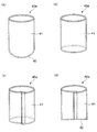
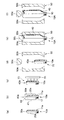
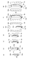
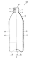
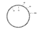
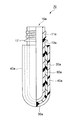
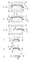
図1は、本発明の第1の実施の形態による複合容器を示す部分垂直断面図。FIG. 1 is a partial vertical sectional view showing a composite container according to a first embodiment of the present invention. 図2は、本発明の第1の実施の形態による複合容器を示す水平断面図(図1のII−II線断面図)。FIG. 2 is a horizontal sectional view showing the composite container according to the first embodiment of the present invention (sectional view taken along the line II-II in FIG. 1). 図3は、本発明の第1の実施の形態による複合プリフォームを示す部分垂直断面図。FIG. 3 is a partial vertical sectional view showing the composite preform according to the first embodiment of the present invention. 図4(a)〜(d)は、各種プラスチック製部材を示す斜視図。4A to 4D are perspective views showing various plastic members. 図5(a)〜(f)は、本発明の第1の実施の形態による複合容器の製造方法を示す概略図。FIGS. 5A to 5F are schematic views showing a method of manufacturing the composite container according to the first embodiment of the present invention. 図6(a)〜(f)は、本発明の第1の実施の形態の変形例による複合容器の製造方法を示す概略図。FIGS. 6A to 6F are schematic views showing a method for manufacturing a composite container according to a modification of the first embodiment of the present invention. 図7(a)〜(g)は、本発明の第1の実施の形態の変形例による複合容器の製造方法を示す概略図。FIGS. 7A to 7G are schematic views illustrating a method for manufacturing a composite container according to a modification of the first embodiment of the present invention. 図8は、本発明の第1の実施の形態による複合容器の変形例を示す部分垂直断面図。FIG. 8 is a partial vertical sectional view showing a modification of the composite container according to the first embodiment of the present invention. 図9は、本発明の第1の実施の形態による複合プリフォームの変形例を示す部分垂直断面図。FIG. 9 is a partial vertical sectional view showing a modification of the composite preform according to the first embodiment of the present invention. 図10は、本発明の第2の実施の形態による複合容器を示す部分垂直断面図。FIG. 10 is a partial vertical sectional view showing a composite container according to a second embodiment of the present invention. 図11は、本発明の第2の実施の形態による複合容器を示す水平断面図(図10のXI−XI線断面図)。FIG. 11 is a horizontal cross-sectional view (cross-sectional view taken along the line XI-XI in FIG. 10) showing the composite container according to the second embodiment of the present invention. 図12は、本発明の第2の実施の形態による複合プリフォームを示す部分垂直断面図。FIG. 12 is a partial vertical sectional view showing a composite preform according to the second embodiment of the present invention. 図13(a)〜(f)は、本発明の第2の実施の形態による複合容器の製造方法を示す概略図。FIGS. 13A to 13F are schematic views showing a method for manufacturing a composite container according to the second embodiment of the present invention. 図14(a)〜(f)は、本発明の第2の実施の形態の変形例による複合容器の製造方法を示す概略図。FIGS. 14A to 14F are schematic views showing a method for manufacturing a composite container according to a modification of the second embodiment of the present invention. 図15(a)〜(g)は、本発明の第2の実施の形態の変形例による複合容器の製造方法を示す概略図。FIGS. 15A to 15G are schematic views showing a method for manufacturing a composite container according to a modification of the second embodiment of the present invention. 図16は、本発明の第2の実施の形態による複合容器の変形例を示す部分垂直断面図。FIG. 16 is a partial vertical sectional view showing a modification of the composite container according to the second embodiment of the present invention. 図17は、本発明の第2の実施の形態による複合プリフォームの変形例を示す部分垂直断面図。FIG. 17 is a partial vertical sectional view showing a modification of the composite preform according to the second embodiment of the present invention.

第1の実施の形態
以下、図面を参照して本発明の第1の実施の形態について説明する。図1乃至図9は本発明の第1の実施の形態を示す図である。
First Embodiment Hereinafter, a first embodiment of the present invention will be described with reference to the drawings. 1 to 9 are views showing a first embodiment of the present invention.

まず、図1および図2により、本実施の形態による複合容器の製造方法(ブロー成形方法)によって作製される複合容器の概要について説明する。なお、本明細書中、「上」および「下」とは、それぞれ複合容器10Aを正立させた状態(図1)における上方および下方のことをいう。   First, an outline of a composite container produced by the composite container manufacturing method (blow molding method) according to the present embodiment will be described with reference to FIGS. 1 and 2. In the present specification, “upper” and “lower” refer to the upper side and the lower side in a state where the composite container 10A is erected (FIG. 1), respectively.

図1および図2に示す複合容器10Aは、後述するように、ブロー成形金型50を用いてプリフォーム10aおよびプラスチック製部材40aを含む複合プリフォーム70(図3参照)に対して2軸延伸ブロー成形を施すことにより、複合プリフォーム70のプリフォーム10aおよびプラスチック製部材40aを一体として膨張させて得られたものである。   A composite container 10A shown in FIGS. 1 and 2 is biaxially stretched with respect to a composite preform 70 (see FIG. 3) including a preform 10a and a plastic member 40a using a blow molding die 50, as will be described later. By performing blow molding, the preform 10a of the composite preform 70 and the plastic member 40a are integrally expanded.

このような複合容器10Aは、内側に位置するプラスチック材料製の容器本体10と、容器本体10の外側に密着して設けられたプラスチック製部材40とを備えている。   Such a composite container 10 </ b> A includes a container body 10 made of a plastic material located inside and a plastic member 40 provided in close contact with the outside of the container body 10.

このうち容器本体10は、口部11と、口部11下方に設けられた首部13と、首部13下方に設けられた肩部12と、肩部12下方に設けられた胴部20と、胴部20下方に設けられた底部30とを備えている。   Among these, the container body 10 includes a mouth portion 11, a neck portion 13 provided below the mouth portion 11, a shoulder portion 12 provided below the neck portion 13, a trunk portion 20 provided below the shoulder portion 12, And a bottom portion 30 provided below the portion 20.

他方、プラスチック製部材40は、容器本体10の外面に薄く延ばされた状態で密着されており、容器本体10に対して容易に移動又は回転しない状態で取付けられている。   On the other hand, the plastic member 40 is in close contact with the outer surface of the container main body 10 in a thinly extended state, and is attached to the container main body 10 without being easily moved or rotated.

次に容器本体10について詳述する。容器本体10は、上述したように口部11と、首部13と、肩部12と、胴部20と、底部30とを有している。   Next, the container body 10 will be described in detail. As described above, the container body 10 includes the mouth portion 11, the neck portion 13, the shoulder portion 12, the trunk portion 20, and the bottom portion 30.

このうち口部11は、図示しないキャップに螺着されるねじ部14と、ねじ部14下方に設けられたフランジ部17とを有している。なお、口部11の形状は、従来公知の形状であっても良い。   Of these, the mouth portion 11 includes a screw portion 14 screwed into a cap (not shown) and a flange portion 17 provided below the screw portion 14. The shape of the mouth portion 11 may be a conventionally known shape.

首部13は、フランジ部17と肩部12との間に位置しており、略均一な径をもつ略円筒形状を有している。また、肩部12は、首部13と胴部20との間に位置しており、首部13側から胴部20側に向けて徐々に径が拡大する形状を有している。   The neck portion 13 is located between the flange portion 17 and the shoulder portion 12 and has a substantially cylindrical shape having a substantially uniform diameter. The shoulder 12 is located between the neck 13 and the trunk 20 and has a shape whose diameter gradually increases from the neck 13 toward the trunk 20.

さらに、胴部20は、全体として略均一な径をもつ円筒形状を有している。しかしながら、これに限られるものではなく、胴部20が四角形筒形状や八角形筒形状等の多角形筒形状を有していても良い。あるいは、胴部20が上方から下方に向けて均一でない水平断面をもつ筒形状を有していても良い。また、本実施の形態において、胴部20は、凹凸が形成されておらず、略平坦な表面を有しているが、これに限られるものではない。例えば、胴部20にパネル又は溝等の凹凸が形成されていても良い。   Furthermore, the trunk | drum 20 has a cylindrical shape with a substantially uniform diameter as a whole. However, the present invention is not limited to this, and the body portion 20 may have a polygonal cylindrical shape such as a rectangular cylindrical shape or an octagonal cylindrical shape. Or the trunk | drum 20 may have a cylinder shape with a horizontal cross section which is not uniform toward upper direction from the downward direction. Moreover, in this Embodiment, although the unevenness | corrugation is not formed in the trunk | drum 20, and has a substantially flat surface, it is not restricted to this. For example, unevenness such as a panel or a groove may be formed on the body portion 20.

一方、底部30は、中央に位置する凹部31と、この凹部31周囲に設けられた接地部32とを有している。なお、底部30の形状についても特に限定されるものではなく、従来公知の底部形状(例えばペタロイド底形状や丸底形状等)を有していても良い。   On the other hand, the bottom portion 30 has a concave portion 31 located in the center and a grounding portion 32 provided around the concave portion 31. The shape of the bottom 30 is not particularly limited, and may have a conventionally known bottom shape (for example, a petaloid bottom shape or a round bottom shape).

また胴部20における容器本体10の厚みTは、これに限定されるものではないが、例えば満注容量が3L以上の大型のボトルの場合、300μm〜500μm(300μm以上500μm以下をいう。以下同様)程度に薄くすることができ、さらに、容器本体10の重量についても、これに限定されるものではないが、75g〜200gとすることができる。このように容器本体10の肉厚を薄くすることにより、容器本体10の軽量化を図ることができる。満注容量が3L未満の小型のボトルの場合、容器本体10の厚みTは、100μm〜200μm程度に薄くすることができ、さらに、容器本体10の重量についても、これに限定されるものではないが、10g〜20gとすることができる。このように容器本体10の肉厚を薄くすることにより、容器本体10の軽量化を図ることができる。 The thickness T 1 of the container body 10 in the barrel 20, but are not limited to, for example, the full delivery volume is not less than the large bottle 3L, refers to 300μm~500μm (300μm or 500μm or less. Hereinafter (Similarly), the weight of the container body 10 is not limited to this, but can be 75 g to 200 g. Thus, by reducing the thickness of the container main body 10, the weight of the container main body 10 can be reduced. In the case of a small bottle with a full capacity of less than 3 L, the thickness T 1 of the container body 10 can be reduced to about 100 μm to 200 μm, and the weight of the container body 10 is not limited to this. Although not, it can be 10g-20g. Thus, by reducing the thickness of the container main body 10, the weight of the container main body 10 can be reduced.

このような容器本体10は、合成樹脂材料を射出成形して製作したプリフォーム10a(後述)を二軸延伸ブロー成形することにより作製することができる。なおプリフォーム10a、すなわち容器本体10の材料としては熱可塑性樹脂、特にPE(ポリエチレン)、PP(ポリプロピレン)、PET(ポリエチレンテレフタレート)、PEN(ポリエチレンナフタレート)、PC(ポリカーボネート)を使用することが好ましい。容器本体10は、赤色、青色、黄色、緑色、茶色、黒色、白色等の色に着色されていても良いが、リサイクルのしやすさを考慮した場合、無色透明であることが好ましい。また、上述した各種樹脂をブレンドして用いても良い。さらに、容器本体10の内面に、容器のバリア性を高めるために、例えばダイヤモンド状炭素膜や酸化珪素薄膜等の蒸着膜を形成しても良い。   Such a container main body 10 can be manufactured by biaxially stretching blow-molding a preform 10a (described later) manufactured by injection molding a synthetic resin material. As the material of the preform 10a, that is, the container body 10, a thermoplastic resin, particularly PE (polyethylene), PP (polypropylene), PET (polyethylene terephthalate), PEN (polyethylene naphthalate), or PC (polycarbonate) may be used. preferable. The container body 10 may be colored in colors such as red, blue, yellow, green, brown, black, and white, but is preferably colorless and transparent in consideration of ease of recycling. Moreover, you may blend and use the various resin mentioned above. Further, a vapor deposition film such as a diamond-like carbon film or a silicon oxide thin film may be formed on the inner surface of the container body 10 in order to enhance the barrier property of the container.

また、容器本体10は、2層以上の多層成形ボトルとして形成することもできる。すなわち押し出し成形または射出成形により、例えば、中間層をMXD6、MXD6+脂肪酸塩、PGA(ポリグリコール酸)、EVOH(エチレンビニルアルコール共重合体)又はPEN(ポリエチレンナフタレート)等のガスバリア性及び遮光性を有する樹脂(中間層)として3層以上からなるプリフォーム10aを押出成形後、ブロー成形することによりガスバリア性及び遮光性を有する多層ボトルとして形成しても良い。なお、中間層としては、上述した各種樹脂をブレンドした樹脂を用いても良い。   The container body 10 can also be formed as a multilayer molded bottle having two or more layers. That is, by extrusion molding or injection molding, for example, the intermediate layer has gas barrier properties and light shielding properties such as MXD6, MXD6 + fatty acid salt, PGA (polyglycolic acid), EVOH (ethylene vinyl alcohol copolymer) or PEN (polyethylene naphthalate). You may form as a multilayer bottle which has gas barrier property and light-shielding property by extrusion-molding preform 10a which consists of three or more layers as resin which it has (intermediate layer), and carrying out blow molding. As the intermediate layer, a resin obtained by blending the above-described various resins may be used.

また、熱可塑性樹脂の溶融物に不活性ガス(窒素ガス、アルゴンガス)を混ぜることで、0.5〜100μmの発泡セル径を持つ発泡プリフォームを成形し、この発泡プリフォームをブロー成形することによって、容器本体10を作製しても良い。このような容器本体10は、発泡セルを内蔵しているため、容器本体10全体の遮光性を高めることができる。   Further, by mixing an inert gas (nitrogen gas, argon gas) with the thermoplastic resin melt, a foam preform having a foam cell diameter of 0.5 to 100 μm is formed, and this foam preform is blow-molded. Thus, the container body 10 may be manufactured. Since such a container main body 10 contains the foam cell, the light shielding property of the container main body 10 whole can be improved.

このような容器本体10は、大型のボトルの場合、満注容量が3000ml〜50000mlのボトルであることが好ましく、より好ましくは、満注容量が3000ml〜20000mlである。小型のボトルの場合、満注容量が100ml〜3000mlのボトルであることが好ましく、より好ましくは、満注容量が200ml〜2000mlである。   In the case of such a large-sized bottle, the container body 10 is preferably a bottle having a full capacity of 3000 ml to 50000 ml, and more preferably a full capacity of 3000 ml to 20000 ml. In the case of a small bottle, it is preferable that the full capacity is 100 ml to 3000 ml, and more preferably the full capacity is 200 ml to 2000 ml.

また、大型のボトルの場合、容器本体10のフランジ部17下方から接地部32までの高さHは、200mm〜1000mmとすることが好ましく、口部11の高さHは、例えば10mm〜100mmとすることが好ましい。また、容器本体10の胴部20における最大幅(最大径)Dは、75mm〜600mmとすることが好ましい。小型のボトルの場合、容器本体10のフランジ部17下方から接地部32までの高さHは、50mm〜200mmとすることが好ましく、口部11の高さHは、例えば7mm〜30mmとすることが好ましい。また、容器本体10の胴部20における最大幅(最大径)Dは、40mm〜100mmとすることが好ましい。 In the case of a large bottle, the height H 1 from the bottom of the flange portion 17 of the container body 10 to the grounding portion 32 is preferably 200 mm to 1000 mm, and the height H 2 of the mouth portion 11 is, for example, 10 mm to It is preferable to set it as 100 mm. Further, the maximum width (the maximum diameter) D 1 of the body portion 20 of the container body 10 is preferably in the 75Mm~600mm. In the case of a small bottle, the height H 1 from the bottom of the flange portion 17 of the container body 10 to the grounding portion 32 is preferably 50 mm to 200 mm, and the height H 2 of the mouth portion 11 is, for example, 7 mm to 30 mm. It is preferable to do. Further, the maximum width (the maximum diameter) D 1 of the body portion 20 of the container body 10 is preferably in the 40Mm~100mm.

次にプラスチック製部材40について説明する。プラスチック製部材40(40a)は後述するようにプリフォーム10aの外側を取り囲むように設けられ、プリフォーム10aの外側に密着された後、プリフォーム10aとともに2軸延伸ブロー成形されることにより得られたものである。このプラスチック製部材40は、後述するように、プラスチック製部材40aをプリフォーム10aとともに一体として延伸することにより作製されたものである。   Next, the plastic member 40 will be described. As will be described later, the plastic member 40 (40a) is provided so as to surround the outer side of the preform 10a. It is a thing. As will be described later, the plastic member 40 is produced by stretching a plastic member 40a together with the preform 10a.

プラスチック製部材40は容器本体10の外面に接着されることなく取付けられており、容器本体10に対して移動又は回転しないほどに密着されている。このプラスチック製部材40は、容器本体10の外面において薄く引き延ばされて容器本体10を覆っている。また、図2に示すように、プラスチック製部材40は、容器本体10を取り囲むようにその周方向全域にわたって設けられており、略円形状の水平断面を有している。   The plastic member 40 is attached to the outer surface of the container body 10 without being bonded, and is in close contact with the container body 10 so as not to move or rotate. The plastic member 40 is thinly extended on the outer surface of the container body 10 to cover the container body 10. As shown in FIG. 2, the plastic member 40 is provided over the entire circumferential direction so as to surround the container body 10, and has a substantially circular horizontal cross section.

この場合、プラスチック製部材40は、容器本体10のうち、口部11および首部13を除く、肩部12、胴部20および底部30を覆うように設けられている。これにより、容器本体10の肩部12、胴部20および底部30に対して所望の機能や特性を付与することができる。   In this case, the plastic member 40 is provided so as to cover the shoulder portion 12, the trunk portion 20, and the bottom portion 30 of the container body 10 except for the mouth portion 11 and the neck portion 13. Thereby, desired functions and characteristics can be imparted to the shoulder portion 12, the trunk portion 20, and the bottom portion 30 of the container body 10.

なお、プラスチック製部材40は、容器本体10のうち口部11以外の全域又は一部領域に設けられていても良い。例えば、プラスチック製部材40は、容器本体10のうち、口部11を除く、首部13、肩部12、胴部20および底部30の全体を覆うように設けられていても良い。さらに、プラスチック製部材40は1つに限らず、複数設けても良い。例えば、2つのプラスチック製部材40を肩部12の外面および底部30の外面にそれぞれ設けても良い。   The plastic member 40 may be provided in the entire region or a partial region other than the mouth portion 11 of the container body 10. For example, the plastic member 40 may be provided so as to cover the neck portion 13, the shoulder portion 12, the trunk portion 20, and the bottom portion 30 of the container body 10 except for the mouth portion 11. Further, the number of plastic members 40 is not limited to one, and a plurality of plastic members 40 may be provided. For example, you may provide the two plastic members 40 in the outer surface of the shoulder part 12, and the outer surface of the bottom part 30, respectively.

一方、プラスチック製部材40は、容器本体10に対して溶着ないし接着されていないため、容器本体10から剥離して除去することができる。具体的には、例えば刃物等を用いてプラスチック製部材40を切除したり、プラスチック製部材40に予め図示しない切断線を設け、この切断線に沿ってプラスチック製部材40を剥離したりすることができる。これにより、プラスチック製部材40を容器本体10から分離除去することができる。   On the other hand, since the plastic member 40 is not welded or bonded to the container body 10, it can be peeled off from the container body 10 and removed. Specifically, for example, the plastic member 40 may be cut using a blade or the like, or a cutting line (not shown) may be provided in advance on the plastic member 40, and the plastic member 40 may be peeled along the cutting line. it can. Thereby, the plastic member 40 can be separated and removed from the container body 10.

このようなプラスチック製部材40としては、プリフォーム10aに対して収縮する作用をもたないものであっても良く、収縮する作用をもつものであっても良い。   Such a plastic member 40 may have no contracting action on the preform 10a, or may have a contracting action.

またプラスチック製部材40の厚みTは、これに限定されるものではないが、容器本体10に取り付けられた状態で例えば100μm〜3000μm程度とすることができる。 The thickness T 2 of the plastic member 40 is not limited to, it can be a state of being attached to the container body 10, for example 100μm~3000μm about.

本実施の形態において、プラスチック製部材40は、赤色、青色、黄色、緑色、茶色、黒色、白色等の可視光色に着色されていても良い。また、プラスチック製部材40は、(半)透明であっても良く、不透明であっても良い。この場合、例えばプラスチック製部材40を可視光色に着色するとともに、容器本体10を無色透明にしても良い。あるいは、容器本体10およびプラスチック製部材40の両方を可視光色に着色しても良い。なお、可視光色に着色されたプラスチック製部材40を作製する場合、ブロー成形前のプラスチック製部材40aを射出成形等により作製する工程で、成形材料に可視光色の顔料を添加しても良い。   In the present embodiment, the plastic member 40 may be colored in a visible light color such as red, blue, yellow, green, brown, black, and white. The plastic member 40 may be (semi) transparent or opaque. In this case, for example, the plastic member 40 may be colored with visible light and the container body 10 may be colorless and transparent. Alternatively, both the container body 10 and the plastic member 40 may be colored in a visible light color. When producing the plastic member 40 colored in visible light color, a visible light color pigment may be added to the molding material in the step of producing the plastic member 40a before blow molding by injection molding or the like. .

次に図3により、本実施の形態による複合プリフォームの構成について説明する。   Next, the structure of the composite preform according to this embodiment will be described with reference to FIG.

図3に示すように、複合プリフォーム70は、プラスチック材料製のプリフォーム10aと、プリフォーム10aの外側に設けられた有底円筒状のプラスチック製部材40aとを備えている。   As shown in FIG. 3, the composite preform 70 includes a preform 10a made of a plastic material, and a bottomed cylindrical plastic member 40a provided outside the preform 10a.

プリフォーム10aは、口部11aと、口部11aに連結された胴部20aと、胴部20aに連結された底部30aとを備えている。このうち口部11aは、上述した容器本体10の口部11に対応するものであり、口部11と略同一の形状を有している。また、胴部20aは、上述した容器本体10の首部13、肩部12および胴部20に対応するものであり、略円筒形状を有している。底部30aは、上述した容器本体10の底部30に対応するものであり、略半球形状を有している。   The preform 10a includes a mouth portion 11a, a body portion 20a connected to the mouth portion 11a, and a bottom portion 30a connected to the body portion 20a. Of these, the mouth portion 11 a corresponds to the mouth portion 11 of the container body 10 described above, and has substantially the same shape as the mouth portion 11. Moreover, the trunk | drum 20a respond | corresponds to the neck part 13, the shoulder part 12, and the trunk | drum 20 of the container main body 10 mentioned above, and has a substantially cylindrical shape. The bottom 30a corresponds to the bottom 30 of the container body 10 described above, and has a substantially hemispherical shape.

本実施の形態において、大型のボトルの場合、胴部20aの直径dは、50mm〜200mmとなっており、50mm〜100mmとすることが好ましい。小型のボトルの場合、胴部20aの直径dは、25mm〜50mmとなっており、25mm〜35mmとすることが好ましい。なお、プリフォーム10aを射出成形により作製するとき、金型から抜き取りやすくする抜き勾配を設けるため、胴部20aは、口部11a側よりも底部30a側の胴径が若干細くなっていても良い。この場合、直径dは、胴部20aの最も太い箇所における直径によって規定する。ところで、大型のボトルの場合、従来一般的なプリフォームの胴部の径は、50mm〜100mm程度である。一方、本実施の形態によれば、胴部20aの直径dを100mm以上と太くしているので、後述するように、複合容器10Aをブロー成形により作製する工程において、容器本体10に対するプリフォーム10aの横方向延伸倍率を3.5倍以下とすることができる。小型のボトルの場合、従来一般的なプリフォームの胴部の径は、20mm〜25mm程度である。一方、本実施の形態によれば、胴部20aの直径dを25mm以上と太くしているので、後述するように、複合容器10Aをブロー成形により作製する工程において、容器本体10に対するプリフォーム10aの横方向延伸倍率を3.5倍以下とすることができる。これによりプラスチック製部材40aが広げられすぎて破断してしまう不具合を防止することができる。 In this embodiment, the case of a large bottle, the diameter d 1 of the body portion 20a is a 50 mm to 200 mm, it is preferable to 50 to 100 mm. For smaller bottles, diameter d 1 of the body portion 20a has a 25Mm~50mm, it is preferable to 25Mm~35mm. When the preform 10a is manufactured by injection molding, the body 20a may have a slightly smaller diameter on the bottom 30a side than the mouth 11a side in order to provide a draft angle that facilitates extraction from the mold. . In this case, the diameter d 1 is defined by the diameter of the thickest portion of the body portion 20a. By the way, in the case of a large-sized bottle, the diameter of the trunk part of a conventionally common preform is about 50 mm to 100 mm. On the other hand, according to this embodiment, since the diameter d 1 of the body portion 20a is thicker or more 100 mm, as will be described later, in a step of preparing a composite container 10A by blow molding, the preform for the container body 10 The transverse stretch ratio of 10a can be 3.5 times or less. In the case of a small bottle, the diameter of the body portion of a conventional preform is about 20 mm to 25 mm. On the other hand, according to this embodiment, since the diameter d 1 of the body portion 20a is thicker or more 25 mm, as will be described later, in a step of preparing a composite container 10A by blow molding, the preform for the container body 10 The transverse stretch ratio of 10a can be 3.5 times or less. As a result, it is possible to prevent a problem that the plastic member 40a is too widened and broken.

また、プリフォーム10aのフランジ部17下方から底部30aの最下点までの高さhは、大型のボトルの場合、200mm〜1000mmとすることが好ましく、200mm〜600mmとすることが更に好ましい。小型のボトルの場合、50mm〜200mmとすることが好ましく、100mm〜200mmとすることが更に好ましい。高さhをこの範囲にすることにより、縦方向延伸を抑えることが可能であり、成形しやすくなる。プリフォーム10aの口部11aの高さhは、上述した容器本体10の口部11の高さHと略同一であり、例えば大型のボトルの場合、10mm〜100mmであり、小型のボトルの場合、7mm〜30mmである。 In addition, in the case of a large bottle, the height h 1 from the lower portion of the flange portion 17 of the preform 10a to the lowest point of the bottom portion 30a is preferably 200 mm to 1000 mm, and more preferably 200 mm to 600 mm. In the case of a small bottle, it is preferably 50 mm to 200 mm, and more preferably 100 mm to 200 mm. The height h 1 By this range, it is possible to suppress the longitudinal stretching, it is easy to mold. The height h 2 of the mouth portion 11a of the preform 10a is substantially identical to the height H 2 of the mouth 11 of the container body 10 described above, for example, in the case of a large bottle, a 10 mm to 100 mm, small bottles In this case, it is 7 mm to 30 mm.

さらに、胴部20aにおけるプリフォーム10aの最大厚みtは、大型のボトルの場合、4mm〜10mmとすることが好ましく、6mm〜8mmとすることが更に好ましい。厚みtを4mm以上とすることにより、容器本体10の肉厚調整を容易にすることができる。また厚みtを10mm以下とすることにより、容器本体10に対するプリフォーム10aの横方向延伸倍率を3.5倍以下とした場合であっても、容器本体10の厚みTが厚くなりすぎることを防止することができる。小型のボトルの場合、2mm〜5mmとすることが好ましく、3mm〜4.5mmとすることが更に好ましい。厚みtを3mm以上とすることにより、容器本体10の肉厚調整を容易にすることができる。また厚みtを5mm以下とすることにより、容器本体10に対するプリフォーム10aの横方向延伸倍率を3.5倍以下とした場合であっても、容器本体10の厚みTが厚くなりすぎることを防止することができる。 Furthermore, the maximum thickness t 1 of the preform 10a in the body portion 20a in the case of a large bottle, preferably to 4 mm to 10 mm, and more preferably be 6Mm~8mm. By the thickness t 1 or more 4 mm, it is possible to facilitate the thickness adjustment of the container body 10. Further, by setting the thickness t 1 to 10 mm or less, the thickness T 1 of the container body 10 becomes too thick even when the transverse stretching ratio of the preform 10a with respect to the container body 10 is 3.5 times or less. Can be prevented. In the case of a small bottle, it is preferably 2 mm to 5 mm, and more preferably 3 mm to 4.5 mm. By the thickness t 1 or more 3 mm, it is possible to facilitate the thickness adjustment of the container body 10. Further, by setting the thickness t 1 to 5 mm or less, the thickness T 1 of the container body 10 becomes too thick even when the transverse stretching ratio of the preform 10a with respect to the container body 10 is 3.5 times or less. Can be prevented.

プラスチック製部材40aは、プリフォーム10aの外面に接着されることなく取付けられており、プリフォーム10aに対して移動又は回転しないほどに密着されているか、又は自重で落下しない程度に密着されている。プラスチック製部材40aは、プリフォーム10aを取り囲むようにその周方向全域にわたって設けられており、円形状の水平断面を有している。   The plastic member 40a is attached to the outer surface of the preform 10a without being bonded, and is in close contact with the preform 10a so as not to move or rotate, or in close contact with the preform 10a so as not to fall by its own weight. . The plastic member 40a is provided over the entire circumferential direction so as to surround the preform 10a, and has a circular horizontal cross section.

プラスチック製部材40aの厚みtは、例えば100μm〜3000μm程度とすることができる。厚みtを100mm以上とすることにより、ブロー成形時にプラスチック製部材40aが引き延ばされて破断してしまう不具合が防止される。また厚みtを3000mm以下とすることにより、ブロー成形時にプラスチック製部材40aが十分に引き延ばされなくなる不具合が防止される。 The thickness t 2 of the plastic member 40a may be, for example 100μm~3000μm about. By setting the thickness t 2 or more 100 mm, inconvenience of plastic member 40a will be broken stretched is prevented during blow molding. Further, by setting the thickness t 2 less 3000 mm, the plastic member 40a is not stretched sufficiently defect is prevented at the time of blow molding.

この場合、プラスチック製部材40aは、胴部20aのうち容器本体10の首部13に対応する部分13aを除く全域と、底部30aの全域とを覆うように設けられている。また、プラスチック製部材40aは、赤色、青色、黄色、緑色、茶色、黒色、白色等の可視光色に着色されていても良い。   In this case, the plastic member 40a is provided so as to cover the entire region of the body portion 20a excluding the portion 13a corresponding to the neck portion 13 of the container body 10 and the entire region of the bottom portion 30a. Moreover, the plastic member 40a may be colored in visible light colors such as red, blue, yellow, green, brown, black, and white.

なお、プラスチック製部材40aは、口部11a以外の全域又は一部領域に設けられていても良い。例えば、プラスチック製部材40aは、口部11aを除く、胴部20aおよび底部30aの全体を覆うように設けられていても良い。さらに、プラスチック製部材40aは1つに限らず、複数設けても良い。例えば、2つのプラスチック製部材40aを胴部20aの外側2箇所にそれぞれ設けても良い。   The plastic member 40a may be provided in the entire region or a partial region other than the mouth portion 11a. For example, the plastic member 40a may be provided so as to cover the entire body portion 20a and the bottom portion 30a except for the mouth portion 11a. Furthermore, the number of plastic members 40a is not limited to one, and a plurality of plastic members 40a may be provided. For example, two plastic members 40a may be provided at two locations outside the trunk portion 20a.

このようなプラスチック製部材40aとしては、プリフォーム10aに対して収縮する作用をもたないものであっても良く、収縮する作用をもつものであっても良い。   Such a plastic member 40a may be one that does not have a contracting action on the preform 10a or may have a contracting action.

前者の場合、プラスチック製部材40aとしては、例えばダイレクトブロー成形法によって作製されたダイレクトブロー成形チューブ、シート成形法によって作製されたシート成形チューブ、押出成形により作製された押出チューブ、インフレーション成形により作製されたインフレーション成形チューブ等を用いることができるが、これに限定されるものではなく、上記以外の成形方法を用いても良い。   In the former case, the plastic member 40a is produced by, for example, a direct blow molded tube produced by a direct blow molding method, a sheet molded tube produced by a sheet molding method, an extruded tube produced by extrusion molding, or inflation molding. However, the present invention is not limited to this, and other molding methods may be used.

後者の場合、すなわちプラスチック製部材(外側収縮部材)40aが収縮する作用をもつ場合、プラスチック製部材(外側収縮部材)40aは、例えば、外的な作用(例えば熱)が加えられた際、プリフォーム10aに対して収縮(例えば熱収縮)するものが用いられても良い。あるいは、プラスチック製部材(外側収縮部材)40aは、それ自体が収縮性ないし弾力性を持ち、外的な作用を加えることなく収縮可能なものであっても良い。   In the latter case, that is, when the plastic member (outer contraction member) 40a has an action of contracting, the plastic member (outer contraction member) 40a is, for example, when an external action (for example, heat) is applied. What shrinks | contracts with respect to the reform 10a (for example, heat shrink) may be used. Alternatively, the plastic member (outer contraction member) 40a itself may be contractible or elastic and can contract without applying an external action.

プラスチック製部材40aとしては、例えば、ポリエチレン、ポリプロピレン、ポリエチレンテレフタレート、ポリエチレンナフタレート、ポリ−4−メチルペンテン−1、ポリスチレン、AS樹脂、ABS樹旨、ポリ塩化ビニル、ポリ塩化ビニリデン、ポリ酢酸ビニル、ポリビニルアルコール、ポリビニルアセタール、ポリビニルブチラール、フタル酸ジアリル樹脂、フッ素系樹脂、ポリメタクリル酸メチル、ポリアクリル酸、ポリアクリル酸メチル、ポリアクリロニトリル、ポリアクリルアミド、ポリブタジエン、ポリブテン−1、ポリイソプレン、ポリクロロプレン、エチレンプロピレンゴム、ブチルゴム、ニトリルゴム、アクリルゴム、シリコーンゴム、フッ素ゴム、ナイロン6、ナイロン6,6、ナイロンMXD6、芳香族ポリアミド、ポリカーボネート、ポリテレフタル酸エチレン、ポリテレフタル酸ブチレン、ポリナフタレン酸エチレン、Uポリマー、液晶ポリマー、変性ポリフェニレンエーテル、ポリエーテルケトン、ポリエーテルエーテルケトン、不飽和ポリエステル、アルキド樹脂、ポリイミド、ポリスルホン、ポリフェニレンスルフィド、ポリエーテルスルホン、シリコーン樹脂、ポリウレタン、フェノール樹脂、尿素樹脂、ポリエチレンオキシド、ポリプロピレンオキシド、ポリアセタール、エポキシ樹脂等を挙げることができる。このうちポリエチレン(PE)、ポリプロピレン(PP)、ポリエチレンテレフタレート(PET)、ポリエチレンナフタレート(PEN)等の熱可塑性非弾性樹脂を用いることが好ましい。またそれらのブレンド材料や多層構造、部分的多層構造のものであってもよい。さらに、プラスチック製部材40aの材料には、その特性が損なわれない範囲において、主成分の樹脂以外にも、各種の添加剤を添加してもよい。添加剤としては、例えば、可塑剤、紫外線安定化剤、着色防止剤、艶消し剤、消臭剤、難燃剤、耐候剤、帯電防止剤、糸摩擦低減剤、スリップ剤、離型剤、抗酸化剤、イオン交換剤、および着色顔料等を添加することができる。また、熱可塑性樹脂の溶融物に不活性ガス(窒素ガス、アルゴンガス)を混ぜることで、0.5〜100μmの発泡セル径を持つ発泡部材を使用し、この発泡プリフォームを成形することによって、遮光性を高めることができる。   Examples of the plastic member 40a include polyethylene, polypropylene, polyethylene terephthalate, polyethylene naphthalate, poly-4-methylpentene-1, polystyrene, AS resin, ABS tree, polyvinyl chloride, polyvinylidene chloride, polyvinyl acetate, Polyvinyl alcohol, polyvinyl acetal, polyvinyl butyral, diallyl phthalate resin, fluororesin, polymethyl methacrylate, polyacrylic acid, polymethyl acrylate, polyacrylonitrile, polyacrylamide, polybutadiene, polybutene-1, polyisoprene, polychloroprene, Ethylene propylene rubber, butyl rubber, nitrile rubber, acrylic rubber, silicone rubber, fluoro rubber, nylon 6, nylon 6,6, nylon MXD6, aromatic poly , Polycarbonate, ethylene polyterephthalate, polybutylene terephthalate, poly ethylene naphthalate, U polymer, liquid crystal polymer, modified polyphenylene ether, polyether ketone, polyether ether ketone, unsaturated polyester, alkyd resin, polyimide, polysulfone, polyphenylene Examples thereof include sulfide, polyethersulfone, silicone resin, polyurethane, phenol resin, urea resin, polyethylene oxide, polypropylene oxide, polyacetal, and epoxy resin. Among these, it is preferable to use thermoplastic inelastic resins such as polyethylene (PE), polypropylene (PP), polyethylene terephthalate (PET), and polyethylene naphthalate (PEN). Moreover, those blend materials, multilayer structures, and partial multilayer structures may be used. Furthermore, various additives other than the main component resin may be added to the material of the plastic member 40a as long as the characteristics are not impaired. Examples of additives include plasticizers, UV stabilizers, anti-coloring agents, matting agents, deodorants, flame retardants, weathering agents, antistatic agents, yarn friction reducing agents, slip agents, mold release agents, An oxidizing agent, an ion exchange agent, a coloring pigment, and the like can be added. Also, by mixing an inert gas (nitrogen gas, argon gas) with a melt of a thermoplastic resin, a foam member having a foam cell diameter of 0.5 to 100 μm is used, and this foam preform is molded. , The light shielding property can be improved.

またプラスチック製部材40aが容器本体10(プリフォーム10a)と同一の材料からなっていても良い。この場合、複合容器10Aのうち、例えば強度を高めたい部分に重点的にプラスチック製部材40を配置し、当該箇所の強度を選択的に高めることができる。例えば、容器本体10の肩部12周辺および底部30周辺にプラスチック製部材40を設け、この部分の強度を高めても良い。このような材料としては、熱可塑性樹脂、特にPE(ポリエチレン)、PP(ポリプロピレン)、PET(ポリエチレンテレフタレート)、PEN(ポリエチレンナフタレート)、PC(ポリカーボネート)を挙げることができる。   The plastic member 40a may be made of the same material as the container body 10 (preform 10a). In this case, in the composite container 10A, for example, the plastic member 40 can be intensively arranged at a portion where the strength is to be increased, and the strength of the portion can be selectively increased. For example, plastic members 40 may be provided around the shoulder 12 and the bottom 30 of the container body 10 to increase the strength of this portion. Examples of such materials include thermoplastic resins, particularly PE (polyethylene), PP (polypropylene), PET (polyethylene terephthalate), PEN (polyethylene naphthalate), and PC (polycarbonate).

またプラスチック製部材40aは、酸素バリア性又は水蒸気バリア性等のガスバリア性を有する材料からなっていても良い。この場合、プリフォーム10aとして多層プリフォームやブレンド材料を含むプリフォーム等を用いることなく、複合容器10Aのガスバリア性を高め、酸素や水蒸気によって内容液が劣化することを防止することができる。例えば、容器本体10のうち、肩部12、首部13、胴部20および底部30の全域にプラスチック製部材40を設け、この部分のガスバリア性を高めても良い。このような材料としては、PE(ポリエチレン)、PP(ポリプロピレン)、MXD−6(ナイロン)、PGA(ポリグリコール酸)、EVOH(エチレンビニルアルコール共重合体)またはこれらの材料に脂肪酸塩などの酸素吸収材を混ぜることも考えられる。   The plastic member 40a may be made of a material having a gas barrier property such as an oxygen barrier property or a water vapor barrier property. In this case, the gas barrier property of the composite container 10A can be enhanced without using a multilayer preform or a preform containing a blend material as the preform 10a, and the content liquid can be prevented from being deteriorated by oxygen or water vapor. For example, a plastic member 40 may be provided in the entire region of the shoulder portion 12, the neck portion 13, the trunk portion 20, and the bottom portion 30 of the container body 10, and the gas barrier property of this portion may be improved. Examples of such materials include PE (polyethylene), PP (polypropylene), MXD-6 (nylon), PGA (polyglycolic acid), EVOH (ethylene vinyl alcohol copolymer), and oxygen such as fatty acid salts in these materials. It is also possible to mix an absorbent material.

またプラスチック製部材40aは、紫外線等の光線バリア性を有する材料からなっていても良い。この場合、プリフォーム10aとして多層プリフォームやブレンド材料を含むプリフォーム等を用いることなく、複合容器10Aの光線バリア性を高め、紫外線等により内容液が劣化することを防止することができる。例えば、容器本体10のうち、肩部12、首部13、胴部20および底部30の全域にプラスチック製部材40aを設け、この部分の紫外線バリア性を高めても良い。このような材料としては、ブレンド材料、またはPETやPE、PPに遮光性樹脂を添加した材料が考えられる。また、熱可塑性樹脂の溶融物に不活性ガス(窒素ガス、アルゴンガス)を混ぜることにより作製された、0.5〜100μmの発泡セル径を持つ発泡部材を使用しても良い。   The plastic member 40a may be made of a material having a light barrier property such as ultraviolet rays. In this case, the light barrier property of the composite container 10A can be improved and the content liquid can be prevented from being deteriorated by ultraviolet rays or the like without using a multilayer preform or a preform containing a blend material as the preform 10a. For example, a plastic member 40a may be provided in the entire region of the shoulder portion 12, the neck portion 13, the trunk portion 20, and the bottom portion 30 of the container body 10 to enhance the ultraviolet barrier property of this portion. As such a material, a blend material or a material obtained by adding a light-shielding resin to PET, PE, or PP can be considered. Moreover, you may use the foaming member with the foam cell diameter of 0.5-100 micrometers produced by mixing inert gas (nitrogen gas, argon gas) with the melt of a thermoplastic resin.

またプラスチック製部材40aは、容器本体10(プリフォーム10a)を構成するプラスチック材料よりも保冷性又は保温性の高い材料(熱伝導性の低い材料)からなっていても良い。この場合、容器本体10そのものの厚みを厚くすることなく、内容液の温度が複合容器10Aの表面まで伝達しにくくすることが可能となる。これにより、複合容器10Aの保冷性又は保温性が高められる。例えば、容器本体10のうち胴部20の全部又は一部にプラスチック製部材40を設け、胴部20の保冷性又は保温性を高めても良い。また、使用者が複合容器10Aを把持した際、冷たすぎたり熱すぎたりすることにより複合容器10Aを持ちにくくなることが防止される。このような材料としては、発泡化したポリウレタン、ポリスチレン、PE(ポリエチレン)、PP(ポリプロピレン)、フェノール樹脂、ポリ塩化ビニル、ユリア樹脂、シリコーン、ポリイミド、メラミン樹脂などが考えられる。これら樹脂を含んでなる樹脂材料に、中空粒子を混合することが好ましい。中空粒子の平均粒子径は、1〜200μmであることが好ましく、5〜80μmであることがより好ましい。なお、「平均粒子径」とは、体積平均粒子径を意味し、粒度分布・粒径分布測定装置(例えば、ナノトラック粒度分布測定装置、日機装株式会社製など)を用いて公知の方法により測定することができる。また、中空粒子としては、樹脂などから構成される有機系中空粒子であってもよく、ガラスなどから構成される無機系中空粒子であってもよいが、分散性が優れるという理由から、有機系中空粒子が好ましい。有機系中空粒子を構成する樹脂としては、例えば、架橋スチレン−アクリル樹脂などのスチレン系樹脂、アクリロニトリル−アクリル樹脂などの(メタ)アクリル系樹脂、フェノール系樹脂、フッ素系樹脂、ポリアミド系樹脂、ポリイミド系樹脂、ポリカーボネート系樹脂、ポリエーテル系樹脂などを挙げることができる。また、ローペイクHP−1055、ローペイクHP−91、ローペイクOP−84J、ローペイクウルトラ、ローペイクSE、ローペイクST(ロームアンドハース(株)製)、ニポールMH−5055(日本ゼオン(株)製)、SX8782、SX866(JSR(株)製)などの市販される中空粒子を用いることも出来る。中空粒子の含有量としては、プラスチック製部材40aに含有される樹脂材料100質量部に対して、0.01〜50質量部であることが好ましく、1〜20質量部であることがより好ましい。   In addition, the plastic member 40a may be made of a material having a higher cold-retaining property or higher heat-retaining property (a material having a lower thermal conductivity) than the plastic material constituting the container body 10 (preform 10a). In this case, it is possible to make it difficult for the temperature of the content liquid to be transmitted to the surface of the composite container 10A without increasing the thickness of the container body 10 itself. Thereby, the cold insulation property or heat retention property of composite container 10A is improved. For example, the plastic member 40 may be provided on the whole or a part of the body 20 in the container body 10 to enhance the cold insulation or heat insulation of the body 20. Further, when the user grips the composite container 10A, it is prevented that the composite container 10A becomes difficult to hold due to being too cold or too hot. Examples of such materials include foamed polyurethane, polystyrene, PE (polyethylene), PP (polypropylene), phenol resin, polyvinyl chloride, urea resin, silicone, polyimide, melamine resin, and the like. It is preferable to mix hollow particles with a resin material containing these resins. The average particle diameter of the hollow particles is preferably 1 to 200 μm, and more preferably 5 to 80 μm. The “average particle size” means the volume average particle size and is measured by a known method using a particle size distribution / particle size distribution measuring device (for example, Nanotrack particle size distribution measuring device, manufactured by Nikkiso Co., Ltd.). can do. The hollow particles may be organic hollow particles composed of a resin or the like, or may be inorganic hollow particles composed of glass or the like. Hollow particles are preferred. Examples of the resin constituting the organic hollow particles include styrene resins such as cross-linked styrene-acrylic resins, (meth) acrylic resins such as acrylonitrile-acrylic resins, phenolic resins, fluorine resins, polyamide resins, and polyimides. Resin, polycarbonate resin, polyether resin and the like. In addition, Ropeke HP-1055, Ropeke HP-91, Ropeke OP-84J, Ropeke Ultra, Ropeke SE, Ropeke ST (made by Rohm and Haas Co.), Nipol MH-5055 (made by Nippon Zeon Co., Ltd.), SX8782 Commercially available hollow particles such as SX866 (manufactured by JSR Corporation) can also be used. As content of a hollow particle, it is preferable that it is 0.01-50 mass parts with respect to 100 mass parts of resin materials contained in the plastic members 40a, and it is more preferable that it is 1-20 mass parts.

またプラスチック製部材40aは、容器本体10(プリフォーム10a)を構成するプラスチック材料よりも滑りにくい材料からなっていても良い。この場合、容器本体10の材料を変更することなく、使用者が複合容器10Aを把持しやすくすることができる。例えば、容器本体10のうち胴部20の全部又は一部にプラスチック製部材40を設け、胴部20を持ちやすくしても良い。   The plastic member 40a may be made of a material that is less slippery than the plastic material that constitutes the container body 10 (preform 10a). In this case, the user can easily hold the composite container 10 </ b> A without changing the material of the container body 10. For example, a plastic member 40 may be provided on all or part of the body 20 of the container body 10 so that the body 20 can be easily held.

このプラスチック製部材40aには、予めデザイン又は印字等の印刷が施されていても良い。この場合、印刷は例えばインクジェット法やグラビア印刷法等の印刷法により、無地のプラスチック製部材40aにデザイン又は印字が施されて形成されても良い。この印刷は、プリフォーム10aに取り付けられる前のプラスチック製部材40aに対して施されても良く、プリフォーム10aの外側にプラスチック製部材40aを設けた状態で施されても良い。また、プラスチック製部材40aは、赤色、青色、黄色、緑色、茶色、黒色、白色等の色に着色されていても良く、また透明であっても不透明であっても良い。   The plastic member 40a may be preliminarily printed with design or printing. In this case, the printing may be formed by designing or printing the plain plastic member 40a by a printing method such as an inkjet method or a gravure printing method. This printing may be performed on the plastic member 40a before being attached to the preform 10a, or may be performed in a state where the plastic member 40a is provided outside the preform 10a. The plastic member 40a may be colored in colors such as red, blue, yellow, green, brown, black, and white, and may be transparent or opaque.

次にプラスチック製部材40aの形状について説明する。   Next, the shape of the plastic member 40a will be described.

図3および図4(a)に示すように、プラスチック製部材40aは、全体として有底円筒形状からなり、円筒状の胴部41と、胴部41に連結された底部42とを有していても良い。この場合、プラスチック製部材40aの底部42がプリフォーム10aの底部30aを覆うので、複合容器10Aの胴部20に加え、底部30に対しても波長400nm〜500nmの光線に対するバリア性等の様々な機能や特性を付与することができる。このようなプラスチック製部材40aは、例えば上述したブローチューブやシート成形チューブを挙げることができる。   As shown in FIGS. 3 and 4A, the plastic member 40a has a bottomed cylindrical shape as a whole, and includes a cylindrical body 41 and a bottom 42 connected to the body 41. May be. In this case, since the bottom part 42 of the plastic member 40a covers the bottom part 30a of the preform 10a, in addition to the trunk part 20 of the composite container 10A, the bottom part 30 also has various barrier properties such as a barrier property against light having a wavelength of 400 nm to 500 nm. Functions and properties can be added. Examples of such a plastic member 40a include the above-described blow tube and sheet molded tube.

また、図9(後述)および図4(b)に示すように、プラスチック製部材40aは、全体として円管形状(無底円筒形状)からなり、円筒状の胴部41を有していても良い。この場合、プラスチック製部材40aとしては、例えば上述したブローチューブ、押出チューブ、インフレーション成形チューブ、シート成形チューブを用いることができる。   Further, as shown in FIGS. 9 (described later) and FIG. 4B, the plastic member 40a has a circular tube shape (bottomless cylindrical shape) as a whole, and has a cylindrical body 41. good. In this case, as the plastic member 40a, for example, the above-described blow tube, extruded tube, inflation molded tube, or sheet molded tube can be used.

また、図4(c)および図4(d)に示すように、プラスチック製部材40aは、フィルムを筒状に形成してその端部を貼り合わせることにより作製されても良い。この場合、図4(c)に示すように、プラスチック製部材40aは、胴部41を有する管形状(無底円筒形状)に構成されていても良く、図4(d)に示すように、底部42を貼り合わせることにより有底筒形状に構成されていても良い。   Moreover, as shown in FIG.4 (c) and FIG.4 (d), the plastic members 40a may be produced by forming a film in a cylinder shape and bonding the edge part together. In this case, as shown in FIG. 4 (c), the plastic member 40a may be configured in a tubular shape (bottomless cylindrical shape) having a body portion 41, and as shown in FIG. 4 (d), The bottom 42 may be bonded to form a bottomed cylinder.

次に図5(a)〜(f)により、本実施の形態による複合容器10Aの製造方法(ブロー成形方法)について説明する。   Next, a manufacturing method (blow molding method) of the composite container 10A according to the present embodiment will be described with reference to FIGS.

まず、プラスチック材料製のプリフォーム10aを準備する(図5(a)参照)。この場合、例えば図示しない射出成形機を用いて、射出成形法によりプリフォーム10aを作製しても良い。このプリフォーム10aは、口部11aと、直径dが25mm〜200mmの胴部20aと、略半球形状の底部30aとを有している。 First, a preform 10a made of a plastic material is prepared (see FIG. 5A). In this case, for example, the preform 10a may be manufactured by an injection molding method using an unillustrated injection molding machine. The preform 10a has a mouth portion 11a, a barrel portion 20a having a diameter d 1 is 25Mm~200mm, a bottom 30a of a substantially hemispherical shape.

次に、プラスチック製部材40aを準備する。この場合、プラスチック製部材40aは、全体として有底円筒形状からなり、円筒状の胴部41と、胴部41に連結された底部42とを有している。   Next, the plastic member 40a is prepared. In this case, the plastic member 40 a has a bottomed cylindrical shape as a whole, and includes a cylindrical body portion 41 and a bottom portion 42 connected to the body portion 41.

次に、プリフォーム10aの外側にプラスチック製部材40aを設けることにより、プリフォーム10aと、プリフォーム10aの外側に密着されたプラスチック製部材40aとを有する複合プリフォーム70を作製する(図5(b)参照)。   Next, by providing a plastic member 40a on the outside of the preform 10a, a composite preform 70 having the preform 10a and the plastic member 40a in close contact with the outside of the preform 10a is manufactured (FIG. 5 ( b)).

この場合、プリフォーム10aの外径と同一又はわずかに小さい内径をもつプラスチック製部材40aを、プリフォーム10aに対して押し込むことにより、プリフォーム10aの外面に密着させても良い。あるいは、後述するように、熱収縮性をもつプラスチック製部材40aをプリフォーム10aの外面に設け、このプラスチック製部材40aを50℃乃至100℃に加熱することにより熱収縮させてプリフォーム10aの外面に密着させても良い。   In this case, a plastic member 40a having an inner diameter that is the same as or slightly smaller than the outer diameter of the preform 10a may be pressed into the preform 10a to be brought into close contact with the outer surface of the preform 10a. Alternatively, as will be described later, a heat-shrinkable plastic member 40a is provided on the outer surface of the preform 10a, and the plastic member 40a is thermally contracted by heating to 50 ° C. to 100 ° C. You may make it stick to.

このように、予めプリフォーム10aの外側にプラスチック製部材40aを密着させ、複合プリフォーム70を作製しておくことにより、複合プリフォーム70を作製する一連の工程(図5(a)〜(b))と、複合容器10Aをブロー成形により作製する一連の工程(図5(c)〜(f))とを別々の場所(工場等)で実施することが可能になる。   In this way, a series of steps for producing the composite preform 70 (FIGS. 5A to 5B) are performed by previously bringing the plastic member 40a into close contact with the outside of the preform 10a and producing the composite preform 70. )) And a series of steps (FIGS. 5 (c) to 5 (f)) for producing the composite container 10A by blow molding can be performed at different places (factories, etc.).

次に、複合プリフォーム70は、加熱装置51によって加熱される(図5(c)参照)。このとき、複合プリフォーム70は、口部11aを下に向けた状態で回転しながら、加熱装置51によって周方向に均等に加熱される。この加熱工程におけるプリフォーム10aおよびプラスチック製部材40aの加熱温度は、例えば90℃乃至130℃としても良い。   Next, the composite preform 70 is heated by the heating device 51 (see FIG. 5C). At this time, the composite preform 70 is evenly heated in the circumferential direction by the heating device 51 while rotating with the mouth portion 11a facing downward. The heating temperature of the preform 10a and the plastic member 40a in this heating step may be, for example, 90 ° C. to 130 ° C.

続いて、加熱装置51によって加熱された複合プリフォーム70は、ブロー成形金型50に送られる(図5(d)参照)。   Subsequently, the composite preform 70 heated by the heating device 51 is sent to the blow molding die 50 (see FIG. 5D).

複合容器10Aは、このブロー成形金型50を用いて成形される。この場合、ブロー成形金型50は互いに分割された一対の胴部金型50a、50bと、底部金型50cとからなる(図5(d)参照)。図5(d)において、一対の胴部金型50a、50b間は互いに開いており、底部金型50cは上方に上がっている。この状態で一対の胴部金型50a、50b間に、複合プリフォーム70が挿入される。   The composite container 10 </ b> A is molded using this blow molding die 50. In this case, the blow mold 50 is composed of a pair of body molds 50a and 50b and a bottom mold 50c which are divided from each other (see FIG. 5D). In FIG. 5 (d), the pair of body molds 50a and 50b are open to each other, and the bottom mold 50c is raised upward. In this state, the composite preform 70 is inserted between the pair of body molds 50a and 50b.

次に図5(e)に示すように、底部金型50cが下がったのちに一対の胴部金型50a、50bが閉鎖され、一対の胴部金型50a、50bおよび底部金型50cにより密閉されたブロー成形金型50が構成される。   Next, as shown in FIG. 5E, after the bottom mold 50c is lowered, the pair of body molds 50a, 50b is closed, and sealed by the pair of body molds 50a, 50b and the bottom mold 50c. A blow mold 50 is formed.

次にプリフォーム10a内に空気が圧入され、複合プリフォーム70に対して2軸延伸ブロー成形が施される。   Next, air is press-fitted into the preform 10 a and biaxial stretch blow molding is performed on the composite preform 70.

このことにより、ブロー成形金型50内でプリフォーム10aから容器本体10が得られる。この間、胴部金型50a、50bは30℃乃至80℃まで加熱され、底部金型50cは5℃乃至25℃まで冷却される。この際、ブロー成形金型50内では、複合プリフォーム70のプリフォーム10aおよびプラスチック製部材40aが一体として膨張される。これにより、プリフォーム10aおよびプラスチック製部材40aは、一体となってブロー成形金型50の内面に対応する形状に賦形される。   As a result, the container body 10 is obtained from the preform 10 a in the blow molding die 50. During this time, the body molds 50a and 50b are heated to 30 ° C. to 80 ° C., and the bottom mold 50c is cooled to 5 ° C. to 25 ° C. At this time, in the blow mold 50, the preform 10a of the composite preform 70 and the plastic member 40a are expanded as a unit. Thereby, the preform 10a and the plastic member 40a are integrally formed into a shape corresponding to the inner surface of the blow mold 50.

このようにして、容器本体10と、容器本体10の外面に設けられたプラスチック製部材40とを備えた複合容器10Aが得られる。   In this manner, a composite container 10A including the container body 10 and the plastic member 40 provided on the outer surface of the container body 10 is obtained.

このブロー成形の際、容器本体10に対するプリフォーム10aの横方向延伸倍率は3.5倍以下となっており、好ましくは3倍以下となっている。このように、ブロー成形時の横方向延伸倍率を3.5倍以下に抑えたことにより、プラスチック製部材40aが引き延ばされて破断してしまう不具合を防止することができる。一方、容器本体10に対するプリフォーム10aの縦方向延伸倍率は、好ましくは3倍以下となっている。   In this blow molding, the transverse stretching ratio of the preform 10a with respect to the container body 10 is 3.5 times or less, preferably 3 times or less. As described above, by suppressing the transverse stretching ratio at the time of blow molding to 3.5 times or less, it is possible to prevent a problem that the plastic member 40a is stretched and broken. On the other hand, the longitudinal stretch ratio of the preform 10a with respect to the container body 10 is preferably 3 times or less.

次に図5(f)に示すように、一対の胴部金型50a、50bおよび底部金型50cが互いに離れ、ブロー成形金型50内から複合容器10Aが取出される。   Next, as shown in FIG. 5 (f), the pair of body molds 50 a and 50 b and the bottom mold 50 c are separated from each other, and the composite container 10 </ b> A is taken out from the blow molding mold 50.

複合容器の製造方法の変形例
次に、図6(a)〜(f)により、本実施の形態による複合容器10Aの製造方法(ブロー成形方法)の変形例について説明する。図6(a)〜(g)に示す変形例は、プラスチック製部材(外側収縮部材)40aがプリフォーム10aに対して収縮する作用をもつものであり、他の構成は、図5(a)〜(f)に示す形態と略同一である。図6(a)〜(f)において、図5(a)〜(f)と同一部分には同一の符号を付して詳細な説明は省略する。
Modified Example of Manufacturing Method of Composite Container Next, a modified example of the manufacturing method (blow molding method) of the composite container 10A according to the present embodiment will be described with reference to FIGS. 6 (a) to 6 (g) has a function in which a plastic member (outer contraction member) 40a contracts with respect to the preform 10a, and other configurations are shown in FIG. 5 (a). It is substantially the same as the form shown in (f). 6A to 6F, the same parts as those in FIGS. 5A to 5F are denoted by the same reference numerals, and detailed description thereof is omitted.

まず、プラスチック材料製のプリフォーム10aを準備する(図6(a)参照)。   First, a preform 10a made of a plastic material is prepared (see FIG. 6A).

次に、プリフォーム10aの外側に、プラスチック製部材(外側収縮部材)40aを設ける(図6(b)参照)。この場合、プラスチック製部材(外側収縮部材)40aは、全体として有底円筒形状からなり、円筒状の胴部41と、胴部41に連結された底部42とを有している。このプラスチック製部材(外側収縮部材)40aは、胴部20aのうち容器本体10の首部13に対応する部分を除く全域と、底部30aの全域とを覆うように装着される。   Next, a plastic member (outer contraction member) 40a is provided outside the preform 10a (see FIG. 6B). In this case, the plastic member (outer contraction member) 40 a has a bottomed cylindrical shape as a whole, and includes a cylindrical body 41 and a bottom 42 connected to the body 41. This plastic member (outer contraction member) 40a is mounted so as to cover the entire region of the body portion 20a except the portion corresponding to the neck portion 13 of the container body 10 and the entire region of the bottom portion 30a.

次に、プリフォーム10aおよびプラスチック製部材(外側収縮部材)40aは、加熱装置51によって加熱される(図6(c)参照)。このとき、プリフォーム10aおよびプラスチック製部材(外側収縮部材)40aは、口部11aを下に向けた状態で回転しながら、加熱装置51によって周方向に均等に加熱される。この加熱工程におけるプリフォーム10aおよびプラスチック製部材(外側収縮部材)40aの加熱温度は、例えば90℃乃至130℃としても良い。   Next, the preform 10a and the plastic member (outer contraction member) 40a are heated by the heating device 51 (see FIG. 6C). At this time, the preform 10a and the plastic member (outer contraction member) 40a are evenly heated in the circumferential direction by the heating device 51 while rotating with the mouth portion 11a facing downward. The heating temperature of the preform 10a and the plastic member (outer contraction member) 40a in this heating step may be, for example, 90 ° C. to 130 ° C.

このように、プラスチック製部材(外側収縮部材)40aが加熱されることにより、プラスチック製部材(外側収縮部材)40aが熱収縮し、プリフォーム10aの外側に密着する(図6(c)参照)。なお、プラスチック製部材(外側収縮部材)40a自体が収縮性を有する場合、プリフォーム10aの外側にプラスチック製部材(外側収縮部材)40aを設けた時点(図6(b)参照)でプラスチック製部材(外側収縮部材)40aがプリフォーム10aの外側に密着していても良い。   In this way, the plastic member (outer contraction member) 40a is heated, so that the plastic member (outer contraction member) 40a is thermally contracted and is in close contact with the outside of the preform 10a (see FIG. 6C). . When the plastic member (outer contraction member) 40a itself has contractibility, the plastic member at the time when the plastic member (outer contraction member) 40a is provided outside the preform 10a (see FIG. 6B). (Outer contraction member) 40a may be in close contact with the outside of the preform 10a.

続いて、加熱装置51によって加熱されたプリフォーム10aおよびプラスチック製部材(外側収縮部材)40aは、ブロー成形金型50に送られる(図6(d)参照)。この場合、プラスチック製部材(外側収縮部材)40aを熱収縮させる加熱と、プリフォーム10aをブロー成形する加熱とを同一工程で実行することができる。   Subsequently, the preform 10a and the plastic member (outer contraction member) 40a heated by the heating device 51 are sent to the blow molding die 50 (see FIG. 6D). In this case, the heating for shrinking the plastic member (outer contraction member) 40a and the heating for blow-molding the preform 10a can be performed in the same process.

プリフォーム10aおよびプラスチック製部材(外側収縮部材)40aは、このブロー成形金型50を用いて成形され、上述した図5(a)〜(f)の場合と略同様にして、容器本体10と、容器本体10の外面に設けられたプラスチック製部材(外側収縮部材)40とを備えた複合容器10Aが得られる(図6(d)〜(f)参照)。この際、容器本体10に対するプリフォーム10aの横方向延伸倍率は3.5倍以下となっており、プラスチック製部材40aが引き延ばされて破断してしまう不具合が防止される。   The preform 10a and the plastic member (outer contraction member) 40a are molded by using this blow molding die 50, and are substantially the same as those in FIGS. 5 (a) to 5 (f) described above. A composite container 10A including a plastic member (outer contraction member) 40 provided on the outer surface of the container body 10 is obtained (see FIGS. 6D to 6F). At this time, the transverse stretching ratio of the preform 10a with respect to the container body 10 is 3.5 times or less, and the problem that the plastic member 40a is stretched and broken is prevented.

次に図7(a)〜(g)により、本実施の形態による複合容器10Aの製造方法(ブロー成形方法)の他の変形例について説明する。図7(a)〜(g)に示す変形例は、プラスチック製部材(外側収縮部材)40aがプリフォーム10aに対して収縮する作用をもち、プリフォーム10aおよびプラスチック製部材(外側収縮部材)40aを2段階で加熱するものであり、他の構成は、図5(a)〜(f)に示す形態と略同一である。図7(a)〜(g)において、図5(a)〜(f)と同一部分には同一の符号を付して詳細な説明は省略する。   Next, with reference to FIGS. 7A to 7G, another modification of the method for manufacturing the composite container 10A (blow molding method) according to the present embodiment will be described. 7 (a) to 7 (g) has an effect that the plastic member (outer contraction member) 40a contracts with respect to the preform 10a, and the preform 10a and the plastic member (outer contraction member) 40a. Is heated in two stages, and the other configuration is substantially the same as the configuration shown in FIGS. 7A to 7G, the same parts as those in FIGS. 5A to 5F are denoted by the same reference numerals, and detailed description thereof is omitted.

まず、プラスチック材料製のプリフォーム10aを準備する(図7(a)参照)。   First, a preform 10a made of a plastic material is prepared (see FIG. 7A).

次に、プリフォーム10aの外側に、プラスチック製部材(外側収縮部材)40aを設ける(図7(b)参照)。   Next, a plastic member (outer contraction member) 40a is provided outside the preform 10a (see FIG. 7B).

次に、プリフォーム10aおよびプラスチック製部材(外側収縮部材)40aは、第1の加熱装置55によって加熱される(図7(c)参照)。このとき、プリフォーム10aおよびプラスチック製部材(外側収縮部材)40aの加熱温度は、例えば50℃乃至100℃としても良い。   Next, the preform 10a and the plastic member (outer contraction member) 40a are heated by the first heating device 55 (see FIG. 7C). At this time, the heating temperature of the preform 10a and the plastic member (outer contraction member) 40a may be, for example, 50 ° C. to 100 ° C.

プラスチック製部材(外側収縮部材)40aが加熱されることにより、プラスチック製部材(外側収縮部材)40aが熱収縮し、プリフォーム10aの外側に密着する。これにより、プリフォーム10aと、プリフォーム10aの外側に密着されたプラスチック製部材(外側収縮部材)40aとを有する複合プリフォーム70が得られる(図7(c)参照)。   By heating the plastic member (outer contraction member) 40a, the plastic member (outer contraction member) 40a is thermally contracted, and is in close contact with the outside of the preform 10a. As a result, a composite preform 70 having the preform 10a and a plastic member (outer contraction member) 40a in close contact with the outside of the preform 10a is obtained (see FIG. 7C).

このように、第1の加熱装置55を用いて予めプリフォーム10aの外側にプラスチック製部材(外側収縮部材)40aを加熱密着させ、複合プリフォーム70を作製しておくことにより、複合プリフォーム70を作製する一連の工程(図7(a)〜(c))と、複合容器10Aをブロー成形により作製する一連の工程(図7(d)〜(g))とを別々の場所(工場等)で実施することが可能になる。   In this way, the composite preform 70 is manufactured by preliminarily bringing the plastic member (outer contraction member) 40a into heat contact with the outside of the preform 10a using the first heating device 55, thereby producing the composite preform 70. A series of steps (FIGS. 7 (a) to (c)) and a series of steps (FIGS. 7 (d) to (g)) for producing the composite container 10A by blow molding are performed at different locations (factories and the like). ) Can be implemented.

次に、複合プリフォーム70は、第2の加熱装置51によって加熱される(図7(d)参照)。このとき、複合プリフォーム70は、口部11aを下に向けた状態で回転しながら、第2の加熱装置51によって周方向に均等に加熱される。この加熱工程におけるプリフォーム10aおよびプラスチック製部材(外側収縮部材)40aの加熱温度は、例えば90℃乃至130℃としても良い。   Next, the composite preform 70 is heated by the second heating device 51 (see FIG. 7D). At this time, the composite preform 70 is evenly heated in the circumferential direction by the second heating device 51 while rotating with the mouth portion 11a facing downward. The heating temperature of the preform 10a and the plastic member (outer contraction member) 40a in this heating step may be, for example, 90 ° C. to 130 ° C.

続いて、第2の加熱装置51によって加熱された複合プリフォーム70は、ブロー成形金型50に送られる(図7(e)参照)。   Subsequently, the composite preform 70 heated by the second heating device 51 is sent to the blow molding die 50 (see FIG. 7E).

複合プリフォーム70は、このブロー成形金型50を用いて成形され、上述した図5(a)〜(f)の場合と略同様にして、容器本体10と、容器本体10の外面に設けられたプラスチック製部材(外側収縮部材)40とを備えた複合容器10Aが得られる(図7(e)〜(g)参照)。この際、容器本体10に対するプリフォーム10aの横方向延伸倍率は3.5倍以下となっており、プラスチック製部材40aが引き延ばされて破断してしまう不具合が防止される。   The composite preform 70 is molded using the blow mold 50 and is provided on the container body 10 and the outer surface of the container body 10 in substantially the same manner as in the above-described FIGS. A composite container 10A provided with a plastic member (outer contraction member) 40 is obtained (see FIGS. 7E to 7G). At this time, the transverse stretching ratio of the preform 10a with respect to the container body 10 is 3.5 times or less, and the problem that the plastic member 40a is stretched and broken is prevented.

以上説明したように、本実施の形態によれば、ブロー成形金型50内で複合プリフォーム70に対してブロー成形を施すことにより、複合プリフォーム70のプリフォーム10aおよびプラスチック製部材40aを一体として膨張させ、容器本体10とプラスチック製部材40とを備えた複合容器10Aを作製する。これにより、プリフォーム10a(容器本体10)とプラスチック製部材40a(プラスチック製部材40)とを別部材から構成することができる。したがって、プラスチック製部材40の種類や形状を適宜選択することにより、複合容器10Aに様々な機能や特性を自在に付与することができる。   As described above, according to the present embodiment, the preform 10a and the plastic member 40a of the composite preform 70 are integrated by performing blow molding on the composite preform 70 in the blow molding die 50. As a result, a composite container 10A including the container body 10 and the plastic member 40 is manufactured. Thereby, preform 10a (container main part 10) and plastic member 40a (plastic member 40) can be constituted from another member. Therefore, various functions and characteristics can be freely imparted to the composite container 10A by appropriately selecting the type and shape of the plastic member 40.

また、本実施の形態によれば、複合容器10Aをブロー成形により作製する際、容器本体10に対するプリフォーム10aの横方向延伸倍率を3.5倍以下としている。これにより、ブロー成形時にプラスチック製部材40aが引き延ばされて破断してしまう不具合が防止される。これにより、ガスバリア性等の様々な機能や特性が付与された複合容器10Aを高い品質で作製することができる。   Moreover, according to this Embodiment, when producing composite container 10A by blow molding, the horizontal direction draw ratio of preform 10a with respect to container body 10 is set to 3.5 times or less. Thereby, the malfunction that the plastic member 40a is extended and broken at the time of blow molding is prevented. Thereby, 10 A of composite containers provided with various functions and characteristics, such as gas barrier property, can be produced with high quality.

とりわけ、ブロー成形金型50の形状を変更する必要がないので、従来のブロー成形用金型をそのまま用いて、容器本体10とプラスチック製部材40とを含む複合容器10Aの成形を行うことができる。   In particular, since it is not necessary to change the shape of the blow mold 50, the composite container 10A including the container body 10 and the plastic member 40 can be molded using the conventional blow mold as it is. .

さらに、本実施の形態によれば、複合容器10Aを作製する際、一般的なブロー成形装置をそのまま用いることができるので、複合容器10Aを作製するための新たな成形設備を準備する必要が生じない。また、プリフォーム10aの外側にプラスチック製部材40aを設けているので、プリフォーム10aを成形するための新たな成形設備を準備する必要も生じない。   Furthermore, according to the present embodiment, when producing the composite container 10A, a general blow molding apparatus can be used as it is, so that it is necessary to prepare a new molding facility for producing the composite container 10A. Absent. Moreover, since the plastic member 40a is provided outside the preform 10a, it is not necessary to prepare a new molding facility for molding the preform 10a.

複合容器および複合プリフォームの変形例
次に図8および図9により本実施の形態の変形例について説明する。
Modification of Composite Container and Composite Preform Next, a modification of the present embodiment will be described with reference to FIGS.

図8および図9に示す変形例は、プラスチック製部材40aとして胴部と底部とを有するものではなく、円筒状のプラスチック製部材40aを用いたものである。   The modification shown in FIGS. 8 and 9 does not have a body portion and a bottom portion as the plastic member 40a, but uses a cylindrical plastic member 40a.

図8に示す複合容器10Aにおいて、プラスチック製部材40は、容器本体10の肩部12から胴部20の下方部分まで延びているが、底部30まで達していない。また、図9に示す複合プリフォーム70において、プラスチック製部材40aはプリフォーム10aの胴部20aのみを覆うように密着されており、より詳細には、胴部20aのうち容器本体10の首部13に対応する部分13aと胴部20aの下部に対応する部分とを除く領域を覆っている。   In the composite container 10 </ b> A shown in FIG. 8, the plastic member 40 extends from the shoulder 12 of the container body 10 to the lower part of the trunk 20, but does not reach the bottom 30. Further, in the composite preform 70 shown in FIG. 9, the plastic member 40a is in close contact so as to cover only the trunk portion 20a of the preform 10a, and more specifically, the neck portion 13 of the container body 10 in the trunk portion 20a. The region excluding the portion 13a corresponding to the portion and the portion corresponding to the lower portion of the body portion 20a is covered.

図8および図9において、他の構成は、図1乃至図7に示す実施の形態と略同一である。図8および図9に示す変形例において、図1乃至図7に示す実施の形態と同一部分には同一符号を付して詳細な説明は省略する。また、複合容器10Aの構成および製造方法、ならびに複合プリフォーム70の構成および製造方法については、図1乃至図7に示す実施の形態と略同様であるので、詳細な説明を省略する。また、図8および図9において、プラスチック製部材40がプリフォーム10aに対して収縮する作用をもつものを用いても良い。   8 and 9, other configurations are substantially the same as those of the embodiment shown in FIGS. In the modification shown in FIGS. 8 and 9, the same parts as those in the embodiment shown in FIGS. Further, the configuration and manufacturing method of the composite container 10A and the configuration and manufacturing method of the composite preform 70 are substantially the same as those in the embodiment shown in FIGS. 8 and 9, the plastic member 40 may have a function of contracting with respect to the preform 10a.

第2の実施の形態
次に、図10乃至図17を参照して本発明の第2の実施の形態について説明する。図10乃至図17は本発明の第2の実施の形態を示す図である。図10乃至図17において、第1の実施の形態と同一部分には同一の符号を付して詳細な説明は省略する。
Second Embodiment Next, a second embodiment of the present invention will be described with reference to FIGS. 10 to 17 are views showing a second embodiment of the present invention. 10 to 17, the same parts as those of the first embodiment are denoted by the same reference numerals, and detailed description thereof is omitted.

まず、図10および図11により、本実施の形態による複合容器の概要について説明する。   First, an outline of the composite container according to the present embodiment will be described with reference to FIGS. 10 and 11.

図10および図11に示す複合容器10Aは、後述するように、ブロー成形金型50を用いてプリフォーム10a、内側ラベル部材60aおよびプラスチック製部材40aを含む複合プリフォーム70(図12参照)に対して2軸延伸ブロー成形を施すことにより、複合プリフォーム70のプリフォーム10a、内側ラベル部材60aおよびプラスチック製部材40aを一体として膨張させて得られたものである。   A composite container 10A shown in FIGS. 10 and 11 is formed into a composite preform 70 (see FIG. 12) including a preform 10a, an inner label member 60a, and a plastic member 40a using a blow mold 50, as will be described later. On the other hand, by performing biaxial stretch blow molding, the preform 10a, the inner label member 60a, and the plastic member 40a of the composite preform 70 are integrally expanded.

このような複合容器10Aは、内側に位置するプラスチック材料製の容器本体10と、容器本体10の外側に密着して設けられた内側ラベル部材60と、内側ラベル部材60の外側に密着して設けられたプラスチック製部材40とを備えている。   Such a composite container 10 </ b> A is provided in close contact with the outer side of the inner label member 60 and the inner label member 60 provided in close contact with the outer side of the container main body 10. The plastic member 40 is provided.

このうち内側ラベル部材60は、容器本体10の外面に薄く延ばされた状態で密着されており、容器本体10に対して容易に移動又は回転しないほどに密着されている。   Among these, the inner label member 60 is in close contact with the outer surface of the container body 10 in a thinly extended state, and is in close contact with the container body 10 so as not to easily move or rotate.

また、プラスチック製部材40は、容器本体10の外面かつ内側ラベル部材60の外面に薄く延ばされた状態で密着されており、容器本体10に対して容易に移動又は回転しないほどに密着されている。   The plastic member 40 is in close contact with the outer surface of the container body 10 and the outer surface of the inner label member 60 in a thinly extended state, and is in close contact with the container body 10 so as not to easily move or rotate. Yes.

プラスチック製部材40は、その少なくとも一部が半透明又は透明であることが考えられ、この場合、この半透明又は透明な部分を介して、内側ラベル部材60を外方から視認できる。なお、プラスチック製部材40は、その全体が半透明又は透明であっても良く、あるいは不透明な部分と半透明又は透明な部分(例えば窓部)とを有していても良い。   It is conceivable that at least a part of the plastic member 40 is translucent or transparent. In this case, the inner label member 60 can be visually recognized from the outside through the translucent or transparent portion. The plastic member 40 may be entirely translucent or transparent, or may have an opaque portion and a translucent or transparent portion (for example, a window portion).

次に内側ラベル部材60について説明する。内側ラベル部材60(60a)は後述するようにプリフォーム10aの外側を取り囲むように設けられ、このプリフォーム10aおよびプラスチック製部材40aと一体となって2軸延伸ブロー成形されることにより得られたものである。   Next, the inner label member 60 will be described. As will be described later, the inner label member 60 (60a) is provided so as to surround the outer side of the preform 10a. Is.

内側ラベル部材60は容器本体10の外面に接着されることなく取付けられており、容器本体10に対して移動又は回転しないほどに密着されている。この内側ラベル部材60は、容器本体10の外面において薄く引き延ばされて容器本体10を覆っている。図11に示すように、内側ラベル部材60は、容器本体10を取り囲むようにその周方向全域にわたって設けられており、略円形状の水平断面を有している。   The inner label member 60 is attached to the outer surface of the container body 10 without being bonded, and is in close contact with the container body 10 so as not to move or rotate. The inner label member 60 is thinly stretched on the outer surface of the container body 10 to cover the container body 10. As shown in FIG. 11, the inner label member 60 is provided over the entire circumferential direction so as to surround the container body 10, and has a substantially circular horizontal cross section.

この場合、内側ラベル部材60は、容器本体10のうち、口部11および首部13を除く、肩部12、胴部20および底部30を覆うように設けられている。これにより、容器本体10の肩部12、胴部20および底部30に所望の文字、画像等を付与し、複合容器10Aに対して装飾性をもたせたり、情報を表示させたりすることができる。   In this case, the inner label member 60 is provided so as to cover the shoulder portion 12, the trunk portion 20, and the bottom portion 30 of the container body 10 except for the mouth portion 11 and the neck portion 13. Thereby, desired characters, images, and the like can be imparted to the shoulder portion 12, the body portion 20, and the bottom portion 30 of the container main body 10, and the composite container 10A can be decorated and information can be displayed.

なお、内側ラベル部材60は、容器本体10のうち口部11および首部13以外の全域又は一部領域に設けられていても良い。例えば、内側ラベル部材60は、容器本体10のうち、口部11、首部13および肩部12を除く、胴部20および底部30の全体を覆うように設けられていても良い。さらに、内側ラベル部材60は1つに限らず、複数設けても良い。なお、内側ラベル部材60は、プラスチック製部材40と同一の領域に設けられていても良く、プラスチック製部材40よりも狭い領域に設けられていても良い。後者の場合、内側ラベル部材60はプラスチック製部材40によって完全に覆われることが好ましい。   The inner label member 60 may be provided in the entire region or a partial region of the container body 10 other than the mouth portion 11 and the neck portion 13. For example, the inner label member 60 may be provided so as to cover the entire body part 20 and the bottom part 30 except for the mouth part 11, the neck part 13, and the shoulder part 12 in the container body 10. Furthermore, the inner label member 60 is not limited to one, and a plurality of inner label members 60 may be provided. The inner label member 60 may be provided in the same region as the plastic member 40, or may be provided in a region narrower than the plastic member 40. In the latter case, the inner label member 60 is preferably completely covered by the plastic member 40.

また内側ラベル部材60の厚みは、これに限定されるものではないが、容器本体10に取り付けられた状態で例えば1μm〜100μm程度とすることができる。   Further, the thickness of the inner label member 60 is not limited to this, but can be set to, for example, about 1 μm to 100 μm in a state of being attached to the container body 10.

このほか、容器本体10およびプラスチック製部材40の構成は、上述した第1の実施の形態の場合と略同様であるので、ここでは詳細な説明を省略する。   In addition, since the configurations of the container body 10 and the plastic member 40 are substantially the same as those in the first embodiment described above, detailed description thereof is omitted here.

次に図12により、本実施の形態による複合プリフォームの構成について説明する。   Next, the structure of the composite preform according to the present embodiment will be described with reference to FIG.

図12に示すように、複合プリフォーム70は、プラスチック材料製のプリフォーム10aと、プリフォーム10aの外側に密着して設けられた有底円筒状の内側ラベル部材60aと、内側ラベル部材60aの外側に密着して設けられた有底円筒状のプラスチック製部材40aとを備えている。   As shown in FIG. 12, the composite preform 70 includes a plastic material preform 10a, a bottomed cylindrical inner label member 60a provided in close contact with the outer side of the preform 10a, and an inner label member 60a. And a bottomed cylindrical plastic member 40a provided in close contact with the outside.

内側ラベル部材60aは、プリフォーム10aの外面に密着されており、プリフォーム10aに対して容易に移動又は回転しないほどに密着されているか、又は自重で落下しない程度に密着されている。内側ラベル部材60aは、プリフォーム10aを取り囲むようにその周方向全域にわたって設けられており、略円形状の水平断面を有している。   The inner label member 60a is in close contact with the outer surface of the preform 10a, and is in close contact with the preform 10a so that it does not easily move or rotate, or is in close contact with the preform 10a so that it does not fall by its own weight. The inner label member 60a is provided over the entire circumferential direction so as to surround the preform 10a, and has a substantially circular horizontal cross section.

内側ラベル部材60aには、予めデザイン又は印字が施されていても良い。例えば、図柄や商品名等のほか、内容液の名称、製造者、原材料名等の文字情報が記載されていても良い。この場合、ブロー成形後に容器本体10に対して別途ラベル等を付与することなく、複合容器10Aに画像や文字を表示することが可能となる。例えば、プリフォーム10aのうち胴部20aの全部又は一部に内側ラベル部材60aを設け、成形後に容器本体10の胴部20に画像や文字が表示されるようにしても良い。これにより、容器を密栓した後、ラベラーを用いてラベルを付与する工程が不要となるので、製造コストを抑制することができるとともに、歩留まりが低下することを防止することができる。   The inner label member 60a may be previously designed or printed. For example, in addition to the design and product name, character information such as the name of the content liquid, the manufacturer, and the name of the raw material may be described. In this case, it is possible to display images and characters on the composite container 10A without separately providing a label or the like to the container body 10 after blow molding. For example, the inner label member 60a may be provided on all or part of the trunk portion 20a of the preform 10a, and images and characters may be displayed on the trunk portion 20 of the container body 10 after molding. This eliminates the need for a labeling process using a labeler after the container is tightly sealed, so that the manufacturing cost can be suppressed and the yield can be prevented from decreasing.

このような内側ラベル部材60aとしては、ポリエステル系樹脂、ポリアミド系樹脂、ポリアラミド系樹脂、ポリプロピレン系樹脂、ポリカーボネート系樹脂、ポリアセタール系樹脂、フッ素系樹脂などの未延伸フィルムを用いることができる。内側ラベル部材60aは、容器本体10(プリフォーム10a)および/またはプラスチック製部材40aと同一の材料からなっていても良く、異なる材料からなっていても良い。   As such an inner label member 60a, an unstretched film such as polyester resin, polyamide resin, polyaramid resin, polypropylene resin, polycarbonate resin, polyacetal resin, or fluorine resin can be used. The inner label member 60a may be made of the same material as the container body 10 (preform 10a) and / or the plastic member 40a, or may be made of a different material.

一方、プラスチック製部材40aは、内側ラベル部材60aの外面に接着されることなく取付けられており、プリフォーム10aに対して移動又は回転しないほどに密着されているか、又は自重で落下しない程度に密着されている。   On the other hand, the plastic member 40a is attached to the outer surface of the inner label member 60a without being bonded, and is in close contact with the preform 10a so that it does not move or rotate, or close enough not to fall by its own weight. Has been.

なお、内側ラベル部材60aおよびプラスチック製部材40aは、口部11a以外の全域又は一部領域に設けられていても良い。例えば、内側ラベル部材60aおよびプラスチック製部材40aは、口部11aを除く、胴部20aおよび底部30aの全体を覆うように設けられていても良い。さらに、内側ラベル部材60aおよびプラスチック製部材40aはそれぞれ1つに限らず、複数設けても良い。例えば、2つの内側ラベル部材60aおよびプラスチック製部材40aを胴部20aの外側2箇所にそれぞれ設けても良い。   The inner label member 60a and the plastic member 40a may be provided in the entire region or a partial region other than the mouth portion 11a. For example, the inner label member 60a and the plastic member 40a may be provided so as to cover the entire body portion 20a and the bottom portion 30a except for the mouth portion 11a. Furthermore, the inner label member 60a and the plastic member 40a are not limited to one, and a plurality of inner label members 60a and plastic members 40a may be provided. For example, the two inner label members 60a and the plastic member 40a may be provided at two locations on the outer side of the body portion 20a.

このほか、プリフォーム10aおよびプラスチック製部材40aの構成は、上述した第1の実施の形態の場合と略同様であるので、ここでは詳細な説明を省略する。   In addition, since the configurations of the preform 10a and the plastic member 40a are substantially the same as those in the first embodiment described above, detailed description thereof is omitted here.

次に図13(a)〜(f)により、本実施の形態による複合容器10Aの製造方法(ブロー成形方法)について説明する。   Next, a manufacturing method (blow molding method) of the composite container 10A according to the present embodiment will be described with reference to FIGS.

まず、プラスチック材料製のプリフォーム10aを準備する(図13(a)参照)。このプリフォーム10aは、口部11aと、直径が25mm〜100mmの胴部20aと、略半球形状の底部30aとを有している。   First, a preform 10a made of a plastic material is prepared (see FIG. 13A). The preform 10a has a mouth portion 11a, a body portion 20a having a diameter of 25 to 100 mm, and a substantially hemispherical bottom portion 30a.

次に、プリフォーム10aの外側に内側ラベル部材60aを設けるとともに、内側ラベル部材60aの外側にプラスチック製部材40aを設ける。これにより、プリフォーム10aと、プリフォーム10aの外側に密着された内側ラベル部材60aと、内側ラベル部材60aの外側に密着されたプラスチック製部材40aとを有する複合プリフォーム70を作製する(図13(b)参照)。この場合、内側ラベル部材60aは、全体として有底円筒形状からなり、円筒状の胴部61と、胴部61に連結された底部62とを有している。   Next, an inner label member 60a is provided outside the preform 10a, and a plastic member 40a is provided outside the inner label member 60a. Thus, a composite preform 70 having the preform 10a, the inner label member 60a in close contact with the outer side of the preform 10a, and the plastic member 40a in close contact with the outer side of the inner label member 60a is produced (FIG. 13). (See (b)). In this case, the inner label member 60 a has a bottomed cylindrical shape as a whole, and includes a cylindrical body portion 61 and a bottom portion 62 connected to the body portion 61.

この際、プリフォーム10aの外径と同一又はわずかに小さい内径をもつ内側ラベル部材60aおよびプラスチック製部材40aを、それぞれプリフォーム10aに対して押し込むことにより、プリフォーム10aの外面に密着させても良い。あるいは、熱収縮性をもつ内側ラベル部材60aおよびプラスチック製部材40aをプリフォーム10aの外面に設け、この内側ラベル部材60aおよびプラスチック製部材40aを50℃乃至100℃に加熱することにより熱収縮させてプリフォーム10aの外面に密着させても良い。   At this time, even if the inner label member 60a and the plastic member 40a having the same or slightly smaller inner diameter as the outer diameter of the preform 10a are pressed into the preform 10a, the inner label member 60a may be brought into close contact with the outer surface of the preform 10a good. Alternatively, the inner label member 60a and the plastic member 40a having heat shrinkability are provided on the outer surface of the preform 10a, and the inner label member 60a and the plastic member 40a are thermally contracted by heating to 50 ° C. to 100 ° C. You may make it closely_contact | adhere to the outer surface of the preform 10a.

また、予め内側ラベル部材60aの周囲にプラスチック製部材40aを設けておき、これら内側ラベル部材60aおよびプラスチック製部材40aを一体としてプリフォーム10aの外側に装着しても良い。あるいは、プリフォーム10aの外側に内側ラベル部材60aを設け、その後、内側ラベル部材60aの外側にプラスチック製部材40aを設けてもよい。   Alternatively, a plastic member 40a may be provided around the inner label member 60a in advance, and the inner label member 60a and the plastic member 40a may be integrally attached to the outside of the preform 10a. Alternatively, the inner label member 60a may be provided outside the preform 10a, and then the plastic member 40a may be provided outside the inner label member 60a.

このように、予めプリフォーム10aおよび内側ラベル部材60aの外側にプラスチック製部材40aを密着させ、複合プリフォーム70を作製しておくことにより、複合プリフォーム70を作製する一連の工程(図13(a)〜(b))と、複合容器10Aをブロー成形により作製する一連の工程(図13(d)〜(f))とを別々の場所(工場等)で実施することが可能になる。   In this way, a series of steps for producing the composite preform 70 by previously bringing the plastic member 40a into close contact with the outside of the preform 10a and the inner label member 60a and producing the composite preform 70 (FIG. 13 ( a) to (b)) and a series of steps (FIGS. 13 (d) to (f)) for producing the composite container 10A by blow molding can be carried out in different places (factory or the like).

次に、複合プリフォーム70は、加熱装置51によって加熱される(図13(c)参照)。   Next, the composite preform 70 is heated by the heating device 51 (see FIG. 13C).

続いて、加熱装置51によって加熱された複合プリフォーム70は、ブロー成形金型50に送られる。複合容器10Aは、このブロー成形金型50を用いて成形され、上述した第1の実施の形態の場合と略同様にして、容器本体10と、容器本体10の外面に設けられた内側ラベル部材60と、内側ラベル部材60の外側に設けられたプラスチック製部材40とを備えた複合容器10Aが得られる(図13(d)−(f)参照)。この際、容器本体10に対するプリフォーム10aの横方向延伸倍率は3.5倍以下となっており、プラスチック製部材40aおよび内側ラベル部材60aが引き延ばされて破断してしまう不具合が防止される。   Subsequently, the composite preform 70 heated by the heating device 51 is sent to the blow mold 50. The composite container 10A is molded using this blow molding die 50, and is substantially the same as in the case of the first embodiment described above, and the container body 10 and the inner label member provided on the outer surface of the container body 10. 60 and the composite container 10A provided with the plastic member 40 provided outside the inner label member 60 is obtained (see FIGS. 13D to 13F). At this time, the transverse stretching ratio of the preform 10a with respect to the container body 10 is 3.5 times or less, and the problem that the plastic member 40a and the inner label member 60a are stretched and broken is prevented. .

このほか、本実施の形態による複合容器10Aの製造方法(ブロー成形方法)は、上述した第1の実施の形態の場合と略同様であるので、ここでは詳細な説明を省略する。   In addition, the manufacturing method (blow molding method) of the composite container 10A according to the present embodiment is substantially the same as in the case of the above-described first embodiment, and thus detailed description thereof is omitted here.

ブロー成形方法の変形例
図14(a)〜(f)および図15(a)〜(g)は、それぞれ本実施の形態による複合容器10Aの製造方法(ブロー成形方法)の変形例を示す図である。図14(a)〜(f)および図15(a)〜(g)において、図1乃至図13と同一部分には同一の符号を付して詳細な説明は省略する。
14 (a) to 14 (f) and FIGS. 15 (a) to 15 (g) are diagrams showing modifications of the manufacturing method (blow molding method) of the composite container 10A according to the present embodiment, respectively. It is. 14 (a) to 14 (f) and FIGS. 15 (a) to 15 (g), the same parts as those in FIGS.

図14(a)〜(f)に示す変形例は、プリフォーム10aの外側に内側ラベル部材60を設けるとともに、内側ラベル部材60の外側に、プラスチック製部材(外側収縮部材)40aを設けたものであり、他の構成は、図6(a)〜(f)に示す形態と略同一である。   14 (a) to 14 (f), the inner label member 60 is provided outside the preform 10a, and the plastic member (outer contraction member) 40a is provided outside the inner label member 60. Other configurations are substantially the same as those shown in FIGS. 6 (a) to 6 (f).

図15(a)〜(g)に示す変形例は、プリフォーム10aの外側に内側ラベル部材60を設けるとともに、内側ラベル部材60の外側に、プラスチック製部材(外側収縮部材)40aを設けたものであり、他の構成は、図7(a)〜(g)に示す形態と略同一である。   15A to 15G, the inner label member 60 is provided outside the preform 10a, and the plastic member (outer contraction member) 40a is provided outside the inner label member 60. Other configurations are substantially the same as those shown in FIGS. 7 (a) to 7 (g).

複合容器および複合プリフォームの変形例
次に図16および図17により本実施の形態の変形例について説明する。
Modification of Composite Container and Composite Preform Next, a modification of the present embodiment will be described with reference to FIGS.

図16および図17に示す変形例は、内側ラベル部材60aおよびプラスチック製部材40aとして胴部と底部とを有するものではなく、円筒状の内側ラベル部材60aおよびプラスチック製部材40aを用いたものである。他の構成は、図10乃至図13に示す実施の形態と略同一である。図16および図17に示す変形例において、図10乃至図13に示す実施の形態と同一部分には同一符号を付して詳細な説明は省略する。また、複合容器10Aの製造方法、ならびに複合プリフォーム70の製造方法についても、図10乃至図13に示す実施の形態と略同様であるので、詳細な説明を省略する。   The modification shown in FIGS. 16 and 17 does not have a body portion and a bottom portion as the inner label member 60a and the plastic member 40a, but uses a cylindrical inner label member 60a and a plastic member 40a. . Other configurations are substantially the same as those of the embodiment shown in FIGS. In the modification shown in FIGS. 16 and 17, the same parts as those in the embodiment shown in FIGS. 10 to 13 are denoted by the same reference numerals, and detailed description thereof is omitted. The manufacturing method of the composite container 10A and the manufacturing method of the composite preform 70 are also substantially the same as those in the embodiment shown in FIGS.

次に、本実施の形態の具体的実施例を説明する。   Next, specific examples of the present embodiment will be described.

まず、以下に挙げる2種類のプリフォーム(実施例1および比較例1)を射出成形により作製した。   First, the following two types of preforms (Example 1 and Comparative Example 1) were produced by injection molding.

(実施例1)
本実施の形態によるPET製のプリフォーム10a(実施例1)を作製した。このプリフォーム10a(実施例1)において、胴部20aの直径dを26mmとし、フランジ部17下方から底部30aの最下点までの高さhを76mmとし、口部11aの高さhを21mmとし、胴部20aにおけるプリフォーム10aの最大厚みtを3.5mmとした。
Example 1
A PET preform 10a (Example 1) according to the present embodiment was produced. In this preform 10a (Example 1), the diameter d 1 of the body portion 20a and 26 mm, a height h 1 from the lower flange portion 17 to the lowest point of the bottom 30a and 76 mm, the mouth portion 11a height h 2 was 21 mm, and the maximum thickness t 1 of the preform 10a in the body portion 20a was 3.5 mm.

(比較例1)
従来一般的な形状をもつPET製のプリフォーム(比較例1)を作製した。このプリフォーム(比較例1)において、胴部の直径dは22mmであり、フランジ部下方から底部の最下点までの高さhは80mmであり、口部の高さhは21mmであり、胴部におけるプリフォームの最大厚みtは3.8mmであった。
(Comparative Example 1)
A PET preform (Comparative Example 1) having a conventional general shape was produced. In this preform (Comparative Example 1), the diameter d 1 of the body portion is 22 mm, the height h 1 from the bottom of the flange portion to the lowest point of the bottom portion is 80 mm, and the height h 2 of the mouth portion is 21 mm. The maximum thickness t 1 of the preform in the trunk was 3.8 mm.

次に、これら2種類のプリフォーム(実施例1および比較例1)に対してそれぞれ対応する内径をもつプラスチック製部材40aを装着し、図5(a)〜(f)に示す方法と同様に2軸延伸ブロー成形することにより、容器本体10とプラスチック製部材40とを有する複合容器10Aを作製した。なお、プラスチック製部材40aとしては、それぞれポリエチレン製のダイレクトブロー成形チューブを用い、その厚みtはいずれも400μmとした。 Next, a plastic member 40a having a corresponding inner diameter is attached to each of these two types of preforms (Example 1 and Comparative Example 1), and in the same manner as the method shown in FIGS. A composite container 10A having the container body 10 and the plastic member 40 was produced by biaxial stretch blow molding. As the plastic member 40a, using a polyethylene of direct blow molding tube, respectively, and that none the thickness t 2 is 400 [mu] m.

複合容器10Aの容器本体10において、フランジ部17下方から接地部までの高さHは185mmであり、容器本体10の胴部20における最大径Dは90mmであった。また、容器本体10の満注容量は1000mlであった。 In the container body 10 of the composite container 10A, the height H 1 from the lower flange portion 17 to the ground portion is 185 mm, the maximum diameter D 1 of the body portion 20 of the container body 10 was 90 mm. The full capacity of the container body 10 was 1000 ml.

この結果、実施例1のプリフォーム10aの延伸倍率は3.46倍となり、プラスチック製部材40aに破断は生じなかった。一方、比較例1のプリフォームの延伸倍率は4.09倍となり、プラスチック製部材40aに破断が生じてしまった。   As a result, the draw ratio of the preform 10a of Example 1 was 3.46 times, and no breakage occurred in the plastic member 40a. On the other hand, the draw ratio of the preform of Comparative Example 1 was 4.09 times, and the plastic member 40a was broken.
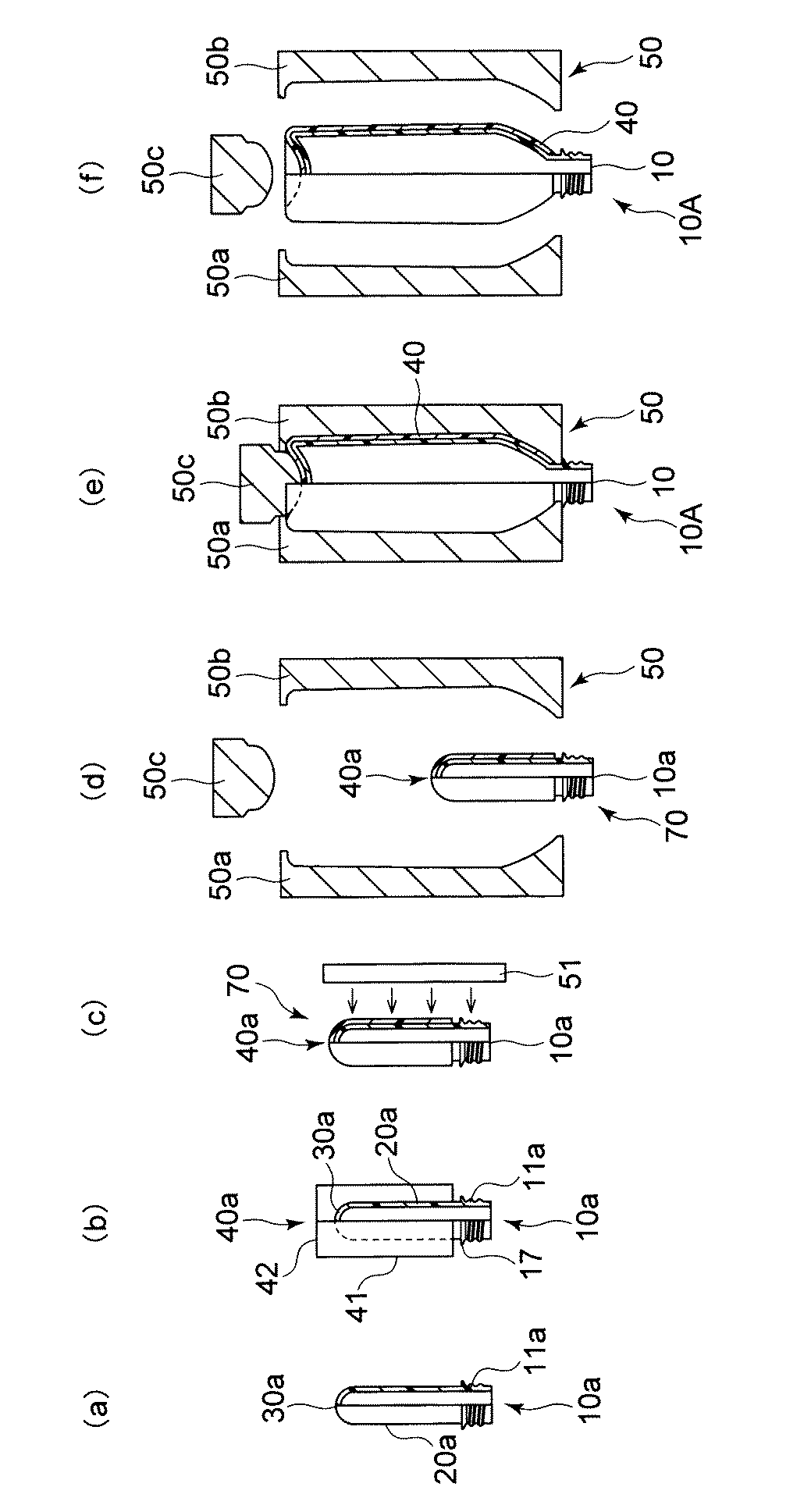
Figure 2017013382
Figure 2017013382

10 容器本体
10A 複合容器
10a プリフォーム
11、11a 口部
12 肩部
13 首部
14 ねじ部
17 フランジ部
20、20a 胴部
30、30a 底部
40、40a プラスチック製部材
41 胴部
42 底部
50 ブロー成形金型
60、60a 内側ラベル部材
61 胴部
62 底部
70 複合プリフォーム
DESCRIPTION OF SYMBOLS 10 Container body 10A Composite container 10a Preform 11, 11a Mouth part 12 Shoulder part 13 Neck part 14 Screw part 17 Flange part 20, 20a Body part 30, 30a Bottom part 40, 40a Plastic member 41 Body part 42 Bottom part 50 Blow molding die 60, 60a Inner label member 61 Body 62 Bottom 70 Composite preform

Claims (7)

複合容器の製造方法において、
口部と、胴部と、底部とを有するとともに、プラスチック材料製のプリフォームを準備する工程と、
前記プリフォームの外側にプラスチック製部材を設ける工程と、
前記プリフォームおよび前記プラスチック製部材に対してブロー成形金型を用いてブロー成形を施すことにより、前記プリフォームおよび前記プラスチック製部材を一体として膨張させ、前記プリフォームに対応する容器本体と、前記容器本体の外側に密着して設けられたプラスチック製部材とを有する複合容器を作製する工程とを備え、
前記複合容器を作製する工程において、前記容器本体に対する前記プリフォームの横方向延伸倍率を3.5倍以下としたことを特徴とする複合容器の製造方法。
In the manufacturing method of the composite container,
A step of preparing a preform made of a plastic material while having a mouth portion, a trunk portion, and a bottom portion;
Providing a plastic member on the outside of the preform;
By subjecting the preform and the plastic member to blow molding using a blow molding die, the preform and the plastic member are expanded as a unit, and a container body corresponding to the preform, A step of producing a composite container having a plastic member provided in close contact with the outside of the container body,
In the step of producing the composite container, a method of manufacturing a composite container, wherein a transverse stretching ratio of the preform with respect to the container body is set to 3.5 times or less.
前記プリフォームの前記胴部の最大厚みは、2mm〜10mmであることを特徴とする請求項1記載の複合容器の製造方法。   The method for manufacturing a composite container according to claim 1, wherein a maximum thickness of the body portion of the preform is 2 mm to 10 mm. ブロー成形前の前記プラスチック製部材の最大厚みは、0.1mm〜2mmであることを特徴とする請求項1又は2記載の複合容器の製造方法。   The method for producing a composite container according to claim 1 or 2, wherein the plastic member before blow molding has a maximum thickness of 0.1 mm to 2 mm. 請求項1記載の複合容器の製造方法に使用されることを特徴とする複合プリフォーム。   A composite preform used in the method for producing a composite container according to claim 1. 前記プリフォームの前記胴部の最大厚みは、2mm〜10mmであることを特徴とする請求項4記載の複合プリフォーム。   The composite preform according to claim 4, wherein a maximum thickness of the body portion of the preform is 2 mm to 10 mm. 前記プラスチック製部材の最大厚みは、0.1mm〜2mmであることを特徴とする請求項4又は5記載の複合プリフォーム。   6. The composite preform according to claim 4, wherein a maximum thickness of the plastic member is 0.1 mm to 2 mm. 複合容器であって、請求項1乃至3のいずれか一項記載の複合容器の製造方法によって作製されたことを特徴とする複合容器。   A composite container produced by the composite container manufacturing method according to any one of claims 1 to 3.
JP2015132977A 2015-07-01 2015-07-01 Manufacturing method of composite container, composite preform and composite container Active JP6776511B2 (en)

Priority Applications (1)

Application Number Priority Date Filing Date Title
JP2015132977A JP6776511B2 (en) 2015-07-01 2015-07-01 Manufacturing method of composite container, composite preform and composite container

Applications Claiming Priority (1)

Application Number Priority Date Filing Date Title
JP2015132977A JP6776511B2 (en) 2015-07-01 2015-07-01 Manufacturing method of composite container, composite preform and composite container

Related Child Applications (1)

Application Number Title Priority Date Filing Date
JP2020169340A Division JP7097007B2 (en) 2020-10-06 2020-10-06 Manufacturing method of composite container, composite preform and composite container

Publications (2)

Publication Number Publication Date
JP2017013382A true JP2017013382A (en) 2017-01-19
JP6776511B2 JP6776511B2 (en) 2020-10-28

Family

ID=57827576

Family Applications (1)

Application Number Title Priority Date Filing Date
JP2015132977A Active JP6776511B2 (en) 2015-07-01 2015-07-01 Manufacturing method of composite container, composite preform and composite container

Country Status (1)

Country Link
JP (1) JP6776511B2 (en)

Cited By (1)

* Cited by examiner, † Cited by third party
Publication number Priority date Publication date Assignee Title
JP2020037414A (en) * 2018-08-31 2020-03-12 大日本印刷株式会社 Composite container

Citations (6)

* Cited by examiner, † Cited by third party
Publication number Priority date Publication date Assignee Title
JP2003136657A (en) * 2001-11-01 2003-05-14 Kureha Chem Ind Co Ltd Multilayer container and method for producing the same
WO2010035654A1 (en) * 2008-09-29 2010-04-01 東洋製罐株式会社 Lightweight multilayered polyester container
JP2010247497A (en) * 2009-04-20 2010-11-04 Kureha Corp Plastic multilayer structure
JP2012076751A (en) * 2010-09-30 2012-04-19 Toyo Seikan Kaisha Ltd Polyester expanded foam container
WO2014208746A1 (en) * 2013-06-28 2014-12-31 大日本印刷株式会社 Blow molding method, composite preform, composite container, inside label member, and plastic-made member
JP2015009487A (en) * 2013-06-28 2015-01-19 大日本印刷株式会社 Blow molding method and composite preform

Patent Citations (6)

* Cited by examiner, † Cited by third party
Publication number Priority date Publication date Assignee Title
JP2003136657A (en) * 2001-11-01 2003-05-14 Kureha Chem Ind Co Ltd Multilayer container and method for producing the same
WO2010035654A1 (en) * 2008-09-29 2010-04-01 東洋製罐株式会社 Lightweight multilayered polyester container
JP2010247497A (en) * 2009-04-20 2010-11-04 Kureha Corp Plastic multilayer structure
JP2012076751A (en) * 2010-09-30 2012-04-19 Toyo Seikan Kaisha Ltd Polyester expanded foam container
WO2014208746A1 (en) * 2013-06-28 2014-12-31 大日本印刷株式会社 Blow molding method, composite preform, composite container, inside label member, and plastic-made member
JP2015009487A (en) * 2013-06-28 2015-01-19 大日本印刷株式会社 Blow molding method and composite preform

Cited By (2)

* Cited by examiner, † Cited by third party
Publication number Priority date Publication date Assignee Title
JP2020037414A (en) * 2018-08-31 2020-03-12 大日本印刷株式会社 Composite container
JP7185840B2 (en) 2018-08-31 2022-12-08 大日本印刷株式会社 Composite container

Also Published As

Publication number Publication date
JP6776511B2 (en) 2020-10-28

Similar Documents

Publication Publication Date Title
JP2016097530A (en) Manufacturing apparatus of composite container, manufacturing method of composite container, composite container and plastic member
JP6738550B2 (en) Composite container, composite preform, method for manufacturing composite container, and plastic member
JP2016120692A (en) Production device of complex preform, complex preform and production method thereof, and composite container and production method thereof
JP2016124136A (en) Composite container and manufacturing method thereof, plastic member, and composite preform
JP6582404B2 (en) Composite container and manufacturing method thereof, composite preform, and plastic member
JP6459325B2 (en) Composite container manufacturing method, composite preform, composite container, and plastic member
JP6663577B2 (en) Composite preform and its manufacturing method, intermediate, and composite container and its manufacturing method
JP6575840B2 (en) Composite container manufacturing method, composite preform, and composite container
JP2016055523A (en) Manufacturing method of composite container for beer, composite preform, composite container for beer, inner label member and plastic member
JP2016120687A (en) Composite container and manufacturing method thereof, plastic member, and composite preform
JP6776511B2 (en) Manufacturing method of composite container, composite preform and composite container
JP2021080027A (en) Composite container, manufacturing method of the same, composite preform, and plastic member
JP7097007B2 (en) Manufacturing method of composite container, composite preform and composite container
JP6868209B2 (en) Composite container with cap and its manufacturing method
JP2016107541A (en) Blow molding method, composite preform, composite container, inner label member and plastic member
JP6489415B2 (en) Manufacturing method of composite container, composite preform, composite container, inner label member, and plastic member
JP6850443B2 (en) Composite containers and their manufacturing methods, composite preforms, and plastic components
JP6853971B2 (en) Composite preforms and their manufacturing methods, intermediates, and composite containers and their manufacturing methods
JP6561458B2 (en) Blow molding method, composite preform, composite container, inner label member and plastic member
JP6668625B2 (en) Method for manufacturing composite container, blow molding die, composite container, composite preform, and plastic member
JP6620966B2 (en) Blow molding method, composite preform, composite container, inner label member and plastic member
JP6458472B2 (en) Blow molding method, composite preform, composite container, inner label member and plastic member
JP2017144584A (en) Composite containers, composite preforms and plastic parts
JP7317463B2 (en) Composite preform and its manufacturing method, and composite container and its manufacturing method
JP2016107540A (en) Blow molding method, composite preform, composite container, inner label member and plastic member

Legal Events

Date Code Title Description
A621 Written request for application examination

Free format text: JAPANESE INTERMEDIATE CODE: A621

Effective date: 20180528

A131 Notification of reasons for refusal

Free format text: JAPANESE INTERMEDIATE CODE: A131

Effective date: 20190723

A521 Request for written amendment filed

Free format text: JAPANESE INTERMEDIATE CODE: A523

Effective date: 20190918

A131 Notification of reasons for refusal

Free format text: JAPANESE INTERMEDIATE CODE: A131

Effective date: 20200228

A521 Request for written amendment filed

Free format text: JAPANESE INTERMEDIATE CODE: A523

Effective date: 20200417

TRDD Decision of grant or rejection written
A01 Written decision to grant a patent or to grant a registration (utility model)

Free format text: JAPANESE INTERMEDIATE CODE: A01

Effective date: 20200908

A61 First payment of annual fees (during grant procedure)

Free format text: JAPANESE INTERMEDIATE CODE: A61

Effective date: 20200921

R150 Certificate of patent or registration of utility model

Ref document number: 6776511

Country of ref document: JP

Free format text: JAPANESE INTERMEDIATE CODE: R150