JP2017014687A - Electric work auxiliary system - Google Patents

Electric work auxiliary system Download PDF

Info

Publication number
JP2017014687A
JP2017014687A JP2015128844A JP2015128844A JP2017014687A JP 2017014687 A JP2017014687 A JP 2017014687A JP 2015128844 A JP2015128844 A JP 2015128844A JP 2015128844 A JP2015128844 A JP 2015128844A JP 2017014687 A JP2017014687 A JP 2017014687A
Authority
JP
Japan
Prior art keywords
cable
distance
construction machine
power supply
controller
Prior art date
Legal status (The legal status is an assumption and is not a legal conclusion. Google has not performed a legal analysis and makes no representation as to the accuracy of the status listed.)
Pending
Application number
JP2015128844A
Other languages
Japanese (ja)
Inventor
小平 龍
Shohei Ryu
小平 龍
釣賀 靖貴
Yasutaka Tsuriga
靖貴 釣賀
伊君 高志
Takashi Ikimi
高志 伊君
豊 渡邊
Yutaka Watanabe
豊 渡邊
晃司 塩飽
Koji Shiwaku
晃司 塩飽
好 中山
Yoshi Nakayama
好 中山
Current Assignee (The listed assignees may be inaccurate. Google has not performed a legal analysis and makes no representation or warranty as to the accuracy of the list.)
Hitachi Construction Machinery Co Ltd
Original Assignee
Hitachi Construction Machinery Co Ltd
Priority date (The priority date is an assumption and is not a legal conclusion. Google has not performed a legal analysis and makes no representation as to the accuracy of the date listed.)
Filing date
Publication date
Application filed by Hitachi Construction Machinery Co Ltd filed Critical Hitachi Construction Machinery Co Ltd
Priority to JP2015128844A priority Critical patent/JP2017014687A/en
Publication of JP2017014687A publication Critical patent/JP2017014687A/en
Pending legal-status Critical Current

Links

Images

Landscapes

  • Operation Control Of Excavators (AREA)
  • Component Parts Of Construction Machinery (AREA)

Abstract

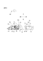
PROBLEM TO BE SOLVED: To mitigate a load on an operator.SOLUTION: An electric work auxiliary system comprises: a construction machine comprising a traveling body, a revolving superstructure provided on the traveling body, a work device provided on the revolving superstructure, a hydraulic pump for supplying pressure oil for driving each of the traveling body, the revolving superstructure, and the work device, and an electric motor for driving the hydraulic pump; a power supply vehicle comprising a power supply device for supplying power, through a cable, to the electric motor mounted on the construction machine; an imaging device provided in at least either of the construction machine and the power supply vehicle; and a control device for determining whether or not a distance between the construction machine and the cable is shorter than a predetermined distance, on the basis of a picture imaged by the imaging device. The control device, when it has been determined that distance between the construction machine and the cable is shorter than the predetermined distance, transmits predetermined information to an information terminal.SELECTED DRAWING: Figure 4

Description

本発明は、電動作業補助システムに関する。   The present invention relates to an electric work assistance system.

近年、建設機械の作業現場において、省エネルギー化や耐環境性向上の要求が高まりつつある。それに呼応するため、建機メーカではエンジンの代わりに電動モータを搭載し、油圧システムを駆動する電動式建設機械を提供している。特許文献1には、バッテリと、バッテリに接続されるインバータとを備えた電源車にケーブルを介して接続可能な電動式建設機械が記載されている。   In recent years, there has been a growing demand for energy saving and environmental resistance improvement at the construction machine work site. In response, construction equipment manufacturers are providing electric construction machines that are equipped with electric motors instead of engines and drive hydraulic systems. Patent Document 1 describes an electric construction machine that can be connected via a cable to a power supply vehicle that includes a battery and an inverter connected to the battery.

特開2014−118773号公報JP 2014-118773 A

特許文献1に記載の電動式建設機械は、電源車にケーブルを介して接続されているので、運転者は、ケーブルがクローラに踏まれてしまうことがないように、注意を払いながら作業を行う必要があり、運転者の負担が大きいという課題があった。   Since the electric construction machine described in Patent Document 1 is connected to the power supply vehicle via a cable, the driver works with care so that the cable is not stepped on by the crawler. There was a problem that it was necessary and the burden on the driver was large.

請求項1に記載の電動作業補助システムは、走行体、走行体上に設けられた旋回体、旋回体に設けられた作業装置、ならびに、走行体、旋回体、および作業装置のそれぞれを駆動するための圧油を供給する油圧ポンプ、ならびに、油圧ポンプを駆動する電動モータを備えた建設機械と、建設機械に搭載された電動モータにケーブルを介して電力を供給する電源装置を備えた電源車と、建設機械および電源車の少なくとも一方に設けられた撮影装置と、撮影装置により撮影された画像に基づいて、建設機械とケーブルとの距離が所定距離よりも小さいか否かを判定する制御装置とを備え、制御装置は、建設機械とケーブルとの距離が所定距離よりも小さいと判定された場合に、所定情報を情報端末に送信する。   The electric work assist system according to claim 1 drives each of the traveling body, the swing body provided on the travel body, the work device provided on the swing body, and the travel body, the swing body, and the work device. Power supply vehicle including a hydraulic pump that supplies pressure oil for use, a construction machine having an electric motor that drives the hydraulic pump, and a power supply device that supplies power to the electric motor mounted on the construction machine via a cable And a control device for determining whether or not the distance between the construction machine and the cable is smaller than a predetermined distance based on an imaging device provided in at least one of the construction machine and the power supply vehicle and an image captured by the imaging device The control device transmits predetermined information to the information terminal when it is determined that the distance between the construction machine and the cable is smaller than the predetermined distance.

本発明によれば、ケーブルが建設機械に接近した場合に、情報端末を介して運転者や現場作業員、現場監督者等に知らせることができるので、運転者の負担を軽減することができる。   According to the present invention, when the cable approaches the construction machine, it is possible to notify the driver, the field worker, the site supervisor, etc. via the information terminal, so that the burden on the driver can be reduced.

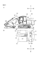
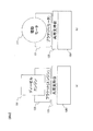
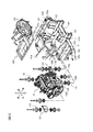
建設機械の一例である油圧ショベルの側面図および平面図。A side view and a top view of a hydraulic excavator which is an example of a construction machine. エンジンまたは電動モータを支持する共用支持台について説明する模式図。The schematic diagram explaining the common support stand which supports an engine or an electric motor. エンジン用ブラケットおよび共用支持台を示す斜視図。The perspective view which shows the bracket for engines and a common support stand. 第1の実施の形態に係る電動作業補助システムの構成を示す側面模式図。The side surface schematic diagram which shows the structure of the electric work assistance system which concerns on 1st Embodiment. 電動作業補助システムの構成を示すブロック図。The block diagram which shows the structure of an electrically-driven work assistance system. (a)は油圧ショベルと電源車との位置関係を示す平面模式図、(b)は油圧ショベルのカウンタウエイトの後面に塗装されたシンボルマークを示す模式図、(c)は、カメラで撮影された画像を示す模式図、(d)は1画素あたりの長さの求め方について説明する図であり、(e)はクローラとケーブルとの最短距離の求め方について説明する図。(A) is a schematic plan view showing the positional relationship between the hydraulic excavator and the power supply vehicle, (b) is a schematic diagram showing a symbol mark painted on the rear surface of the counterweight of the hydraulic excavator, and (c) is taken by a camera. FIG. 4D is a diagram for explaining how to obtain the length per pixel, and FIG. 4E is a diagram for explaining how to obtain the shortest distance between the crawler and the cable. コントローラによるケーブル巻取駆動処理および過荷重警報送信処理の内容を示すフローチャート。The flowchart which shows the content of the cable winding drive process and overload warning transmission process by a controller. 油圧ショベルと電源車との相対位置の変化の一例を示す平面模式図。The plane schematic diagram which shows an example of the change of the relative position of a hydraulic excavator and a power supply vehicle. 第2の実施の形態に係る電動作業補助システムを構成する油圧ショベル、電源車およびケーブルを示す平面模式図。The plane schematic diagram which shows the hydraulic excavator, power supply vehicle, and cable which comprise the electric work assistance system which concerns on 2nd Embodiment. (a)は第3の実施の形態に係るコントローラにおける警報送信処理の一例を示すフローチャート。(b)は第4の実施の形態に係るコントローラにおける警報送信処理の一例を示すフローチャート。(A) is a flowchart which shows an example of the alarm transmission process in the controller which concerns on 3rd Embodiment. (B) is a flowchart which shows an example of the alarm transmission process in the controller which concerns on 4th Embodiment. 第5の実施の形態に係るコントローラにおけるケーブル巻取駆動処理の一例を示すフローチャート。The flowchart which shows an example of the cable winding drive process in the controller which concerns on 5th Embodiment. ケーブルの配置状態の一例を示す模式図。The schematic diagram which shows an example of the arrangement | positioning state of a cable. 変形例2に係る電動作業補助システムの構成を示す側面模式図。The side surface schematic diagram which shows the structure of the electric work assistance system which concerns on the modification 2. As shown in FIG. コントローラにおける接近警報送信処理の一例を示すフローチャート。The flowchart which shows an example of the approach warning transmission process in a controller. 変形例5に係る電動作業補助システムの構成を示す模式図。The schematic diagram which shows the structure of the electrically-driven work assistance system which concerns on the modification 5. FIG.

−第1の実施の形態−
図1(a)および図1(b)は、建設機械の一例である油圧ショベル100の側面図および平面図である。なお、説明の便宜上、図1の姿勢を基準に油圧ショベル100の前後、上下および左右方向を規定する。図1に示す油圧ショベル100は、走行体102と、走行体102上に設けられた旋回体105とを備えている。旋回体105は、旋回機構により走行体102に対して旋回可能に設けられている。旋回機構には、旋回体105を旋回させる油圧モータ(以下、旋回モータと記す)が設けられている。
-First embodiment-
Fig.1 (a) and FIG.1 (b) are the side views and top views of the hydraulic excavator 100 which are examples of a construction machine. For convenience of explanation, the front and rear, the top and bottom, and the left and right directions of the excavator 100 are defined based on the posture of FIG. A hydraulic excavator 100 illustrated in FIG. 1 includes a traveling body 102 and a revolving body 105 provided on the traveling body 102. The turning body 105 is provided so as to be turnable with respect to the traveling body 102 by a turning mechanism. The turning mechanism is provided with a hydraulic motor (hereinafter referred to as a turning motor) for turning the turning body 105.

走行体102には、走行用の油圧モータ(以下、走行モータ106と記す)が搭載されている。走行体102は、左右の走行モータ106により左右のクローラ103を駆動することで走行する。   The traveling body 102 is mounted with a traveling hydraulic motor (hereinafter referred to as a traveling motor 106). The traveling body 102 travels by driving the left and right crawlers 103 by the left and right traveling motors 106.

旋回体105の前部には、掘削作業を行うフロント作業装置110が設けられている。フロント作業装置110は、ブーム107、アーム108、および、バケット109を含む。ブーム107は、旋回体105を構成するフレーム(以下、旋回フレーム105fと記す)において、旋回体105に対して上下方向に回動可能に取り付けられている。ブーム107は、ブーム起伏用の油圧シリンダ(以下、ブームシリンダ107aと記す)によって駆動されて起伏する。   A front working device 110 that performs excavation work is provided at the front of the revolving structure 105. The front work device 110 includes a boom 107, an arm 108, and a bucket 109. The boom 107 is attached so as to be rotatable in the vertical direction with respect to the swing body 105 in a frame constituting the swing body 105 (hereinafter referred to as a swing frame 105f). The boom 107 is driven by a boom raising / lowering hydraulic cylinder (hereinafter referred to as a boom cylinder 107a) to rise and fall.

アーム108は、ブーム107の先端において、ブーム107に対して上下方向に回動可能に取り付けられている。アーム108は、アーム起伏用の油圧シリンダ(以下、アームシリンダ108aと記す)によって駆動されて起伏する。バケット109は、アーム108の先端において、アーム108に対して上下方向に回動可能に取り付けられ、バケット起伏用の油圧シリンダ(以下、バケットシリンダ109aと記す)によって駆動される。   The arm 108 is attached to the boom 107 so as to be rotatable in the vertical direction with respect to the boom 107. The arm 108 is driven to rise and fall by a hydraulic cylinder for raising and lowering the arm (hereinafter referred to as an arm cylinder 108a). The bucket 109 is attached at the tip of the arm 108 so as to be pivotable in the vertical direction with respect to the arm 108, and is driven by a hydraulic cylinder for raising and lowering the bucket (hereinafter referred to as a bucket cylinder 109a).

旋回体105には、油圧ショベル100を操縦する運転者が搭乗する運転室(キャブ)104が設けられている。運転室104内には各種操作部材が配設されている。旋回体105の後部には、フロント作業装置110とのバランスをとるために、カウンタウエイト101が配設されている。図1(b)に示すように、旋回体105におけるカウンタウエイト101の前方には、電動モータ111および油圧ポンプ112、小型発電機113、および補機用バッテリ114が配設されている。電動モータ111および油圧ポンプ112の上面側および側面側は、建屋カバー119(図1(a)参照、図1(b)において不図示)によって覆われている。   The swivel body 105 is provided with a cab 104 where a driver operating the excavator 100 rides. Various operation members are disposed in the cab 104. A counterweight 101 is disposed at the rear part of the revolving unit 105 in order to balance the front working device 110. As shown in FIG. 1B, an electric motor 111 and a hydraulic pump 112, a small generator 113, and an auxiliary battery 114 are disposed in front of the counterweight 101 in the swing body 105. The upper surface side and the side surface side of the electric motor 111 and the hydraulic pump 112 are covered with a building cover 119 (see FIG. 1A, not shown in FIG. 1B).

電動モータ111、油圧ポンプ112、および小型発電機113の回動軸は、それぞれ油圧ショベル100の左右方向に延在している。電動モータ111は、後述する電源車130(図4参照)から供給される電力によって回転駆動する。   The rotation shafts of the electric motor 111, the hydraulic pump 112, and the small generator 113 extend in the left-right direction of the hydraulic excavator 100, respectively. The electric motor 111 is rotationally driven by electric power supplied from a power supply car 130 (see FIG. 4) described later.

油圧ポンプ112は、電動モータ111によって駆動されて作動油を吐出する。油圧ポンプ112から吐出された作動油は、図示しないコントロールバルブを介して、フロント作業装置110を駆動する各アクチュエータ(ブームシリンダ107a、アームシリンダ108a、およびバケットシリンダ109a)や、旋回機構を駆動する旋回モータ(不図示)、走行体102を駆動する走行モータ106に供給される。つまり、駆動源である電動モータ111によって、油圧ポンプ112が駆動され、油圧ポンプ112から各アクチュエータに圧油を供給することで、走行体102、旋回体105およびフロント作業装置110のそれぞれが駆動される。   The hydraulic pump 112 is driven by the electric motor 111 to discharge hydraulic oil. The hydraulic oil discharged from the hydraulic pump 112 is turned to drive each of the actuators (the boom cylinder 107a, the arm cylinder 108a, and the bucket cylinder 109a) that drives the front work device 110 and the turning mechanism via a control valve (not shown). A motor (not shown) is supplied to a traveling motor 106 that drives the traveling body 102. That is, the hydraulic pump 112 is driven by the electric motor 111 that is a driving source, and the hydraulic oil is supplied from the hydraulic pump 112 to each actuator, whereby each of the traveling body 102, the swinging body 105, and the front work device 110 is driven. The

小型発電機113は、電動モータ111が回転することにより発電する。小型発電機113で発生した電力は、補機用バッテリ114に供給され、補機用バッテリ114が充電される。補機用バッテリ114は、運転室104に配設される各種補機やコントローラへ電力を供給する電源装置である。   The small generator 113 generates electricity when the electric motor 111 rotates. The electric power generated by the small generator 113 is supplied to the auxiliary battery 114, and the auxiliary battery 114 is charged. The auxiliary battery 114 is a power supply device that supplies electric power to various auxiliary machines and controllers arranged in the cab 104.

図2は、エンジン191または電動モータ111を支持する共用支持台125について説明する模式図である。本実施の形態では、電動モータ111に代えて、エンジン191を支持可能な強度、形状とされた共用支持台125を備えている。図2(a)は、エンジン191をエンジン用ブラケット129を介して、共用支持台125に接続し、エンジン191を共用支持台125により支持させた状態を示している。図2(b)は、電動モータ111をモータ用ブラケット121を介して、共用支持台125に接続し、電動モータ111を共用支持台125に支持させた状態を示している。   FIG. 2 is a schematic diagram for explaining the common support stand 125 that supports the engine 191 or the electric motor 111. In the present embodiment, instead of the electric motor 111, a shared support base 125 having a strength and shape capable of supporting the engine 191 is provided. FIG. 2A shows a state where the engine 191 is connected to the common support base 125 via the engine bracket 129 and the engine 191 is supported by the common support base 125. FIG. 2B shows a state in which the electric motor 111 is connected to the common support base 125 via the motor bracket 121, and the electric motor 111 is supported by the common support base 125.

図3は、エンジン用ブラケット129および共用支持台125を示す斜視図である。図3では、旋回フレーム105fの全体斜視図(右上図)、旋回フレーム105fの一部(右上図のA部)を拡大した斜視図(右下図)、およびエンジン191の斜視図(左図)を図示している。図3を参照して、エンジン191と共用支持台125との接続構造について説明する。なお、電動モータ111と共用支持台125との接続構造は、エンジン191と共用支持台125との接続構造と同様となるので、説明を省略する。   FIG. 3 is a perspective view showing the engine bracket 129 and the shared support base 125. FIG. 3 is an overall perspective view (upper right view) of the turning frame 105f, an enlarged perspective view (lower right view) of a part of the turning frame 105f (A portion in the upper right view), and a perspective view (left view) of the engine 191. It is shown. A connection structure between the engine 191 and the shared support stand 125 will be described with reference to FIG. Note that the connection structure between the electric motor 111 and the common support base 125 is the same as the connection structure between the engine 191 and the common support base 125, and thus the description thereof is omitted.

図3に示すように、旋回フレーム105fの後部には、エンジン191(または電動モータ111)を支持する共用支持台125が設けられている。共用支持台125は、平面視でコ字状の保持フレーム151と、保持フレーム151に固着される4つの支持脚152とを備えている。保持フレーム151は、前後方向に延びる一対の縦板151aと、一対の縦板151aの前端で、一対の縦板151a同士を連結する連結板151bとを備えている。   As shown in FIG. 3, a common support base 125 that supports the engine 191 (or the electric motor 111) is provided at the rear portion of the turning frame 105 f. The common support stand 125 includes a U-shaped holding frame 151 in plan view and four support legs 152 fixed to the holding frame 151. The holding frame 151 includes a pair of vertical plates 151a extending in the front-rear direction and a connecting plate 151b that connects the pair of vertical plates 151a at the front ends of the pair of vertical plates 151a.

4つの支持脚152は、互いに略同一平面上に位置する載置面を有する載置板152aを備えている。4つの支持脚152は、それぞれ載置板152aと保持フレーム151とを連結する連結部を備えている。   The four support legs 152 are provided with mounting plates 152a having mounting surfaces that are located on substantially the same plane. Each of the four support legs 152 includes a connecting portion that connects the mounting plate 152 a and the holding frame 151.

エンジン191には、4つのエンジン用ブラケット129が着脱自在に取り付けられる。載置板152aには、ラバーマウント128の構成部品であるボルトが挿通される貫通孔152hが形成されている。各エンジン用ブラケット129は、各支持脚152の載置板152a上に載置される。各エンジン用ブラケット129は、ラバーマウント128を介して支持脚152の載置板152aに取り付けられる。   Four engine brackets 129 are detachably attached to the engine 191. The mounting plate 152a is formed with a through hole 152h through which a bolt that is a component of the rubber mount 128 is inserted. Each engine bracket 129 is placed on a placement plate 152 a of each support leg 152. Each engine bracket 129 is attached to the mounting plate 152 a of the support leg 152 via the rubber mount 128.

エンジン用ブラケット129は、エンジン191の側部に接続される接続板129aと、接続板129aの下端から側方に延びる取付板129bと、取付板129bおよび接続板129aのそれぞれに接続されてエンジン用ブラケット129の剛性を高める補強リブ129cとを備えている。なお、取付板129bおよび接続板129aにより、エンジン用ブラケット129の十分な剛性が確保できる場合には、補強リブ129cを省略することもできる。つまり、エンジン191を共用支持台125によって支持させる場合、エンジン191は、4つのエンジン用ブラケット129を介して、共用支持台125によって支持される。   The engine bracket 129 is connected to each of the connection plate 129a connected to the side portion of the engine 191, the attachment plate 129b extending from the lower end of the connection plate 129a, the attachment plate 129b, and the connection plate 129a. Reinforcing ribs 129c that increase the rigidity of the bracket 129 are provided. When the mounting plate 129b and the connection plate 129a can secure sufficient rigidity of the engine bracket 129, the reinforcing rib 129c can be omitted. That is, when the engine 191 is supported by the common support base 125, the engine 191 is supported by the common support base 125 via the four engine brackets 129.

図示しないが、電動モータ111を共用支持台125に取り付ける場合、電動モータ111に4つのモータ用ブラケット121(図2(b)参照)を取り付け、モータ用ブラケット121をラバーマウント128を介して支持脚152の載置板152aに取り付ければよい。電動モータ111を取り付ける場合であっても、上述した貫通孔152hにラバーマウント128を構成するボルトを挿通し、ナットをボルトの先端部に螺合することで、モータ用ブラケット121を共用支持台125に締結固定することができる。つまり、電動モータ111を共用支持台125によって支持させる場合、電動モータ111は、4つのモータ用ブラケット121を介して、共用支持台125によって支持される。このように、本実施の形態では、エンジン用ブラケット129と、モータ用ブラケット121の構造がそれぞれ、共用支持台125に取り付け可能な構成とされている。   Although not shown, when the electric motor 111 is attached to the common support base 125, four motor brackets 121 (see FIG. 2B) are attached to the electric motor 111, and the motor bracket 121 is attached to the support legs via the rubber mount 128. What is necessary is just to attach to the mounting board 152a of 152. Even when the electric motor 111 is attached, the bolt 121 constituting the rubber mount 128 is inserted into the through-hole 152h described above, and the nut is screwed to the tip of the bolt, so that the motor bracket 121 can be attached to the common support base 125. Can be fastened and fixed. That is, when the electric motor 111 is supported by the common support base 125, the electric motor 111 is supported by the common support base 125 via the four motor brackets 121. As described above, in the present embodiment, the structures of the engine bracket 129 and the motor bracket 121 are each configured to be attachable to the common support base 125.

図4は、第1の実施の形態に係る電動作業補助システムの構成を示す側面模式図である。電動作業補助システムは、油圧ショベル100と、電源車130と、油圧ショベル100と電源車130とを接続するケーブル140とを含んで構成される。図4に示すように、油圧ショベル100の後方に電源車130が位置している。電源車130は、バッテリ131と、インバータ132とを有する電源装置を備えている。バッテリ131は、リチウムイオン二次電池を複数備える蓄電装置であり、電源車130から容易に着脱できる構成とされている。バッテリ131とインバータ132との間は、着脱自在のケーブル141で接続されており、ケーブル141を通してバッテリ131の直流電力をインバータ132に供給する。インバータ132は、内部に備えられたトランジスタで構成されたスイッチング回路(不図示)を用いて、バッテリ131の直流電力を三相交流電力に変換し、電動モータ111へ電力を供給している。   FIG. 4 is a schematic side view illustrating the configuration of the electric work assistance system according to the first embodiment. The electric work assistance system includes a hydraulic excavator 100, a power supply vehicle 130, and a cable 140 that connects the hydraulic excavator 100 and the power supply vehicle 130. As shown in FIG. 4, the power supply wheel 130 is located behind the excavator 100. The power supply vehicle 130 includes a power supply device having a battery 131 and an inverter 132. The battery 131 is a power storage device including a plurality of lithium ion secondary batteries, and is configured to be easily detached from the power supply vehicle 130. The battery 131 and the inverter 132 are connected by a detachable cable 141, and the DC power of the battery 131 is supplied to the inverter 132 through the cable 141. The inverter 132 converts the DC power of the battery 131 into three-phase AC power using a switching circuit (not shown) configured by a transistor provided therein, and supplies the electric motor 111 with power.

インバータ132から供給された電力はケーブル140を介して、油圧ショベル100に供給される。ケーブル140は油圧ショベル100の旋回体105上にあるケーブルスタンド142にガイドされ、ケーブルスタンド142のコネクタ143に接続される。ケーブルスタンド142は、旋回体105に対して回動可能な回動軸142aと、回動軸142aの上端部から水平方向に延在するガイド部材142bとを備えている。回動軸142aは、ベアリング142cを介して旋回体105に保持されている。ベアリング142cは、内周側が回動軸142aに固定され、外周側が旋回体105に固定される。   The electric power supplied from the inverter 132 is supplied to the excavator 100 via the cable 140. The cable 140 is guided by a cable stand 142 on the swing body 105 of the excavator 100 and connected to a connector 143 of the cable stand 142. The cable stand 142 includes a rotating shaft 142a that can rotate with respect to the revolving body 105, and a guide member 142b that extends in the horizontal direction from the upper end of the rotating shaft 142a. The rotation shaft 142a is held by the revolving body 105 via a bearing 142c. The bearing 142 c has an inner peripheral side fixed to the rotating shaft 142 a and an outer peripheral side fixed to the swing body 105.

ガイド部材142bはケーブル140の一端部を保持しており、ガイド部材142bの先端からはケーブル140が地面に向かって垂れ下がっている。旋回体105が一方に回動すると、ケーブル140の重力の作用で、ケーブルスタンド142が回動軸142aを回転中心として旋回方向とは逆の方向に回動する。このため、ケーブルスタンド142が無い場合に比べて、ケーブル140の移動量を低減することができる。   The guide member 142b holds one end of the cable 140, and the cable 140 hangs from the tip of the guide member 142b toward the ground. When the turning body 105 rotates to one side, the cable stand 142 rotates about the rotation shaft 142a in the direction opposite to the turning direction by the action of the gravity of the cable 140. For this reason, compared with the case where there is no cable stand 142, the movement amount of the cable 140 can be reduced.

ケーブル140は三相交流電力を供給できるように、ケーブル140内に1本の配線からなる単線を複数包含した構成となっている。なお、本実施形態にかかる油圧ショベル100は、商用電源(不図示)と電源車130とを選択的に接続できる構成となっている。   The cable 140 has a configuration in which a plurality of single wires made of one wiring are included in the cable 140 so that three-phase AC power can be supplied. The hydraulic excavator 100 according to the present embodiment is configured to selectively connect a commercial power source (not shown) and the power supply vehicle 130.

図5は、電動作業補助システムの構成を示すブロック図である。図5(a)に示すように、電源車130は、コントローラ160と、撮影装置であるカメラ170と、ケーブル巻取装置180と、ケーブル140の張力を検出する張力検出装置190とを備えている。   FIG. 5 is a block diagram showing a configuration of the electric work assistance system. As illustrated in FIG. 5A, the power supply vehicle 130 includes a controller 160, a camera 170 that is a photographing device, a cable winding device 180, and a tension detection device 190 that detects the tension of the cable 140. .

コントローラ160は、CPUや記憶装置であるROMおよびRAM、その他の周辺回路などを有する演算処理装置を含んで構成されている。コントローラ160には、カメラ170からの撮像信号や、張力検出装置190からの張力信号が入力される。コントローラ160は、後述するように、撮像信号や張力信号に基づいて、ケーブル巻取装置180を制御したり、油圧ショベル100の運転室104内に配設される情報端末200や現場作業員および/または現場監督者が利用する情報端末300に警報等の情報を送信したりする。   The controller 160 is configured to include an arithmetic processing unit having a CPU and a storage device such as ROM and RAM, and other peripheral circuits. An imaging signal from the camera 170 and a tension signal from the tension detector 190 are input to the controller 160. As will be described later, the controller 160 controls the cable winding device 180 on the basis of the imaging signal and the tension signal, and the information terminal 200 and the field worker and / or the operator who is disposed in the cab 104 of the excavator 100. Alternatively, information such as an alarm is transmitted to the information terminal 300 used by the site supervisor.

カメラ170は、撮像光学系や、撮像素子等を備えている。撮像素子は、たとえばCMOSやCCD等であり、撮像光学系により結像された被写体像を撮像して撮像信号をコントローラ160に送信する。カメラ170は、ケーブル140と油圧ショベル100を常時、撮影できるような位置に配置される。   The camera 170 includes an imaging optical system, an imaging element, and the like. The imaging element is, for example, a CMOS or CCD, and captures a subject image formed by the imaging optical system and transmits an imaging signal to the controller 160. The camera 170 is disposed at a position where the cable 140 and the excavator 100 can be always photographed.

ケーブル巻取装置180は、ケーブル140が巻回されるドラム(不図示)と、ドラムを駆動するモータ(不図示)とを備えている。ケーブル140にある程度の張力が作用すると、ドラムからケーブル140が繰り出される。ケーブル巻取装置180は、モータ(不図示)によりドラム(不図示)を回転駆動することで、ドラムによってケーブル140を巻き取ることができる。ケーブル巻取装置180は、コントローラ160から出力された駆動信号(巻き取り信号)が入力されることで、モータ(不図示)が回転駆動する。ケーブル巻取装置180は、コントローラ160から出力された停止信号が入力されることで、モータ(不図示)が停止する。コントローラ160は、後述する第1巻き取り条件および第2巻き取り条件の双方が成立した場合に、ケーブル巻取装置180の駆動信号(巻き取り信号)を出力し、後述する第1巻き取り停止条件または第2巻き取り停止条件が成立した場合に、ケーブル巻取装置180の停止信号を出力する。   The cable winding device 180 includes a drum (not shown) around which the cable 140 is wound, and a motor (not shown) that drives the drum. When a certain amount of tension acts on the cable 140, the cable 140 is unwound from the drum. The cable winding device 180 can wind the cable 140 with the drum by rotating the drum (not shown) with a motor (not shown). In the cable winding device 180, when a drive signal (winding signal) output from the controller 160 is input, a motor (not shown) is rotationally driven. In the cable winding device 180, the motor (not shown) stops when the stop signal output from the controller 160 is input. The controller 160 outputs a drive signal (winding signal) for the cable winding device 180 when both a first winding condition and a second winding condition described later are satisfied, and a first winding stop condition described later. Alternatively, when the second winding stop condition is satisfied, a stop signal of the cable winding device 180 is output.

コントローラ160は、条件判定部161と、距離演算部165と、距離閾値設定部166と、警報送信部167とを機能的に備える。距離演算部165は、ケーブル140と油圧ショベル100の走行体102との最短距離Xを演算する。距離演算部165による最短距離Xの演算方法については後述する。   The controller 160 functionally includes a condition determination unit 161, a distance calculation unit 165, a distance threshold setting unit 166, and an alarm transmission unit 167. The distance calculation unit 165 calculates the shortest distance X between the cable 140 and the traveling body 102 of the excavator 100. A method of calculating the shortest distance X by the distance calculation unit 165 will be described later.

条件判定部161は、張力検出装置190で検出された張力F1が、第1閾値Fa未満であるか否かを判定する。条件判定部161は、張力F1が第1閾値Fa以上である場合、第1巻き取り条件が非成立であると判定する。条件判定部161は、張力F1が第1閾値Fa未満である場合、第1巻き取り条件が成立していると判定する。第1閾値Faは、油圧ショベル100と電源車130との距離が離れるように、油圧ショベル100および/または電源車130が移動したこと、あるいは油圧ショベル100が旋回動作したことに起因して、ケーブル140がケーブル巻取装置180から繰り出されたことを判定する閾値である。本実施の形態では、ケーブル140に作用する張力F1が第1閾値Fa以上の場合に、ケーブル140がドラムから繰り出される。第1閾値Faは、予めコントローラ160の記憶装置に記憶されている。   The condition determination unit 161 determines whether the tension F1 detected by the tension detector 190 is less than the first threshold value Fa. The condition determination unit 161 determines that the first winding condition is not satisfied when the tension F1 is equal to or greater than the first threshold value Fa. The condition determination unit 161 determines that the first winding condition is satisfied when the tension F1 is less than the first threshold value Fa. The first threshold value Fa is determined by the movement of the excavator 100 and / or the power supply vehicle 130 so that the distance between the excavator 100 and the power supply vehicle 130 is increased, or the rotation of the excavator 100. 140 is a threshold value for determining that the cable winding device 180 has been fed out. In the present embodiment, when the tension F1 acting on the cable 140 is equal to or greater than the first threshold value Fa, the cable 140 is unwound from the drum. The first threshold value Fa is stored in advance in the storage device of the controller 160.

条件判定部161は、張力F1が警報用張力閾値Fmax未満であるか否かを判定する。条件判定部161は、張力F1が警報用張力閾値Fmax未満である場合、張力警報条件が非成立であると判定し、張力F1が警報用張力閾値Fmax以上の場合、張力警報条件が成立していると判定する。警報用張力閾値Fmaxは、予めコントローラ160の記憶装置に記憶されている。警報用張力閾値Fmaxは、ケーブル140が損傷することを防止するために設定される閾値であり、ケーブル140の許容張力以下の値に設定される。   The condition determination unit 161 determines whether or not the tension F1 is less than the alarm tension threshold Fmax. The condition determination unit 161 determines that the tension alarm condition is not satisfied when the tension F1 is less than the alarm tension threshold Fmax, and the tension alarm condition is satisfied when the tension F1 is equal to or greater than the alarm tension threshold Fmax. It is determined that The alarm tension threshold value Fmax is stored in the storage device of the controller 160 in advance. The alarm tension threshold value Fmax is a threshold value set to prevent the cable 140 from being damaged, and is set to a value equal to or lower than the allowable tension of the cable 140.

第1巻き取り条件が成立すると、条件判定部161は、距離演算部165で演算された最短距離Xが距離閾値La未満であるか否かを判定する。条件判定部161は、最短距離Xが距離閾値La以上である場合、第2巻き取り条件が非成立であると判定し、最短距離Xが距離閾値La未満である場合、第2巻き取り条件が成立していると判定する。距離閾値Laは、油圧ショベル100とケーブル140との距離が近づいたことを判定し、ケーブル巻取装置180によるケーブル140の巻き取り動作を実行させるための閾値であり、予めコントローラ160の記憶装置に記憶されている。   When the first winding condition is satisfied, the condition determination unit 161 determines whether or not the shortest distance X calculated by the distance calculation unit 165 is less than the distance threshold La. The condition determination unit 161 determines that the second winding condition is not satisfied when the shortest distance X is equal to or greater than the distance threshold La, and the second winding condition is determined when the shortest distance X is less than the distance threshold La. It is determined that it has been established. The distance threshold value La is a threshold value for determining that the distance between the excavator 100 and the cable 140 is near and causing the cable winding device 180 to perform the winding operation of the cable 140. The distance threshold value La is stored in the storage device of the controller 160 in advance. It is remembered.

距離閾値設定部166は、第2巻き取り条件が成立した場合に、最短距離Xを距離閾値Xcとして設定する。距離閾値Xcは、第2巻き取り条件成立後に最短距離Xが増加したか否かを判定するための閾値として設定され、コントローラ160の記憶装置に記憶される。距離閾値Xcは、所定制御周期ごとに設定される。すなわち、最短距離Xが増加すると、距離閾値Xcも増加する。   The distance threshold setting unit 166 sets the shortest distance X as the distance threshold Xc when the second winding condition is satisfied. The distance threshold value Xc is set as a threshold value for determining whether or not the shortest distance X has increased after the second winding condition is satisfied, and is stored in the storage device of the controller 160. The distance threshold value Xc is set for each predetermined control period. That is, when the shortest distance X increases, the distance threshold value Xc also increases.

条件判定部161は、距離演算部165で演算された最短距離Xが距離閾値Xc未満であるか否かを判定する。条件判定部161は、最短距離Xが距離閾値Xc未満である場合、すなわち最短距離Xが減少していることが判定された場合、巻き返しにより、クローラ103がケーブル140を踏むリスクが増加したものとして、第1巻き取り停止条件が成立していると判定する。条件判定部161は、最短距離Xが距離閾値Xc以上である場合、巻き返しにより、クローラ103がケーブル140を踏むリスクが低下したものとして、第1巻き取り停止条件が非成立であると判定する。   The condition determination unit 161 determines whether or not the shortest distance X calculated by the distance calculation unit 165 is less than the distance threshold value Xc. When the shortest distance X is less than the distance threshold Xc, that is, when it is determined that the shortest distance X is decreasing, the condition determination unit 161 assumes that the risk that the crawler 103 steps on the cable 140 increases due to rewinding. Then, it is determined that the first winding stop condition is satisfied. When the shortest distance X is equal to or greater than the distance threshold value Xc, the condition determination unit 161 determines that the first winding stop condition is not satisfied, assuming that the risk of the crawler 103 stepping on the cable 140 has decreased due to rewinding.

第1巻き取り停止条件が非成立である場合、条件判定部161は、張力検出装置190で検出された張力F1が、第2閾値Fb以上であるか否かを判定する。条件判定部161は、張力F1が第2閾値Fb未満である場合、第2巻き取り停止条件が非成立であると判定し、張力F1が第2閾値Fb以上である場合、第2巻き取り停止条件が成立していると判定する。第2閾値Fbは、第1閾値Fa未満であって、撓んだケーブル140が直線状に配置されたことを判定するための閾値であり、予めコントローラ160の記憶装置に記憶されている。   When the first winding stop condition is not satisfied, the condition determination unit 161 determines whether the tension F1 detected by the tension detector 190 is equal to or greater than the second threshold value Fb. The condition determination unit 161 determines that the second winding stop condition is not satisfied when the tension F1 is less than the second threshold Fb, and stops the second winding when the tension F1 is equal to or greater than the second threshold Fb. It is determined that the condition is satisfied. The second threshold value Fb is a threshold value that is less than the first threshold value Fa and for determining that the bent cable 140 is arranged in a straight line, and is stored in the storage device of the controller 160 in advance.

条件判定部161は、距離演算部165で演算された最短距離Xが警報用距離閾値Xmin未満であるか否かを判定する。条件判定部161は、最短距離Xが警報用距離閾値Xmin以上である場合、距離警報条件が非成立であると判定し、最短距離Xが警報用距離閾値Xmin未満である場合、距離警報条件が成立していると判定する。警報用距離閾値Xminは、ケーブル140が走行体102に接触する、すなわちケーブル140が走行体102の下敷きになる前段階で、運転者に注意を促すために設定する閾値である。警報用距離閾値Xminは、予めコントローラ160の記憶装置に記憶されている。   The condition determination unit 161 determines whether or not the shortest distance X calculated by the distance calculation unit 165 is less than the alarm distance threshold value Xmin. The condition determination unit 161 determines that the distance alarm condition is not satisfied when the shortest distance X is greater than or equal to the alarm distance threshold Xmin, and if the shortest distance X is less than the alarm distance threshold Xmin, the distance alarm condition is It is determined that it has been established. The alarm distance threshold value Xmin is a threshold value set to alert the driver before the cable 140 comes into contact with the traveling body 102, that is, before the cable 140 becomes an underlay of the traveling body 102. The alarm distance threshold value Xmin is stored in advance in the storage device of the controller 160.

警報送信部167は、張力警報条件が成立した場合、ケーブル140に過荷重が作用していることを表す過荷重情報(警報信号)を情報端末200および情報端末300に送信する。情報端末200および情報端末300は、過荷重情報を受信すると、スピーカ(不図示)を介して音声により過荷重が発生していることを報知するとともに、表示装置(不図示)に過荷重が発生していることを表す表示画像を表示させる。   When the tension alarm condition is satisfied, the alarm transmission unit 167 transmits overload information (alarm signal) indicating that an overload is acting on the cable 140 to the information terminal 200 and the information terminal 300. When the information terminal 200 and the information terminal 300 receive the overload information, the information terminal 200 and the information terminal 300 notify that an overload is generated by voice through a speaker (not shown), and an overload occurs on the display device (not shown). A display image showing that the user is doing is displayed.

警報送信部167は、距離警報条件が成立した場合、ケーブル140と油圧ショベル100のクローラ103とが近接していることを表す接近情報(警報信号)を情報端末200および情報端末300に送信する。情報端末200および情報端末300は、接近情報を受信すると、スピーカ(不図示)を介して音声によりケーブル140と油圧ショベル100のクローラ103とが接近しており、クローラ103によりケーブル140が踏まれる可能性が高いことを報知する。情報端末200および情報端末300は、接近情報を受信すると、表示装置(不図示)にケーブル140と油圧ショベル100のクローラ103とが接近していることを表す表示画像を表示させる。   When the distance alarm condition is satisfied, the alarm transmission unit 167 transmits approach information (alarm signal) indicating that the cable 140 and the crawler 103 of the excavator 100 are close to the information terminal 200 and the information terminal 300. When the information terminal 200 and the information terminal 300 receive the approach information, the cable 140 and the crawler 103 of the excavator 100 are approached by voice via a speaker (not shown), and the cable 140 can be stepped on by the crawler 103. Informs that it is high. When receiving the approach information, the information terminal 200 and the information terminal 300 display a display image indicating that the cable 140 and the crawler 103 of the excavator 100 are approaching each other on a display device (not shown).

図6を参照して、距離演算部165による最短距離Xの決定方法について説明する。図6(a)は油圧ショベル100と電源車130との位置関係を示す平面模式図であり、図6(b)は油圧ショベル100のカウンタウエイト101の後面に塗装されたシンボルマークM1,M2を示す模式図である。図6(c)は、カメラ170で撮影された画像を示す模式図である。図6(d)は1画素あたりの長さの求め方について説明する図であり、図6(e)はクローラ103とケーブル140との最短距離Xの求め方について説明する図である。   A method for determining the shortest distance X by the distance calculation unit 165 will be described with reference to FIG. 6A is a schematic plan view showing the positional relationship between the excavator 100 and the power supply wheel 130. FIG. 6B shows symbol marks M1 and M2 painted on the rear surface of the counterweight 101 of the excavator 100. FIG. It is a schematic diagram shown. FIG. 6C is a schematic diagram illustrating an image captured by the camera 170. FIG. 6D is a diagram for explaining how to obtain the length per pixel, and FIG. 6E is a diagram for explaining how to obtain the shortest distance X between the crawler 103 and the cable 140.

本実施の形態では、ケーブル140が油圧ショベル100の走行面と同一平面上に置かれていると仮定し、以下のようにしてケーブル140と油圧ショベル100における走行体102のクローラ103との最短距離Xを演算する。   In the present embodiment, it is assumed that the cable 140 is placed on the same plane as the traveling surface of the excavator 100, and the shortest distance between the cable 140 and the crawler 103 of the traveling body 102 in the excavator 100 is as follows. X is calculated.

図5(b)に示すように、距離演算部165は、単位距離演算部165aと、最短距離演算部165bとを機能的に備えている。図6(a)で示すように油圧ショベル100の右斜め後方から油圧ショベル100を撮影した場合、図6(c)に示すように、平坦な地面に置かれた油圧ショベル100は画像G1内では斜めに傾いた状態となっている。なお、図6(c)では、平坦な地面を破線で示している。   As shown in FIG. 5B, the distance calculation unit 165 functionally includes a unit distance calculation unit 165a and a shortest distance calculation unit 165b. When the excavator 100 is photographed from diagonally right behind the excavator 100 as shown in FIG. 6 (a), the excavator 100 placed on the flat ground is shown in the image G1 as shown in FIG. 6 (c). It is tilted diagonally. In addition, in FIG.6 (c), the flat ground is shown with the broken line.

単位距離演算部165aは、図6(c)に示すように、カメラ170により撮影された画像G1からクローラ103を特定する。単位距離演算部165aは、予め記憶装置に記憶されたクローラ103の横幅(実寸)を特定区間L1として設定する。図6(d)に示すように、単位距離演算部165aは、特定区間L1を表す画像上でのx方向(横方向)の画素数pxとy方向(縦方向)の画素数pyを用いて、1画素(単位ピクセル)あたりの長さKpを演算する。1画素あたりの長さKpは、次式(1)で表される。
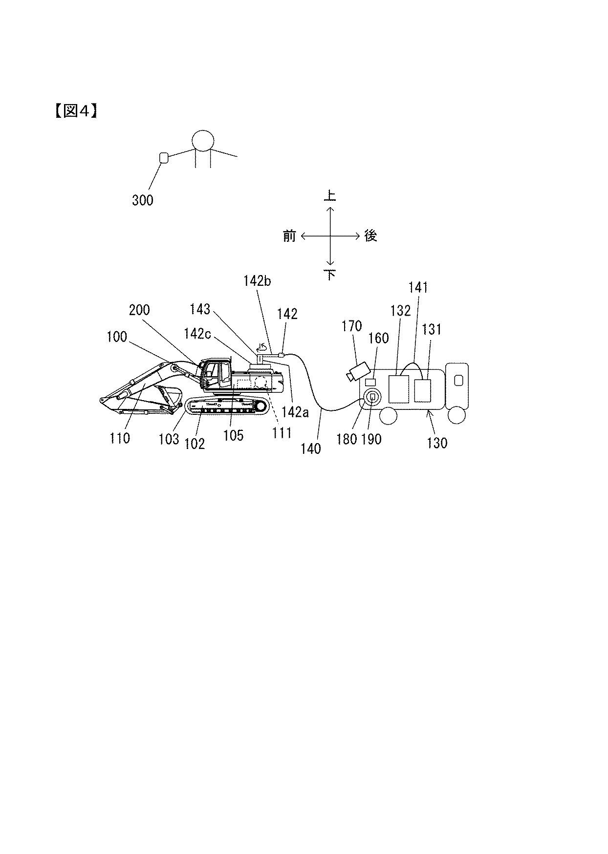
Figure 2017014687
The unit distance calculation unit 165a identifies the crawler 103 from the image G1 captured by the camera 170, as shown in FIG. The unit distance calculation unit 165a sets the horizontal width (actual size) of the crawler 103 stored in advance in the storage device as the specific section L1. As shown in FIG. 6D, the unit distance calculation unit 165a uses the number of pixels px in the x direction (horizontal direction) and the number of pixels py in the y direction (vertical direction) on the image representing the specific section L1. A length Kp per pixel (unit pixel) is calculated. The length Kp per pixel is expressed by the following equation (1).

Figure 2017014687

最短距離演算部165bは、左右一対のクローラ103とケーブル140とを特定する。最短距離演算部165bは、図6(e)に示すように、右側のクローラ103の接地面と、ケーブル140との最短距離ZRを演算する。最短距離ZRは、最短距離ZRを表す画像(仮想線分)上でのx方向(横方向)の画素数pxrとy方向(縦方向)の画素数pyrを用いて、次式(2)で表される。

Figure 2017014687
The shortest distance calculation unit 165b specifies a pair of left and right crawlers 103 and a cable 140. The shortest distance calculation unit 165b calculates the shortest distance ZR between the grounding surface of the right crawler 103 and the cable 140, as shown in FIG. The shortest distance ZR is expressed by the following equation (2) using the number of pixels pxr in the x direction (horizontal direction) and the number of pixels pyr in the y direction (vertical direction) on the image (virtual line segment) representing the shortest distance ZR. expressed.

Figure 2017014687

最短距離演算部165bは、同様に、左側のクローラ103の接地面と、ケーブル140との最短距離ZLを演算する。最短距離ZLは、最短距離ZLを表す画像(仮想線分)上でのx方向(横方向)の画素数pxlとy方向(縦方向)の画素数pylを用いて、次式(3)で表される。

Figure 2017014687
Similarly, the shortest distance calculation unit 165b calculates the shortest distance ZL between the grounding surface of the left crawler 103 and the cable 140. The shortest distance ZL is expressed by the following equation (3) using the number of pixels pxl in the x direction (horizontal direction) and the number of pixels pyl in the y direction (vertical direction) on the image (virtual line segment) representing the shortest distance ZL. expressed.

Figure 2017014687

最短距離演算部165bは、最短距離ZRおよび最短距離ZLのうち、短い方を最短距離Xとして設定し、コントローラ160の記憶装置に記憶する。最短距離Xの演算処理は、所定の制御周期ごとに演算される。   The shortest distance calculation unit 165b sets the shorter one of the shortest distance ZR and the shortest distance ZL as the shortest distance X, and stores it in the storage device of the controller 160. The calculation process of the shortest distance X is calculated every predetermined control cycle.

なお、クローラ103をシンボルとして特定し、クローラ103の横幅を特定区間L1として、ケーブル140とクローラ103との最短距離Xを求める例について説明したが、その他のシンボルを利用してもよい。たとえば、図6(b)に示すように、カウンタウエイト101の後面には、「TEST MARK」の文字列がシンボルマークM1として塗装により形成されている。「TEST MARK」の文字列の実形状を表す情報が、予めコントローラ160の記憶装置に記憶されており、単位距離演算部165aによってシンボルマークM1の特定が可能とされている。コントローラ160の記憶装置には、文字列の最初の文字である「T」の中心と、文字列の最後の文字である「K」の中心とを結ぶ線分の寸法(実寸)が特定区間L2として記憶されている。これにより、上述の式(1)〜(3)における特定区間L1に代えて特定区間L2を用いることで、最短距離Xを求めることができる。   In addition, although the example which calculates | requires the shortest distance X of the cable 140 and the crawler 103 by specifying the crawler 103 as a symbol and making the horizontal width of the crawler 103 into the specific area L1 was demonstrated, you may utilize another symbol. For example, as shown in FIG. 6B, a character string “TEST MARK” is formed on the rear surface of the counterweight 101 as a symbol mark M1 by painting. Information representing the actual shape of the character string “TEST MARK” is stored in advance in the storage device of the controller 160, and the symbol mark M1 can be specified by the unit distance calculation unit 165a. In the storage device of the controller 160, the dimension (actual size) of the line segment connecting the center of “T” that is the first character of the character string and the center of “K” that is the last character of the character string is the specific section L2. Is remembered as Accordingly, the shortest distance X can be obtained by using the specific section L2 instead of the specific section L1 in the above-described formulas (1) to (3).

その他の例として、図6(b)に示すように、矩形状のシンボルマークM2を一対形成しておき、一対のシンボルマークM2間の寸法を特定区間L3として用いることもできる。一対のシンボルマークM2間の寸法(実寸)は、予めコントローラ160の記憶装置に記憶されている。この場合も同様に、上述の式(1)〜(3)における特定区間L1に代えて特定区間L3を用いることで最短距離Xを求めることができる。   As another example, as shown in FIG. 6B, a pair of rectangular symbol marks M2 may be formed, and the dimension between the pair of symbol marks M2 may be used as the specific section L3. The dimension (actual dimension) between the pair of symbol marks M2 is stored in the storage device of the controller 160 in advance. In this case as well, the shortest distance X can be obtained by using the specific section L3 instead of the specific section L1 in the above formulas (1) to (3).

図7はコントローラ160によるケーブル巻取駆動処理および過荷重警報送信処理の内容を示すフローチャートであり、図14はコントローラ160における接近警報送信処理の一例を示すフローチャートである。図7および図14のフローチャートに示す処理は、それぞれ、たとえば図示しないイグニッションスイッチのオンにより開始され、図示しない初期設定が行われた後、繰り返し実行される。図14に示す処理は、図7の処理とは別ループで行われる処理であり、クローラ103とケーブル140間の最短距離Xを常時監視し、最短距離Xが警報用距離閾値Xmin未満となったときに、警報を送信する処理である。   FIG. 7 is a flowchart showing the contents of cable winding drive processing and overload warning transmission processing by the controller 160, and FIG. 14 is a flowchart showing an example of approach warning transmission processing in the controller 160. Each of the processes shown in the flowcharts of FIGS. 7 and 14 is started by turning on an ignition switch (not shown), for example, and is repeatedly executed after an initial setting (not shown) is performed. The process shown in FIG. 14 is a process performed in a loop different from the process of FIG. 7, and the shortest distance X between the crawler 103 and the cable 140 is constantly monitored, and the shortest distance X is less than the alarm distance threshold value Xmin. Sometimes it is a process to send an alarm.

(ケーブル巻取駆動処理および過荷重警報送信処理)
図7に示すように、ステップS101において、コントローラ160は、張力検出装置190で検出された情報である張力F1を取得し、ステップS106へ進む。ステップS106において、コントローラ160は、ステップS101で取得した張力F1が、第1閾値Fa未満であるか否かを判定する。ステップS106で否定判定されると、ステップS111へ進み、ステップS106で肯定判定されると、ステップS136へ進む。
(Cable winding drive processing and overload alarm transmission processing)
As shown in FIG. 7, in step S101, the controller 160 acquires the tension F1 that is information detected by the tension detector 190, and proceeds to step S106. In step S106, the controller 160 determines whether or not the tension F1 acquired in step S101 is less than the first threshold value Fa. If a negative determination is made in step S106, the process proceeds to step S111, and if a positive determination is made in step S106, the process proceeds to step S136.

ステップS111において、コントローラ160は、ステップS101で取得した張力F1が、警報用張力閾値Fmax未満か否かを判定する。ステップS111で肯定判定されるとステップS101へ戻り、ステップS111で否定判定されるとステップS126へ進む。   In step S111, the controller 160 determines whether or not the tension F1 acquired in step S101 is less than the alarm tension threshold Fmax. If an affirmative determination is made in step S111, the process returns to step S101, and if a negative determination is made in step S111, the process proceeds to step S126.

ステップS126において、コントローラ160は、過荷重情報(警報信号)を情報端末200および情報端末300に送信して、図7に示す処理を終了する。   In step S126, the controller 160 transmits overload information (alarm signal) to the information terminal 200 and the information terminal 300, and ends the process shown in FIG.

ステップS106で肯定判定され、ステップS136に進むと、ステップS136において、コントローラ160は、カメラ170により撮影された画像G1からクローラ103とケーブル140との間の最短距離Xを演算して、ステップS141へ進む。   When an affirmative determination is made in step S106 and the process proceeds to step S136, in step S136, the controller 160 calculates the shortest distance X between the crawler 103 and the cable 140 from the image G1 captured by the camera 170, and the process proceeds to step S141. move on.

ステップS141において、コントローラ160は、最短距離Xが距離閾値La未満であるか否かを判定する。ステップS141で肯定判定されるとステップS146へ進み、ステップS141で否定判定されるとステップS101へ戻る。   In step S141, the controller 160 determines whether or not the shortest distance X is less than the distance threshold La. If an affirmative determination is made in step S141, the process proceeds to step S146, and if a negative determination is made in step S141, the process returns to step S101.

ステップS146において、コントローラ160は、ステップS136で演算された最短距離Xを距離閾値Xcとして設定し、記憶装置に記憶させ、ステップS151へ進む。   In step S146, the controller 160 sets the shortest distance X calculated in step S136 as the distance threshold value Xc, stores it in the storage device, and proceeds to step S151.

ステップS151において、コントローラ160は、ケーブル巻取装置180のモータ(不図示)に回転信号(巻き取り信号)を出力してケーブル巻取装置180によりケーブル140の巻き取り動作(回収方向に回転動作)を実行させ、ステップS161へ進む。   In step S151, the controller 160 outputs a rotation signal (winding signal) to a motor (not shown) of the cable winding device 180, and the cable winding device 180 winds the cable 140 (rotation operation in the collecting direction). And the process proceeds to step S161.

ステップS161において、コントローラ160は、カメラ170により撮影された画像G1からクローラ103とケーブル140との間の最短距離Xを演算して、ステップS166へ進む。   In step S161, the controller 160 calculates the shortest distance X between the crawler 103 and the cable 140 from the image G1 photographed by the camera 170, and proceeds to step S166.

ステップS166において、コントローラ160は、最短距離Xが距離閾値Xc未満であるか否かを判定する。ステップS166で肯定判定されるとステップS171へ進み、ステップS166で否定判定されるとステップS153へ進む。   In step S166, the controller 160 determines whether or not the shortest distance X is less than the distance threshold value Xc. If an affirmative determination is made in step S166, the process proceeds to step S171. If a negative determination is made in step S166, the process proceeds to step S153.

ステップS171において、コントローラ160は、ケーブル巻取装置180のモータ(不図示)へ停止信号を出力し、ケーブル140の巻き取り動作を停止させ、ステップ101へ戻る。   In step S171, the controller 160 outputs a stop signal to a motor (not shown) of the cable winding device 180, stops the winding operation of the cable 140, and returns to step 101.

ステップS153において、コントローラ160は、張力検出装置190で検出された情報である張力F1を取得し、ステップS156へ進む。ステップS156において、コントローラ160は、ステップS153で取得した張力F1が、第2閾値Fb以上であるか否かを判定する。ステップS156で否定判定されると、ステップS146へ戻り、ステップS156で肯定判定されると、ステップS158へ進む。   In step S153, the controller 160 acquires the tension F1, which is information detected by the tension detector 190, and proceeds to step S156. In step S156, the controller 160 determines whether or not the tension F1 acquired in step S153 is greater than or equal to the second threshold value Fb. If a negative determination is made in step S156, the process returns to step S146, and if a positive determination is made in step S156, the process proceeds to step S158.

ステップS158において、コントローラ160は、ケーブル巻取装置180のモータ(不図示)へ停止信号を出力し、ケーブル140の巻き取り動作を停止させ、ステップ101へ戻る。   In step S158, the controller 160 outputs a stop signal to the motor (not shown) of the cable winding device 180, stops the winding operation of the cable 140, and returns to step 101.

(接近警報送信処理)
図14に示す接近警報送信処理は、所定の制御周期で繰り返し実行される。つまり、本実施の形態では、図14に示すように、最短距離Xと警報用距離閾値Xminとの比較を、常時行っている。ステップS180において、コントローラ160は、カメラ170により撮影された画像G1からクローラ103とケーブル140との間の最短距離Xを演算して、ステップS181へ進む。
(Access warning transmission processing)
The approach warning transmission process shown in FIG. 14 is repeatedly executed at a predetermined control cycle. That is, in this embodiment, as shown in FIG. 14, the comparison between the shortest distance X and the alarm distance threshold value Xmin is always performed. In step S180, the controller 160 calculates the shortest distance X between the crawler 103 and the cable 140 from the image G1 photographed by the camera 170, and proceeds to step S181.

ステップS181において、コントローラ160は、ステップS180で演算された最短距離Xが、警報用距離閾値Xmin未満か否かを判定する。ステップS181で肯定判定されるとステップS186へ進み、ステップS181で否定判定されるとステップS180へ戻る。   In step S181, the controller 160 determines whether or not the shortest distance X calculated in step S180 is less than the alarm distance threshold value Xmin. If a positive determination is made in step S181, the process proceeds to step S186, and if a negative determination is made in step S181, the process returns to step S180.

ステップS186において、コントローラ160は、接近情報(警報信号)を情報端末200および情報端末300に送信して、図14に示す処理を終了する。   In step S186, the controller 160 transmits approach information (alarm signal) to the information terminal 200 and the information terminal 300, and ends the process shown in FIG.

本実施の形態の動作をまとめると次のようになる。図8は、油圧ショベル100と電源車130との相対位置の変化の一例を示す平面模式図である。運転者が、イグニッションスイッチをオンすると、車両が起動する。図8(a)に示すように、ケーブル140が繰り出されることなく、地面上で撓んでいる状態では、ケーブル140の張力F1が第1閾値Fa未満となっている。このとき、コントローラ160は、所定の制御周期でクローラ103とケーブル140との最短距離Xを演算し、距離閾値Laと比較することで、最短距離Xが距離閾値La未満になることがないか常時監視している状態にある(S106でYes→S136→S141でNo)。   The operation of the present embodiment is summarized as follows. FIG. 8 is a schematic plan view illustrating an example of a change in relative position between the excavator 100 and the power supply vehicle 130. When the driver turns on the ignition switch, the vehicle is activated. As shown in FIG. 8A, the tension F1 of the cable 140 is less than the first threshold Fa when the cable 140 is bent out on the ground without being drawn out. At this time, the controller 160 calculates the shortest distance X between the crawler 103 and the cable 140 at a predetermined control cycle and compares it with the distance threshold La to determine whether the shortest distance X is less than the distance threshold La. Monitoring is in progress (Yes in S106 → S136 → No in S141).

図8(a)に示す状態から、油圧ショベル100が移動したり、旋回したりする際に、ケーブル140の張力F1が第1閾値Fa以上になると、ケーブル140がケーブル巻取装置180のドラムから繰り出される(ケーブル巻放出方向回転)。このとき、コントローラ160は、ケーブル140に過大な荷重が作用することがないか常時監視している状態にある(S106でNo,S111でYes)。   When the excavator 100 moves or turns from the state shown in FIG. 8A and the tension F1 of the cable 140 becomes equal to or greater than the first threshold value Fa, the cable 140 is removed from the drum of the cable winding device 180. It is fed out (rotation in the cable winding direction). At this time, the controller 160 is constantly monitoring whether an excessive load is applied to the cable 140 (No in S106, Yes in S111).

油圧ショベル100の移動速度や旋回速度が速く、ケーブル140に警報用張力閾値Fmax以上の張力F1が作用すると、運転室104内の情報端末200や現場作業員、現場監督者が利用している情報端末300を構成するスピーカ(不図示)および表示装置(不図示)によって、ケーブル140に過荷重が発生していることが報知される(S111でNo,S126)。   When the excavator 100 has a fast moving speed and a turning speed and a tension F1 greater than the alarm tension threshold Fmax is applied to the cable 140, information used by the information terminal 200 in the cab 104, field workers, and field supervisors. A speaker (not shown) and a display device (not shown) constituting the terminal 300 notify that the cable 140 is overloaded (No in S111, S126).

図8(b)や図8(c)に示すように、油圧ショベル100が移動や旋回動作を完了し、ケーブル140に作用する張力F1が第1閾値Fa未満になると、ケーブル140の繰り出し動作が停止し、再び、最短距離Xが距離閾値La未満になることがないか常時監視している状態になる(S106でYes→S136→S141でNo)。   As shown in FIG. 8B and FIG. 8C, when the excavator 100 completes the movement or turning operation and the tension F1 acting on the cable 140 becomes less than the first threshold value Fa, the feeding operation of the cable 140 is performed. It stops, and it will be in the state which always monitors whether the shortest distance X will become less than the distance threshold value La again (Yes in S106-> S136-> No in S141).

油圧ショベル100が移動したり、旋回したりする際に、ケーブル140とクローラ103との最短距離Xが距離閾値La未満になると、ケーブル巻取装置180によるケーブル140の巻き取り動作が実行される(S141でYes)。   When the excavator 100 moves or turns, if the shortest distance X between the cable 140 and the crawler 103 is less than the distance threshold La, the cable winding device 180 performs the winding operation of the cable 140 ( Yes in S141).

ケーブル140の巻き取り動作中、コントローラ160は、所定の制御周期でクローラ103とケーブル140との最短距離Xを演算し、距離閾値Xcと比較することで、最短距離Xが距離閾値Xc未満になることがないか常時監視している状態にある(S151→S161→S166でNo)。距離閾値Xcは、常時更新される(S161→S166でNo→S156でNo→S146で距離閾値XcがS161で演算された最短距離Xに設定される)。ケーブル140とクローラ103との最短距離Xが、減少することが判定されると、ケーブル140の巻き取り動作が停止する(S166でYes)。   During the winding operation of the cable 140, the controller 160 calculates the shortest distance X between the crawler 103 and the cable 140 at a predetermined control cycle and compares it with the distance threshold value Xc, so that the shortest distance X becomes less than the distance threshold value Xc. It is in a state of constantly monitoring whether or not there is any (No in S151 → S161 → S166). The distance threshold Xc is constantly updated (No in S161 → S166, No → S156, No → S146, and the distance threshold Xc is set to the shortest distance X calculated in S161). When it is determined that the shortest distance X between the cable 140 and the crawler 103 is decreased, the winding operation of the cable 140 is stopped (Yes in S166).

ケーブル140の巻き取り動作中、コントローラ160は、所定の制御周期で張力F1を取得し、第2閾値Fbと比較する(S153→S156)。ケーブル140の巻き取り動作は、地面上に置かれ、撓んだケーブル140が直線状となって、ケーブル140に作用する張力F1が第2閾値Fb以上になると、終了する(S156でYes)。   During the winding operation of the cable 140, the controller 160 acquires the tension F1 at a predetermined control cycle and compares it with the second threshold value Fb (S153 → S156). The winding operation of the cable 140 is ended when the cable 140 placed on the ground is bent and the tension F1 acting on the cable 140 becomes equal to or greater than the second threshold Fb (Yes in S156).

本実施の形態において、コントローラ160は、最短距離Xが警報用距離閾値Xminよりも短くなることがないか常時監視している状態にある(図14のS180→S181でNo)。   In the present embodiment, the controller 160 is constantly monitoring whether the shortest distance X is shorter than the alarm distance threshold value Xmin (No in S180 → S181 in FIG. 14).

ケーブル140とクローラ103とが接近するような動作(移動や旋回)が行われ、最短距離Xが警報用距離閾値Xminよりも短くなると、運転室104内の情報端末200や現場作業員、現場監督者が利用している情報端末300を構成するスピーカ(不図示)および表示装置(不図示)によって、警報が出力される(S181でYes)。たとえば、ケーブル140とクローラ103とが接近しており、運転者による操作の継続に起因して、クローラ103によってケーブル140が踏まれてしまうおそれがあることを音声や表示画像によって、運転者や現場作業員、現場監督者に知らせる。   When the movement (turning or turning) is performed so that the cable 140 and the crawler 103 approach each other and the shortest distance X becomes shorter than the alarm distance threshold value Xmin, the information terminal 200 in the cab 104, the field worker, the field supervisor An alarm is output by a speaker (not shown) and a display device (not shown) that constitute the information terminal 300 used by the person (Yes in S181). For example, the fact that the cable 140 and the crawler 103 are close to each other and the cable 140 may be stepped on by the crawler 103 due to the continuation of the operation by the driver is indicated by a voice or a display image based on the voice or the display image. Inform workers and field supervisors.

上述した実施の形態によれば、次の作用効果が得られる。
(1)油圧ショベル100は、走行体102、旋回体105、フロント作業装置110のそれぞれを駆動する電動モータ111を支持する共用支持台125を有する旋回フレーム105fを備えている。共用支持台125は、電動モータ111に代えてエンジン191を支持可能な構成とされている。1台の油圧ショベル100で、電動モータ111およびエンジン191のそれぞれを支持することができるので、工事現場の地域において、安価に入手できるエネルギー源に対応した駆動源を選択し、作業コストの低減を図ることができる。
According to the embodiment described above, the following operational effects can be obtained.
(1) The hydraulic excavator 100 includes a turning frame 105f having a common support base 125 that supports an electric motor 111 that drives each of the traveling body 102, the turning body 105, and the front work device 110. The shared support stand 125 is configured to support the engine 191 instead of the electric motor 111. Since one hydraulic excavator 100 can support each of the electric motor 111 and the engine 191, a drive source corresponding to an energy source that can be obtained at low cost is selected in the construction site area, thereby reducing the work cost. Can be planned.

(2)電動モータ111を共用支持台125によって支持させる場合、モータ用ブラケット121を介して、電動モータ111が支持される。エンジン191を共用支持台125によって支持させる場合、エンジン用ブラケット129を介して、エンジン191が支持される。エンジン191および電動モータ111のいずれか一方を共用支持台125に支持させる際、支持対象となる駆動源用の支持ブラケットを準備するだけでよいので、部品共通化に伴うコストの増加を抑えることができる。 (2) When the electric motor 111 is supported by the shared support base 125, the electric motor 111 is supported via the motor bracket 121. When the engine 191 is supported by the shared support base 125, the engine 191 is supported via the engine bracket 129. When supporting either one of the engine 191 and the electric motor 111 on the shared support base 125, it is only necessary to prepare a support bracket for the drive source to be supported, thereby suppressing an increase in cost due to common parts. it can.

(3)コントローラ160は、カメラ170により撮影された画像に基づいて、油圧ショベル100のクローラ103とケーブル140との最短距離Xが警報用距離閾値Xminよりも小さいか否かを判定する。最短距離Xが警報用距離閾値Xminよりも小さいと判定された場合、コントローラ160は、接近情報(警報)を情報端末200および情報端末300に送信する。これにより、ケーブル140がクローラ103に接近しており、ケーブル140がクローラ103に踏まれてしまう可能性が高い状態にあることを、情報端末200や情報端末300により、運転者や現場作業員、現場監督者等に知らせることができる。ケーブル140がクローラ103によって踏まれてしまう前に、運転者は作業を中止し、電源車130やケーブル140の移動などの適切な対応をとることができるので、ケーブル140がクローラ103によって踏まれてしまうことを防止できる。また、接近情報(警報)が発せられていない場合は、ケーブル140がクローラ103によって踏まれてしまうおそれが無いので、電源車130を頻繁に移動させる必要がない。つまり、本実施の形態によれば、電源車130の移動を最小限に抑えることができるので、作業の効率の向上を図ることもできる。さらに、ケーブル140がクローラ103に接近した場合に、運転者や現場作業員、現場監督者等に知らせることができるので、運転者の負担を軽減することができる。その結果、運転者は作業に専念することができるので、作業効率の向上を図ることができる。 (3) The controller 160 determines whether or not the shortest distance X between the crawler 103 of the excavator 100 and the cable 140 is smaller than the alarm distance threshold value Xmin based on the image taken by the camera 170. When it is determined that the shortest distance X is smaller than the alarm distance threshold value Xmin, the controller 160 transmits approach information (alarm) to the information terminal 200 and the information terminal 300. As a result, the information terminal 200 and the information terminal 300 indicate that the cable 140 is close to the crawler 103 and that the cable 140 is likely to be stepped on by the crawler 103. You can inform on-site supervisors. Before the cable 140 is stepped on by the crawler 103, the driver can stop the work and take appropriate measures such as the movement of the power supply car 130 and the cable 140, so that the cable 140 is stepped on by the crawler 103. Can be prevented. Further, when the approach information (alarm) is not issued, there is no possibility that the cable 140 is stepped on by the crawler 103, and therefore it is not necessary to move the power supply vehicle 130 frequently. That is, according to the present embodiment, the movement of the power supply vehicle 130 can be minimized, so that the work efficiency can be improved. Furthermore, when the cable 140 approaches the crawler 103, it is possible to notify the driver, the site worker, the site supervisor, etc., so that the burden on the driver can be reduced. As a result, since the driver can concentrate on the work, the work efficiency can be improved.

(4)油圧ショベル100は、距離演算用のシンボルを備えている。なお、シンボルには、たとえば、クローラ103やシンボルマークM1,M2を採用することができる。コントローラ160は、カメラ170により撮影された画像G1内のシンボルの画像に基づいて画像G1を構成する1画素あたりの距離を決定する。コントローラ160は、1画素あたりの距離およびカメラ170により撮影された上記画像G1内の油圧ショベル100のクローラ103の画像およびケーブル140の画像に基づいて、油圧ショベル100のクローラ103とケーブル140との距離を決定する。これにより、リアルタイムでクローラ103とケーブル140との距離を決定することができる。 (4) The excavator 100 includes a symbol for distance calculation. For example, the crawler 103 or the symbol marks M1 and M2 can be used as the symbol. The controller 160 determines the distance per pixel constituting the image G1 based on the symbol image in the image G1 photographed by the camera 170. The controller 160 determines the distance between the crawler 103 of the excavator 100 and the cable 140 based on the distance per pixel and the image of the crawler 103 of the excavator 100 and the image of the cable 140 in the image G1 taken by the camera 170. To decide. Thereby, the distance between the crawler 103 and the cable 140 can be determined in real time.

−第2の実施の形態−
図9を参照して、第2の実施の形態に係る電動作業補助システムを説明する。なお、図中、第1の実施の形態と同一もしくは相当部分には、同一の参照番号を付し、相違点を主に説明する。図9は、第2の実施の形態に係る電動作業補助システムを構成する油圧ショベル100、電源車130およびケーブル240を示す平面模式図である。
-Second Embodiment-
With reference to FIG. 9, the electric work assistance system which concerns on 2nd Embodiment is demonstrated. In the figure, the same or corresponding parts as those in the first embodiment are denoted by the same reference numerals, and differences will mainly be described. FIG. 9 is a schematic plan view showing the hydraulic excavator 100, the power supply car 130, and the cable 240 that constitute the electric work assist system according to the second embodiment.

第2の実施の形態の電動作業補助システムは、第1の実施の形態の電動作業補助システムと同様の構成を有している。第2の実施の形態の電動作業補助システムが第1の実施の形態と異なる点は、ケーブル240に複数のマーク244が付されている点である。ケーブル240には、ケーブル240の長手方向に沿って、等間隔にマーク244が設けられている。マーク244は、たとえば、蛍光色や金属光沢を有する特殊な色を有する塗料により形成される。   The electric work assistance system of the second embodiment has the same configuration as the electric work assistance system of the first embodiment. The electric work assistance system of the second embodiment is different from the first embodiment in that a plurality of marks 244 are attached to the cable 240. The cable 240 is provided with marks 244 at equal intervals along the longitudinal direction of the cable 240. The mark 244 is formed of a paint having a special color having a fluorescent color or a metallic luster, for example.

第2の実施の形態では、単位距離演算部165a(図5(b)参照)が、カメラ170により撮影された画像G1から隣接するマーク244間の寸法を特定区間L4として設定する。コントローラ160の記憶装置には、隣接するマーク244間の寸法(実寸)が記憶されている。第2の実施の形態でも同様に、上述の式(1)〜(3)における特定区間L1に代えて特定区間L4を用いることで最短距離Xを求めることができる。   In the second embodiment, the unit distance calculation unit 165a (see FIG. 5B) sets the dimension between the adjacent marks 244 from the image G1 captured by the camera 170 as the specific section L4. The storage device of the controller 160 stores the size (actual size) between adjacent marks 244. Similarly, in the second embodiment, the shortest distance X can be obtained by using the specific section L4 instead of the specific section L1 in the above formulas (1) to (3).

このような第2の実施の形態によれば、第1の実施の形態と同様の作用効果に加え、次の作用効果を奏する。
(5)蛍光色や金属光沢を有する特殊な色でマーク244を構成することで、建設現場などに存在する種々の物体の中からケーブル240を認識することが容易になる。また、夜間など、建設現場が暗い環境であった場合でもケーブル240を認識することが容易になる。
According to such 2nd Embodiment, in addition to the effect similar to 1st Embodiment, there exists the following effect.
(5) By configuring the mark 244 with a special color having a fluorescent color or metallic luster, it is easy to recognize the cable 240 from various objects existing at a construction site or the like. In addition, the cable 240 can be easily recognized even when the construction site is in a dark environment such as at night.

−第3の実施の形態−
図10(a)を参照して、第3の実施の形態に係る電動作業補助システムを説明する。なお、図中、第1の実施の形態と同一もしくは相当部分には、同一の参照番号を付し、相違点を主に説明する。図10(a)は、第3の実施の形態に係るコントローラにおける警報送信処理の一例を示すフローチャートである。第3の実施の形態では、第1の実施の形態で説明した処理(図7参照)に加え、図10(a)に示す処理が実行される。
-Third embodiment-
With reference to Fig.10 (a), the electrically-driven work assistance system which concerns on 3rd Embodiment is demonstrated. In the figure, the same or corresponding parts as those in the first embodiment are denoted by the same reference numerals, and differences will mainly be described. FIG. 10A is a flowchart illustrating an example of alarm transmission processing in the controller according to the third embodiment. In the third embodiment, the process shown in FIG. 10A is executed in addition to the process described in the first embodiment (see FIG. 7).

図10(a)に示すように、ステップS302において、コントローラ160は、撮影された画像G1からケーブル140の長さLcを演算する。ケーブル140の長さLcの演算方法は、上述したケーブル140とクローラ103との最短距離Xの演算方法と同様である。すなわち、コントローラ160は、クローラ103などのシンボルの実寸と撮影されたシンボルの画像から、1画素あたりの長さKpを演算する。コントローラ160は、撮影されたケーブル140を構成する画像の画素数にKpを乗じることでケーブル140の長さLcを求める。   As shown in FIG. 10A, in step S302, the controller 160 calculates the length Lc of the cable 140 from the captured image G1. The calculation method of the length Lc of the cable 140 is the same as the calculation method of the shortest distance X between the cable 140 and the crawler 103 described above. That is, the controller 160 calculates the length Kp per pixel from the actual size of the symbol such as the crawler 103 and the photographed symbol image. The controller 160 obtains the length Lc of the cable 140 by multiplying the number of pixels of the image constituting the photographed cable 140 by Kp.

ステップS302において、ケーブル長さLcが演算されると、ステップS308に進む。ステップS308において、コントローラ160は、ケーブル長さLcが長さ閾値Lc1以上であるか否かを判定する。ステップS308で肯定判定されるとステップS314へ進み、ステップS308で否定判定されるとステップS302に戻る。   When the cable length Lc is calculated in step S302, the process proceeds to step S308. In step S308, the controller 160 determines whether or not the cable length Lc is greater than or equal to the length threshold Lc1. If an affirmative determination is made in step S308, the process proceeds to step S314. If a negative determination is made in step S308, the process returns to step S302.

ステップS314において、コントローラ160は、警報信号を情報端末200および情報端末300に送信して、図10(a)に示す処理を終了する。   In step S314, the controller 160 transmits an alarm signal to the information terminal 200 and the information terminal 300, and ends the process illustrated in FIG.

このような第3の実施の形態によれば、第1の実施の形態と同様の作用効果に加え、次の作用効果を奏する。
(6)コントローラ160は、カメラ170により撮影された画像G1に基づいて、ケーブル140の長さLcを決定し、ケーブル140の長さLcが所定長Lc1よりも長い場合に、所定情報を情報端末200,300に送信する。このような構成とすることにより、ケーブル140が必要以上に引き出されることを防止できる。さらに、ケーブル140が最大長さまで引き出されたときに、ケーブル140に過度な張力が作用することを防止できるので、ケーブル140やケーブルスタンド142等が損傷することを防止できる。
According to such 3rd Embodiment, in addition to the effect similar to 1st Embodiment, there exists the following effect.
(6) The controller 160 determines the length Lc of the cable 140 based on the image G1 photographed by the camera 170. When the length Lc of the cable 140 is longer than the predetermined length Lc1, the controller 160 sends the predetermined information to the information terminal. 200, 300. With such a configuration, the cable 140 can be prevented from being pulled out more than necessary. Furthermore, since it is possible to prevent excessive tension from acting on the cable 140 when the cable 140 is pulled out to the maximum length, the cable 140, the cable stand 142, and the like can be prevented from being damaged.

−第4の実施の形態−
図10(b)を参照して、第4の実施の形態に係る電動作業補助システムを説明する。なお、図中、第1の実施の形態と同一もしくは相当部分には、同一の参照番号を付し、相違点を主に説明する。図10(b)は、第4の実施の形態に係るコントローラにおける警報送信処理の一例を示すフローチャートである。第4の実施の形態では、第1の実施の形態で説明した処理(図7参照)に加え、図10(b)に示す処理が実行される。
-Fourth embodiment-
With reference to FIG.10 (b), the electrically-driven work assistance system which concerns on 4th Embodiment is demonstrated. In the figure, the same or corresponding parts as those in the first embodiment are denoted by the same reference numerals, and differences will mainly be described. FIG. 10B is a flowchart illustrating an example of alarm transmission processing in the controller according to the fourth embodiment. In the fourth embodiment, the process shown in FIG. 10B is executed in addition to the process described in the first embodiment (see FIG. 7).

図10(b)に示すように、ステップ402において、コントローラ160は、撮影された画像G1から油圧ショベル100と電源車130との最短距離dを演算する。最短距離dの演算方法は、上述したケーブル140とクローラ103との最短距離Xの演算方法と同様である。すなわち、コントローラ160は、クローラ103などのシンボルの実寸と撮影されたシンボルの画像から、1画素あたりの長さKpを演算する。コントローラ160は、撮影された油圧ショベル100と電源車130とを直線で結び、結んだ線分を構成する画像の画素数にKpを乗じることで最短距離dを求める。   As shown in FIG. 10B, in step 402, the controller 160 calculates the shortest distance d between the excavator 100 and the power supply vehicle 130 from the captured image G1. The calculation method of the shortest distance d is the same as the calculation method of the shortest distance X between the cable 140 and the crawler 103 described above. That is, the controller 160 calculates the length Kp per pixel from the actual size of the symbol such as the crawler 103 and the photographed symbol image. The controller 160 connects the photographed excavator 100 and the power supply vehicle 130 with a straight line, and obtains the shortest distance d by multiplying the number of pixels of the image constituting the connected line segment by Kp.

ステップS402において、最短距離dが演算されると、ステップS408に進む。ステップS408において、コントローラ160は、最短距離dが長さ閾値d1未満であるか否かを判定する。ステップS408で肯定判定されるとステップS414へ進み、ステップS408で否定判定されるとステップS402に戻る。   When the shortest distance d is calculated in step S402, the process proceeds to step S408. In step S408, the controller 160 determines whether or not the shortest distance d is less than the length threshold value d1. If a positive determination is made in step S408, the process proceeds to step S414, and if a negative determination is made in step S408, the process returns to step S402.

ステップS414において、コントローラ160は、警報信号を情報端末200および情報端末300に送信して、図10(b)に示す処理を終了する。   In step S414, the controller 160 transmits an alarm signal to the information terminal 200 and the information terminal 300, and ends the process illustrated in FIG.

このような第4の実施の形態によれば、第1の実施の形態と同様の作用効果に加え、次の作用効果を奏する。
(7)コントローラ160は、油圧ショベル100と電源車130との最短距離dを決定し、油圧ショベル100と電源車130との最短距離dが所定距離d1よりも短い場合に、所定情報を情報端末200,300に送信する。このような構成とすることで、油圧ショベル100と電源車130との接触を回避することができる。
According to such 4th Embodiment, in addition to the effect similar to 1st Embodiment, there exists the following effect.
(7) The controller 160 determines the shortest distance d between the excavator 100 and the power supply vehicle 130, and when the shortest distance d between the excavator 100 and the power supply vehicle 130 is shorter than the predetermined distance d1, the controller 160 transmits the predetermined information to the information terminal. 200, 300. With such a configuration, contact between the excavator 100 and the power supply vehicle 130 can be avoided.

−第5の実施の形態−
図11および図12を参照して、第5の実施の形態に係る電動作業補助システムを説明する。なお、図中、第1の実施の形態と同一もしくは相当部分には、同一の参照番号を付し、相違点を主に説明する。図11は、第5の実施の形態に係るコントローラにおけるケーブル巻取駆動処理の一例を示すフローチャートである。第5の実施の形態では、第1の実施の形態で説明した処理(図7参照)に加え、図11に示す処理が実行される。
-Fifth embodiment-
With reference to FIG. 11 and FIG. 12, the electric work assistance system which concerns on 5th Embodiment is demonstrated. In the figure, the same or corresponding parts as those in the first embodiment are denoted by the same reference numerals, and differences will mainly be described. FIG. 11 is a flowchart illustrating an example of cable winding drive processing in the controller according to the fifth embodiment. In the fifth embodiment, the process shown in FIG. 11 is executed in addition to the process described in the first embodiment (see FIG. 7).

図11に示すように、ステップS521において、コントローラ160は、撮影された画像G1から地面上に置かれたケーブル140を識別して、ステップS525へ進む。ステップS525において、コントローラ160は、ケーブル140を構成する画像が予め記憶装置に記憶されている形状であるか否かを判定する。本実施の形態では、コントローラ160の記憶装置に予めU字およびO字の形状が記憶されている。コントローラ160は、記憶装置に記憶された形状(U字およびO字)と、撮影されたケーブル140の画像の形状とを比較する。   As shown in FIG. 11, in step S521, the controller 160 identifies the cable 140 placed on the ground from the photographed image G1, and proceeds to step S525. In step S525, the controller 160 determines whether or not the image forming the cable 140 has a shape stored in advance in the storage device. In the present embodiment, U-shaped and O-shaped shapes are stored in advance in the storage device of the controller 160. The controller 160 compares the shape (U shape and O shape) stored in the storage device with the shape of the image of the photographed cable 140.

図12は、ケーブル140の配置状態の一例を示す模式図である。図12(a)に示すようにケーブル140がU字状に配置されている場合や、図12(b)に示すようにケーブル140がO字状に配置されている場合、ステップS525で肯定判定されて、ステップS527へ進む。   FIG. 12 is a schematic diagram illustrating an example of an arrangement state of the cable 140. If the cable 140 is arranged in a U-shape as shown in FIG. 12A, or if the cable 140 is arranged in an O-shape as shown in FIG. 12B, an affirmative determination is made in step S525. Then, the process proceeds to step S527.

ステップS527において、コントローラ160は、ケーブル巻取装置180のモータ(不図示)に回転信号(巻き取り信号)を出力してケーブル巻取装置180によりケーブル140の巻き取り動作を実行させ、ステップS521へ戻る。   In step S527, the controller 160 outputs a rotation signal (winding signal) to a motor (not shown) of the cable winding device 180 to cause the cable winding device 180 to perform the winding operation of the cable 140, and then proceeds to step S521. Return.

ケーブル140が巻き取られることで、ケーブル140の配置形状がU字状やO字状でなくなると、ステップS525において、否定判定されてステップS529へ進む。ステップS529において、コントローラ160は、ケーブル巻取装置180のモータ(不図示)へ停止信号を出力し、ケーブル140の巻き取り動作を停止させ、ステップ521へ戻る。   When the cable 140 is wound up and the arrangement shape of the cable 140 is not U-shaped or O-shaped, a negative determination is made in step S525, and the process proceeds to step S529. In step S529, the controller 160 outputs a stop signal to a motor (not shown) of the cable winding device 180, stops the winding operation of the cable 140, and returns to step 521.

このような第5の実施の形態によれば、第1の実施の形態と同様の作用効果に加え、次の作用効果を奏する。
(8)コントローラ160は、カメラ170により撮影された画像に基づいて、ケーブル140の形状を特定することで、ケーブル140の長さを推定する。コントローラ160は、ケーブル140の長さLcが所定長Lc1よりも長いことを表す形状(たとえば、U字状やO字状)を検出したとき、ケーブル巻取装置180によりケーブル140の巻取動作を実行する。このような構成とすることにより、ケーブル140が必要以上に引き出されることを防止できる。さらに、ケーブル140が最大長さまで引き出されたときに、ケーブル140に過度な張力が作用することを防止できるので、ケーブル140やケーブルスタンド142等が損傷することを防止できる。
According to such 5th Embodiment, in addition to the effect similar to 1st Embodiment, there exists the following effect.
(8) The controller 160 estimates the length of the cable 140 by specifying the shape of the cable 140 based on the image captured by the camera 170. When the controller 160 detects a shape (for example, a U shape or an O shape) representing that the length Lc of the cable 140 is longer than the predetermined length Lc1, the controller 160 performs the winding operation of the cable 140 by the cable winding device 180. Run. With such a configuration, the cable 140 can be prevented from being pulled out more than necessary. Furthermore, since it is possible to prevent excessive tension from acting on the cable 140 when the cable 140 is pulled out to the maximum length, the cable 140, the cable stand 142, and the like can be prevented from being damaged.

次のような変形も本発明の範囲内であり、変形例の一つ、もしくは複数を上述の実施形態と組み合わせることも可能である。
(変形例1)
上述した実施の形態では、クローラ103とケーブル140との最短距離Xを演算するために、カメラ170により撮影された画像G1を用いる例について説明したが、本発明はこれに限定されない。たとえば、レーザを用いた距離測定装置により、クローラ103とケーブル140との最短距離Xを決定してもよい。この場合、油圧ショベル100の走行体102と、走行体102近傍のケーブル140の位置を確認できるように、走行体102近傍の範囲にレーザを走査して、クローラ103とケーブル140との距離を測定する。
The following modifications are also within the scope of the present invention, and one or a plurality of modifications can be combined with the above-described embodiment.
(Modification 1)
In the above-described embodiment, the example in which the image G1 captured by the camera 170 is used to calculate the shortest distance X between the crawler 103 and the cable 140 has been described, but the present invention is not limited to this. For example, the shortest distance X between the crawler 103 and the cable 140 may be determined by a distance measuring device using a laser. In this case, the distance between the crawler 103 and the cable 140 is measured by scanning the laser in a range near the traveling body 102 so that the traveling body 102 of the excavator 100 and the position of the cable 140 near the traveling body 102 can be confirmed. To do.

(変形例2)
上述した実施の形態では、電源車130に取り付けられたカメラ170により撮影された画像G1に基づいて、クローラ103とケーブル140との最短距離Xを演算する例について説明したが、本発明はこれに限定されない。図13に示すように、油圧ショベル100の旋回体105にカメラ370を設け、このカメラ370で撮影された画像に基づいて、クローラ103とケーブル140との最短距離Xを演算してもよい。第1の実施の形態に比べて、クローラ103とケーブル140により近い位置で、クローラ103とケーブル140との相関関係を監視できるので、より精度の高い最短距離Xの演算ができる。なお、電源車130および油圧ショベル100のそれぞれにカメラを設けて、両者によって撮影された画像に基づいて演算された最短距離の平均値を所定の閾値(LaやXc)と比較するようにしてもよい。
(Modification 2)
In the above-described embodiment, the example in which the shortest distance X between the crawler 103 and the cable 140 is calculated based on the image G1 photographed by the camera 170 attached to the power supply car 130 has been described. It is not limited. As shown in FIG. 13, a camera 370 may be provided on the swing body 105 of the excavator 100, and the shortest distance X between the crawler 103 and the cable 140 may be calculated based on an image captured by the camera 370. Compared with the first embodiment, since the correlation between the crawler 103 and the cable 140 can be monitored at a position closer to the crawler 103 and the cable 140, the calculation of the shortest distance X can be performed with higher accuracy. It should be noted that a camera is provided in each of the power supply vehicle 130 and the hydraulic excavator 100, and the average value of the shortest distance calculated based on the images photographed by both is compared with a predetermined threshold (La or Xc). Good.

(変形例3)
第3の実施の形態では、カメラ170により撮影された画像G1に基づいて、ケーブル140の長さLcを演算し、ケーブル140の長さLcが所定長Lc1よりも長いことが判定されたときに警報を送信する例について説明したが、本発明はこれに限定されない。たとえば、ケーブル140にマークを付し、カメラ170で撮影された画像G1の中にマークが検出された場合に、ケーブル140の長さLcが所定長Lc1よりも長いと判定し、警報を送信してもよい。また、カメラ170を使用せず、ドラムの回転数をポテンショメータ等で検出し、検出された回転数に基づいて、ケーブル140の長さLcが所定長Lc1よりも長いと判定し、警報を送信してもよい。
(Modification 3)
In the third embodiment, when the length Lc of the cable 140 is calculated based on the image G1 photographed by the camera 170 and it is determined that the length Lc of the cable 140 is longer than the predetermined length Lc1. Although an example of transmitting an alarm has been described, the present invention is not limited to this. For example, when the mark is attached to the cable 140 and the mark is detected in the image G1 photographed by the camera 170, it is determined that the length Lc of the cable 140 is longer than the predetermined length Lc1, and an alarm is transmitted. May be. Further, the number of rotations of the drum is detected by a potentiometer or the like without using the camera 170, and based on the detected number of rotations, it is determined that the length Lc of the cable 140 is longer than the predetermined length Lc1, and an alarm is transmitted. May be.

(変形例4)
第3の実施の形態では、ケーブル140の長さLcが所定長Lc1よりも長いことが判定されたときに警報を送信する例について説明したが、警報の送信に代えて、もしくは警報の送信とともに、ケーブル巻取装置180にケーブル140の巻き取り動作を実行させてもよい。つまり、変形例3に示すような方法でケーブル140の長さLcが所定長Lc1よりも長いと判定された場合において、ケーブル巻取装置180によりケーブル140の巻取り動作を実行させてもよい。
(Modification 4)
In the third embodiment, the example in which the alarm is transmitted when it is determined that the length Lc of the cable 140 is longer than the predetermined length Lc1 has been described, but instead of the alarm transmission or with the alarm transmission. The cable winding device 180 may execute the winding operation of the cable 140. That is, when it is determined that the length Lc of the cable 140 is longer than the predetermined length Lc1 by a method as shown in Modification 3, the cable winding device 180 may perform the winding operation of the cable 140.

(変形例5)
上述した実施の形態では、インバータ132とバッテリ131とを一の車両(電源車130)に搭載する例について説明したが、本発明はこれに限定されない。図15に示すように、インバータ132を搭載するインバータ車両630Aと、バッテリ131を搭載するバッテリ車両630Bとを分けてもよい。この場合、インバータ車両630Aとバッテリ車両630Bは、着脱自在に連結部639に接続されている。また、インバータ132とバッテリ131とは、着脱自在のケーブル141により接続されている。
(Modification 5)
In the above-described embodiment, the example in which the inverter 132 and the battery 131 are mounted on one vehicle (power supply car 130) has been described, but the present invention is not limited to this. As shown in FIG. 15, the inverter vehicle 630A on which the inverter 132 is mounted and the battery vehicle 630B on which the battery 131 is mounted may be separated. In this case, inverter vehicle 630A and battery vehicle 630B are detachably connected to connecting portion 639. The inverter 132 and the battery 131 are connected by a detachable cable 141.

コントローラ160は、バッテリ131の充電量を監視しており、バッテリ車両630Bに搭載されたバッテリ131の充電量が低下した場合に、情報端末200,300に充電量低下を表す情報を送信する。これにより、充電量が低下したバッテリ131を搭載したバッテリ車両630Bを、充電済みのバッテリを搭載した他のバッテリ車両と交換することができるので、連続した作業が可能となる。   The controller 160 monitors the charge amount of the battery 131, and transmits information indicating the charge amount decrease to the information terminals 200 and 300 when the charge amount of the battery 131 mounted on the battery vehicle 630B decreases. As a result, the battery vehicle 630B on which the battery 131 having a reduced charge amount is mounted can be replaced with another battery vehicle on which a charged battery is mounted, so that continuous work can be performed.

(変形例6)
上述した実施の形態では、コントローラ160が電源車130に搭載される例について説明したが本発明はこれに限定されない。コントローラ160の機能を油圧ショベル100の制御装置に持たせてもよい。この場合、電源車130に搭載されたカメラ170からの情報を油圧ショベル100の制御装置に送信すればよい。制御装置は、警報信号を情報端末300に送信し、巻き取り信号をケーブル巻取装置180に送信する。
(Modification 6)
In the above-described embodiment, the example in which the controller 160 is mounted on the power supply vehicle 130 has been described, but the present invention is not limited to this. The control device of the excavator 100 may have the function of the controller 160. In this case, information from the camera 170 mounted on the power supply vehicle 130 may be transmitted to the control device of the excavator 100. The control device transmits an alarm signal to the information terminal 300 and transmits a winding signal to the cable winding device 180.

(変形例7)
上述した実施の形態では、ケーブル巻取装置180は、巻き取りのみをモータの駆動により行う例について説明したが、本発明はこれに限定されない。繰り出しもモータの駆動により行ってもよい。
(Modification 7)
In the above-described embodiment, the cable winding device 180 has been described with respect to an example in which only winding is performed by driving a motor. However, the present invention is not limited to this. The feeding may be performed by driving the motor.

(変形例8)
カメラ170は、電源車130に1台備える場合に限定されず、複数備えてもよい。同様に、カメラ370は、油圧ショベル100に1台備える場合に限定されず、複数備えてもよい。
(Modification 8)
The camera 170 is not limited to the case where one power supply car 130 is provided, and a plurality of cameras 170 may be provided. Similarly, the camera 370 is not limited to the case where one camera is provided in the excavator 100, and a plurality of cameras 370 may be provided.

(変形例9)
上述した実施の形態では、油圧ショベル100に本発明を適用した例について説明したが、本発明はこれに限定されることなく、ホイールショベル、クレーンなどの種々の建設機械に適用することができる。
(Modification 9)
In the above-described embodiment, the example in which the present invention is applied to the hydraulic excavator 100 has been described. However, the present invention is not limited to this, and can be applied to various construction machines such as a wheel excavator and a crane.

上記では、種々の実施の形態および変形例を説明したが、本発明はこれらの内容に限定されるものではない。本発明の技術的思想の範囲内で考えられるその他の態様も本発明の範囲内に含まれる。   Although various embodiments and modifications have been described above, the present invention is not limited to these contents. Other embodiments conceivable within the scope of the technical idea of the present invention are also included in the scope of the present invention.

100 油圧ショベル(建設機械)、102 走行体、103 クローラ(距離演算用のシンボル)、105 旋回体、105f 旋回フレーム(フレーム)、110 フロント作業装置(作業装置)、111 電動モータ、121 モータ用ブラケット(電動モータ用の支持ブラケット)、125 共用支持台(支持部)、129 エンジン用ブラケット(エンジン用の支持ブラケット)、130 電源車、131 バッテリ(電源装置)、132 インバータ(電源装置)、140 ケーブル、160 コントローラ(制御装置)、170 カメラ(撮影装置)、180 ケーブル巻取装置、191 エンジン、200 情報端末、240 ケーブル、244 マーク(距離演算用のシンボル)、300 情報端末、370 カメラ(撮影装置) DESCRIPTION OF SYMBOLS 100 Hydraulic excavator (construction machine), 102 traveling body, 103 crawler (symbol for distance calculation), 105 revolving body, 105f revolving frame (frame), 110 front working device (working device), 111 electric motor, 121 bracket for motor (Support bracket for electric motor), 125 shared support base (support part), 129 bracket for engine (support bracket for engine), 130 power supply car, 131 battery (power supply device), 132 inverter (power supply device), 140 cable , 160 controller (control device), 170 camera (imaging device), 180 cable winding device, 191 engine, 200 information terminal, 240 cable, 244 mark (symbol for distance calculation), 300 information terminal, 370 camera (imaging device) )

Claims (6)

走行体、前記走行体上に設けられた旋回体、前記旋回体に設けられた作業装置、ならびに、前記走行体、前記旋回体、および前記作業装置のそれぞれを駆動するための圧油を供給する油圧ポンプ、ならびに、前記油圧ポンプを駆動する電動モータを備えた建設機械と、
前記建設機械に搭載された前記電動モータにケーブルを介して電力を供給する電源装置を備えた電源車と、
前記建設機械および前記電源車の少なくとも一方に設けられた撮影装置と、
前記撮影装置により撮影された画像に基づいて、前記建設機械と前記ケーブルとの距離が所定距離よりも小さいか否かを判定する制御装置とを備え、
前記制御装置は、前記建設機械と前記ケーブルとの距離が前記所定距離よりも小さいと判定された場合に、所定情報を情報端末に送信する、電動作業補助システム。
A traveling body, a revolving body provided on the traveling body, a working device provided on the revolving body, and pressure oil for driving each of the traveling body, the revolving body, and the working device are supplied. A hydraulic pump, and a construction machine including an electric motor that drives the hydraulic pump;
A power supply vehicle including a power supply device that supplies electric power to the electric motor mounted on the construction machine via a cable;
A photographing device provided in at least one of the construction machine and the power supply vehicle;
A control device for determining whether a distance between the construction machine and the cable is smaller than a predetermined distance based on an image photographed by the photographing device;
The electric control system, wherein the control device transmits predetermined information to an information terminal when it is determined that a distance between the construction machine and the cable is smaller than the predetermined distance.
請求項1に記載の電動作業補助システムにおいて、
前記建設機械および前記ケーブルのいずれかに、距離演算用のシンボルが設けられ、
前記制御装置は、前記撮影装置により撮影された前記シンボルの画像に基づいて前記撮影装置により撮影された画像を構成する1画素あたりの距離を決定し、前記1画素あたりの距離および前記撮影装置により撮影された前記建設機械および前記ケーブルの画像に基づいて、前記建設機械と前記ケーブルとの距離を決定する、電動作業補助システム。
In the electric work assistance system according to claim 1,
Either of the construction machine and the cable is provided with a symbol for distance calculation,
The control device determines a distance per pixel constituting an image photographed by the photographing device based on an image of the symbol photographed by the photographing device, and determines the distance per pixel and the photographing device. The electric work assistance system which determines the distance of the said construction machine and the said cable based on the image | photographed said construction machine and the said cable.
請求項1に記載の電動作業補助システムにおいて、
前記制御装置は、前記撮影装置により撮影された画像に基づいて、前記ケーブルの長さを決定し、前記ケーブルの長さが所定長よりも長い場合に、所定情報を情報端末に送信する、電動作業補助システム。
In the electric work assistance system according to claim 1,
The control device determines the length of the cable based on an image photographed by the photographing device, and transmits predetermined information to the information terminal when the length of the cable is longer than a predetermined length. Work assistance system.
請求項1に記載の電動作業補助システムにおいて、
前記制御装置は、前記建設機械と前記電源車との距離を決定し、前記建設機械と前記電源車との距離が所定距離よりも短い場合に、所定情報を情報端末に送信する、電動作業補助システム。
In the electric work assistance system according to claim 1,
The control device determines a distance between the construction machine and the power supply vehicle, and transmits predetermined information to the information terminal when the distance between the construction machine and the power supply vehicle is shorter than a predetermined distance. system.
請求項1に記載の電動作業補助システムにおいて、
前記電源車は、前記ケーブルを巻き取り可能なケーブル巻取装置を備え、
前記制御装置は、前記撮影装置により撮影された画像に基づいて、前記ケーブルの長さを決定し、前記ケーブルの長さが所定長よりも長い場合に前記ケーブル巻取装置に前記ケーブルの巻取動作を実行させる、電動作業補助システム。
In the electric work assistance system according to claim 1,
The power supply vehicle includes a cable winding device capable of winding the cable,
The control device determines a length of the cable based on an image photographed by the photographing device, and winds the cable to the cable winding device when the length of the cable is longer than a predetermined length. An electric work assistance system that performs operations.
請求項1に記載の電動作業補助システムにおいて、
前記建設機械は、前記電動モータを支持する支持部を有するフレームを備え、
前記支持部は、前記電動モータに代えてエンジンを支持可能な構成とされ、
前記電動モータを前記支持部によって支持させる場合、電動モータ用の支持ブラケットを介して、前記電動モータが支持され、
前記エンジンを前記支持部によって支持させる場合、エンジン用の支持ブラケットを介して、前記エンジンが支持される、電動作業補助システム。
In the electric work assistance system according to claim 1,
The construction machine includes a frame having a support portion that supports the electric motor,
The support portion is configured to be able to support an engine instead of the electric motor,
When the electric motor is supported by the support portion, the electric motor is supported via a support bracket for the electric motor,
When the engine is supported by the support portion, the electric work assistance system in which the engine is supported via a support bracket for the engine.
JP2015128844A 2015-06-26 2015-06-26 Electric work auxiliary system Pending JP2017014687A (en)

Priority Applications (1)

Application Number Priority Date Filing Date Title
JP2015128844A JP2017014687A (en) 2015-06-26 2015-06-26 Electric work auxiliary system

Applications Claiming Priority (1)

Application Number Priority Date Filing Date Title
JP2015128844A JP2017014687A (en) 2015-06-26 2015-06-26 Electric work auxiliary system

Publications (1)

Publication Number Publication Date
JP2017014687A true JP2017014687A (en) 2017-01-19

Family

ID=57830112

Family Applications (1)

Application Number Title Priority Date Filing Date
JP2015128844A Pending JP2017014687A (en) 2015-06-26 2015-06-26 Electric work auxiliary system

Country Status (1)

Country Link
JP (1) JP2017014687A (en)

Cited By (7)

* Cited by examiner, † Cited by third party
Publication number Priority date Publication date Assignee Title
JP2021191139A (en) * 2020-06-01 2021-12-13 株式会社アイチコーポレーション Mobile power storage power supply system
EP4012109A1 (en) * 2020-12-09 2022-06-15 BAUER Maschinen GmbH Construction machine
CN115066349A (en) * 2020-02-12 2022-09-16 卡特彼勒Sarl Disconnect assembly for a tethered electric vehicle
JP2022172819A (en) * 2021-05-07 2022-11-17 株式会社日立建機ティエラ Construction machine
WO2023074793A1 (en) * 2021-10-29 2023-05-04 株式会社日立建機ティエラ Electric construction machine
WO2024070368A1 (en) * 2022-09-30 2024-04-04 株式会社日立建機ティエラ Power feed system for electric construction machinery
EP4317610A4 (en) * 2021-03-22 2025-05-07 Hitachi Construction Machinery Tierra Co., Ltd. Electric work machine

Cited By (17)

* Cited by examiner, † Cited by third party
Publication number Priority date Publication date Assignee Title
CN115066349A (en) * 2020-02-12 2022-09-16 卡特彼勒Sarl Disconnect assembly for a tethered electric vehicle
US12558974B2 (en) 2020-02-12 2026-02-24 Caterpillar Sarl Disconnection assembly for tethered electric vehicle
CN115066349B (en) * 2020-02-12 2025-09-30 卡特彼勒Sarl Disconnect assembly for tethered electric vehicles
JP2021191139A (en) * 2020-06-01 2021-12-13 株式会社アイチコーポレーション Mobile power storage power supply system
EP4012109A1 (en) * 2020-12-09 2022-06-15 BAUER Maschinen GmbH Construction machine
WO2022122406A1 (en) * 2020-12-09 2022-06-16 Bauer Maschinen Gmbh Construction machine
US12508919B2 (en) 2020-12-09 2025-12-30 Bauer Maschinen Gmbh Construction machine
EP4317610A4 (en) * 2021-03-22 2025-05-07 Hitachi Construction Machinery Tierra Co., Ltd. Electric work machine
JP2022172819A (en) * 2021-05-07 2022-11-17 株式会社日立建機ティエラ Construction machine
JP2025109926A (en) * 2021-05-07 2025-07-25 株式会社日立建機ティエラ Construction Machinery
CN117881856A (en) * 2021-10-29 2024-04-12 株式会社日立建机Tierra Electric construction machinery
JP7588249B2 (en) 2021-10-29 2024-11-21 株式会社日立建機ティエラ Electric Construction Machinery
US20240392540A1 (en) * 2021-10-29 2024-11-28 Hitachi Construction Machinery Tierra Co., Ltd. Electric construction machine
JPWO2023074793A1 (en) * 2021-10-29 2023-05-04
WO2023074793A1 (en) * 2021-10-29 2023-05-04 株式会社日立建機ティエラ Electric construction machine
JPWO2024070368A1 (en) * 2022-09-30 2024-04-04
WO2024070368A1 (en) * 2022-09-30 2024-04-04 株式会社日立建機ティエラ Power feed system for electric construction machinery

Similar Documents

Publication Publication Date Title
CN106797449B (en) Peripheral monitoring device for crawler-type work machines
CN107079089B (en) Periphery monitoring device for working machine
JP6589468B2 (en) Perimeter display device for mobile crane
EP2708663A1 (en) Device for displaying rearward field of view of hydraulic shovel
JP6888287B2 (en) crane
WO2019208283A1 (en) Crane vehicle
JP2010185274A (en) Construction machinery with monitoring camera
JP2012172350A (en) Work machine periphery monitoring method and system utilizing fisheye lens
JP7616511B2 (en) Remote operation support system, remote operation support device
CN113727937A (en) Crane, crane body, and mobile body
JP2018017011A (en) System for moving electrically-driven work machine
JP2019049117A (en) Construction machine
WO2020050201A1 (en) Work vehicle
JPH0948584A (en) Camera equipment for mobile cranes and traveling monitoring equipment
JP5937534B2 (en) Electric construction machine
JP7588249B2 (en) Electric Construction Machinery
JP7532696B2 (en) Obstacle detection system around heavy machinery
JP3226637U (en) Remote work support system
KR102019780B1 (en) Working machine
JP2017061283A (en) Work vehicle ambient monitoring device
KR20260047246A (en) Power control system and power control method
JP2022156791A (en) Shovel and information processing device
JP6686561B2 (en) Crane operation support device
WO2024204510A1 (en) Work machine
JP2025070512A (en) Work support system and work machine

Legal Events

Date Code Title Description
RD04 Notification of resignation of power of attorney

Free format text: JAPANESE INTERMEDIATE CODE: A7424

Effective date: 20161012

A521 Written amendment

Free format text: JAPANESE INTERMEDIATE CODE: A523

Effective date: 20161130