JP2017015111A - Crush prevention tool for end of channel steel - Google Patents
Crush prevention tool for end of channel steel Download PDFInfo
- Publication number
- JP2017015111A JP2017015111A JP2015129556A JP2015129556A JP2017015111A JP 2017015111 A JP2017015111 A JP 2017015111A JP 2015129556 A JP2015129556 A JP 2015129556A JP 2015129556 A JP2015129556 A JP 2015129556A JP 2017015111 A JP2017015111 A JP 2017015111A
- Authority
- JP
- Japan
- Prior art keywords
- steel
- portions
- channel steel
- lip
- flat plate
- Prior art date
- Legal status (The legal status is an assumption and is not a legal conclusion. Google has not performed a legal analysis and makes no representation as to the accuracy of the status listed.)
- Granted
Links
Images


Landscapes
- Assembled Shelves (AREA)
- Connection Of Plates (AREA)
- Furniture Connections (AREA)
- Bolts, Nuts, And Washers (AREA)
- Mutual Connection Of Rods And Tubes (AREA)
Abstract
【課題】リップ付き溝形鋼の端部をボルトによって他の部材に取り付けるときに、前記ボルトの締め過ぎによって、前記リップ付き溝形鋼が変形するのを防止する手段として活用することが出来る潰れ防止具を提供する。【解決手段】Uターン部20によって内端どうしが接続された一対の平板状部分21a,21b、この平板状部分の外端に形成されたストッパー部19、及び両平板状部分に外向きに突出するように形成された抜け止め用係止突起22を備え、当該係止突起22は、溝形鋼のリップ部16間の間隔よりも巾広であって、少なくとも片側のストッパー部19が溝形鋼の背板部14の端面に隣接したとき、当該背板部に形成された横長の係止孔23に片側の抜け止め用係止突起22が嵌合するように構成され、この溝形鋼の端部と他部材とを連結するボルト24が、Uターン部20の内側で、この溝形鋼の左右両側板部15間を貫通する構成。【選択図】図7Crushing can be utilized as a means for preventing deformation of a lip-shaped channel steel due to excessive tightening of the bolt when the end of the lip-shaped channel steel is attached to another member with a bolt. Providing prevention tools. SOLUTION: A pair of flat plate portions 21a and 21b whose inner ends are connected to each other by a U-turn portion 20, a stopper portion 19 formed at an outer end of the flat plate portion, and outwardly projecting from both flat plate portions. The locking projection 22 is formed so as to have a width wider than the interval between the lip portions 16 of the grooved steel, and at least the stopper portion 19 on one side is a groove shape. When it adjoins the end surface of the steel backplate part 14, it is comprised so that the latching protrusion 22 for one side prevention may be fitted in the horizontally long locking hole 23 formed in the said backplate part, and this channel steel The bolt 24 which connects an edge part of this and other members penetrates between the right-and-left both-sides board part 15 of this channel steel inside the U-turn part 20. FIG. [Selection] Figure 7
Description
本発明は、枠組み構造のラックなどにおいて、ボルトにより取り付けられるリップ付き溝形鋼の端部、に使用される潰れ防止具に関するものである。 The present invention relates to a crush prevention device used for an end portion of a grooved steel with a lip attached by a bolt in a rack or the like having a frame structure.
例えば、枠組み構造のラックの棚用構造体を支持するラチス構造の側枠構造体には、前後一対の支柱間に架設されるラチス材としてリップ付き溝形鋼が活用されている。この溝形鋼の端部は、横断面形状がコの字形の支柱の左右両側板間に挟まれた状態で、これらを水平に貫通するボルトによって締結されるものであるが、前記ボルトの締め過ぎにより、支柱の左右両側板と共に、溝形鋼の左右両側板部が互いに接近する内側に変形する恐れがある。従って、特許文献1にも示されるように、溝形鋼の端部内に嵌合させるタイプの潰れ防止具を組み込むことが考えられている。この特許文献1に記載された潰れ防止具は、溝形鋼端部のボルト貫通箇所におけるリップ部を切欠除去し、このリップ部切除跡を利用して、当該溝形鋼の左右両側板部間を貫通するボルトを包むように、角U字形の潰れ防止具を溝形鋼内に、当該溝形鋼の長さ方向に対して直角向きに差込み、当該角U字形の潰れ防止具の両側板遊端の突出片を、溝形鋼の背板部に設けられた2つの横長スリットに差し込み、当該突出片の先端部に形成した抜け止め用凸部を前記横長スリットの外側に突出させることにより、角U字形の潰れ防止具の不測の脱落を防止する構成になっている。
For example, in a lattice structure side frame structure that supports a rack structure rack structure frame structure, a grooved steel with a lip is used as a lattice material laid between a pair of front and rear columns. The ends of the channel steel are fastened by bolts that horizontally penetrate the left and right side plates of a U-shaped support having a transverse cross-sectional shape. As a result, both the left and right side plates of the column and the right and left side plates of the channel steel may be deformed inwardly approaching each other. Therefore, as disclosed in
上記特許文献1に記載された溝形鋼端部の潰れ防止具では、リップ付き溝形鋼の端部のリップ部を切除しなければならないばかりでなく、溝形鋼の背板部に2つの横長スリットを設けなければならないことにより、溝形鋼の端部の強度が著しく低下することが考えられる。しかも、ボルトナットにより溝形鋼の端部を支柱の左右両側板間に取り付けた状態においても、前記抜け止め用凸部と前記横長スリットとの係合強度が低い場合、ボルトの締め付けが緩んだときに、角U字形の潰れ防止具が溝形鋼から不測に脱落する恐れも考えられる。
In the device for preventing crushing of a grooved steel end described in
本発明は、上記のような従来の問題点を解消することのできる溝形鋼連結部の潰れ防止具を提案するものであって、本発明に係る溝形鋼連結部の潰れ防止具は、後述する実施例との関係を理解し易くするために、当該実施例の説明において使用した参照符号を括弧付きで付して示すと、リップ付き溝形鋼の端部から当該溝形鋼の長さ方向に差し込まれる潰れ防止具であって、両側辺が溝形鋼の左右両側板部(15)内面に隣接する巾の一対の平板状部分(21a,21b)、この両平板状部分(21a,21b)の内端をつなぐUターン部(20)、両平板状部分(21a,21b)の外端から外側に折曲連設されたストッパー部(19)、及び両平板状部分(21a,21b)に外向きに突出するように形成された抜け止め用係止突起(22)を備え、当該係止突起(22)は、溝形鋼のリップ部(16)間の間隔よりも巾広であって、前記ストッパー部(19)の内の少なくとも片側のストッパー部(19)が溝形鋼の背板部(14)の端面に隣接したとき、当該背板部(14)に形成された横長の係止孔(23)に片側の抜け止め用係止突起(22)が嵌合するように構成され、この溝形鋼の端部と他部材とを連結するボルト(24)が、前記Uターン部(20)の内側で、この溝形鋼の左右両側板部(15)間を貫通する構成になっている。
The present invention proposes a collapsible preventing tool for the grooved steel connecting part capable of solving the conventional problems as described above, and the collapsible preventing tool for the grooved steel connecting part according to the present invention includes: In order to facilitate understanding of the relationship with the examples described later, when the reference numerals used in the description of the examples are shown in parentheses, the length of the channel steel from the end of the channel steel with lips is shown. A pair of flat plate-shaped portions (21a, 21b) having widths adjacent to the inner surfaces of the left and right side plate portions (15) of the grooved steel, both flat plate portions (
上記構成の潰れ防止具は、前記支柱など、他の部材にボルトで取り付ける前に、一対の平板状部分が溝形鋼の背板部とリップ部の内側に隣接するように、Uターン部側から溝形鋼内に、当該溝形鋼の長さ方向に差し込むことにより、その差込み深さを、少なくとも溝形鋼の背板部側のストッパー部と当該背板部の端面との当接により制限させると共に、この潰れ防止具が溝形鋼内から抜け出すのを、前記背板部に設けられた横長の係止孔と、当該背板部に隣接する側の平板状部分の抜け止め用係止突起との嵌合により、防止させることが出来る。このように潰れ防止具が溝形鋼の端部内に組み込まれたならば、この溝形鋼の左右両側板部を貫通するボルトにより、当該溝形鋼の端部を他の部材、例えば前記支柱の左右両側板間に取り付けることが出来る。 The collapsing prevention device having the above-described configuration is arranged on the U-turn portion side so that the pair of flat plate portions are adjacent to the inside of the back plate portion and the lip portion of the grooved steel before being attached to other members such as the support columns with bolts. Is inserted into the grooved steel in the longitudinal direction of the grooved steel so that the insertion depth is at least due to the contact between the stopper on the grooved steel back plate side and the end surface of the backplate part. In addition to restricting the crushing prevention tool from slipping out of the channel steel, a horizontally long locking hole provided in the back plate portion and a locking member for preventing the flat plate portion adjacent to the back plate portion from coming off. This can be prevented by fitting with the stop protrusion. If the crush prevention device is incorporated in the end portion of the channel steel in this way, the end of the channel steel is connected to another member, for example, the column by the bolts penetrating the left and right side plate portions of the channel steel. It can be attached between the left and right side plates.
上記のように溝形鋼端部に組み込まれた潰れ防止具は、前記ボルトが貫通する左右両側板部間が、当該ボルトの締め過ぎにより、互いに接近する内側へ変形する状況にあっても、その変形を、この潰れ防止具のUターン部と一対の平板状部分とで阻止させることが出来るのであるが、特に上記の本発明の構成によれば、リップ付き溝形鋼に対する加工は、背板部に1つの横長係止孔を加工するだけであるから、特許文献1に記載されたような従来構成と比較して、リップ付き溝形鋼の端部の強度をそれほど低下させずに済む。しかも、この溝形鋼の左右両側板部間をボルトが貫通した後は、前記抜け止め用係止突起と溝形鋼背板部の係止孔との係合力が弱くとも、この潰れ防止具が溝形鋼端部内から不測に抜け落ちることは皆無であり、この潰れ防止具のUターン部と一対の平板状部分とによる潰れ防止効果を、常に確実に維持出来るものである。
Even if the crush prevention tool incorporated in the end of the grooved steel as described above is in a situation where the left and right side plate portions through which the bolt penetrates are deformed inward to each other due to overtightening of the bolt, The deformation can be prevented by the U-turn portion and the pair of flat plate portions of the anti-collapse tool. Since only one oblong locking hole is machined in the plate portion, the strength of the end portion of the lip-shaped channel steel can be reduced as compared with the conventional configuration as described in
勿論、U字形の両端部を、溝形鋼の背板部端部とリップ部端部とに嵌合するように外側に折り返し、この両端の折り返し部と、溝形鋼の背板部端部及びリップ部端部との摩擦力で、この潰れ防止具を位置決めする構成も考えられるが、上記本発明の構成によれば、溝形鋼端部の背板部とリップ部の外側に被さる部分が無く、しかも、前記潰れ防止具が溝形鋼の端部に組み込まれた状態において、その両平板状部分の先端のストッパー部が、溝形鋼の背板部の外側面及びリップ部の外側面から突出しないように構成することにより、この溝形鋼の端部の背板部やリップ部の外側に他の部材が当接するような状況でも問題なく使用出来る。又、溝形鋼端部への潰れ防止具の組み込みに際しても、少なくとも片側のストッパー部が溝形鋼背板部の端面に隣接する深さまで、潰れ防止具を溝形鋼内に差し込むだけで、一対の平板状部分の弾性復帰により、片側の抜け止め用係止突起を溝形鋼側の横長の係止孔に嵌合させて、確実な位置決め効果が得られるのであるから、潰れ防止具の差し込みの最終段階で特に強く押し込む必要も無いし、両平板状部分を弾性に抗して内側に寄せるなどの余分な手間も不要である。 Of course, the U-shaped end portions are folded outward so as to be fitted to the back plate end portion and the lip end portion of the grooved steel, and the folded portions at both ends and the back plate end of the channel steel. In addition, a configuration in which the collapsing prevention tool is positioned by the frictional force with the end portion of the lip portion is also conceivable, but according to the configuration of the present invention, the portion covering the back plate portion of the grooved steel end portion and the outside of the lip portion In addition, in the state where the crush prevention device is incorporated in the end portion of the grooved steel, the stopper portions at the tips of both flat plate portions are outside the outer surface of the back plate portion and the lip portion of the grooved steel. By being configured so as not to protrude from the side surface, it can be used without problems even in a situation where other members abut against the back plate portion or the lip portion of the end portion of the channel steel. Also, when incorporating the crush prevention tool into the end of the grooved steel, just insert the crush prevention tool into the grooved steel until at least the stopper on one side is adjacent to the end surface of the grooved steel back plate, With the elastic return of the pair of flat plate-like parts, the locking protrusion for retaining on one side is fitted into the horizontally long locking hole on the grooved steel side, and a reliable positioning effect is obtained. There is no need to push in particularly strongly at the final stage of insertion, and there is no need for extra work such as bringing both plate-shaped parts inward against elasticity.
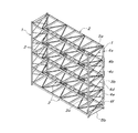
以下、本発明の潰れ防止具を組み込む枠組み構造のラックについて説明すると、図1に示されるラックは、ラック間口方向に所要間隔を隔てて配置された2つの側枠構造体1間に、棚用水平構造体2が上下方向適当間隔おきに複数段架設されたものである。棚用水平構造体2は種々の構造のものが知られており、特に限定されるものではないので、ここでは説明は省略する。側枠構造体1は、ラックの奥行き方向前後一対の支柱3a,3bと、この前後一対の支柱3a,3b間に架設された上下複数のクロスラチス4a〜4f、最上端クロスラチス4aの上端で前後一対の支柱3a,3b間に架設された上端水平連結体5a、及び最下端クロスラチス4fの下端で前後一対の支柱3a,3b間に架設された下端水平連結体5bから構成されている。側枠構造体1も、図示の構成に限定されるものではなく、ラックの規模などに応じて、使用するクロスラチスの数は、最少1つから任意の数だけ使用される。又、奥行きが大きなラックの場合、上記構成の側枠構造体1を、支柱3a,3bが互いに背中合わせに隣接するように、ラックの奥行き方向前後に配置し、必要に応じて、互いに背中合わせに隣接する支柱3a,3bを結合一体化して構成することも可能である。更に、場合によっては、上下両端の水平連結体5a,5bの内、一方を省くことも可能である。
Hereinafter, a rack having a frame structure incorporating the crush prevention device of the present invention will be described. The rack shown in FIG. 1 is used for a shelf between two
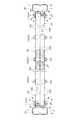
以下、図示の側枠構造体1の詳細構造を、図2〜図7に基づいて説明すると、前後一対の支柱3a,3bは、正面板6と左右両側板7とから成る横断面溝形構造のもので、左右両側板7は、その正面板6に隣接する前半部の内側間隔よりも後半部の内側間隔が狭くなって、当該後半部が、部材取付け板部8となっている。又、左右両側板7の後側辺には、外側に折曲された補強用折曲板部9が形成されている。この前後一対の支柱3a,3bは、正面板6が側枠構造体1の前後両端面を形成する向きで、前後対称に配置されている。
Hereinafter, the detailed structure of the illustrated
クロスラチス4a〜4fは、2本のラチス材10a,10bが、その長さ方向の中央位置で互いに重なってX字形に交差すると共に、その交差部が、締結具としてのボルトナット11により互いに結合されることによって構成された、全て同一構造、同一サイズのものであり、上下両水平連結体5a,5bは、2本の水平棒状体12a,12bを、その内端から一定長さ領域を左右横方向に互いに重ね合わせ、その重なり部分の中央と両端近傍の3箇所を、連結具としてのボルトナット13によって結合して一体化したものである。各クロスラチス4a〜4fを構成するラチス材10a,10bと、上下両水平連結体5a,5bを構成する水平棒状体12a,12bは、背板部14と左右両側板部15、及び左右一対のリップ部16を備えた、断面形状とサイズが同一のリップ付き溝形鋼を、左右一対のリップ部16が下側になる向きで使用しており、その横巾は、前記支柱3a,3bにおける左右両側板7の部材取付け板部8の内側面間の間隔の略半分となっている。
In the
図示の構成では、各クロスラチス4a〜4fを同じ向きで上下方向に配列させたとき、各クロスラチス4a〜4fのラチス材10a,10bの内、後ろ側支柱3bのある側が高くなる向きに傾斜するラチス材10aは、反対側の前側支柱3aのある側が高くなる向きに傾斜するラチス材10bに対して、全て外側に隣接することになる。従って、各クロスラチス4a〜4fを同じ向きで上下方向に配列させたとき、下側になるクロスラチス4b,4d,4fのラチス材10a,10bの上端部と、上側になるクロスラチス4a,4c,4eのラチス材10a,10bの下端部とを、左右横方向に互いに重ね合わせることが出来る。そして、この上下両ラチス材10a,10bの端部の重なり部は、支柱3a,3bにおける左右両側板7の部材取付け板部8の内側面間に丁度嵌合させることが出来る巾となっているので、この上下両ラチス材10a,10bの端部の重なり部を部材取付け板部8の内側面間に挟んだ状態で、これらを水平横向きに貫通する、締結具としてのボルトナット17によって、締結固定している。
In the illustrated configuration, when the
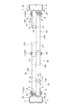
各水平連結体5a,5bの両端部(水平棒状体12a,12bの外端部)間の長さは、上記のように前後一対の支柱3a,3b間に架設したクロスラチス4a〜4fにおけるラチス材10a,10bの上端部間及び下端部間の距離と略等しく構成されている。そして水平連結体5a,5bの両端部、即ち、水平棒状体12a,12bの外端部は、その巾分だけ左右横方向に位置がずれているので、上端の水平連結体5aと下端の水平連結体5bを前後逆向きに配置することにより、上端のクロスラチス4aの外側に位置するラチス材10aの上端部内側に、上端の水平連結体5aの内側に位置する水平棒状体12bの外端部を重ね合わせると共に、上端のクロスラチス4aの内側に位置するラチス材10bの上端部外側に、上端の水平連結体5aの外側に位置する水平棒状体12aの外端部を重ね合わせることが出来る。同様に、下端のクロスラチス4fのラチス材10a,10bの下端部に、下端の水平連結体5bの水平棒状体12b,12aの外端部を水平横方向に重ね合わせることが出来る。そして、このラチス材10a,10bの端部と水平連結体5a,5bの両端部の重なり部は、支柱3a,3bにおける左右両側板7の部材取付け板部8の内側面間に丁度嵌合させることが出来る巾となっているので、当該重なり部を部材取付け板部8の内側面間に挟んだ状態で、これらを水平横向きに貫通するボルトナット17によって、締結固定している。
The length between both end portions of each
先に説明したように、クロスラチス4a〜4fを構成するラチス材10a,10bと、水平連結体5a,5bを構成する水平棒状体12a,12bは、同一構造、同一サイズの溝形鋼から構成されているので、これらラチス材10a,10bの両端部と、水平棒状体12a,12bの支柱3a,3bに連結される外端部とには、全て同一構造、同一サイズの潰れ防止具18が組み込まれている。これら潰れ防止具18は、図7に示すように、使用される溝形鋼の左右両側板部15間の横内巾に丁度収まる程度の巾の帯状鋼板(望ましくはスプリング鋼から成るもの)をU字形に曲げ加工したものであって、その両端には、外側への折曲片で構成されたストッパー部19が設けられ、Uターン部20と各ストッパー部19との間の各平板状部分21a,21bには、この鋼板の曲げ加工により外側に突出するように形成された抜け止め用係止突起22が形成されている。この一対の抜け止め用係止突起22は、平板状部分21a,21bの両側辺から内側へ切欠された狭巾部によって形成されているが、使用される溝形鋼の両リップ部16間の間隔よりも巾広である。
As described above, the
以上のように構成された潰れ防止具18は、使用されている溝形鋼の背板部14とリップ部16との間の縦内巾よりも、一対の抜け止め用係止突起22の先端間の間隔が少し大きくなる状態に成形されている。従って、溝形鋼の背板部14とリップ部16の内側に一対の平板状部分21a,21bが隣接する向きで、そしてUターン部20が先行する向きで、この潰れ防止具18を溝形鋼の端部から内部へ押し込むと、両抜け止め用係止突起22と背板部14及びリップ部16との圧接によって、両平板状部分21a,21bが互いに接近するように弾性変形した状態で、ストッパー部19が、溝形鋼の背板部14の端面とリップ部16の端面とに当接する所定深さまで、潰れ防止具18を溝形鋼の内部へ嵌合させることが出来る。このように潰れ防止具18を溝形鋼の内部へ所定深さ嵌合させたとき、溝形鋼の背板部14に隣接する平板状部分21aが備える抜け止め用係止突起22の先端が、弾性復帰力で自動的に嵌合することが出来る横長の係止孔23が当該背板部14に設けられている。而して、この係止孔23に嵌合した抜け止め用係止突起22によって、潰れ防止具18を溝形鋼内から引き出す力に対して大きな抵抗力が得られるように、各抜け止め用係止突起22は、その側面形状が、ストッパー部19のある側が、平板状部分21a,21bから垂直に立ち上がる鋸歯形状となっているが、実際には、後述するように、Uターン部20の内側をボルトが貫通するので、このボルトがセットされるまでの抜け止め効果が得られれば良く、従って、十分な弾性復帰力で片側の抜け止め用係止突起22を係止孔23に嵌合させることが出来るならば、各抜け止め用係止突起22は、側面形状が鋸歯形状ではなく、山形形状又は円弧形状であっても良い。
The
上記のように、溝形鋼の端部内に潰れ防止具18を押し込むことにより、少なくとも片側のストッパー部19と溝形鋼の背板部14の端面との当接により、潰れ防止具18の嵌合深さを制限すると共に、片側の抜け止め用係止突起22と溝形鋼側の係止孔23との嵌合により、潰れ防止具18が溝形鋼に対して抜け止めされた状態に、溝形鋼の端部内に潰れ防止具18を嵌合固定することが出来る。このとき、潰れ防止具18のUターン部20が、溝形鋼の端部の両側板部15に同心状に設けられたボルト貫通孔26より、この溝形鋼の長さ方向の中央側に位置するように、両平板状部分21a,21bの長さが設定されている。
As described above, by pressing the
クロスラチス4a〜4fを構成するラチス材10a,10bと、水平連結体5a,5bを構成する水平棒状体12a,12bの端部(それぞれを構成している溝形鋼の端部)に潰れ防止具18が嵌合固定されている状態で、これらラチス材10a,10bと水平棒状体12a,12bの端部が、先に説明したように、ボルトナット17により支柱3a,3bの左右両側板7における部材取付け板部8間に取り付けられたとき、当該ボルトナット17のボルト24は、各潰れ防止具18のUターン部20の内側において、溝形鋼の左右両側板部15のボルト貫通孔26を貫通し、当該ボルト24の端部にナット25が螺嵌される。而して、このボルトナット17による締付け作用により、支柱3a,3bの左右両側板7を介して、その内側に位置する各溝形鋼の端部の両側板部15が、互いに接近する内側へ圧縮されることになるが、各溝形鋼の端部の両側板部15間に位置する潰れ防止具18が、その平板状部分21a,21bとUターン部20とにおいてその圧縮力を受止めるので、前記ボルトナット17による締付け力が多少過大であっても、支柱3a,3bの左右両側板7とその内側の各溝形鋼の端部の両側板部15の変形を防止することが出来る。
Crush prevention tools at the ends of the
尚、各クロスラチス4a〜4fを構成するラチス材10a,10bのボルトナット11による交差部での連結箇所や、上下両端の水平連結体5a,5bを構成する水平棒状体12a,12bどうしのボルトナット13による連結箇所には、各溝形鋼に外嵌させたときに当該溝形鋼のリップ部16間に嵌合する嵌合部を備えた、溝形鋼の長さ方向の中間部に使用する潰れ防止具27を組み込むことが出来る。
It should be noted that the bolts and nuts of the
本発明に係る溝形鋼端部の潰れ防止具は、例えば枠組み構造のラックの側枠構造体を構成するリップ付き溝形鋼の端部のボルトによる連結部において、前記ボルトの締め過ぎによるリップ付き溝形鋼の変形を防止する手段として活用することが出来る。 An apparatus for preventing crushing of an end of a grooved steel according to the present invention includes, for example, a lip caused by overtightening of the bolt at a connecting part by a bolt of an end of a grooved steel with a lip constituting a side frame structure of a rack having a frame structure It can be used as a means for preventing deformation of the grooved steel.
1 側枠構造体
2 棚用水平構造体
3a,3b 支柱
4a〜4f クロスラチス
5a,5b 水平連結体
6 支柱の正面板
7 支柱の左右両側板
8 支柱の部材取付け板部
10a,10b ラチス材
11,13,17 ボルトナット
12a,12b 水平棒状体
14 溝形鋼の背板部
15 溝形鋼の左右両側板部
16 溝形鋼のリップ部
18 潰れ防止具
19 ストッパー部
20 Uターン部
21a,21b 平板状部分
22 抜け止め用係止突起
23 係止孔
24 ボルト
25 ナット
26 ボルト貫通孔
27 潰れ防止具
DESCRIPTION OF
Claims (2)
Priority Applications (1)
| Application Number | Priority Date | Filing Date | Title |
|---|---|---|---|
| JP2015129556A JP6268494B2 (en) | 2015-06-29 | 2015-06-29 | Crush prevention tool for end of channel steel |
Applications Claiming Priority (1)
| Application Number | Priority Date | Filing Date | Title |
|---|---|---|---|
| JP2015129556A JP6268494B2 (en) | 2015-06-29 | 2015-06-29 | Crush prevention tool for end of channel steel |
Publications (2)
| Publication Number | Publication Date |
|---|---|
| JP2017015111A true JP2017015111A (en) | 2017-01-19 |
| JP6268494B2 JP6268494B2 (en) | 2018-01-31 |
Family
ID=57830100
Family Applications (1)
| Application Number | Title | Priority Date | Filing Date |
|---|---|---|---|
| JP2015129556A Active JP6268494B2 (en) | 2015-06-29 | 2015-06-29 | Crush prevention tool for end of channel steel |
Country Status (1)
| Country | Link |
|---|---|
| JP (1) | JP6268494B2 (en) |
Families Citing this family (1)
| Publication number | Priority date | Publication date | Assignee | Title |
|---|---|---|---|---|
| JP7380348B2 (en) | 2020-03-10 | 2023-11-15 | 株式会社ダイフク | Pillar connection structure |
Citations (5)
| Publication number | Priority date | Publication date | Assignee | Title |
|---|---|---|---|---|
| JPH0448831U (en) * | 1990-08-30 | 1992-04-24 | ||
| JPH07330123A (en) * | 1994-06-09 | 1995-12-19 | Daifuku Co Ltd | Two member coupling structure in framed rack |
| JPH11310994A (en) * | 1998-04-30 | 1999-11-09 | Nippon Steel Corp | Reinforcement structure and reinforcement method for C-type and box-type steel building materials |
| JP2003027602A (en) * | 2001-07-13 | 2003-01-29 | Nippon Steel Corp | A method of assembling a deformation-preventing hardware and frame for joining square steel. |
| JP2007176625A (en) * | 2005-12-27 | 2007-07-12 | Toyota Industries Corp | Shelf and moving shelf |
-
2015
- 2015-06-29 JP JP2015129556A patent/JP6268494B2/en active Active
Patent Citations (5)
| Publication number | Priority date | Publication date | Assignee | Title |
|---|---|---|---|---|
| JPH0448831U (en) * | 1990-08-30 | 1992-04-24 | ||
| JPH07330123A (en) * | 1994-06-09 | 1995-12-19 | Daifuku Co Ltd | Two member coupling structure in framed rack |
| JPH11310994A (en) * | 1998-04-30 | 1999-11-09 | Nippon Steel Corp | Reinforcement structure and reinforcement method for C-type and box-type steel building materials |
| JP2003027602A (en) * | 2001-07-13 | 2003-01-29 | Nippon Steel Corp | A method of assembling a deformation-preventing hardware and frame for joining square steel. |
| JP2007176625A (en) * | 2005-12-27 | 2007-07-12 | Toyota Industries Corp | Shelf and moving shelf |
Also Published As
| Publication number | Publication date |
|---|---|
| JP6268494B2 (en) | 2018-01-31 |
Similar Documents
| Publication | Publication Date | Title |
|---|---|---|
| KR101754128B1 (en) | Furniture frame assembly | |
| KR101728636B1 (en) | Non-welding steel rail profile building structure | |
| JP6268494B2 (en) | Crush prevention tool for end of channel steel | |
| JP2021088902A (en) | Mounting structure and mounting method of ceiling louver | |
| JP5847113B2 (en) | Wood fittings | |
| JP5646096B1 (en) | Wall panel fixing bracket | |
| JP5929650B2 (en) | Earthquake-resistant partition panel | |
| JP6035068B2 (en) | Shelf guard connector and shelf guard | |
| KR101440045B1 (en) | Furniture underframe | |
| JP4154531B2 (en) | Partition and panel element mounting structure | |
| JP4967038B2 (en) | Connecting member and building structure | |
| JP6292411B2 (en) | Crush prevention tool for grooved steel joints | |
| JP2017040147A (en) | Fence fitting structure | |
| KR20160000774U (en) | Clip for packing of ceiling panel supported bar | |
| JP7110523B2 (en) | furniture with top plate | |
| KR101440041B1 (en) | Furniture underframe | |
| JPH0414656Y2 (en) | ||
| KR101440043B1 (en) | Furniture underframe | |
| KR20150058855A (en) | Timber base plate metal connectors for footing-column connecting | |
| KR200487053Y1 (en) | Ceiling Board Fixing Channel | |
| JP6545142B2 (en) | Fit in Joiner | |
| KR101749120B1 (en) | Support frame for furniture | |
| JP5511633B2 (en) | Mounting bracket for horizontal member | |
| JP6332755B2 (en) | Rack side frame structure | |
| JP2010261238A (en) | Support structure of sound insulation board of soundproof wall |
Legal Events
| Date | Code | Title | Description |
|---|---|---|---|
| A621 | Written request for application examination |
Free format text: JAPANESE INTERMEDIATE CODE: A621 Effective date: 20170210 |
|
| A977 | Report on retrieval |
Free format text: JAPANESE INTERMEDIATE CODE: A971007 Effective date: 20171121 |
|
| TRDD | Decision of grant or rejection written | ||
| A01 | Written decision to grant a patent or to grant a registration (utility model) |
Free format text: JAPANESE INTERMEDIATE CODE: A01 Effective date: 20171129 |
|
| A61 | First payment of annual fees (during grant procedure) |
Free format text: JAPANESE INTERMEDIATE CODE: A61 Effective date: 20171212 |
|
| R150 | Certificate of patent or registration of utility model |
Ref document number: 6268494 Country of ref document: JP Free format text: JAPANESE INTERMEDIATE CODE: R150 |
|
| R250 | Receipt of annual fees |
Free format text: JAPANESE INTERMEDIATE CODE: R250 |
|
| R250 | Receipt of annual fees |
Free format text: JAPANESE INTERMEDIATE CODE: R250 |
|
| R250 | Receipt of annual fees |
Free format text: JAPANESE INTERMEDIATE CODE: R250 |
|
| R250 | Receipt of annual fees |
Free format text: JAPANESE INTERMEDIATE CODE: R250 |
|
| R250 | Receipt of annual fees |
Free format text: JAPANESE INTERMEDIATE CODE: R250 |
|
| R250 | Receipt of annual fees |
Free format text: JAPANESE INTERMEDIATE CODE: R250 |